1
APPLICATION NOTE 503
Advanced remote management example with ESP2 and ESP3
inclusive 2 channel learn mode
June 1, 2011
Page 1/20
APPLICATION NOTE 503
Table of content
1
INTRODUCTION .............................................................................................................................................. 3
1.1
1.2
NOTATION ..................................................................................................................................................... 3
PURPOSE ....................................................................................................................................................... 3
2
DEMO SYSTEM ................................................................................................................................................ 4
3
DEMO APPLICATION EXPLAINED ............................................................................................................ 7
3.1
DATA MODEL ................................................................................................................................................ 7
3.2
TASKS ......................................................................................................................................................... 10
3.2.1
Main (main.c) ..................................................................................................................................... 10
3.2.2
Gateway task (gateway.c) ................................................................................................................... 11
3.2.3
Learn task (learn.c) ............................................................................................................................ 11
3.2.4
Switch task (switch.c) ......................................................................................................................... 11
3.2.5
Button module (mod_button.c) ........................................................................................................... 12
3.2.6
IDTable Management module (mod_id.c) .......................................................................................... 12
3.2.7
Channel module (mod_channel.c) ...................................................................................................... 12
3.2.8
RemoteManagement task (remote.c) .................................................................................................. 12
3.3
REMOTE COMMAND RM_FN_IDTABLE_READ ....................................................................................... 12
3.4
REMOTE COMMAND RM_FN_IDTABLE_WRITE ..................................................................................... 14
3.5
CONFIGURATION ......................................................................................................................................... 15
4
DEMO LIMITATIONS ................................................................................................................................... 18
4.1
REPEATER LEVEL IN REMOTE MANAGEMENT............................................................................................... 18
5
OUTLOOK ....................................................................................................................................................... 20
6
REFERENCES ................................................................................................................................................. 20
© EnOcean | www.enocean.com
Subject to modifications | Jozef Hopko | June 2011 | Page 2/ 20
APPLICATION NOTE 503
1 Introduction
1.1 Notation
RPC - Remote Procedure Call
RMCC - Remote Management Control Command – is a RPC that provides the basic
functionality for Remote Management.
1.2 Purpose
This application note will explain:
Different implementation of TCM300 Mode 2 functionality.
Implementation of a task based application
Implementation of a learn table
The usage of Remote management concept with advanced learn functionality
How to provide configuration interface of the application using DolphinStudio
The usage of both serial protocols ESP2 and ESP3
The purpose is to demonstrate the concept in an actual implementation using an as simple
as possible setup. It‟s not intended as ready to be used as production software, providing a
full implementation for such a type of application. But the demo and description should be a
tutorial and suitable for further enhancements and modifications and should be a good
starting point for own Remote Management development projects. For a deeper understanding of the Remote Management concept please see [1.] Remote Management
specification, . The resulting application demonstrates how to use custom RPCs and how
to build a task-oriented solution.
NOTE:
The software AN503RemanESP3 which is part of this application note is provided on an
“AS-IS” basis.
© EnOcean | www.enocean.com
Subject to modifications | Jozef Hopko | June 2011 | Page 3/ 20
APPLICATION NOTE 503
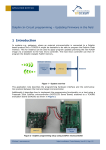
2 Demo system
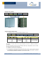
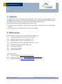
To reproduce our demo scenario following components are required:
Setup:
EVA300-3 with a module containing GatewayCtrl firmware (A)
EVA300-3 with RemanESP3 firmware (B)
DolphinView (3.1.1.0 or newer) application on PC
DolphinAPI (2.2.1.0 or newer)
USB
B
RemanESP3
A
GatewayCtrl
(as gateway)
USB
(our firmware)
Step-by-step:
1. Copy the DolphinView.Modules.APIExamples.dll to DolphinView directory.
2. Download the GatewayCTRL firmware to the module A (using DolphinView)
3. Copy the RemanESP3 to the Example directory of the installed DolphinAPI
4. Compile the firmware and download it to module B
5. Disconnect the EVA board of module B from the programmer and provide power to
the EVA using the J1 USB port
6. Start DolphinView, select serial port of EVA board and pres Connect
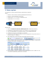
7. Press a PTM200 switch several times. The telegrams should appear in DolphinView
telegram view window. The gateway works.
8. Press QueryID to query our Advanced RemoteManagement device. NOTE: The device will be automatically locked after 30 minutes.
© EnOcean | www.enocean.com
Subject to modifications | Jozef Hopko | June 2011 | Page 4/ 20
APPLICATION NOTE 503
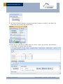
9. Our device should respond to the QueryID and it should be visible in the Node List.
Select the device using left mouse click.
10. Now we can read the ID table from the device. Select the module „API Example:
RemanESP3‟ and press „Read ID Table‟.
© EnOcean | www.enocean.com
Subject to modifications | Jozef Hopko | June 2011 | Page 5/ 20
APPLICATION NOTE 503
„Read ID Table‟ function sends the RM_FN_IDTABLE_READ message to the selected
device. We already selected the device in step 4.
Now you can modify the ID Table and write it back to our device. Note that the „Count‟ value is also important as it defines how many ID entries are valid.
There is much more functionality of remote management embedded in the application as
for instance all the remote management control commands (RMCC) as unlock, set-code,
lock, action, ping, query function, etc. The functionality is implemented but not described in
this document. The functionality can be demonstrated using the Remote Management tab
in DolphinView.
© EnOcean | www.enocean.com
Subject to modifications | Jozef Hopko | June 2011 | Page 6/ 20
APPLICATION NOTE 503
3 Demo application explained
The demo application provides similarly functionality as TCM300 in Mode 3. However the
source code is not based on TCM300 project but is completely rewritten and unlike TCM300
it uses task based approach. Following features are implemented:
2-channel relay
Bidirectional radio to serial gateway
Teach-in capability for up to 30 entries
Remote management
Additionally to Mode 3 functionality the application also implements:
Advanced RemoteLearn
ESP2 and ESP3 protocol
At this point we briefly explain what the difference between standard RemoteLearn and Advanced RemoteLearn is. RemoteLearn as specified in EnOcean System Specification allows
to „press Learn button‟ by remote command. That means the TCM300 only switches to learn
mode and the user has to press PTM200 switch manually.
To demonstrate the possibilities of remote management we introduced the Advanced Remote Learn concept. Behind the scene a custom RPC was added to allow remote access to
id_table. In id_table the information about learned-in rockers are stored. Providing remote
access to the id_table enables us to remove or learn-in new rocker switches without physically pressing the PTM200 switch buttons. We can also download or upload the whole
id_table per remote. This way we could even backup the whole building setup. In case that
a TCM300-like device fails it can be easily replaced and the corresponding id_table can be
uploaded in no-time.
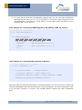
3.1 Data model
Before we describe the functional block of our demo application we take a look at data
structures used. The most important data structure is the id_table. It stores all information
about rockers switches learned-in.
Code (mod_id.h):
typedef struct
{
uint8
uint8
uint8
uint32
} ID_ENTRY_TYPE;
ID_ENTRY_TYPE
© EnOcean | www.enocean.com
u8Rocker;
u8Channel;
u8Choice;
u32Id;
id_table[ID_MAX_COUNT];
Subject to modifications | Jozef Hopko | June 2011 | Page 7/ 20
APPLICATION NOTE 503
Example of id_table[]:
Index
0
1
u8Rocker
0x00
0x02
u8Choice
0xA3
0xA3
u32Id
0x12345678
0x12345678
PTM200
u8Channel
0x00
0x01
EVA300-3
Switch scenario step-by-step:
1. The PTM200 rocker is pressed and RPS telegram is sent:
Choice
0xA3
Rocker
0x30
Bit.7
Bit.6
Bit.5
Rocker 1st action
0: AI
1: A0
2: BI
3: B0
0x12
0x34
Bit.4
Energy bow
0: Released
1: Pressed
ID
0x56
0x78
Bit.3
Bit.2
Bit.1
Rocker 2nd action
0: AI
1: A0
2: BI
3: B0
Status
0x00
Bit.0
2nd action
0: no 2nd action
1: 2nd action valid
The „Rocker 1st action value‟ is the only information we store in u8Rocker attribute in
id_table[].
For more information about the RPS telegram data byte interpretation refer to EnOncean Equipment Profile documentation.
2. Telegram is received by our application.
3. The id_table[] is searched for all entries that match rocker, choice and ID. The LSB
of u8Rocker byte signalizes whether a O or I on the rocker was pressed. Therefore
when comparing u8Rocker information a 0xFE mask is used.
© EnOcean | www.enocean.com
Subject to modifications | Jozef Hopko | June 2011 | Page 8/ 20
APPLICATION NOTE 503
4. For each entry found the corresponding channel pins are set. The LSB of u8Rocker
specifies the pin value (0 or 1). So if we press “I” on the left rocker the LED on CH0
is switchen ON – pin is set to 1. If we press “I” on the right rocker the LED on CH1 is
switchen ON – pin is set to 1.
Code snippet for converting a RPS telegram to ID_ENTRY_TYPE (id_mod.c):
// In function: id_convTel(..)
switch (tel->raw.bytes[0])
{
case RADIO_CHOICE_RPS:
entry->u8Rocker = tel->trps.u8Data >> 5;
entry->u32Id
= tel->trps.u32Id;
*u8Pressed
= (tel->trps.u8Data >> 4) & 1;
*u8Value
= (tel->trps.u8Data >> 5) & 1;
break;
Code snippet for controlling the channels (switch.c):
// Set all channels from id_table
for (i=0; i<u8IdCount; i++)
{
if ( id_table[i].u32Id
== entry.u32Id &&
id_table[i].u8Choice == entry.u8Choice &&
(id_table[i].u8Rocker & 0xFE) == (entry.u8Rocker & 0xFE))
channel_set(id_table[i].u8Channel, bValue);
}
This code sets the channels according to received telegram. The entry structure contains all
required information that was extracted from received telegram. For more information refer
to id_convTel() function in id_mod.c. The variable bValue contains the LSB of u8Rocker
byte.
© EnOcean | www.enocean.com
Subject to modifications | Jozef Hopko | June 2011 | Page 9/ 20
APPLICATION NOTE 503
3.2 Tasks
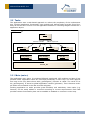
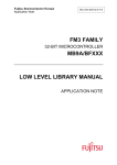
The application uses a task based approach to reduce the complexity of the implementation. Dividing application functionality into multiple well defined tasks provides more flexibility as well as more control over the application behaviour. Following diagram shows the 3
application layers.
cmp Application
main.c
execute
execute
execute
execute
Tasks
gatew ay.c
learn.c
remote.c
sw itch.c
Modules
mod_button.c
mod_channel.c
mod_id.c
EO3000I_API
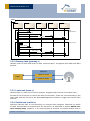
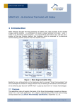
3.2.1 Main (main.c)
The application entry point. It initializes EO3000I peripherals, API modules and also all application tasks. Application tasks are executed periodically in main loop. The main application loop is the only place where radio_getTelegram() function is called. The result of radio_getTelegram() is stored to global application context (gContext). This is because multiple tasks are interested in the last received telegram.
Dividing application to tasks provides great flexibility and modularity. New tasks (e.g.
Dimmer) can be easily added or removed according to current requirements. Each task
provides custom functionality that can be enabled or disabled on runtime in main loop.
© EnOcean | www.enocean.com
Subject to modifications | Jozef Hopko | June 2011 | Page 10/ 20
APPLICATION NOTE 503
sd Main
Main()
switch.c
remote.c
learn.c
gateway.c
Task
initalialization
switch_init()
remote_init()
learn_init()
gateway_init()
Task execution
*while (1)
switch_exec()
remote_exec()
learn_exec()
gateway_exec()
3.2.2 Gateway task (gateway.c)
Handles radio to serial and serial to radio communication. It supports both ESP2 and ESP3
protocol.
EO3000I
UART
radio to serial
serial to radio
Radio
3.2.3 Learn task (learn.c)
Handles learn-in, learn-out of rocker switches. Supports both manual and remote learn.
Provides a set of function to control the learn functionality. These are used internally by the
Learn task itself as well as by the RemoteManagement module to trigger the remote learn
function.
3.2.4 Switch task (switch.c)
Switches channels CH0 to CH4 according to received radio telegram. Searches the whole
id_table and operates all channels that are learned-in as described in section Switch scenario step-by-step, chapter 2.1. If a new telegram is received, the switch module looks in
© EnOcean | www.enocean.com
Subject to modifications | Jozef Hopko | June 2011 | Page 11/ 20
APPLICATION NOTE 503
the id_table. If an entry that corresponds to received telegram is found then the channel is
switched on/off.
3.2.5 Button module (mod_button.c)
The module provides structures and functions for capturing a push button input. The
btn_getState() function is a state machine that captures input from physical pin and transforms it into button state. The state machine can filter peaks or bad contacts on the push
button.
3.2.6 IDTable Management module (mod_id.c)
This module defines data structures required for switch and learn functionality. The id_table
contains all information about rocker switches learned-in. The module also provides a set of
functions to alter the id_table. These functions are used by Learn module.
3.2.7 Channel module (mod_channel.c)
Defines a hardware abstraction layer. Specific I/O ports (like SCSEDIO_0, WSDADIO_2) are
mapped to logical channels like CH0 to CH3. The module defines a set of functions to control output channels.
An advantage of this abstraction is the flexibility of implementation. If the hardware
changes or the count of logical channels is reduced or extended the overlaying implementation needn't be changed.
3.2.8 RemoteManagement task (remote.c)
Processes remote management messages and responds to RMCC's and RPC's. Currently all
standard RMCC's are supported. Also following RPCs are supported:
RM_FN_REMOTE_READ
RM_FN_REMOTE_WRITE
RM_FN_REMOTE_LEARN
RM_FN_IDTABLE_READ
RM_FN_IDTABLE_WRITE
The remote read, write and learn are standard RPCs specified in EnOcean System Specification. The remote 'IDTable read and write' (RM_FN_IDTABLE_READ,
RM_FN_IDTABLE_WRITE) are a custom RPCs defined for this example. It demonstrates
advanced remote learn concept as well as the remote management usage. When pressing
the CLR button not only the ID table will be cleared but also the REMAN code is deleted.
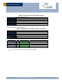
3.3 Remote command RM_FN_IDTABLE_READ
For the demo purposes we have defined a custom RPC called RM_FN_IDTABLE_READ. Using this RPC we are able to read the whole id_table.
NOTE: ID_ENTRY is an ID_ENTRY_TYPE structure defined in io_mod.h.
This RPC‟s is not standardized therefore not part of the EEP2.1 specification!
© EnOcean | www.enocean.com
Subject to modifications | Jozef Hopko | June 2011 | Page 12/ 20
APPLICATION NOTE 503
Table 1 IDTable read command description
Command
Function code
ManufacturerID
Datalength
Broadcast
Addressable
Answer
RM_FN_IDTABLE_READ
0x207
0x00B
0
NO
YES
YES
Message data description:
N/A – the message is has no data
Table 2 IDTable read command answer description
Command
Function code
ManufacturerID
Datalength
Broadcast
Addressable
Answer
RM_FN_IDTABLE_READ_ANS
0x807
0x00B
1+7*N where N is the count of the ID entries in the ID_TABLE
NO
YES
YES
Answer data description:
Offset
0
1
8
..
1+7*Count
Size
1
7
7
..
7
Field
Count
ID_ENTRY
ID_ENTRY
..
ID_ENTRY
Description
The count of the ID_ENTRY items
ID_ENTRY item
ID_ENTRY item
..
ID_ENTRY item
The “n” is the count of id entries in the id_table[].
© EnOcean | www.enocean.com
Subject to modifications | Jozef Hopko | June 2011 | Page 13/ 20
APPLICATION NOTE 503
3.4 Remote command RM_FN_IDTABLE_WRITE
Similarly to RM_FN_IDTABLE_READ we defined the function RM_FN_IDTABLE_WRITE. Using this RPC we are able to write the whole id_table.
NOTE: ID_ENTRY is an ID_ENTRY_TYPE structure defined in io_mod.h.
This RPC‟s is not standardized therefore not part of the EEP2.1 specification!
Table 3 IDTable write command description
Command
Function code
ManufacturerID
Datalength
Broadcast
Addressable
Answer
RM_FN_IDTABLE_WRITE
0x208
0x00B
0
NO
YES
YES
Message data description:
Offset
0
1
8
..
1+7*Count
Size
1
7
7
..
7
Field
Count
ID_ENTRY
ID_ENTRY
..
ID_ENTRY
Description
The count of the ID_ENTRY items
ID_ENTRY item
ID_ENTRY item
..
ID_ENTRY item
The “N” is the count of id entries in the id_table[].
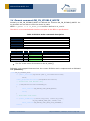
Following code snipped illustrates how the remote IDTable read is implemented on EO3000I
side (remote.c):
case RM_FN_IDTABLE_READ:
if (!misc_isLocalId(&gContext.pTel.p_rx.u32DestinationId))
break;
reman_getRpcManufacturerID(&u16RpcManufacturerID);
// Process RPC from EnOcean only
if (u16RpcManufacturerID!=ENOCEAN_ID)
{
reman_setError(RM_RETURN_CODE_WRONG_MANID);
break;
}
// Read table from flash
if (reman_sendMessage((uint8*)&id_table, sizeof(id_table),
RM_FN_IDTABLE_READ_ANS, FALSE)!=OK)
reman_setError(RM_RETURN_CODE_DATA_SIZE_EXCEEDED);
break;
© EnOcean | www.enocean.com
Subject to modifications | Jozef Hopko | June 2011 | Page 14/ 20
APPLICATION NOTE 503
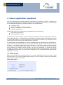
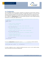
3.5 Configuration
The RemanESP3 application provides a possibility of configuring several firmware parameters. In generally it is an advantage to provide a configuration interface. The user can then
configure selected parameters of the final product without modifying the original firmware.
The configuration parameters are stored in the Configuration Area. The configuration structure is defined in configuration.h. For demonstration purposes we have defined following
parameters in the APP_CFG_AREA structure:
// Structure of software configuration bytes in application section of CFG area\n
// Located in CFG-Area starting address 0x80
typedef struct
{
// Serial Protocol Configuration
// Located in CFG-Area 0x80
// Default 0xFF: ESP3, 0x02: ESP2, other values: ESP3
uint8 u8SerialProtocol;
// Time [ms] after the output pin toggles during the learn mode.
// Located in CFG-Area 0x81 \n
// Default: 1000ms, all other values: time in milliseconds
uint16 u16LearnToggleCyclus;
// Time [ms] within the PTM switch has to be pressed 3 times to
// learn-in during remote learn.
// Located in CFG-Area 0x83 \n
// Default: 2000ms, all other values: time in milliseconds
uint16 u16LearnTime;
} APP_CFG_AREA;
In the file configuration.c the position of the APP_CFG_AREA structure in flash is defined:
//!Definition of the application configuration of the application
APP_CFG_AREA xdata gAppCfg
_at_ (CFG_ADDR+128);
In order to enable the user to modify this defined structure we can use the Modul configuration functionality provided by DolphinStudio.
© EnOcean | www.enocean.com
Subject to modifications | Jozef Hopko | June 2011 | Page 15/ 20
APPLICATION NOTE 503
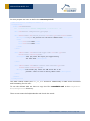
For this purpose we have to define the remanesp3.xml:
<?xml version="1.0" encoding="iso-8859-1" ?>
<configuration>
<module name="RemanESP3">
<!--
***************
General configuration
**************
-->
<data name="General configuration" type="group" />
<data address="0x80" name="Serial protocol" size="01" type="int" default="0xFF">
<description>Configure the protocol for the serial communication</description>
<enum>
<item value="0xFF">ESP3</item>
<item value="0x02">ESP2</item>
</enum>
</data>
<data address="0x81" name="Learn mode toggle time" size="02" type="int"
default="1000" formatstring="%d">
<description>Time [ms] after the output pin toggles during
the learn mode.</description>
</data>
<data address="0x83" name="Remote learn-in time" size="02" type="int"
default="2000" formatstring="%d">
<description>Time window [ms] within the PTM switch has to be
pressed 3 times to learn-in during remote learn.</description>
</data>
</module>
</configuration>
This XML reflects exactly the APP_CFG_AREA structure. Additionally it adds some comments
and formatting for the user.
To use the defined XML we have to copy the file remanESP3.xml to the DolphinStudio\Configuration directory.
Then we can start the DolphinStudio and check the result:
© EnOcean | www.enocean.com
Subject to modifications | Jozef Hopko | June 2011 | Page 16/ 20
APPLICATION NOTE 503
Now we can easily modify the parameters and press „Write configuration‟ button to write
the configuration to the module.
NOTE: The remote learn-in time of 2000ms is standard for all EnOcean products. Changing
this parameter is used for demonstration purposes only! It is not recommended to allow the
change of this parameter for final products.
© EnOcean | www.enocean.com
Subject to modifications | Jozef Hopko | June 2011 | Page 17/ 20
APPLICATION NOTE 503
4 Demo Limitations
The demonstration has several limitations mainly to reduce the complexity and therefore
increase the ease of understanding.
The remote commands RM_FN_IDTABLE_READ and RM_FN_IDTABLE_WRITE are not
standard commands defined in EEP 2.1. It should not be used as end-product solution.
The rocked 2
nd
action is not supported.
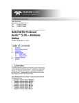
4.1 Repeater level in remote management
When using TCM300 as gateway the telegram repeater status should be considered. Following scenario shows what happens when sending QueryID telegram from PC with repeater
status set to 0.
Setup:
1. PC – Computer running application like DolphinView
2. Device A – radio to serial gateway
3. Device B – device we want to control per remote management
Step-by-step:
DolphinView sends QueryID telegram over serial, repeater status is 0.
Device A receives serial telegram and forwards it to radio.
Device B replays with QueryID Answer telegram.
Device B repeats the QueryID, increases repeater status bits to 1 (R1).
Device A receives the QueryID telegram.
Device A replays witch QueryID Answer telegram.
Device A repeats the QueryID Answer, increases repeater status.
PC receives QueryID answer from device B and device A.
© EnOcean | www.enocean.com
Subject to modifications | Jozef Hopko | June 2011 | Page 18/ 20
APPLICATION NOTE 503
<- UART ->
1. QueryID, R0
Answer from B
Answer from A
<- Radio ->
A
TCM300
(as gateway)
2. QueryID, R0
3. Answer QueryID B, R0
B
TCM300
with repeater
3. QueryID, R1
4. Answer QueryID A, R0
Rn - repeater status
R0 - original telegram
R1 - telegram repeated once
5. Answer QueryID A, R1
The problem with this scenario is that we actually queried also our gateway. There are several solutions for this problem:
Use gateway software without remote management possibilities
When sending remote management telegrams from an application set the status
byte to 0xF – Telegram must not be repeated. This way the repeaters will not repeat
the telegrams again. In some scenarios this also reduces the radio traffic.
Filter the remote management answers with gateway ID on application side.
© EnOcean | www.enocean.com
Subject to modifications | Jozef Hopko | June 2011 | Page 19/ 20
APPLICATION NOTE 503
5 Outlook
This application note demonstrated the operation of a remote managed application with
TCM300 like functionality. The provided software and documentation shall make it easy to
get familiar with the topic and starting own development based on this.
Further optimizations on the software side could e.g. be
The structure of ID_ENTRY_TYPE should be reviewed to cover various rocker switch sce-
narios.
Add dimmer task to support dimmer switch functionality
6 References
Further details can be found in the following documentation
[1.]
Remote Management specification, 19.02.2010
[2.]
EnOcean Serial Protocol 2 specification, v2.5
[3.]
EnOcean Serial Protocol 3 specification, v1.4
[4.]
DolphinAPI user manual, EO3000I_API.chm, 2.0.0.0
[5.]
EnOcean Equipment Profiles (EEP), V2.1
[6.]
Schematics EVA300-3
[7.]
TCM300 User Manual
[8.]
TCM300 Data Sheet
Useful web sites:
[9.]
EnOcean website http://www.enocean.com
[10.]
EnOcean Alliance website http://www.enocean-alliance.org
[11.]
Wikipedia website http://www.wikipedia.org/
© EnOcean | www.enocean.com
Subject to modifications | Jozef Hopko | June 2011 | Page 20/ 20