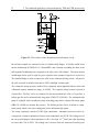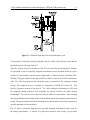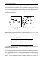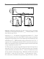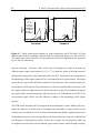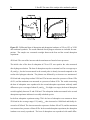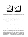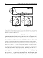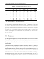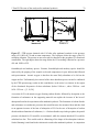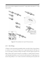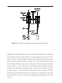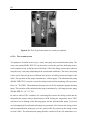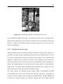
1
The coverage-dependent adsorption of carbon
monoxide on copper catalysts studied by a
combination of adsorption microcalorimetry,
temperature-programmed desorption and Fourier
transform infrared spectroscopy
DISSERTATION
zur Erlangung des Grades
eines Doktors der Naturwissenschaften
vorgelegt von
Raoul Naumann d’Alnoncourt
aus Göttingen
Ruhr-Universität Bochum
Lehrstuhl für Technische Chemie
2005
Die vorliegende Arbeit wurde in der Zeit vom Dezember 2001 bis Dezember 2004 am Lehrstuhl
für Technische Chemie der Ruhr-Universität Bochum angefertigt.
Vorsitzender der Prüfungskommission: Prof. Dr. Ch. Wöll
Referent: Prof. Dr. M. Muhler
Korreferent: Prof. Dr. W. Grünert
Dritter Prüfer: Prof. Dr. R. Fischer
Tag der mündlichen Prüfung: 31. Januar 2005
Danksagung
Mein besonderer Dank gilt Prof. Dr. Martin Muhler für die wissenschaftliche Leitung dieser
Arbeit, für sein stetes Interesse und seine Geduld.
Prof. Dr. Wolfgang Grünert danke ich für die Übernahme des Korreferats.
Den Mitgliedern der Methanol-Gruppe möchte ich für die gute Zusammenarbeit danken:
Elke, Hagen, Jenny, Lamy, Maurits, Melanie und Olaf.
Vielen Dank dem technischen und administrativen Personal des Lehrstuhls, ohne deren Hilfe
die Doktorarbeit nicht möglich gewesen wäre:
Astrid, Heinz, Manuela, Sandy, Sigrid und Sigrid, Susanne und die Herren Otto.
Ich möchte an dieser Stelle auch den Werkstätten der Fakultät Chemie der RUB danken.
Ich bedanke mich bei meinen Eltern, die mich während meines gesamten Studiums immer voll
und ganz unterstützt haben.
Vielen Dank an Silke für Hilfe und Unterstützung, im Alltag wie in besonderen Zeiten.
Vielen Dank auch an Euch:
Wilma, Markus, Obi Wan Volker, die Ethanolgruppe ...
Contents
1
Introduction
1
2
The combined application of microcalorimetry, TPD and FTIR spectroscopy
9
2.1
Introduction . . . . . . . . . . . . . . . . . . . . . . . . . . . . . . . . . . . .
9
2.2
Experimental . . . . . . . . . . . . . . . . . . . . . . . . . . . . . . . . . . . 11
2.3
2.4
3
4
2.2.1
Adsorption microcalorimetry . . . . . . . . . . . . . . . . . . . . . . . 11
2.2.2
CO TPD experiments . . . . . . . . . . . . . . . . . . . . . . . . . . . 15
2.2.3
Transmission FTIR spectroscopy . . . . . . . . . . . . . . . . . . . . . 16
2.2.4
Investigated samples . . . . . . . . . . . . . . . . . . . . . . . . . . . 17
Results and discussion . . . . . . . . . . . . . . . . . . . . . . . . . . . . . . 18
2.3.1
Calorimetry . . . . . . . . . . . . . . . . . . . . . . . . . . . . . . . . 18
2.3.2
CO TPD results . . . . . . . . . . . . . . . . . . . . . . . . . . . . . . 20
2.3.3
Results by FTIR spectroscopy . . . . . . . . . . . . . . . . . . . . . . 22
Conclusions . . . . . . . . . . . . . . . . . . . . . . . . . . . . . . . . . . . . 24
Part I: The reduced catalyst
27
3.1
Introduction . . . . . . . . . . . . . . . . . . . . . . . . . . . . . . . . . . . . 27
3.2
Experimental . . . . . . . . . . . . . . . . . . . . . . . . . . . . . . . . . . . 28
3.3
Results . . . . . . . . . . . . . . . . . . . . . . . . . . . . . . . . . . . . . . . 30
3.4
Discussion . . . . . . . . . . . . . . . . . . . . . . . . . . . . . . . . . . . . . 35
3.5
Conclusions . . . . . . . . . . . . . . . . . . . . . . . . . . . . . . . . . . . . 43
Part II: The state of the catalyst after pretreatment in CO
47
4.1
Introduction . . . . . . . . . . . . . . . . . . . . . . . . . . . . . . . . . . . . 47
4.2
Experimental . . . . . . . . . . . . . . . . . . . . . . . . . . . . . . . . . . . 49
4.3
Results . . . . . . . . . . . . . . . . . . . . . . . . . . . . . . . . . . . . . . . 51
4.4
Discussion . . . . . . . . . . . . . . . . . . . . . . . . . . . . . . . . . . . . . 56
4.5
Conclusions . . . . . . . . . . . . . . . . . . . . . . . . . . . . . . . . . . . . 64
IV
5
6
Contents
Part III: The state of the catalyst after methanol synthesis
69
5.1
Introduction . . . . . . . . . . . . . . . . . . . . . . . . . . . . . . . . . . . . 69
5.2
Experimental . . . . . . . . . . . . . . . . . . . . . . . . . . . . . . . . . . . 70
5.3
Results . . . . . . . . . . . . . . . . . . . . . . . . . . . . . . . . . . . . . . . 72
5.4
Discussion . . . . . . . . . . . . . . . . . . . . . . . . . . . . . . . . . . . . . 77
5.5
Conclusions . . . . . . . . . . . . . . . . . . . . . . . . . . . . . . . . . . . . 81
Conclusions
85
6.1
Introduction . . . . . . . . . . . . . . . . . . . . . . . . . . . . . . . . . . . . 89
6.2
Experimental . . . . . . . . . . . . . . . . . . . . . . . . . . . . . . . . . . . 90
6.2.1
6.2.2
6.2.3
Connectors and flanges . . . . . . . . . . . . . . . . . . . . . . . . . . 90
6.2.1.1
Swagelok connectors and tube fittings . . . . . . . . . . . . 90
6.2.1.2
The Cajon VCR connection . . . . . . . . . . . . . . . . . . 91
6.2.1.3
The CF Flange . . . . . . . . . . . . . . . . . . . . . . . . . 93
6.2.1.4
The KF Flange . . . . . . . . . . . . . . . . . . . . . . . . . 94
The adsorption microcalorimetry set-up . . . . . . . . . . . . . . . . . 94
6.2.2.1
The microcalorimeter . . . . . . . . . . . . . . . . . . . . . 95
6.2.2.2
The volumetric dosing section . . . . . . . . . . . . . . . . . 96
6.2.2.3
Controlling the temperature of the set-up . . . . . . . . . . . 98
6.2.2.4
The measuring cells . . . . . . . . . . . . . . . . . . . . . . 99
6.2.2.5
The gas supply system . . . . . . . . . . . . . . . . . . . . . 100
6.2.2.6
The vacuum system . . . . . . . . . . . . . . . . . . . . . . 102
6.2.2.7
The Baratron pressure gauges . . . . . . . . . . . . . . . . . 103
Operation of the adsorption microcalorimetry set-up . . . . . . . . . . 104
6.2.3.1
Controlling the calorimeter via the Setsoft 2000 software . . 104
6.2.3.2
Controlling the volumetric dosing section via LabView programs . . . . . . . . . . . . . . . . . . . . . . . . . . . . . 107
6.3
6.2.3.3
Volume calibration . . . . . . . . . . . . . . . . . . . . . . . 111
6.2.3.4
Sample pretreatment . . . . . . . . . . . . . . . . . . . . . . 113
6.2.3.5
Measurement of heats of adsorption . . . . . . . . . . . . . . 115
Data processing . . . . . . . . . . . . . . . . . . . . . . . . . . . . . . . . . . 116
Contents
V
6.3.1
Calculation of the adsorption isotherm . . . . . . . . . . . . . . . . . . 117
6.3.2
Calculation of the differential heat of adsorption . . . . . . . . . . . . 120
1
Introduction
Methanol is together with ammonia and sulphuric acid one of the three most important products
synthesized industrially. Copper catalysts are widely used for the synthesis of methanol. The
industrially applied catalyst is a ternary system containing copper (Cu), zinc oxide (ZnO), and
alumina (Al2 O3 ) [1, 2]. Although this catalyst system has been used for about 40 years and
in spite of the importance of the methanol synthesis process, the nature of the active site, the
role of the different catalyst components and the mechanism of the methanol synthesis are still
subject of investigations.
Klier [3] proposed copper species incorporated in interstitial and substitutional sites in ZnO to
be the active site in methanol synthesis. Okamoto et al. [4] correlated the activity of Cu/ZnO
catalysts to Cu0 -Cu+ species in a two-dimensional epitaxial layer on ZnO. Other authors [5, 6]
identified copper in its metallic state as the active site and ZnO as inert supporting material
that stabilizes a high copper surface [5]. Frost [7] assumed that the active sites are located at
the Cu/ZnO interface. Nakamura and co-workers [8, 9, 10] reported that ZnOx species migrated under reducing conditions onto the Cu surfaces forming Cu-Zn alloys and stabilizing
Cu(I) species. Clausen et al. [11, 12] found no experimental evidence for Cu(I) species when
investigating Cu/ZnO/Al2 O3 samples in an in situ X-ray diffraction (XRD) and an in situ Xray absorption fine structure (XAFS) study under the conditions of methanol synthesis while
measuring the catalytic activity using on-line gas chromatography. X-ray photoelectron spectroscopy (XPS) data presented by Fleisch and Mieville [13] included also no evidence for Cu(I)
species under methanol synthesis conditions.
Chinchen et al. [14] investigated the synthesis of methanol from
14
C-labelled reactants over
Cu/ZnO/Al2 O3 . The authors concluded that methanol is predominantly produced from carbon
dioxide (CO2 ) and not from carbon monoxide (CO) for a wide range of CO2 /CO ratios in the
feed gas. Askgaard et al. [15] presented a detailed kinetic model of the methanol synthesis
over copper catalysts based on surface science studies. In their model methanol is synthesized
from carbon dioxide only. Adsorbed carbon dioxide is hydrogenated to methanol and water
via formate as stable intermediate product. The model includes the water-gas shift reaction of
carbon monoxide and water and a route from formate to formaldehyde as by-product.
2
1 Introduction
Carbon monoxide is an often used probe molecule. In literature, many studies are found
investigating copper, binary (e. g.
Cu/ZnO, Cu/Al2 O3 ) or ternary copper catalysts (e. g.
Cu/ZnO/Al2 O3 ) by microcalorimetry, temperature-programmed desorption (TPD) or Fourier
transform infrared (FTIR) spectroscopy.
In 1934, Beebe and Wildner [16] measured calorimetrically the heat of adsorption of CO on
reduced copper granules. They observed a decrease with increasing coverage from an initial
value of about 85 kJ/mol to a value of about 57 kJ/mol at a pressure of about 50 Pa of CO.
Tracy [17] measured the isosteric heat of adsorption of CO on the Cu(100) single crystal plane
and reported values of about 70 kJ/mol at low coverage and 56 kJ/mol at high coverage. Hollins
and Pritchard [18] reported isosteric heats of adsorption of CO on Cu(111) of 50 and 38 kJ/mol
at low and high coverage, respectively. More recently, Vollmer et al. [20] derived site-specific
adsorption energies of CO on single crystal faces and polycrystalline copper by thermal desorption spectroscopy (TDS). For the close packed surfaces Cu(111) and Cu(110), integral heats
of adsorption of 47 and 51 kJ/mol, respectively, were determined. Higher values of 58 kJ/mol
were found for kinks, steps, and defect structures.
In an FTIR study Dulaurent et al. [19] found a band at 2092 cm−1 after the adsorption of CO
on a completely reduced 4.7 % Cu/Al2 O3 at 300 K for pressures of 1 and 10 kPa. They reported
isosteric heats of adsorption of 82 kJ/mol at low coverages and 57 kJ/mol at high coverages.
Boccuzzi et al. [21] investigated the adsorption of CO on Cu/ZnO catalysts by FTIR spectroscopy. They observed a strong and narrow band at 2098 cm−1 and a broad and weak band at
2070 cm−1 after the adsorption of CO on the reduced catalyst. Giamello et al. [22] presented
a microcalorimetric study of the adsorption of CO on Cu/ZnO. They assigned heats of adsorption of about 300–110 kJ/mol to the adsorption of CO on Cu(II) species, heats of adsorption in
the range from 110–70 kJ/mol to the adsorption on Cu(I) species, and heats of adsorption of
70–40 kJ/mol to the adsorption on Cu(0).
1975 Pritchard et al. [23] presented an infrared spectroscopy study of carbon monoxide
chemisorbed on copper. The authors compared own data and literature data concerning copper
single crystals and copper catalyst samples with various supports. The frequency of the stretching vibration of adsorbed CO is significantly different for different copper single crystal planes.
The frequency is lower for low-indexed single crystal planes than for high-indexed planes, i. e.
2085, 2076 and 2093 cm−1 for Cu(100), Cu(111) and Cu(110) and 2100, 2102 and 2098 cm−1
1 Introduction
3
for Cu(211), Cu(311) and Cu(755). It is interesting to note that only the high-frequency bands
were observed in the case of supported copper (evaporated films and dispersed metal), even
though other characterization methods indicated the presence of low-indexed surface planes.
The authors stated that this effect was not due to incomplete reduction of the copper or temperature differences in the experimental conditions (77 K in the case of copper single crystal
studies, about 300 K in the case of supported copper). In 1992 Hollins [24] gave an explanation of this apparent contradiction. Dipole-dipole coupling of chemisorbed species leads to an
intensity shift from low-frequency to high-frequency bands. In the case of CO chemisorbed on
copper, this intensity shift leads to an increase of the bands assigned to CO adsorbed on defect
sites (high-indexed planes, high-frequency bands) and a decrease of the bands assigned to CO
on terrace sites (low-indexed planes, low-frequency bands). Hollins showed that the resulting
spectrum can be completely dominated by the bands assigned to defect sites, even when the
defect sites are a minority species of less than 10 %.
In 1978 Tauster et al. [25] reported that the state of noble metal catalysts using TiO2 as support
depended on the reduction conditions. The investigated samples showed different behavior
in the adsorption of hydrogen and carbon monoxide after low-temperature reduction and hightemperature reduction. After low-temperature reduction all samples adsorbed hydrogen and CO
in reasonable agreement to literature data. The adsorption capacity of the samples decreased
to nearly zero after high-temperature reduction. The effect was reversible as the adsorption capacity was fully restored by an oxidizing treatment and subsequent low-temperature reduction.
Using electron microscopy and X-ray diffraction the authors showed that the loss of adsorption
capacity was not due to metal agglomeration or encapsulation. They concluded that the loss of
adsorption capacity should be related to the formation of bonds between the noble metal atoms
and titanium atoms or cations of the support, thus changing the electronic properties of the
metal clusters. They referred to these processes as strong metal-support interactions (SMSI).
Several recent studies [26, 27, 28, 29, 30] using different investigation methods indicate that
there are strong metal-support interactions (SMSI) between copper and zinc oxide in these
catalysts.
Based on in situ EXAFS and XRD experiments Grunwaldt et al. [26] presented a model for
the SMSI between copper and ZnO as a function of the surrounding atmosphere: Under the
reducing conditions of methanol synthesis, metallic copper particles spread on the support and
4
1 Introduction
their surfaces are covered by zinc and oxygen species. Under more severe conditions, i. e. in
an atmosphere of a higher reduction potential, surface and bulk alloying leads to the formation
of brass.
Hansen et al. [27] gave experimental evidence of dynamic shape changes of copper nanocrystals supported on ZnO. The changes were directly observed by in situ transmission electron
microscopy under high pressures. The effects were caused by changes of the reduction potential of the surrounding gas phase and were fully reversible. The authors concluded that the
processes were due to adsorbate-induced changes of the Cu/ZnO interfacial energies. They assumed that oxygen vacancies in the ZnO play a role in the observed processes. Only negligible
shape changes were found for copper nanocrystals supported on SiO2 .
Wagner et al. [29] investigated the SMSI between copper and ZnO by applying in situ electron
energy loss spectroscopy. They reported that the support induced a tensile strain in the Cu nanoclusters. The degree of this strain was dependent on the reduction potential of the surrounding
gas phase. They found no indication for strained Cu nanoclusters in Cu/SiO2 samples.
Hinrichsen and co-workers [28, 30] investigated the interaction of hydrogen and nitrous oxide
with Cu/Al2 O3 , Cu/ZnO and Cu/ZnO/Al2 O3 samples after different pretreatments. The applied
pretreatment conditions included reduction in hydrogen, methanol synthesis and a strongly
reducing pretreatment in CO. The authors found that Cu/Al2 O3 is hardly influenced by the
pretreatment, while dynamical changes of the copper content were found in the case of ZnOcontaining samples. The strongly reducing conditions of the pretreatment in CO led to a loss
in free copper surface area. The free copper surface area was derived from hydrogen TPD
experiments. The authors concluded that zinc and oxygen species migrated onto the copper
surface thus decreasing the free surface area. The presence of the zinc species was confirmed
by nitrous oxide reactive frontal chromatography.
It is difficult to draw conclusions from a comparison of all these studies, as the samples are
never prepared and pretreated following identical procedures. For example, Giamello et al. [22]
found in their microcalorimetric study the presence of Cu(I) species in a Cu/ZnO sample after hydrogen reduction and postulated that these species were dissolved in the ZnO matrix.
Following the authors, their results supported the role of Cu(I) species as active site in the synthesis of methanol. However, the authors also pointed out that Boccuzzi et al. [21] using FTIR
spectroscopy did not find any evidence for Cu(I) species investigating the same catalyst sample
1 Introduction
5
after a similar pretreatment.
The goal of this study is to reach a better understanding of the SMSI between copper and zinc
oxide. For several reasons the adsorption of carbon monoxide was chosen as investigation tool.
The adsorption of carbon monoxide on copper catalysts is non-dissociative and not activated,
and the stretching vibration of CO is active in FTIR spectroscopy. One single investigation
method cannot give all desired information. For example FTIR spectroscopy can be used to
identify chemically different adsorption sites, but the strength of the bond between adsorbate
and adsorption site cannot be directly measured. On the other hand, microcalorimetry can
be used to measure the heat of adsorption of a specific adsorbate on a substrate, but cannot
distinguish between chemically different sites with the same heat of adsorption. Therefore, a
combination of microcalorimetry, temperature-programmed desorption experiments and FTIR
spectroscopy was applied to study the adsorption of CO. In order to obtain a high degree of
comparability with the work of Hinrichsen and co-workers [28, 30, 31], the same samples were
included in the present study. In addition, the samples were pretreated using the same set-up
and following the same procedures applied in ref. [28, 30]. The building of a microcalorimetry
set-up including a special pretreatment reactor that can be attached to the flow set-up used
for the TPD experiments was one of the main tasks in this study. In addition, an already
existing FTIR cell was modified to allow pretreatments in flowing gas and the dosing of CO at
pressures below 100 Pa. The FTIR cell was also connected to the flow set-up used for the TPD
experiments. All these efforts were made to avoid the problems that arise when data produced
with different or differently pretreated samples are compared.
A complete description of the set-up and all experimental conditions is given in the second
chapter. Analogous to the work in ref. [28, 30], the catalyst samples were studied after three
different pretreatments: after a complete reduction of the copper content of the sample in hydrogen, after a 12 h period of methanol synthesis and after a 50 h pretreatment in strongly reducing
CO gas. The results obtained with all samples after a specific pretreatment are presented in one
chapter, respectively. The final chapter summarizes the conclusions of each chapter.
Bibliography
[1] J.B. Hansen,in: ”Handbook of Heterogenous Catalysis”, VCH Verlagsgesellschaft, Weinheim, 4 (1997) 1856.
[2] K. Kochloefl,in: ”Handbook of Heterogenous Catalysis”, VCH Verlagsgesellschaft,
Weinheim, 4 (1997) 1831.
[3] K. Klier, Adv. Catal., 31 (1982) 243.
[4] Y. Okamoto, K, Fukino, T. Imanaka, and S. Teranishi, J. Phys. Chem., 87 (1983) 3747.
[5] G.C. Chinchen, K.C. Waugh and D.A. Whan, Appl. Catal., 25 (1986) 101.
[6] J.L. Robbins, E. Iglesia, C.P. Kelkar, and B. DeRites, Catal. Lett., 10 (1991) 1.
[7] J.C. Frost, Nature, 334 (1988) 577.
[8] I. Nakamura, T. Fujitani, T. Uchijima, and J. Nakamura, J. Vac. Sci. Technol. A, 14 (1996)
1464.
[9] I. Nakamura, T. Fujitani and T. Uchijima, und J. Nakamura, Surf. Sci., 400 (1998) 387.
[10] Y. Kanai, T. Watanabe, T. Fujitani, M. Saito, J. Nakamura, and T. Uchijima, Energy Convers. Mgmt, 36 (1995) 649.
[11] B.S. Clausen and H. Topsøe, Catal. Today, 9 (1991) 189.
[12] B.S. Clausen, G. Steffensen, B. Fabius, J. Villadsen, R. Feidenhans’l, and H. Topsøe, J.
Catal., 132 (1991) 524.
[13] T.H. Fleisch and R.L. Mieville, J. Catal., 90 (1984) 165.
[14] G.C. Chinchen, P.J. Denny, D.G. Parker, M.S. Spencer and D.A. Whan, Appl. Catal., 30
(1987) 333.
[15] T.S. Askgaard, J.K. Nørskov, C.V. Ovesen, and P. Stoltze, J. Catal., 156 (1995) 229.
[16] R.A. Beebe and E.L. Wildner, J. Am. Chem. Soc., 56 (1934) 642.
[17] J.C. Tracy, J. Chem. Phys., 56 (1972) 2748.
[18] P. Hollins and J. Pritchard, Surf. Sci., 89 (1979) 486.
[19] O. Dulaurent, X. Courtois, V. Perrichon, and D. Bianchi, J. Phys. Chem. B, 104 (2000)
6001.
[20] S. Vollmer, G. Witte and C. Wöll, Catal. Lett., 77 (2001) 97.
[21] F. Boccuzzi, G. Ghiotti and A. Chiorino, Surf. Sci., 156 (1985) 933.
8
Bibliography
[22] E. Giamello, B. Fubini and V. Bolis, Appl. Catal., 36 (1988) 287.
[23] J. Pritchard, T. Catterick and R.K. Gupta, Surf. Sci., 53 (1975) 1.
[24] P. Hollins, Surf. Sci. Rep., 16 (1992) 53.
[25] S.J. Tauster, S.C. Fung and R.L. Garten, J. Am. Chem. Soc., 100 (1978) 170.
[26] J.-D. Grunwaldt, A.M. Molenbroek, N.-Y. Topsøe, H. Topsøe, and B.S. Clausen, J. Catal.,
194 (2000) 452.
[27] P.L. Hansen, J.B. Wagner, S. Helveg, J.R. Rostrup-Nielsen, B.S. Clausen, and H. Topsøe,
Science, 295 (2002) 2053.
[28] H. Wilmer and O. Hinrichsen, Catal. Lett., 82 (2002) 117.
[29] J.B. Wagner, P.L. Hansen, A.M. Molenbroek, H. Topsøe, B.S. Clausen, and S. Helveg, J.
Phys. Chem. B, 107 (2003) 7753.
[30] H. Wilmer, T. Genger and H. Hinrichsen, J. Catal., 215 (2003) 188.
[31] M. Kurtz, H. Wilmer, T. Genger, O. Hinrichsen, and M. Muhler, Catal. Lett., 86 (2003)
77.
2
The combined application of
microcalorimetry, TPD and FTIR
spectroscopy
Abstract
The strong metal-support interactions between Cu and ZnO are strongly influenced by the pretreatment of the Cu/ZnO catalysts. The objective of this contribution is to demonstrate that by
pretreating binary Cu/ZnO and ternary Cu/ZnO/Al2 O3 samples under the same conditions, the
Cu metal surface in identical states is accessible to adsorption microcalorimetry, TPD experiments and transmission FTIR spectroscopy. Carbon monoxide is used as probe molecule to
investigate the state of the Cu surface after H2 reduction. All results show that a fully reduced
and adsorbate-free Cu surface is obtained after a reduction pretreatment in flowing hydrogen.
The adsorption of CO on these surfaces is fully reversible at room temperature, with heats of
adsorption ranging between 70 kJ/mol at low coverages and 45 kJ/mol at high coverages.
2.1 Introduction
Copper catalysts are widely used for the industrial methanol synthesis. These catalysts are
ternary systems containing copper, zinc oxide and alumina [1]. Several recent studies indicate
there are strong metal-support interactions (SMSI) between copper and zinc oxide in these
catalysts. Under the reducing conditions of the methanol synthesis, the metallic copper surfaces
are covered by zinc and oxygen species [2]. Under more severe conditions, surface and bulk
alloying leads to the formation of brass [3]. The adsorption of CO can be applied as a tool to
investigate the nature of the SMSI effect.
In this contribution, three different techniques are used to study the adsorption of CO on copper
catalysts, which are linked by the same gas supply and gas analysis units for sample pretreatment. The goal of this contribution is to demonstrate that by pretreating samples under the same
10
2 The combined application of microcalorimetry, TPD and FTIR spectroscopy
conditions, the metallic copper surface is accessible to the different investigation methods in
identical states.
The heat of adsorption can be derived from temperature programmed desorption (TPD) experiments using the Redhead equation, or from adsorption isotherms using the Clausius-Clapeyron
equation. A more direct approach is to measure the differential heat of adsorption as a function of coverage by adsorption microcalorimetry. The value of this tool for the characterization
of catalyst surfaces is demonstrated in numerous examples in literature, focusing e. g. on acid
sites in zeolites or on metal oxide surfaces [4, 5]. Spiewak and Dumesic [6] presented a technique, which allows to study reactive catalyst surfaces unimpaired by poisoning. For example,
they applied this technique to determine the heat of adsorption of nitrogen on reduced and
extremely air-sensitive iron catalysts. Samples were pretreated ex situ in ultra-pure flowing
gases, and then sealed in pyrex capsules in inert gas. These capsules were transferred into the
calorimeter, and were broken after degassing the microcalorimetric cells. Small doses of the
adsorptive gas were subsequently admitted to the adsorbent, and while the heat of adsorption
was measured calorimetrically, the amount of adsorbed species was measured volumetrically.
A crucial point is the required very low leakage rate of the complete set-up. This procedure
prevents the contamination of the sample with oxygen or moisture and yields data of the clean
catalyst surface. A further developed version of the adsorption microcalorimetry set-up described in [6] was used in this contribution to study the adsorption of CO on copper catalysts
as a function of coverage and pretreatment.
The adsorption of CO can be indirectly investigated by TPD experiments. For non-activated
adsorption, the activation energy of the desorption equals the heat of adsorption as is the case
for CO adsorption on metallic Cu surfaces [7]. Consequently, the TPD peaks are shifted to
higher temperatures due to readsorption within the fixed bed. The coverage dependence of the
heat of adsorption can be investigated by varying the initial coverage. The experiments were
carried out in a stainless steel U-tube reactor connected to a flow set-up, and the desorption of
CO into a stream of helium was monitored by on-line mass spectrometry.
CO is a often used probe molecule in Fourier transform infrared (FTIR) spectroscopy studies.
CO adsorbs onto copper surfaces at low coverages non-dissociatively and linearly in on-top
position. The ν(C–O) stretching vibration of adsorbed CO is sensitive to the strength of the
bond to the adsorbent, and thus sensitive to the state of reduction of copper. In transmission IR
2 The combined application of microcalorimetry, TPD and FTIR spectroscopy
11
studies, relative coverages can be determined according to the Lambert-Beer law thus allowing
to determine adsorption isotherms. In this contribution, the adsorption of CO was investigated
using a modified transmission IR cell designed by Karge et al. [8]. The pressure of CO was
varied stepwise between 0–100 Pa, in order to investigate the adsorption of CO as a function of
coverage.
The interaction of Cu catalysts with hydrogen has been studied extensively by the Bochum
group [12, 13, 2]. The catalysts had been investigated in different states: directly after hydrogen reduction, after a period of 12 h of methanol synthesis, and after a pretreatment of 64 h
in CO/He. In order to compare the results of the studies investigating the interaction of the
copper catalysts with hydrogen and with carbon monoxide, the same reduction procedure was
applied in this present manuscript. All results refer to the state of the catalyst samples after
hydrogen reduction. The investigated samples are a Cu/ZnO catalyst with a molar Cu:Zn ratio
of 50:50, an industrial catalyst with a copper content of 50 %, and a ternary catalyst with a
molar Cu:Zn:Al ratio of 10:60:30.
2.2 Experimental
2.2.1 Adsorption microcalorimetry
The adsorption microcalorimetry set-up consists mainly of three sections: the calorimeter, the
microcalorimetric cells and the thermostated volumetric dosing section. A schematic diagram
of the set-up is shown in Fig. 2.1. The calorimeter is a commercial Tian-Calvet heat-flux
microcalorimeter (C80 II, Setaram). It can be operated from room temperature up to 573 K. The
calorimetric resolution is 0.1 µW and the detection limit is 2–5 µW. The calorimeter is equipped
with a homemade heating element fitted into the upper part of the calorimeter. The calorimeter
is connected to the volumetric dosing section by specially designed microcalorimetric cells.
The heating element keeps all parts of the cells that are not in the calorimetric block or the
volumetric dosing section thermostated.
The microcalorimetric cells are shown in Fig. 2.2. They fit exactly into the calorimeter and
the heating element. The cells are designed as symmetrically and simply as possible. They
are made of five parts: the central part is a tee piece with two double-sided DN40 CF vacuum
flanges and one standard DN40 CF vacuum flange. Two identical receptacles for the sample and
12
2 The combined application of microcalorimetry, TPD and FTIR spectroscopy
Figure 2.1: Flow scheme of the adsorption microcalorimetry set-up.
the reference sample are connected to the two double-sided flanges. A bellows-sealed linear
motion feedthrough (E-LMD-133-2, Caburn MDC) and a dummy resembling the form of the
half-expanded feedthrough are connected to the other side of the flanges. The linear motion
feedthrough can be used to crush the pyrex capsules in the sample receptacle via a steel rod.
The standard flange is used to connect the cells to the volumetric dosing section. All parts of
the cells are made of stainless steel and are UHV (ultrahigh vacuum) tight.
The volumetric dosing section is made of four completely metal-tightened bellows valves and
a Baratron capacity manometer (range: 0–100 Pa). The complete dosing section is placed in
a heated box. The four valves are connected to the microcalorimetric cells, a CO gas line, a
helium gas line and a turbomolecular drag pump (TMU 071 P, Pfeiffer). The turbomolecular
pump is equipped with a membrane pump as backing pump and a compact full range gauge
(PKR 251, Pfeiffer) to monitor the pressure. The helium gas line can be switched to a membrane pump, which is used as a rough pump for the turbomolecular pump.
The set-up completely consists of UHV tight components. Adsorption processes can be investigated at constant temperatures between room temperature and 423 K. The leakage rate of
the set-up including the microcalorimetric cells is less than 10−10 Pa m3 /min after degassing
for more than 72 h at 423 K. The leakage rate is derived from the measured increasing rate
2 The combined application of microcalorimetry, TPD and FTIR spectroscopy
13
Figure 2.2: Schematic drawing of the microcalorimetric cells.
of the pressure under static vacuum conditions and the volume of the dosing section and the
microcalorimetric cells (app. 100 cm3 ).
Typically, 100 mg of the sieve fraction of 250–355 µm is used for the investigations. Samples
are pretreated ex situ in a specially designed pretreatment reactor, and then sealed in a pyrex
capsule of 5 mm diameter and 80–90 mm length under a reduced pressure of helium (200–
500 hPa). The pyrex capsule is then placed into the sample receptacle of the microcalorimetric
cells. The cells are placed into the calorimeter and are connected to the volumetric dosing
section. The complete set-up is evacuated at a temperature of 418 K for at least 72 h. This
leads to a dynamic vacuum of less than 10−5 Pa. After cooling the calorimeter to 303 K and
the volumetric dosing section to 313 K overnight, the capsule is broken via a linear motion
feedthrough. The pressure of the released helium is reduced to about 80 Pa. After reaching
thermal equilibrium and a steady baseline of the heat flow signal, the adsorption measurement is
started. The period of time between the breaking of the capsule and the start of the measurement
typically amounts to less than 60 min.
Fig. 2.3 shows a schematic diagram of the specially designed pretreatment reactor used for
the sample pretreatment. It consists of a glass-lined stainless steel U-tube, a pyrex-metal
14
2 The combined application of microcalorimetry, TPD and FTIR spectroscopy
Figure 2.3: U-tube reactor used for the pretreatment of microcalorimetric samples.
joint (GA-050P-S, Caburn MDC) with a pyrex NMR tube welded to it, a manometer (1000 to +2000 hPa, Millipore), and a four-way valve (4UWE, Valco, VICI). The complete reactor is metal-tightened. Samples are placed into the U-tube and kept in place by a quartz wool
plug. The reactor can be heated by a vertically movable heating element. The thermocouple
which controls the heating element is fixed onto the outside of the reactor at the position of
the sample. The reactor can be connected by Cajon VCR connectors with the flow set-up used
for CO TPD experiments (see section 2.2.2). The pressure in the reactor may not exceed atmospheric pressure, and the temperature can be raised up to 873 K. After pretreating the sample
and purging in helium, the four-way valve of the reactor is closed and the reactor is disconnected from the flow set-up. The heating element is lowered and the reactor is cooled down.
In the following step, the pressure of helium in the reactor is decreased to 200–500 hPa using
a rotary vane pump (DUO 2.5, Pfeiffer). The reactor itself is then turned vertically by 180◦ .
Thus, the sample falls out of the U-tube into the pyrex tube, while the quartz wool plug stays in
the U-tube. Using a small torch fuelled by liquid gas, the pyrex tube is welded to yield a sealed
2 The combined application of microcalorimetry, TPD and FTIR spectroscopy
15
capsule of 80–90 mm length containing the pretreated sample in helium. The sealed capsule is
finally placed into the calorimeter. All pretreatment procedures that can be applied to samples
in the standard U-tube reactor can be carried out in the pretreatment reactor (except for high
pressure treatments) and are monitored by mass spectrometry.
2.2.2 CO TPD experiments
A schematic diagram of the set-up is given in Fig. 2.4. It includes a gas supply unit with seven
gas lines, a heated reactor, and a quadrupole mass spectrometer for on-line gas analysis. The
Figure 2.4: Flow scheme of the set-up used for CO TPD experiments and sample pretreatment.
reactor is a glass-lined stainless steel U-tube reactor of 3.8 mm inner diameter with two Cajon
VCR connectors. The set-up can be operated at pressures of up to 6 MPa and reactor temperatures of up to 873 K. A personal computer equipped with the software package LabView is
used to control the set-up. All tubings are made of glass-lined stainless steel to avoid adsorption or reaction of any gas components on the inner tube walls. Tubings between the reactor
and the mass spectrometer are heated to a temperature of 366 K to prevent the condensation
of products such as water or methanol. The gas lines of the gas supply unit are all of similar
design. They consist of a gas cylinder, a pressure reducing valve, and a mass flow controller
(0–100 Ncm3 /min). A pneumatically actuated shut-off valve is installed before and after each
16
2 The combined application of microcalorimetry, TPD and FTIR spectroscopy
mass flow controller. The gas lines are connected with four-way valves (4UWE, Valco, VICI).
Only the gas of one line can flow through the reactor at the same time. The employed gases
are helium, a 4 % CO2 /He mixture, a 10 % CO/He mixture, hydrogen, a 1 % N2 O/He mixture, a methanol synthesis gas mixture, and a 2 % H2 /He mixture. The methanol synthesis gas
consists of 72 % H2 , 10 % CO, 4 % CO2 and 14 % He. The gases are all of ultra-high purity
(> 99.9995 %). Three four-way valves (4UWE, Valco, VICI) are used to connect a guard reactor filled with ZnO, the standard U-tube reactor, and the transmission IR cell described below
to the flow set-up. All reactors can be switched on-line or by-pass to the flowing gas. The Utube reactor fits into an aluminium block with heating elements and a gas line for cooling air,
which can be controlled by the LabView software. The gas analysis is performed by an on-line
quadrupole mass spectrometer (GAM 400, Balzers) connected via a heated capillary and a tee
piece to the exhaust side of the reactor. Data evaluation is performed with the software package
Quadstar.
2.2.3 Transmission FTIR spectroscopy
The FTIR experiments are performed using a Nicolet Nexus FTIR spectrometer equipped with
a MCT-A detector. Experiments can be performed in transmission using a further developed
IR cell originally designed by Karge et al. [8]. Its design is shown in Fig. 2.5. The original
IR cell designed by Karge et al. [8] is connected with a sample pretreatment section and a
CO dosing system. The cell itself consists of a bronze body soldered to a stainless steel tube
of 25 mm diameter. The bronze body is heatable to 403 K and has 9×18 mm sized openings
for the IR beam. The openings are closed by CaF2 windows of 43 mm diameter sealed with
viton O-rings. The sample is positioned into the IR beam in a sample holder made of tantalum
which fits exactly into the bronze body. The sample holder can be moved to the pretreatment
section by a magnetic manipulator. The pretreatment section is a stainless steel tube of 120 mm
length and an inner diameter of 25 mm. Three Swagelok tube stubs with 1/8” fittings are
welded to the tube. It is connected to the cell and the dosing section by DN40 CF vacuum
flanges. One Swagelok fitting is used to introduce a thermocouple into the pretreatment section.
The other two fittings are connected to the flow set-up described above via a four-way valve
(4UWE, Valco, VICI). The sample holder is placed directly between the gas inlet and the outlet
during pretreatment. The pretreatment section can be heated by a heating tape to 673 K. All
2 The combined application of microcalorimetry, TPD and FTIR spectroscopy
17
Figure 2.5: Flow scheme of the transmission IR cell.
pretreatment procedures can be monitored by on-line mass spectrometry, but due to the large
dead zones of the IR cell only qualitative results can be obtained. CO is admitted to the sample
via a mini leak valve (E-MLV-22, Caburn MDC).
All investigations in transmission are carried out using wafers of an area of about 2 cm2 and a
mass of less than 50 mg. The wafers are prepared by grinding powdered samples in an agate
mortar, sieving the powder through a piece of cotton fabric directly into the pressing tool, and
then pressing the powder for 60 s at a pressure of less than 1 MPa. The resulting wafer is
cut to fit into the sample holder, and is transferred into the IR cell. For the pretreatment, the
wafer is lifted into the pretreatment section by the magnetic manipulator. It is then pretreated
under conditions resembling those of the microcalorimetric and CO TPD experiments. After
the pretreatment, the wafer is lowered into the IR beam, and the IR cell is evacuated.
2.2.4 Investigated samples
The investigated samples are binary and ternary catalysts containing copper, zinc oxide and
alumina with the following molar compositions: Cu/ZnO (50:50), Cu/ZnO/Al2 O3 (50:35:15)
and Cu/ZnO/Al2 O3 (10:60:30).
The samples were prepared by coprecipitation using solutions of nitrates and sodium carbon-
18
2 The combined application of microcalorimetry, TPD and FTIR spectroscopy
ate, and calcined afterwards. In order to obtain reproducible results, the preparation follows a
standardized procedure under controlled conditions (e. g. pH, temperature, reaction and ageing time). The samples were characterized by physisorption measurements (BET surface area),
temperature programmed reduction (copper content), N2 O reactive frontal chromatography (reduced copper surface area), tests of activity for the methanol synthesis reaction, and X-ray
diffraction measurements (before and after calcination). The preparation and the characterization of the samples are described in detail elsewhere [9, 10, 11].
The hydrogen reduction is carried out in two steps. The samples are first treated for 12 h in
a mixture of H2 /He at 448 K and then for 30 min in pure hydrogen at 513 K. The synthesis
pretreatment starts with the hydrogen reduction. The catalyst is then treated additionally for
12 h in a methanol synthesis gas mixture (see section 2.2.2). The CO pretreatment also starts
with the hydrogen reduction, and the catalyst is treated additionally for 60 h in a mixture of
CO/He at 498 K. All samples are flushed for at least 30 min at elevated temperatures in a flow
of pure helium after the pretreatment. The flow rates are always fixed to 10 Ncm3 /min, all
heating rates are set to 1 K/min.
2.3 Results and discussion
2.3.1 Calorimetry
In order to measure the differential heat of adsorption of carbon monoxide on the sample,
small doses of CO (ca. 1 µmol) are sequentially admitted to the sample until the saturation of
the sample surface at an equilibrium pressure of ca. 80 hPa is reached. The admission of each
dose of CO follows the same cycle consisting of four steps. The first step is the evacuation
of the volumetric dosing section to a pressure of less than 10−5 Pa, while the valve to the
microcalorimetric cells is closed. In the second step, the dosing section is filled with ca. 80 Pa
of CO. The admission of CO into the microcalorimetric cells is step three. The fourth step is
to measure the heatflow and the pressure drop for 1 h. A complete experiment can consist of
up to 50 cycles. The differential heat of adsorption and the adsorption isotherm can be derived
from the experimental data. For each cycle, the evolved heat is determined by integrating the
measured heat flow, and the amount of the adsorbed CO is determined from the measured
pressure drop using the universal gas equation. The volume of the dosing section is constant
2 The combined application of microcalorimetry, TPD and FTIR spectroscopy
19
and was determined by the expansion of He into a calibration chamber. The volume of the
microcalorimetric cells changes with the position of the linear motion feedthrough and the
sample volume. This volume was measured after each experiment by the expansion of He
into the evacuated microcalorimetric cells. To distinguish between reversible and irreversible
adsorption, the complete set-up is evacuated overnight without raising the temperature. After
filling the microcalorimetric cells with ca. 80 Pa of helium and reaching a steady baseline of the
heatflow signal, the adsorption experiment is repeated. Any differences between the first and
the second adsorption experiment are related to irreversible adsorption. In total, one experiment
can last longer than one week. This explains why the leakage rate of the set-up has to be less
than 10−10 Pa m3 /min.
Fig. 2.6 shows the results of the CO adsorption experiments on the binary Cu/ZnO catalyst
(50:50). The sample was reduced by hydrogen as described above. Integration of the mass
Figure 2.6: Differential heat of adsorption and adsorption isotherms of CO on Cu/ZnO (50:50)
determined at 300 K.
spectrometry traces confirmed the complete reduction of the copper content. The differential
heat of adsorption is found to decrease almost linearly from 68 kJ/mol at very low coverage
to 57 kJ/mol at a coverage of about 80 µmolCO /gcat , followed by a steep decrease to nearly
45 kJ/mol. The saturation coverage of the sample with CO was about 90 µmolCO /gcat at a
pressure of 60 Pa.
The low initial value of the heat of adsorption confirms the absence of Cu(I) species and the
20
2 The combined application of microcalorimetry, TPD and FTIR spectroscopy
complete reduction of copper [14]. There are only negligible differences between the first
adsorption and the second adsorption after evacuating at room temperature, indicating that the
adsorption process is fully reversible even at room temperature. This can be seen in the plot of
the differential heat as well as in the plot of the adsorption isotherms (Fig. 2.6). The repeated
adsorption experiment shows also that the contamination of the sample with air by leakage
is without measurable effect. The reversibility of the adsorption on the ternary catalysts can
be safely assumed, considering the results presented above and in [15]. Microcalorimetric
results of Cu/Al2 O3 (85:15), Cu/ZnO (70:30) and Cu/ZnO/Al2 O3 (50:35:15) samples pretreated
by hydrogen reduction have been presented in [15]. The differential heat of adsorption of
CO on Cu/ZnO/Al2 O3 (50:35:15) ranges from 68–50 kJ/mol with a saturation coverage of ca.
85 µmolCO /gcat . Following the argumentation of Cardona-Martinez and Dumesic in [16] leads
to the same conclusion. The adsorption isotherms can be described by simple models such as
the Temkin or Freundlich isotherm. This will be shown elsewhere [17].
2.3.2 CO TPD results
For CO TPD experiments with the ternary catalyst (50:35:15), 100 mg of the sieve fraction of
250–355 µm are used. After the catalyst pretreatment, CO is adsorbed at 300 K in a flowing
mixture of CO in He (10 % CO, 10 Ncm3 /min). The sample is then cooled to 78 K rapidly in
flowing CO/He by pouring liquid nitrogen into the heating block. It is purged with pure He
(10 Ncm3 /min) for 10 min and then heated to 450 K with a heating rate of 6 K/min in flowing helium. The effluent mole fraction of CO is monitored by the mass spectrometer. This
procedure yields the CO TPD data from the fully covered catalyst surface. To vary the initial
coverage of the CO TPD experiments, the catalyst samples are heated to 450 K in two steps,
e. g. the sample is first heated to 275 K, again cooled to 78 K, and finally heated to 450 K. In
the first step, all loosely bound CO species are desorbed. The final temperature of the first
step defines the initial surface coverage of the second step. In order to investigate the influence
of the coverage on the desorption, the complete experiment is repeated at different final temperatures of the first step (T1st step ). Typical temperatures are 275, 300, 325, and 350 K. This
technique leads to surface coverages of CO which are comparable to the coverages obtained in
the microcalorimetric experiments (2.1).
Fig. 2.7 shows the results of the experiments with varying initial surface coverage. The char-
2 The combined application of microcalorimetry, TPD and FTIR spectroscopy
21
Figure 2.7: CO TPD spectra obtained with Cu/ZnO/Al2 O3 (50:35:15) with varying initial coverage of CO, T1st step : 275 K (a), 300 K (b), 325 K (c), and 350 K (d).
acteristics of the four peaks (a–d) are summarized in table 2.1. The final temperature of the
Table 2.1: CO TPD data obtained with Cu/ZnO/Al2 O3 (50:35:15)
Peak T1st step
/K
a
275
b
300
c
325
d
350
Tmax
/K
315
346
357
367
FWHM
coverage
/K
/ µmolCO /gcat
112
145
87
102
61
62
49
33
PD
∆H Tads
/ kJ/mol
50.8
55.6
57.3
58.9
∆H exp
ads
/ kJ/mol
-a
56.4b
58.4c
61.7d
: not available; b : 0–84 µmolCO /gcat ; c : 0–62 µmolCO /gcat ; d : 0–33 µmolCO /gcat ; ∆H exp
is
ads
the integral molar heat of the adsorption of CO on Cu/ZnO/Al2 O3 (50:35:15) derived from the
microcalorimetric data in [15].
a
first heating step is T1st step . The temperature of the absolute peak maximum is Tmax . The
peak maxima are shifted by more than 100 K to higher temperatures, compared with a thermal
desorption spectroscopy (TDS) study by Vollmer et al. [7]. These experiments included lowand high-indexed copper single crystal surfaces and polycrystalline copper. The temperature
shift between experiments using single crystals and fixed catalyst beds is due to re-adsorption
occurring in the catalyst bed. The full width at half maximum is given in the column FWHM.
The TPD peaks are asymmetric to lower temperatures, indicating a first order desorption process, and are broadened by re-adsorption. An additional broadening of the largest peak (a) is
22
2 The combined application of microcalorimetry, TPD and FTIR spectroscopy
due to contributions from a second desorption site occupied at lower temperatures. The initial
coverages are calculated by integrating the mass spectrometry traces over the complete range
PD
of the desorption peak. ∆H Tads
designates a rough estimate of the heat of adsorption based
on the results of the TPD experiments. The estimation follows the method of Konvalinka and
Scholten [18], as applied by Sandoval and Bell [19] in a study of the adsorption of CO on
PD
is derived using standard values for the Arrhenius parameters of adsorption
Cu/SiO2 . ∆H Tads
and desorption (101 Pa
−1
s−1 and 1013 s−1 , respectively) given by Dumesic et al. [20]. The
PD
values of ∆H Tads
are slightly lower than ∆H exp
, the integral molar heat calculated from the
ads
microcalorimetric data in [15], for corresponding coverages. The CO TPD data confirm the
decrease of the heat of adsorption with increasing coverage measured by microcalorimetry in
good quantitative agreement.
It can be assumed that the TPD experiments are carried out under thermodynamically controlled near-equilibrium conditions. This assumption is based on the following arguments: the
desorption is very fast (see section 2.3.3), there is non-activated re-adsorption over the length of
the catalyst bed, and the heating rate of the experiments is sufficiently moderate. A modelling
of the peaks b–d using the integral molar heat of adsorption measured by microcalorimetry
and considering re-adsorption is in progress [17]. The modelling intends to validate the data
obtained by the different investigation methods.
2.3.3 Results by FTIR spectroscopy
The industrial ternary catalyst (50:35:15) has a very low transparency in the mid-IR region
when completely reduced due to its high copper content. Therefore, a ternary catalyst system
(10:60:30) with a lower copper content was investigated in the transmission FTIR experiments.
A wafer of ca. 45 mg was prepared as described above. The sample was pretreated by the hydrogen reduction pretreatment. The reduction of the copper to its zero valent state could only
be qualitatively confirmed by mass spectrometry. After the IR cell had been cooled down to
room temperature, a single beam spectrum was recorded under dynamic vacuum conditions.
This spectrum served as background spectrum for the adsorption experiment. The background
spectrum was recorded with 2000 scans at a resolution of 2 cm−1 . The surface coverage of the
sample with CO was then increased in steps by increasing the partial pressure of CO stepwise.
At each pressure step, a spectrum with 500 scans at a resolution of 2 cm−1 was recorded. Typ-
2 The combined application of microcalorimetry, TPD and FTIR spectroscopy
23
ically, the pressure steps were 0, 0.5, 1, 2.5, 5, 10, 20, 40, 80, and 100 Pa. A period of 10 min
between each CO dosing and the recording of the spectrum ensured near-equilibrium adsorption/desorption conditions. After recording the spectrum at 100 Pa pressure of CO, the cell was
evacuated and two spectra were recorded after 1 min (250 scans) and 10 min (2000 scans).
Fig. 2.8 shows the CO stretching vibration in the region 1900–2300 cm−1 during the adsorption
of CO in the pressure range 0–100 Pa. Only one broad and asymmetric band with a peak maxi-
Figure 2.8: FTIR spectra obtained with Cu/ZnO/Al2 O3 (10:60:30) (left) and adsorption
isotherms of CO obtained with Cu/ZnO/Al2 O3 (10:60:30) and Cu/ZnO/Al2 O3 (50:35:15)
(right) determined in the pressure range of 0–100 Pa and at room temperature.
mum shifting from 2090 to 2086 cm−1 with increasing coverage can be seen. This band can be
ascribed to the vibration of CO adsorbed on metallic copper [21]. The band gets broader and
more asymmetric with increasing coverage. It decreases instantly when the cell is evacuated.
There is no band in the spectrum recorded 1 min after evacuation.
A qualitative adsorption isotherm can be derived from the IR data by integrating the peak areas
(Fig. 2.8, right). The adsorption isotherm of the industrial ternary catalyst measured by microcalorimetry is included for comparison. The shape of the qualitative adsorption isotherm of
the ternary catalyst (10:60:30) fits well to the adsorption isotherm of the industrial catalyst measured by microcalorimetry. While the absolute coverages (µmolCO /gcat ) will surely be different
for the two catalysts, the relative coverages (µmolCO /µmolCu,surf ace ) appear to follow the same
adsorption isotherm. This confirms that the copper surfaces of the two ternary catalysts are in
24
2 The combined application of microcalorimetry, TPD and FTIR spectroscopy
the same state after the hydrogen reduction pretreatment.
2.4 Conclusions
The microcalorimetric results prove the efficiency of the applied technique for the sample transfer into the calorimeter without contamination by air. The results also show that the leakage
rate of the microcalorimetry set-up is sufficiently low to investigate the air-sensitive copper
surfaces of the reduced samples.
The CO TPD data confirms the microcalorimetry results. Similar surface coverages were obtained by both investigation methods. The decrease of the heat of adsorption with increasing
coverage measured by microcalorimetry is also observed in the TPD experiments.
The results obtained by FTIR spectroscopy support the conclusions of the microcalorimetric
experiments: copper is completely reduced to its zero valent state after hydrogen pretreatment
(even under the non-ideal flow conditions of the IR cell), and the adsorption of CO is fully
reversible at room temperature. The adsorption isotherms measured by the two different investigation methods fit to each other. The results prove that the FTIR set-up is suitable to
investigate air-sensitive copper samples without contamination by air before or during the CO
adsorption.
All results are in good agreement. The three different investigation methods were successfully
combined by applying identical pretreatment conditions, which is further demonstrated by the
modelling of the isotherm and the CO TPD data in [17]. Publications covering other model
catalysts and the additional pretreatments described above are in preparation.
Acknowledgments
Financial support by the Deutsche Forschungsgemeinschaft within the Collaborative Research
Center (SFB 558) ‘Metal-Substrate Interactions in Heterogenous Catalysis’ are gratefully acknowledged.
Bibliography
[1] J.B. Hansen, in: ”Handbook of Heterogenous Catalysis”, VCH Verlagsgesellschaft, Weinheim, 4 (1997) 1856.
[2] H. Wilmer, T. Genger, and H. Hinrichsen, J. Catal., 215 (2003) 188.
[3] J.-D. Grunwaldt, A.M. Molenbroek, N.-Y. Topsøe, H. Topsøe, and B.S. Clausen, J. Catal.,
194 (2000) 452.
[4] A. Auroux, Topics in Catalysis, 19 (2002) 205.
[5] M.G. Cutrufello, I. Ferino, R. Monaci, E. Rombi, and V. Solinas, Topics in Catalysis, 19
(2002) 225.
[6] B.E. Spiewak and J.A. Dumesic, Thermochim. Acta, 290 (1996) 43.
[7] S. Vollmer, G. Witte, and C. Wöll, Catal. Lett., 77 (2001) 97.
[8] H.G. Karge and W. Nießen, Catal. Today, 8 (1991) 451
[9] B. Bems, M. Schur, A. Dassenoy, H. Junkes, D. Herein, and R. Schlögl, Chem. Eur. J., 9
(2003) 2039.
[10] O. Hinrichsen, T. Genger, and M. Muhler, Chem. Eng. Technol., 11 (2000) 956.
[11] H. Bielawa, M. Kurtz, T. Genger, and O. Hinrichsen, Ind. Eng. Chem. Res., 40 (2001)
2793.
[12] T. Genger, O. Hinrichsen, and M. Muhler, Catal. Lett., 59 (1999) 137.
[13] H. Wilmer and O. Hinrichsen, Catal. Lett., 82 (2002) 117.
[14] E. Giamello, B. Fubini, and V. Bolis, Appl. Catal. 36 (1988) 287.
[15] R. Naumann d’ Alnoncourt, M. Kurtz, H. Wilmer, E. Löffler, V. Hagen, J. Shen, and M.
Muhler, J. Catal., 220 (2003) 249.
[16] N. Cardona-Martinez and J.A. Dumesic, Adv. Catal., 38 (1992) 149.
[17] J. Strunk, R. Naumann d’Alnoncourt, M. Bergmann, O. Hinrichsen, and M. Muhler, in
preparation.
[18] J.A. Konvalinka, J.J.F. Scholten, and J.C. Rasser, J. Catal., 48 (1977) 365.
[19] M.J. Sandoval and A.T. Bell, J. Catal., 144 (1993) 227.
[20] J.A. Dumesic, D.F. Rudd, L.M. Aparicio, J.E. Rekoske, and A.A. Treviño, ACS Professional Reference Book, Washington, DC, (1993).
[21] K.I. Hadjiivanov and G.N. Vayssilov, Adv. Catal., 47 (2002) 307.
3
Part I: The reduced catalyst
Abstract
Our goal is a detailed understanding of the strong metal-support interactions between copper
and zinc oxide in copper catalysts. These interactions are significantly influenced by the pretreatment. The adsorption of carbon monoxide is used as investigation tool in microcalorimetric, temperature-programmed desorption and infrared spectroscopy experiments. Many efforts
were taken to assure that the pretreatment conditions are identical for all investigation methods.
The results in the present contribution refer to the state of the catalysts after reduction by hydrogen at 513 K. All investigation methods confirm that the presence of zinc oxide lowers the
initial heat of adsorption, while catalysts containing alumina have higher fractional coverages.
The adsorbed carbon monoxide species are at low coverages less mobile on samples free of
zinc oxide.
3.1 Introduction
Copper catalysts are industrially used for the synthesis of methanol. These catalysts are ternary
systems containing copper (Cu), zinc oxide (ZnO) and alumina (Al2 O3 ) [1]. Several recent
studies [2, 3] indicate there are strong metal-support interactions (SMSI) between copper and
zinc oxide in these catalysts. Grunwaldt et al. [4] presented a model for these effects: Under
the reducing conditions of the methanol synthesis, the metallic copper surfaces are covered by
zinc and oxygen species. Under more severe conditions, surface and bulk alloying leads to the
formation of brass.
In literature, many studies are found investigating copper, binary (e. g. Cu/ZnO, Cu/Al2 O3 ) or
ternary copper catalysts (e. g. Cu/ZnO/Al2 O3 ) by microcalorimetry, temperature-programmed
desorption (TPD) or Fourier transform infrared (FTIR) spectroscopy [5, 6, 7, 8, 9, 10]. Carbon
monoxide (CO), carbon dioxide (CO2 ) and hydrogen (H2 ) are often used probe molecules. In
most cases a comparison of these studies is difficult, as the samples are prepared and pretreated
following different procedures. For example, Giamello et al. [8] detected in a microcalorimetric
study the presence of Cu(I) species in a Cu/ZnO sample after hydrogen reduction and postulated
28
3 Part I: The reduced catalyst
these species to be dissolved in the ZnO matrix. They assumed that these species might play
a role in the synthesis of methanol. The authors also pointed out that Boccuzzi et al. [9] using
FTIR spectroscopy did not find any evidence for Cu(I) species investigating the same catalyst
sample after a similar pretreatment.
In our studies, we compare different catalyst samples after identical pretreatment using a combination of calorimetry, TPD experiments and FTIR spectroscopy. By doing so, we hope to get
a deeper understanding of the nature of the SMSI between copper and ZnO and its importance
for the synthesis of methanol.
The interaction of Cu catalysts with hydrogen has been studied extensively by Hinrichsen and
co-workers [11, 12, 2]. The catalysts have been investigated in different states: directly after
hydrogen reduction, after a period of 12 h of methanol synthesis, and after a pretreatment of
64 h in CO/He.
The present study is the first of three parts investigating the same catalyst systems after analogous pretreatments and using the adsorption of CO as investigation tool. All results in this
contribution refer to the state of the catalyst after hydrogen reduction.
3.2 Experimental
The investigated samples are binary and ternary catalysts containing copper, zinc oxide and
alumina. Industrial and model catalysts are included in this study. The samples were prepared
by coprecipitation using solutions of nitrates and sodium carbonate, followed by ageing, washing, drying, and calcining. The catalysts were characterized by physisorption measurements
(BET surface area), temperature programmed reduction (copper content), N2 O reactive frontal
chromatography (reduced copper surface area), tests of activity for the methanol synthesis reaction, and X-ray diffraction measurements (before and after calcination). The preparation and
the characterization of the samples are described in detail elsewhere [13, 14, 15]. Table 3.1
summarizes the main characteristics of the used samples. The adsorption of carbon monoxide on these samples was studied by adsorption microcalorimetry, TPD experiments and FTIR
spectroscopy in transmission mode. In the case of all three applied investigation methods, the
set-up used for the TPD experiments was also used for the sample pretreatment. The fact that
the pretreatment was always carried out using the same gas supply and on-line gas analysis
3 Part I: The reduced catalyst
29
Table 3.1: Characterization and catalytic data
Catalyst
BET surface area (m2 /gcat )
Cu content (wt% CuO)
Specific amount of Cu surface atomsa
(µmol/gcat )
Specific Cu surface areab (m2 /gcat )
Specific methanol production ratec
(µmol/s gcat )
Turnover frequency (10−5 s−1 )
CZA1
73
47
513
CZA2
7
134
CZ1
64
68
513
CA1
51
76
176
CA2
124
20
139
21
0.112
6
0.065
21
0.077
7
0.015
6
0.012
21.8
48.5
15.0
8.3
9.0
a
: Derived by N2 O RFC. b : Assuming that 1 m2 of Cu surface area equals 24.41 µmol Cu atoms.
c
: Obtained at ambient pressure using 100 mg catalyst in synthesis gas (72 % H2 , 10 % CO, 4 %
CO2 and 14 % He) and a volumetric flow rate of 50 cm3 min−1 (STP).
gives access to the copper surface of the samples in identical states with all three investigation
methods.
All results in this contribution refer to the state of the catalyst samples after hydrogen reduction.
The reduction was carried out in two steps. The samples were first treated for 12 h in a mixture
of H2 /He at 448 K and then for 30 min in pure hydrogen at 513 K. All samples were flushed for
at least 30 min at elevated temperatures in a flow of pure helium after the pretreatment. The flow
rates were always fixed to 10 Ncm3 /min, all heating rates were set to 1 K/min. The complete
reduction of the copper content to its zero-valent state was confirmed for each experiment by
on-line mass spectrometry.
For the microcalorimetric experiments, 100 mg of the sieve fraction of 250–355 µm were pretreated in a specially designed pretreatment reactor, and then sealed in a pyrex capsule. Next,
the pyrex capsule was placed into the sample receptacle of the microcalorimeter (C80 II, Setaram). The calorimetric set-up was degassed and the capsule was broken. After reaching
thermal equilibrium (at 303 K) the adsorption measurement was started. Small doses of the
adsorptive gas were subsequently admitted to the adsorbent, and while the heat of adsorption
was measured calorimetrically, the amount of adsorbed species was measured volumetrically.
The employed measurement technique was adopted from the pioneering work by Spiewak and
Dumesic [16]. The technique allows to investigate air-sensitive samples unimpaired by poisoning. A detailed description of the experimental procedure and the set-up is given elsewhere [17].
The TPD experiments were carried out in a stainless steel U-tube reactor connected to a flow
30
3 Part I: The reduced catalyst
set-up. Typically, 100 mg of the sieve fraction of 250–355 µm were investigated in situ, directly
after the pretreatment. The samples were cooled from room temperature to 78 K in a flow of a
10 % CO/He mixture and afterwards heated to 450 K in a flow of ultra-pure He. The desorption
of CO into the stream of helium was monitored by on-line mass spectrometry. The coverage
dependence of the CO desorption was investigated by varying the initial coverage. This was
achieved by heating the samples to 450 K in two steps, i. e. after dosing CO the sample was
first heated to T1st step (275, 300, 325, 350, and 375 K) again cooled to 78 K, and finally heated
to 450 K. The experimental conditions and the set-up are fully described elsewhere [17].
The infrared spectroscopy experiments were performed using a modified transmission IR cell
designed by Karge et al. [18] in a Nicolet Nexus FTIR spectrometer. The cell was connected
to a sample pretreatment section and a CO dosing system. The investigations were carried out
using wafers of an area of about 2 cm2 and a mass of less than 50 mg. After the pretreatment the
wafer was brought into the IR beam and spectra (250 scans, resolution: 2 cm−1 in the region
800 – 6000 cm−1 were recorded. The pressure of CO was varied stepwise between 0–100 Pa
(0, 0.5, 1, 2.5, 5, 10, 20, 40, 80, 100 Pa and evacuation), in order to investigate the adsorption
of CO as a function of coverage. Details about the experimental conditions and the set-up are
given elsewhere [17].
3.3 Results
The heat of adsorption was measured calorimetrically using only the samples with a high copper content. Fig. 3.1 shows the results (left: differential heat of adsorption; right: adsorption
isotherm) obtained with the samples CZA1, CZ1 and CA1. The adsorption of CO is strongly
influenced by the presence of ZnO. The initial heat of adsorption of CO on zinc-containing
catalysts (CZA1, CZ1) is about 10 kJ/mol lower than on the ZnO-free sample BA1. The heat
of adsorption monotonously decreases in all cases with increasing coverage. In the observed
pressure range, the final heat of adsorption is significantly lower in the case of the ZnO-free
sample. The absolute coverage of the samples for a given equilibrium pressure, e.g. 60 Pa,
is higher for ZnO-containing catalysts. CZA1, the sample most active for the production of
methanol(see table 3.1) shows the highest coverage (fig. 3.1, right). A summary of the calorimetric data is given in table 3.2. Differences between the data published here and in ref. [19]
3 Part I: The reduced catalyst
31
are due to a reprocessing of the raw data. The results in ref. [19] are calculated using the mass
of the reduced sample as weighed directly after the experiment. The characterization data in table 3.1 is correlated to the mass of the calcined sample prior to reduction. The calorimetric data
was reprocessed using the sample mass prior to reduction in order to obtain a better correlation
with the characterization data.
Figure 3.1: Differential heat of adsorption and adsorption isotherms of CO on CZA1, CZ1 and
CA1 determined at 303 K.
Table 3.2: Calorimetric results
Catalyst
Initial heat of adsorption (kJ/mol)
Final heat of adsorption (kJ/mol)
Equilibrium coveragea (µmolCO /gcat
Fractional coveragea,b
CZA1 CZ1
68
71
50
60
84
64
0.16 0.12
CA1
81
38
36
0.20
a
: at a CO partial pressure of 60 Pa; b : calculated by dividing the amount of adsorbed CO by
the number of copper surface atoms.
The reversibility of the adsorption of CO under the conditions of the adsorption microcalorimetry was experimentally confirmed [17]. Following the argumentation of Cardona-Martinez and
Dumesic [20] a near-equilibrium state between the adsorbed CO and the gas phase can be safely
assumed. Therefore, it is possible to calculate the entropy of adsorption, ∆Sads from the heat
32
3 Part I: The reduced catalyst
Figure 3.2: The entropy of adsorption of CO on CZA1 and CA1 at 303 K and its contributions.
of adsorption ∆Hads using eq. (3.1).
∆Sads =
∆Hads
T
(3.1)
The entropy of the adsorbed CO, sads , can be calculated with the eq. (3.2), (3.3) and (3.4). sg is
the entropy of the gas phase, the superscript 0 refers to the standard state.
∆Sads = sads − sg
(3.2)
p
p0
(3.3)
sg = s0g − R ln
0
∆Sads
=
∆Hads
p
− R ln 0
T
p
(3.4)
sads can be interpreted as a sum of sads,conf ig and sads,vib (eq. (3.5)). sads,conf ig is the configurational contribution of the entropy and is only a function of the fractional coverage θ (eq. (3.6)).
sads,vib is the vibrational contribution and can be correlated with the mobility of the adsorbed
species.
sads = sads,conf ig + sads,vib
sads,conf ig = R ln
1−θ
θ
(3.5)
(3.6)
Fig. 3.2 shows sg , sads , sads,conf ig , and sads,vib as a function of the fractional coverage for the
samples CZA1 and CA1. sg can be correlated to the coverage by the adsorption isotherm.
3 Part I: The reduced catalyst
Only small changes of sads,vib can be observed in the case of CZA1.
33
sads,vib increases
from about 65 J/K mol to 85 J/K mol with increasing coverage. The CO species on CA1
are less mobile at low coverage (sads,vib = 15 J/K mol)and similar mobile at higher coverages
(sads,vib = 95 J/K mol), compared to the CO species on CZA1.
Figure 3.3: CO TPD spectra obtained with CZA1 and CA1 fully covered (A, a) and partially
covered (B–E, b–f) with CO, T1st step : 275 K (B, b), 300 K (C, c), 325 K (D, d), 350 K (E, e)
and 375 K (f).
The CO TPD experiments include the two samples CZA1 and CA1. Fig. 3.3 shows the results
of the TPD experiments. The desorption from the fully covered copper surface (experiments
A and a) results in an intense peak at 115 K and a broad signal in the temperature range 200–
400 K with a maximum at about 285 K and a shoulder at about 345 K, in the case of CZA1
and CA1. The desorption from the partially covered surface (experiments B–E and b–f) results
in a broad peak that is asymmetric to lower temperatures. The peak maximum is shifted to
higher temperatures with decreasing initial coverage. Tab. 3.3 summarizes the results of the
TPD experiments. The final temperature of the first heating step is T1st step . The temperature
34
3 Part I: The reduced catalyst
of the absolute peak maximum is Tmax . The full width at half maximum is given in the column
FWHM. The initial coverages are calculated by integrating the mass spectrometry traces over
the complete range of the desorption peak. The fractional coverage is calculated by dividing
the total amount of desorbed CO by the number of copper surface atoms.
Table 3.3: CO TPD data obtained with CZA1 and CA1
Sample
CZA1
CA1
Peak T1st step
/K
B
275
C
300
D
325
E
350
b
275
c
300
d
325
e
350
f
375
Tmax
/K
315
346
357
367
336
345
355
364
369
FWHM
coverage
/K
/ µmolCO /gcat
112
145
87
102
61
62
49
33
98
58
76
42
59
27
46
11
40
2
fractional
coveragea
0.28
0.20
0.12
0.06
0.32
0.23
0.15
0.06
0.01
a
: calculated by dividing the total amount of desorbed CO by the number of copper surface
atoms.
The FTIR results of the experiments using the reduced samples CZA2 (42 mg/2 cm2 ) and CA2
(31 mg/2 cm2 ) are shown in fig. 3.4 and 3.5. In the case of CZA2, mainly one broad and to
lower wavenumbers asymmetric band with a peak maximum shifting from 2090 to 2086 cm−1
with increasing coverage is observed. The band becomes broader and more asymmetric with
increasing coverage. Additionally, weak bands can be observed below 2000 cm−1 at 1689,
1246, 1228, and 1166 cm−1 . No bands appear above 2100 cm−1 . It is found that the main band
at 2086 cm−1 decreases instantly when the cell is evacuated, while the weak bands change only
little in intensity. The adsorption of CO induces a strong baseline shift to lower extinction in the
range above 3000 cm−1 . Only minimal shifts are observed at lower wavenumbers. The spectra
of CA2 show only one broad and asymmetric band with a peak maximum at 2090 cm−1 . The
band becomes also broader and more asymmetric with increasing coverage. No further bands
and no baseline shift is found. The band decreases instantly when the cell is evacuated.
Fig. 3.6 shows single beam spectra of CZA1, CZA2 and CA2. For CZA1 only a spectrum of
the calcined sample can be achieved. The transparency of the sample is reduced to zero upon
reduction. For CZA2 and CA2, samples with a low copper content, spectra of the calcined
3 Part I: The reduced catalyst
35
Figure 3.4: FTIR spectra obtained with CZA2 after reduction in the pressure range of 0–100 Pa
of CO and at room temperature. The left side shows the range of the CO stretching vibration.
The spectra are not corrected for a baseline or the gas phase CO vibrational contribution. The
right side shows the range below (upper right) and above (lower right) the CO stretching vibration for a pressure of 0 and 100 Pa of CO. The upper right spectrum at 100 Pa CO is shifted by
an extinction of 0.025 to allow a better comparison.
and the reduced state are presented. The transparency of the samples decreases strongly after
reduction. This effect is stronger for CA2, which has a copper content three times higher than
CZA2. The single beam spectra showing gas phase contributions of carbon dioxide and water
were recorded while the spectrometer was purged by a commercial air dryer, the spectra without
gas phase contributions were recorded while purging with a nitrogen gas cylinder.
Prior to the reduction of the samples, CO was adsorbed on the calcined samples. Fig. 3.7 shows
the range of the CO stretching vibration for CZA1, CZA2 and CA2 at a pressure of 100 Pa of
CO. The resulting broad and symmetric band has a peak maximum at 2112 cm−1 in the case of
CZA1, and at about 2100 cm−1 for CZA2 and CA2.
3.4 Discussion
The differential heat of adsorption of CO on CA1 is in good agreement with data in literature.
In 1972, Tracy [21] measured the isosteric heat of adsorption of CO on a Cu(100) single crystal
plane in the temperature range from 77 to 300 K as a function of the coverage. An isosteric
heat of adsorption of about 70 kJ/mol was reported for very low coverages, decreasing to about
36
3 Part I: The reduced catalyst
Figure 3.5: FTIR spectra obtained with CA2 after reduction in the pressure range of 0–100 Pa
of CO and at room temperature.The left side shows the range of the CO stretching vibration.
The spectra are not corrected for a baseline or the gas phase CO vibrational contribution. The
right side shows the range below (upper right) and above (lower right) the CO stretching vibration for a pressure of 0 and 100 Pa of CO. The upper right and the lower right spectrum at 0 Pa
CO are shifted by an extinction of -0.04 and -0.75, respectively, to allow a better comparison.
55 kJ/mol at a fractional coverage of 0.1. The isosteric heat was found to be constant in the coverage range 0.1–0.5. The initial value and the coverage dependence are in good agreement with
the results obtained with CZA1. More recently Vollmer et al. [6] derived site-specific adsorption energies of CO on single crystal faces and poly-crystalline copper by thermal desorption
spectroscopy (TDS). For the close packed surfaces Cu(111) and Cu(110), binding energies of
47 and 51 kJ/mol, respectively, were determined. Higher values of 58 kJ/mol were found for
kinks, steps, and defect structures. Keeping in mind, that TDS gives only integral heats of
adsorption, the two single crystal studies confirm the experimental data obtained with CA1.
Borgard et al. [22] presented calorimetric data concerning the adsorption of CO on a supported
catalyst in its reduced state. They reported values of 64-46 kJ/mol for the adsorption of CO on
Cu/SiO2 . These values were measured for the adsorption of CO on CA1 in the coverage range
of 14–35 µmol/gcat . A more detailed comparison of these measurements is not possible due to
the lack of any characterization data in Ref. [22]. However, the total amount of adsorbed CO
on the Cu/SiO2 catalyst is less than 14 µmol/gcat suggesting a very small specific Cu surface
area. Therefore, the initial heat of adsorption could not be measured reliably with the first dose
3 Part I: The reduced catalyst
37
Figure 3.6: Single beam spectra obtained at room temperature with CZA1, CZA2 and CA2 in
the calcined state (cal) and after reduction (red). The spectra of the calcined samples CZA2 and
CA2 are shifted to higher energy to allow a better comparison. The single beam spectra served
as background for the spectra in fig. 3.4, 3.5 and 3.7, respectively.
of CO. A study which can more directly be compared with our data was presented by Dulaurent et al. [7]. They derived isosteric heats of adsorption of CO on a reduced 4.7 % Cu/Al2 O3
sample from FTIR spectroscopy experiments in the temperature range from 298 to 740 K. The
reported isosteric heats of 82 kJ/mol (initial value) and 57 kJ/mol (equilibrium coverage at a
pressure of 1 kPa of CO) are in excellent agreement with our differential heats of adsorption
of CO on CA1. In summary, the obtained differential heat of adsorption of CO on CA1 is in
good agreement with literature results obtained with various methods on Cu single crystals and
supported Cu catalysts including SiO2 and Al2 O3 as non-interacting supports.
Giamello et al. [8] measured the differential heat of adsorption of CO on Cu/ZnO samples. The
samples were prepared by coprecipitation from a solution of nitrates. They measured values of
70–40 kJ/mol for the adsorption of CO on zero-valent copper in a sample with a copper content
of 30 wt-%. These values are in perfect agreement with the results obtained using CZ1. The
fact that the authors measured slightly lower values at high coverages can be rationalized by
the higher equilibrium pressure (5.33 kPa) and the resulting higher fractional coverage (0.23),
which were not investigated in our study. The adsorption of CO on CZA1 yields results which
are very similar to the results obtained with CZ1. The heat of adsorption is slightly lower over
38
3 Part I: The reduced catalyst
Figure 3.7: FTIR spectra obtained with CZA1, CZA2 and CA2 in the calcined state at a pressure of 100 Pa of CO and at room temperature. Only the spectrum of CZA2 is corrected for a
baseline and the gas phase CO spectral contribution.
the complete coverage range and the fractional coverage at 60 Pa of CO is significantly higher
in the case of CZA1.
In summary, the microcalorimetric experiments indicate that ZnO-containing catalysts show
lowered initial values of the heat of adsorption, compared to unsupported copper (literature
data) or Cu/Al2 O3 catalysts (literature data and this study). Al2 O3 -containing samples show
higher fractional coverages for a given equilibrium pressure of CO as shown in fig. 3.8. The
lowered heat of adsorption in combination with the higher fractional coverage for a given equilibrium pressure result in a higher mobility of the adsorbed CO species as indicated by the
entropy values for sads,vib shown in fig. 3.2. Many authors found a linear correlation between
the methanol synthesis activity and the free copper surface area of a catalyst. Hinrichsen and
co-workers [23] confirmed this correlation, but postulated three classes of catalysts: Cu/Al2 O3
(lowest activity/area), Cu/ZnO (slightly higher activity/area) and Cu/ZnO/Al2 O3 (highest activity/area). The here presented results give a possible interpretation for the different activities
of the different catalyst classes.
The TPD experiments cannot be directly compared to the TDS study of Vollmer et al. [6].
Readsorption phenomena cannot occur under the UHV conditions of a TDS experiments, but
have a strong influence on the results of a TPD experiment. The peak maxima in a TPD experi-
3 Part I: The reduced catalyst
39
Figure 3.8: Comparison of adsorption isotherms derived from microcalorimetric results using
the samples CZA1, CZ1 and CA1. The fractional coverage is calculated by dividing the amount
of adsorbed CO by the specific amount of copper surface atoms, respectively.
ment are broadened and shifted to higher temperatures by readsorption processes, compared to
the TDS experiment. A comparison with TPD studies in literature is also difficult as the TPD
experiment is influenced by many parameters like the flow rate of the inert gas, the length of
the catalyst bed or the heating rate.
The coverage dependence of the heat of adsorption of CO measured by microcalorimetry can
also be found in the CO TPD experiments. The peak maximum shifts with decreasing initial
coverage to higher temperatures, indicating an increase of the heat of adsorption with decreasing coverage. The higher fractional coverage for a given equilibrium pressure of CA1 in comparison to CZA1 can also be found in the TPD results. The fractional coverage measured for
the experiments b–d is significantly higher than for the corresponding experiments B–D.
The integral heat of adsorption can be roughly estimated from the peak maximum following
the method of Konvalinka and Scholten [24]. Values for the Arrhenius parameters of adsorption (Aads ) and desorption (Ades ) are needed to apply this method. Tab. 3.4 shows the values
obtained by this method and the integral heats of adsorption for the corresponding coverages
calculated from the microcalorimetric data. A detailed description of the calculations is given
elsewhere [25]. In the case of CZA1, standard values were used for Aads (103 s−1 ) and Ades
(1015 s−1 ), as given by Dumesic et al. [26]. The estimation fits well with the experimental val-
40
3 Part I: The reduced catalyst
ues. To estimate the integral heat of adsorption on CA1, Ades was kept at 1015 s−1 , but Aads
was lowered to 101 s−1 , in order to take into account the lowered mobility of the adsorbed CO
species found by microcalorimetry. The estimated heat is too high for trace c and too low for
trace e and f, only for trace d the values are in good agreement. This may be rationalized by the
microcalorimetric results. The mobility of the adsorbed CO strongly depends on the coverage
in the case of CA1, but changes only little for CZA1.
Microkinetic modelling was used to confirm the agreement between the TPD experiments and
the microcalorimetric results quantitatively. The TPD peaks were simulated using the integral
heats of adsorption as measured by microcalorimetry. Fig. 3.9 shows the results of the calculations for the peaks C–E and c–f. Values for Aads and Ades were optimized in order to give
the best fit between simulated and experimental TPD peaks. The used values are included in
table 3.4. The peak maxima are given correctly by the simulations, but the peaks are to narrow.
This is due to the fact that the heat of adsorption was kept constant for the simulation of each
peak. The peaks simulated E, e and f fit best as the integral heat of adsorption differs only
slightly from the differential heat of adsorption in the regarded coverage range. A detailed description of the simulation is given elsewhere [25]. The simulation confirms also qualitatively
the entropies of adsorption measured by microcalorimetry. There are only small changes of
Aads in the simulation of the experiments C–E using CZA1, in the case of CA1 Aads ranges
from 2 s−1 at low coverage (experiments e and f) to 111 s−1 at high coverage (experiment c).
Figure 3.9: Simulation of the TPD peaks obtained with CZA1 and CA1.
3 Part I: The reduced catalyst
41
Table 3.4: Simulated data
Sample Peak
CZA1
CA1
C
D
E
c
d
e
f
PD
∆H Tads
/ kJ/mol
55.6
57.3
58.9
71.7
73.6
75.3
75.9
∆H exp
ads
/ kJ/mol
56.4a
58.4b
61.7c
65.1d
73.1e
79.6f
80.9g
Aads
s−1
755
681
377
111
12
2
2
Ades
s−1
1015
1015
1015
1015
1015
1015
1015
PD
∆H Tads
is estimated from the peak maximum following the method of Konvalinka and
Scholten; ∆H exp
is the integral molar heat of the adsorption of CO derived from the miads
crocalorimetric data ; a : 0–84 µmolCO /gcat ; b : 0–62 µmolCO /gcat ; c : 0–33 µmolCO /gcat ; d :
0–42 µmolCO /gcat ; e : 0–27 µmolCO /gcat ; f : 0–11 µmolCO /gcat ; g : 0–4 µmolCO /gcat .
In summary, the CO TPD experiments confirm the results by microcalorimetry. The experimental heats of adsorption could be used to simulate the CO TPD experiments in good agreement.
The simulation also reflects the differences in the entropies of adsorption in the case of CZA1
and CA1. The higher fractional coverage of CA1 at a given equilibrium pressure of CO can
also be found in the TPD data.
Pritchard et al. [5] presented a detailed IR study of the adsorption of CO on copper single
crystal surfaces and on supported copper samples. They assigned bands at 2093, 2085 and
2076 cm−1 to the stretching vibration of CO adsorbed onto the low-indexed single crystal faces
(110), (100) and (111), respectively. Dulaurent et al. [7] investigated the adsorption of CO on
a 4.7% Cu/Al2 O3 catalyst prepared by impregnation. They found a broad and symmetric band
at 2120 cm−1 after adsorbing CO on the oxidized sample. After the complete reduction of the
copper content in flowing hydrogen at 713 K, the adsorption of CO resulted in a broad and to
lower wavenumbers asymmetric band at 2092 cm−1 . A 3% Cu/ZnO sample was studied by
Boccuzzi and Chiorino [27]. They found only one broad and asymmetric band at 2090 cm−1
after adsorbing CO on the reduced sample. Topsøe and Topsøe [29] investigated the influence
of the reduction temperature on the IR band of adsorbed CO using 1% and 5% Cu/ZnO samples.
The maximum of the broad and asymmetric band shifted with increasing reduction temperature
from 2096 cm−1 (453 K) to 2067 cm−1 (573 K). After reduction at 493 K, the band was found
at 2085 cm−1 . The authors reported also, that no shifts were found in the case of Cu/Al2 O3
42
3 Part I: The reduced catalyst
samples.
Our FTIR results are in good agreement with the data in literature, even though the weak bands
found in the case of reduced CZA2 could not be found in literature. The results obtained with
CA2 confirm that the copper content of the sample is completely reduced to its zero-valent state,
even after the mild reduction conditions applied. No bands can be detected above 2100 cm−1 .
Bands in that region indicate cationic copper species [28].
The reason for the poor quality of the spectra obtained with CA2 (compared to the results with
CZA2) can be explained by the copper content of 20 wt-%. The high copper content severely
reduces the transparency of the sample. A comparison of the single beam spectra of the samples
CZA1 and CZA2 supports this conclusion. A lower transparency results in a lower signal/noise
ratio. This can be clearly seen in the spectra of the reduced samples CZA2 and CA2 in the
region 1400–1600 cm−1 and above 3000 cm−1 . Thus, no information can be gained about the
formation of carbonates during the adsorption of CO on the support of these samples.
The results obtained with CZA2 are similar to the results presented by Topsøe and Topsøe [29]
for a Cu/ZnO sample reduced at 493 K. A comparison of these results confirm the strong influence of the ZnO on the heat of adsorption of CO found by microcalorimetry, while the alumina
seems to have no effect on the heat of adsorption. The differences in the fractional coverage
for a given equilibrium pressure of CO found by microcalorimetry for the catalysts CZA1 and
CA1 are found analogous in the FTIR experiments. CZA2 and CA2 have nearly the same free
copper surface area. Although the mass of the investigated CZA2 wafer is higher than that of
the CA2 wafer, the extinction at a CO pressure of 100 Pa is significantly higher in the case of
CA2. In transmission FTIR experiments, the extinction is only a function of the concentration
and the extinction coefficient of the absorbing species. As the latter should be similar for CO
adsorbed on CZA2 and CA2, this indicates a higher fractional coverage in the case of CA2.
It is possible to calculate a qualitative adsorption isotherm from the FTIR data by integrating the
peak areas. Fig 3.10 compares the qualitative adsorption isotherms derived from the FTIR data
with the adsorption isotherms calculated from the microcalorimetric results and a simulated
adsorption isotherm of the Temkin type. The Temkin type adsorption isotherms were simulated
using the differential heats of adsorption measured by microcalorimetry. details concerning the
simulation are given in ref. [25]. The adsorption isotherms are in excellent agreement for the
samples CZA1 and CZA2 indicating that the adsorption of CO follows the same adsorption
3 Part I: The reduced catalyst
43
Figure 3.10: Comparison of adsorption isotherms derived from microcalorimetric results for
samples of high copper content (CZA1, CA1), FTIR experiments with samples of low copper
content (CZA2, CA2) and computational simulation.
kinetics on these two samples and that the microcalorimetric and the FTIR experiments were
conducted under near-equilibrium conditions. In the case of CA1 and CA2 the adsorption
isotherm measured by microcalorimetry and the simulated Temkin type adsorption isotherm fit
very well. There is only a rough agreement with the adsorption isotherm derived from the FTIR
results. This can be rationalized by the lower quality of the spectra obtained with CA2. The
high noise leads to a high uncertainty of the integrated peak areas. However, the conclusions
made for CZA1 and CZA2 can be also drawn for CA1 and CA2.
The shifting of the baseline observed during the adsorption of CO on CZA2 is not yet understood. Further investigations of this effect are needed.
In summary, the results by FTIR spectroscopy are in good agreement with the microcalorimetric and the TPD data, even though the copper content of the investigated samples differs.
Experiments with catalysts of the same class yield analogous results. The influence of ZnO on
the heat of adsorption and the higher fractional coverage of Cu/Al2 O3 at a given equilibrium
pressure were also found in the FTIR data.
3.5 Conclusions
The results demonstrate that the use of the TPD set-up for all sample pretreatments leads to
well defined and reproducible catalyst states which are accessible to fundamentally different
44
3 Part I: The reduced catalyst
investigation methods as transient temperature-programmed experiments, optical spectroscopy
and calorimetry.
The comparison of the microcalorimetric experiments using samples of high copper content
with the FTIR results obtained with samples of lower copper content supports the classification
of copper catalysts as proposed by Hinrichsen et al. [23].
All experiments show that the studied copper catalysts are fully reduced by the mild pretreatment conditions chosen in this study. The strong influence of ZnO on the adsorption of CO was
found by all applied investigation methods. Alumina has no effect on the heat of adsorption,
but increases the fractional coverage for a given CO pressure.
The results can give a preliminary explanation for the different methanol synthesis activities of
the different catalyst classes. Further investigations are needed to confirm this thesis.
Acknowledgments
Financial support by the Deutsche Forschungsgemeinschaft within the Collaborative Research
Center (SFB 558) ‘Metal-Substrate Interactions in Heterogenous Catalysis’ are gratefully acknowledged.
Bibliography
[1] J.B. Hansen, in: ”Handbook of Heterogenous Catalysis”, VCH Verlagsgesellschaft, Weinheim, 4 (1997) 1856.
[2] H. Wilmer, T. Genger and H. Hinrichsen, J. Catal., 215 (2003) 188.
[3] J.B. Wagner, P.L. Hansen, A.M. Molenbroek, H. Topsøe, B.S. Clausen, and S. Helveg, J.
Phys. Chem. B, 107 (2003) 7753.
[4] J.-D. Grunwaldt, A.M. Molenbroek, N.-Y. Topsøe, H. Topsøe, and B.S. Clausen, J. Catal.,
194 (2000) 452.
[5] J. Pritchard, T. Catterick and R.K. Gupta, Surf. Sci., 53 (1975) 1.
[6] S. Vollmer, G. Witte and C. Wöll, Catal. Lett., 77 (2001) 97.
[7] O. Dulaurent, X. Courtois, V. Perrichon, and D. Bianchi, J. Phys. Chem. B, 104 (2000)
6001.
[8] E. Giamello, B. Fubini and V. Bolis, Appl. Catal., 36 (1988) 287.
[9] F. Boccuzzi, G. Ghiotti and A. Chiorino, Surf. Sci., 156 (1985) 933.
[10] S. Bailey, G.F. Froment, J.W. Snoeck, and K.C. Waugh, Catal. Lett., 30 (1995) 99.
[11] T. Genger, O. Hinrichsen and M. Muhler, Catal. Lett., 59 (1999) 137.
[12] H. Wilmer and O. Hinrichsen, Catal. Lett., 82 (2002) 117.
[13] B. Bems, M. Schur, A. Dassenoy, H. Junkes, D. Herein, and R. Schlögl, Chem. Eur. J., 9
(2003) 2039.
[14] O. Hinrichsen, T. Genger and M. Muhler, Chem. Eng. Technol., 11 (2000) 956.
[15] H. Bielawa, M. Kurtz, T. Genger, and O. Hinrichsen, Ind. Eng. Chem. Res., 40 (2001)
2793.
[16] B.E. Spiewak and J.A. Dumesic, Thermochim. Acta, 290 (1996) 43.
[17] ”The combined application of microcalorimetry, TPD and FTIR spectroscopy”, chapter 2.
[18] H.G. Karge and W. Nießen, Catal. Today, 8 (1991) 451.
[19] R. Naumann d’ Alnoncourt, M. Kurtz, H. Wilmer, E. Löffler, V. Hagen, J. Shen, and M.
Muhler, J. Catal., 220 (2003) 249.
[20] N. Cardona-Martinez and J.A. Dumesic, Adv. Catal., 38 (1992) 149.
[21] J.C. Tracy, J. Chem. Phys., 56 (1972) 2748.
46
Bibliography
[22] G.D. Borgard, S. Molvik, P. Balaraman, T.W. Root, and J.A. Dumesic, Langmuir, 11
(1995) 2065.
[23] M. Kurtz, H. Wilmer, T. Genger, O. Hinrichsen, and M. Muhler, Catal. Lett., 86 (2003)
77.
[24] J.J.F. Scholten and J.A. Konvalinka, Trans. Faraday Soc., 65 (1969) 2465.
[25] J. Strunk, R. Naumann d‘Alnoncourt, M. Bergmann, O. Hinrichsen, and M. Muhler, to be
published.
[26] J.A. Dumesic, D.F. Rudd, L.M. Aparicio, J.E. Rekoske, and A.A. Treviño, ACS Professional Reference Book, Washington, DC, (1993).
[27] F. Boccuzzi and A. Chiorino, J. Phys. Chem., 100 (1996) 3617.
[28] K.I. Hadjiivanov and G.N. Vayssilov, Adv. Catal., 47 (2002) 307.
[29] N.-Y. Topsøe and H. Topsøe, Top. Catal., 8 (1999) 267.
4 Part II: The state of the catalyst after
pretreatment in CO
Abstract
The influence of the strong metal-support interactions between copper and zinc oxide on the
adsorption of carbon monoxide are studied in this contribution. Samples containing only copper and alumina as an inert supporting material are included for comparison. The samples are
pretreated under strongly reducing conditions prior to the adsorption of carbon monoxide. The
adsorption of carbon monoxide is investigated in microcalorimetric, temperature-programmed
desorption and infrared spectroscopic experiments. A comparison of the results with already
reported results obtained after the reduction of the samples with hydrogen shows that the adsorption of carbon monoxide is strongly influenced by the interactions between copper and zinc
oxide, while alumina has only negligible effects on the adsorption behavior of the samples.
4.1 Introduction
Copper catalysts are industrially used for the synthesis of methanol. These catalysts are ternary
systems containing copper (Cu), zinc oxide (ZnO) and alumina (Al2 O3 ) [1]. Several recent
studies [2, 3, 4, 5, 6] indicate there are strong metal-support interactions (SMSI) between copper and zinc oxide in these catalysts.
In 1978 Tauster et al. [7] reported that noble metal catalysts using TiO2 show different behavior
in the adsorption of hydrogen and carbon monoxide after low-temperature reduction and hightemperature reduction. The adsorption capacity of the samples decreased to nearly zero after
high-temperature reduction, but was fully restored by an oxidizing treatment. Using electron
microscopy and x-ray diffraction the authors showed that this loss of adsorption capacity was
not due to metal agglomeration or encapsulation. They concluded that the loss of adsorption
capacity should be related to the formation of bonds between the noble metal atoms and titanium atoms or cations of the support, thus changing the electronic properties of the metal
clusters. They referred to these processes as strong metal-support interactions (SMSI).
48
4 Part II: The state of the catalyst after pretreatment in CO
Based on in situ EXAFS and XRD experiments Grunwaldt et al. [2] presented a model for
the SMSI between copper and ZnO: Under the reducing conditions of methanol synthesis,
metallic copper particles spread on the support and their surfaces are covered by zinc and
oxygen species. Under more severe conditions, surface and bulk alloying leads to the formation
of brass.
Hansen et al. [3] using in situ transmission electron microscopy gave experimental evidence
of dynamic shape changes of copper nanocrystals supported on ZnO. The changes were induced by changes of the reduction potential of the surrounding gas phase and were fully reversible. The authors concluded that the changes were caused by adsorbate-induced changes
of the Cu/ZnO interfacial energies. The authors assumed that oxygen vacancies in the ZnO
play a role in the observed processes. Only negligible shape changes were found for copper
nanocrystals supported on SiO2 .
Wagner et al. [5] investigated the SMSI between copper and ZnO by applying in situ electron
energy loss spectroscopy. They found that the support induces a tensile strain in the Cu nanoclusters. The degree of this strain is dependent on the reduction potential of the surrounding
gas phase. They found no indication for strained Cu nanoclusters in Cu/SiO2 samples.
Hinrichsen and co-workers [4, 6] investigated the interaction of hydrogen and nitrous oxide
with Cu/Al2 O3 , Cu/ZnO and Cu/ZnO/Al2 O3 samples as a function of the pretreatment. The
authors found that Cu/Al2 O3 is hardly influenced by changes of the pretreatment, while dynamical changes of the copper content were found in the case of ZnO containing samples. The
strongly reducing conditions of a pretreatment in CO led to a loss in free copper surface area
due to zinc and oxygen species migrating onto the copper surface.
The present contribution investigates the influence of a strongly reducing CO pretreatment
on the adsorption of carbon monoxide on copper catalysts. The investigated copper catalysts
are the same samples studied by Hinrichsen and co-workers in ref. [4, 6]. The adsorption
of CO is investigated by microcalorimetry, CO TPD experiments and FTIR spectroscopy in
transmission mode. Many efforts were taken to assure that the pretreatment conditions are
identical for all investigation methods thus giving all experimental techniques access to the
copper surface in an identical state. The results in ref. [8] refer to the state of the catalysts after
hydrogen reduction. The published data confirm that the results by microcalorimetry, CO TPD
experiments and FTIR spectroscopy are all related to copper surfaces in an identical state for
4 Part II: The state of the catalyst after pretreatment in CO
49
each catalyst system, respectively.
4.2 Experimental
The investigated samples are binary and ternary catalysts containing copper, zinc oxide and
alumina. The samples are identical to those in [8]. The methods of preparation and characterization of the samples are described in detail elsewhere [9, 10, 11]. Table 4.1 summarizes the
main characteristics of the samples.
Table 4.1: Characterization and catalytic data
Catalyst
BET surface area (m2 /gcat )
Cu content (wt% CuO)
Specific amount of Cu surface atomsa
(µmol/gcat )
Specific Cu surface areab (m2 /gcat )
Specific methanol production ratec
(µmol/s gcat )
Turnover frequency (10−5 s−1 )
CZA1
73
47
513
CZA2
7
134
CZ1
64
68
513
CA1
51
76
176
CA2
124
20
139
21
0.112
6
0.065
21
0.077
7
0.015
6
0.012
21.8
48.5
15.0
8.3
9.0
a
: Derived by N2 O RFC. b : Assuming that 1 m2 of Cu surface area equals 24.41 µmol Cu atoms.
c
: Obtained at ambient pressure using 100 mg catalyst in synthesis gas (72 % H2 , 10 % CO, 4 %
CO2 and 14 % He) and a volumetric flow rate of 50 cm3 min−1 (STP).
This contribution includes results from adsorption microcalorimetry, TPD experiments and
FTIR spectroscopy in transmission mode. All investigations focus on the adsorption of CO
on the copper catlysts.The experiments were performed analogous to the experiments in [8].
Only the pretreatment conditions were changed. The samples were first reduced by flowing hydrogen as described in [8]. The reduction was followed by a treatment in a flowing 10% CO/He
mixture at 498 K. The duration of this treatment was 50 h in the case of the microcalorimetric
and TPD experiments, while the duration was varied in the case of the FTIR experiments (1,
18 and 50 h). All samples were flushed for at least 30 min at elevated temperatures in a flow
of pure helium after the pretreatment. The flow rates were always fixed to 10 Ncm3 /min. All
pretreatments were monitored by on-line mass spectrometry.
For the microcalorimetric experiments, 100 mg of the sieve fraction of 250–355 µm were pretreated in a specially designed pretreatment reactor, and then sealed in a pyrex capsule. Next,
50
4 Part II: The state of the catalyst after pretreatment in CO
the pyrex capsule was placed into the sample receptacle of the microcalorimeter (C80 II, Setaram). The calorimetric set-up was degassed and the capsule was broken. After reaching
thermal equilibrium (at 303 K) the adsorption measurement was started. Small doses of carbon monoxide were subsequently admitted to the sample, and while the heat of adsorption was
measured calorimetrically, the amount of adsorbed species was measured volumetrically. In
order to test the reversibility of the observed processes the sample was evacuated overnight and
the experiment was repeated. The employed measurement technique was adopted from the pioneering work by Spiewak and Dumesic [13]. The technique allows to investigate air-sensitive
samples unimpaired by poisoning. A detailed description of the experimental procedure and
the set-up is given elsewhere [12].
The TPD experiments were carried out in a stainless steel U-tube reactor connected to a flow
set-up. Typically, 100 mg of the sieve fraction of 250–355 µm were investigated in situ, directly
after the pretreatment. The samples were cooled from room temperature to 78 K in a flow of a
10 % CO/He mixture and afterwards heated to 450 K in a flow of ultra-pure He. The desorption
of CO into the stream of helium was monitored by on-line mass spectrometry. The coverage
dependence of the CO desorption was investigated by varying the initial coverage. This was
achieved by heating the samples to 450 K in two steps, i. e. after dosing CO the sample was
first heated to T1st step (275, 300, 325, 350, and 375 K) again cooled to 78 K, and finally heated
to 450 K. The experimental conditions and the set-up are fully described elsewhere [12].
The infrared spectroscopy experiments were performed using a modified transmission IR cell
designed by Karge et al. [14] in a Nicolet Nexus FTIR spectrometer. The cell was connected
to a sample pretreatment section and a CO dosing system. The investigations were carried out
using wafers of an area of about 2 cm2 and a mass of less than 50 mg. After the pretreatment the
wafer was brought into the IR beam and spectra (250 scans, resolution: 2 cm−1 in the region
800 – 6000 cm−1 were recorded. The pressure of CO was varied stepwise between 0–100 Pa
(0, 0.5, 1, 2.5, 5, 10, 20, 40, 80, 100 Pa and evacuation), in order to investigate the adsorption
of CO as a function of coverage. Details about the experimental conditions and the set-up are
given elsewhere [12].
4 Part II: The state of the catalyst after pretreatment in CO
51
4.3 Results
The heat of adsorption was measured calorimetrically using the samples with a high copper
content (CA1, CZ1 and CZA1). Fig. 4.1, 4.2 and 4.3 show the results (left: differential heat
of adsorption; right: adsorption isotherm), respectively. The results of the experiments after
hydrogen reduction presented in [8] are included for comparison. The adsorption of CO is
strongly influenced by the pretreatment. Significant differences are found for catalysts with
(CZA1, CZ1) and without ZnO (CA1).
Figure 4.1: Differential heat of adsorption and adsorption isotherms of CO on CA1 at 303 K
after CO pretreatment. The results obtained after hydrogen reduction are included for comparison. The sample was evacuated overnight between the first and the second adsorption
experiment.
In the case of the ZnO-free sample CA1, the heat of adsorption decreases monotonically with
increasing coverage from 71–33 kJ/mol (first adsorption) with a plateau around 55 kJ/mol. The
range of the heat of adsorption is comparable to the results after hydrogen reduction, only that
the initial and final (in the observed coverage range) heat of adsorption are slightly lower. The
amount of CO adsorbed at an equilibrium pressure of 60 Pa of CO is increased by roughly 50%
compared with the results after hydrogen reduction. Please note that the fractional coverages
given in fig. 4.1, 4.2 and 4.3 are calculated using the specific amount of copper surface atoms
as measured by nitrous oxygen reactive frontal chromatography for the sample in the state after
hydrogen reduction, respectively. The reversibility of the adsorption is indicated by the results
52
4 Part II: The state of the catalyst after pretreatment in CO
Figure 4.2: Differential heat of adsorption and adsorption isotherms of CO on CZ1 at 303 K
after CO pretreatment. The results obtained after hydrogen reduction are included for comparison. The sample was evacuated overnight between the first and the second adsorption
experiment.
of the second adsorption. The only differences are a slight decrease of the coverage and a
higher initial value of the heat of adsorption (94 kJ/mol).
The microcalorimetric results obtained with CZ1 show completely different trends. The initial
value of the heat of adsorption is similar to the value measured after hydrogen reduction, but
the heat of adsorption increases with increasing coverage to a maximum at about 115 kJ/mol
followed by a steep drop to about 60 kJ/mol. The final value is similar to the final heat of adsorption after hydrogen reduction, but it is measured with a large uncertainty of about 10 kJ/mol.
Compared to the results after hydrogen reduction, the amount adsorbed at an equilibrium pressure of 60 Pa is drastically decreased from 64 to 28 µmol/gcat . The second adsorption experiment implies the complete reversibility of the observed processes.
In the first adsorption experiment using CZA1 the heat of adsorption first decreases from 58 to
44 kJ/mol, then increases to 60 kJ/mol and finally decreases to 50 kJ/mol. In the second experiment the heat increases from about 40 kJ/mol to 64 kJ/mol and the decreases to 50 kJ/mol. The
final values are similar to the values measured after hydrogen reduction but are measured with
a large uncertainty. The equilibrium coverage at 60 Pa of CO is significantly lower after the CO
pretreatment (56 µmol/gcat ) compared to the corresponding coverage after hydrogen reduction
4 Part II: The state of the catalyst after pretreatment in CO
53
Figure 4.3: Differential heat of adsorption and adsorption isotherms of CO on CZA1 at 303 K
after CO pretreatment. The results obtained after hydrogen reduction are included for comparison. The sample was evacuated overnight between the first and the second adsorption
experiment.
(84 µmol/gcat ). While the adsorption isotherms shown in fig. 4.3 confirm the reversibility of the
adsorption processes, the differences in the heat of adsorption between the first and the second
adsorption experiment indicate non-reversible changes of the sample.
The CO TPD experiments were performed with CA1 and CZA1. Fig. 4.4 shows the results
of the TPD experiments. The desorption from the fully covered copper surface of CA1 (experiment a) results in an intense peak at 110 K and a broad signal in the temperature range
200–400 K with a maximum at 283 K and a shoulder at about 345 K. The TPD profile is similar
to the profile obtained after hydrogen reduction [8]. The TPD profile of the fully covered copper surface of CZA1 (experiment A) is significantly different to the corresponding profile after
hydrogen reduction [8]. There is an intense peak at 105 K and a broad signal in the temperature
range 200–400 K with maxima at 204 and 275 K and a shoulder at about 330 K. The amount of
desorbing CO in total is lower.
In the case of CA1 and CZA1, the desorption from the partially covered surface results in a
broad peak that is asymmetric to lower temperatures. The peak maximum is shifted to higher
temperatures with decreasing initial coverage. Tab. 4.2 summarizes the results of the TPD
experiments after CO pretreatment and hydrogen reduction. The final temperature of the first
54
4 Part II: The state of the catalyst after pretreatment in CO
Figure 4.4: CO TPD spectra obtained with CZA1 and CA1 fully covered (A, a) and partially
covered (B–E, b–f) with CO after CO pretreatment, T1st step : 275 K (B, b), 300 K (C, c), 325 K
(D, d), 350 K (E, e) and 375 K (f).
heating step is T1st step . The temperature of the absolute peak maximum is Tmax . The full
width at half maximum is given in the column FWHM. The initial coverages are calculated by
integrating the mass spectrometry traces over the complete range of the desorption peak. Only
small differences in Tmax , FWHM and initial coverage are observed in the case of CA1. A
comparison of the corresponding peaks obtained with CZA1 shows that the peak maxima are
shifted to lower temperatures after the CO pretreatment, the peaks are narrower and the initial
coverage is significantly decreased by 45–65%.
The FTIR results of the experiments using CZA2 (42 mg/2 cm2 ) and CA2 (31 mg/2 cm2 ) are
shown in fig. 4.5 and 4.6. In the case of CZA2, mainly one broad and to lower wavenumbers
asymmetric band with a peak maximum at 2063 cm−1 is observed. The band becomes broader
and more asymmetric with increasing coverage. Additionally, weak bands can be observed
below 2000 cm−1 at about 1690, 1246, and 1228 cm−1 . No bands appear above 2100 cm−1 .
Due to intense noise, no information can be gained in the range 1650–1300 cm−1 and above
4 Part II: The state of the catalyst after pretreatment in CO
55
Table 4.2: CO TPD data obtained with CZA1 and CA1
Sample Peak
CZA1
CA1
a
B
C
D
E
b
c
d
e
f
T1st step
/K
275
300
325
350
275
300
325
350
375
Tmax a
/K
335
338
350
355
340
348
354
365
373
FWHMa
/K
85
62
44
44
100
76
59
50
44
coveragea
/ µmol/g
78
53
26
11
56
41
27
12
3
Tmax b
/K
315
346
357
367
336
345
355
364
369
FWHMb
/K
112
87
61
49
98
76
59
46
40
coverageb
/ µmol/g
145
102
62
33
58
42
27
11
2
: after CO pretreatment; b : after hydrogen reduction.
2200 cm−1 . It is found that the main band at 2065 cm−1 decreases instantly when the cell is
evacuated, while the weak bands change only little in intensity. The adsorption of CO induces
a baseline shift to higher extinction in the range above 1700 cm−1 . Shifts to lower extinction
are observed at lower wavenumbers. The shifts are only partially reversible after evacuation of
the cell. The spectrum of CA2 also mainly shows one broad and asymmetric band with a peak
maximum at 2086 cm−1 . The band becomes also broader and more asymmetric with increasing
coverage. Weak bands can be observed at 1246 and 1228 cm−1 . The baseline is shifted to higher
extinction with increasing coverage in the region below 1400 cm−1 . Due to intense noise, no
information can be gained in the range 1650–1350 cm−1 and above 2200 cm−1 .
Fig. 4.7 shows single beam spectra of CZA2 and CA2. The figures include spectra after hydrogen reduction and after CO pretreatment. The transparency of the ZnO-containing sample
CZA2 decreases strongly after the CO pretreatment as a function of the pretreatment time.
The single beam spectra of CA2 are not significantly influenced by the pretreatment. The single beam spectra showing gas phase contributions of carbon dioxide and water were recorded
while the spectrometer was purged by a commercial air dryer, the spectra without gas phase
contributions were recorded while purging with a nitrogen gas cylinder.
The influence of the pretreatment on the frequency of the main band is depicted in fig. 4.8. The
CO pretreatment has a significant influence on the main band. The peak maximum shifts to
lower wavenumbers and the peak area decreases. The effects are much stronger for the ZnOcontaining sample and increase with the pretreatment time. The characteristics of the main
56
4 Part II: The state of the catalyst after pretreatment in CO
Figure 4.5: FTIR spectra obtained with CZA2 after pretreatment in CO in the pressure range of
0–100 Pa of CO and at room temperature. The left figure shows the range of the CO stretching
vibration. The spectra are not corrected for the gas phase CO vibrational contribution. The
right figure shows the range below the CO stretching vibration for pressures of 0 and 100 Pa of
CO, and after evacuation.
band as a function of the pretreatment are summarized in table 4.3. ν̃ is the wavenumber of the
peak maximum, ∆ν̃ is the shift of the peak maximum relative to the maximum after hydrogen
reduction. The given peak areas are normalized to the area of the peak after hydrogen reduction,
respectively.
4.4 Discussion
Wilmer et al. [6, 4] investigated the interaction of hydrogen with the catalyst systems Cu/Al2 O3
and Cu/ZnO/Al2 O3 after hydrogen reduction and CO pretreatment. Both samples were influenced by the pretreatment, but the changes in the hydrogen TPD profiles of Cu/Al2 O3 were
small compared to those in the profiles of Cu/ZnO/Al2 O3 . After the CO pretreatment of the
Cu/ZnO/Al2 O3 sample an additional peak maximum was found and the free copper surface
area was drastically decreased, while its size was essentially constant in the case of Cu/Al2 O3 .
However, the TPD from the copper surface of Cu/Al2 O3 after the CO pretreatment was broader
and shifted to lower temperatures indicating changes in the state of the copper content. The
authors concluded that under the more reducing conditions of the CO pretreatment zinc and
4 Part II: The state of the catalyst after pretreatment in CO
57
Figure 4.6: FTIR spectra obtained with CA2 after pretreatment in CO in the pressure range of
0–100 Pa of CO and at room temperature.The left figure shows the range of the CO stretching
vibration. The spectra are not corrected for a baseline or the gas phase CO vibrational contribution. The right figure shows the range below the CO stretching vibration for a pressure of 0
and 100 Pa of CO.
oxygen species migrated onto the copper surface (in the case of Cu/ZnO/Al2 O3 ), thus decreasing the free copper surface area, while the hydrogen reduction led to fully reduced and
adsorbate-free copper surfaces. Kurtz et al. presented a study on the deactivation behavior of
supported copper catalysts for the synthesis of methanol. Based on their findings the authors
proposed a classification of the investigated copper catalyst in three classes: Cu/Al2 O3 , Cu/ZnO
and Cu/ZnO/Al2 O3 . The three classes differ significantly in their activity for the synthesis of
methanol, while the activity is linearly correlated with the free copper surface area within each
class.
The microcalorimetric results support the postulated classification. The adsorption of CO on
CA1, CZ1 and CZA1 is differently influenced by the CO pretreatment. CZ1 is most affected,
while the changes are weakest for CA1. The ZnO-containing samples show similar tendencies,
but to different extents.
The results obtained for CA1 show that the energy site distribution of the sample was altered by
the CO pretreatment. The differential heats of adsorption are essentially of the same magnitude
as after hydrogen reduction, but the abundance of the different adsorption sites has changed.
There are less sites with heats of adsorption of more than 55 kJ/mol and more sites with lower
58
4 Part II: The state of the catalyst after pretreatment in CO
Figure 4.7: Single beam spectra obtained at room temperature with CZA2 and CA2 after
different pretreatments (hydrogen reduction and CO pretreatment during 1 h, 18 h and 50 h).
The single beam spectra after 50 h CO pretreatment served as background for the spectra in
fig. 4.5 and 4.6, respectively.
heats of adsorption. The lower values of the heats of adsorption are found in literature for
different copper single crystal surfaces [15, 16, 17, 18] while the values of the higher heats of
adsorption are reported for steps, kinks and defect sites [18]. This leads to the conclusion that
the morphology of the copper content of CA1 was changed by the CO pretreatment. The copper
surface has less steps, kinks and defects after the CO pretreatment. The increased capacity for
the adsorption of CO after the CO pretreatment can rather be rationalized by an increase of the
free copper surface area than an increase of the fractional coverage. The fractional coverage of
the copper surface at room temperature and low pressures of CO should not exceed 0.25 [19].
An increased copper surface area also indicates a change in the morphology of the copper
particles.
The FTIR results obtained with CA2 support the microcalorimetric results. Hollins [20] investigated the influence of surface defects (including steps and kinks) of copper surfaces on the
infrared spectra of adsorbed CO. The author demonstrated that dipolar coupling between different adsorbate species causes strong effects on the measured spectra. Intensity is shifted from
low-frequency to high-frequency bands. In the case of copper, the low-frequency bands can
be assigned to terrace places on low-indexed copper surface planes, while the high-frequency
4 Part II: The state of the catalyst after pretreatment in CO
59
Figure 4.8: The influence of the pretreatment on the main band. The spectra are recorded after
hydrogen reduction and CO pretreatment during 1 h, 18 h and 50 h at a pressure of 100 Pa of
CO. The results for CZA2 are in the right figure, for CA2 in the left figure.
bands are due to CO adsorbed on defect sites. The magnitude of the intensity shift depends
on the ratio of the adsorbed species. A defect/terrace site ratio of 1:10 can lead to the nearly
complete absence of the low-frequency band. The spectrum is dominated by the low-frequency
band if the ratio is less than 1:100. The shift of the peak maximum to lower wavenumbers observed after the CO pretreatment of CA2 can be caused by a decrease of the defect/terrace site
ratio. The results presented in [8] confirm the complete reduction of the copper content of CA1
and CA2 to its zero-valent state after hydrogen reduction. Thus the differences in the results
measured after hydrogen reduction and CO pretreatment cannot be explained by changes of
the oxidation state of the copper content. There are no reports in literature of SMSI between
copper and alumina. A change of the morphology of the copper particles of CA1 and CA2 after
CO pretreatment that leads to less defect sites can explain the results by microcalorimetry and
FTIR spectroscopy. It has to be noted that the FTIR results give no indication of an increased
free copper surface area. The peak area of the IR band is decreased by about 40 % after the
CO pretreatment. It is hard to say whether this decrease is caused by changes in the apparent
absorption coefficient of the adsorbed CO or a decrease of the concentration of the adsorbed
species which would indicate a loss in free copper surface area. It also has to be considered
that the microcalorimetric experiments were performed using fresh samples for each experi-
60
4 Part II: The state of the catalyst after pretreatment in CO
Table 4.3: Influence of the pretreatment on the main IR band
Sample:
Pretreatment
H2 redb
1 h COc
18 h COd
50 h COe
CZA2
ν̃
/ cm−1
2086
2073
2070
2065
∆ν̃
/ cm−1
-13
-16
-21
peak area
(norm.)a
1
0.45
0.36
0.24
CA2
ν̃
/ cm−1
2090
2086
∆ν̃
/ cm−1
-4
peak area
(norm.)a
1
0.62
a
: the areas are normalized relatively to the area of the peak after hydrogen reduction; b : after
hydrogen reduction; c : after 1 h of CO pretreatment; d : after 18 h of CO pretreatment; e : after
50 h of CO pretreatment.
ment, while the FTIR experiments after hydrogen reduction, after methanol synthesis [21] and
after CO pretreatment were performed using the same wafer. Therefore sintering effects should
be stronger in the FTIR experiments than in the microcalorimetric ones. The TPD experiments
after the different pretreatments were also carried out with only one sample. The TPD experiments concerning CA1 give no indication of an increased free copper surface area. The results
given for the different pretreatments of CA1 in table 4.2 show only small differences. The microkinetic modelling needed for a detailed interpretation of these small changes has yet to be
done, but it can be said that no fundamental changes of the copper content after the CO pretreatment were detected. A similar result is found by Wilmer et al. [6] investigating the same
sample after CO pretreatment in H2 TPD experiments.
A comparison of the results obtained after CO pretreatment by microcalorimetry, FTIR spectroscopy and TPD experiments using CA1 and CA2 leads to the conclusion that the copper
content is in the same oxidation state as after hydrogen reduction, but the morphology of the
copper particles is slightly changed so that there are less surface defects after the CO pretreatment. This effect can be compared to the annealing of copper single crystal surfaces often
carried out e.g. after sputtering. The results of the microcalorimetric and the FTIR experiments
are in good agreement. The TPD experiments give no valuable information in the case of CA1,
but are in general agreement with the results of the microcalorimetry and FTIR spectroscopy.
In summary, analogue to literature data concerning Cu/SiO2 [2, 3, 5] and in good agreement
with the data presented by Hinrichsen and co-workers [6], no indications were found for SMSI
between copper and alumina after CO pretreatment.
4 Part II: The state of the catalyst after pretreatment in CO
61
Hinrichsen and co-workers [4, 6] concluded that after the strongly reducing CO pretreatment
the copper surface of ZnO-containing catalysts is partially covered by zinc and oxygen species.
Their study included the same catalysts as those in the present contribution. The conclusions
of the authors are based inter alia on the decreased capacity of CZA1 for the adsorption of
hydrogen after CO pretreatment. The adsorption isotherms yielded from the microcalorimetric
results are in good agreement with the results of Hinrichsen and co-workers [4, 6]. The capacity
for the adsorption of CO is significantly decreased for both ZnO-containing samples. The fact
that the decrease is stronger for CZ1 than for CZA1 may be due to alumina being a structural
promotor as found by Kurtz et al. [22]. The CO TPD experiments using CZA1 also indicate a
decreased copper surface area. The initial coverages in the TPD experiments from the partially
covered surfaces are comparable to the coverages in the microcalorimetric experiments using
CZA1. The decrease of the peak area of the main band in the FTIR experiments using CZA2
also indicates a decrease of the free copper surface area. The decrease in the peak area is much
stronger for CZA2 than for CA2. It can be safely assumed that the decrease might be only
partially due to a change in the absorption coefficient of the adsorbed CO species. Greeley et
al. [23] presented a DFT study on binding energies and vibrational frequencies of CO adsorbed
onto the Cu(111) single crystal plane. Their investigations include the influence of Zn adatoms
and of ZnO deposited on the copper surface. At low coverages with CO the calculated values
for the binding energy and the vibrational frequency are similar for the case of Zn adatoms and
ZnO deposited on the copper surface. Compared to the adsorbate-free copper surface Cu(111)
as reference state the authors predict a lowered binding energy and vibrational frequency of CO.
The predicted decrease of the binding energy can be found in the results of the TPD experiments
carried out using CZA1. A comparison of the data obtained after hydrogen reduction and CO
pretreatment shows that the peak maxima are shifted to lower temperatures for experiments
with the same T1st step after the CO pretreatment. This temperature shift can be interpreted as a
decrease of the heat of adsorption of CO. The increase in the temperature of the peak maximum
B (T1st step =275 K) is due to the fact that the peak is not well resolved after hydrogen reduction
but has a large contribution from the peak with its maximum around 285 K. After the CO
pretreatment peak B is well resolved with nearly no contributions from the low-temperature
peak which is shifted to 275 K. The decrease in the vibrational frequency predicted in ref. [23]
is found in the FTIR data obtained with CZA2. The shift of the vibrational frequency is much
62
4 Part II: The state of the catalyst after pretreatment in CO
stronger for CZA2 than for CA2. Although the shift might be partially due to a decrease of
defect sites as in the case of CA2, the main part of the shift should be caused by the effect of
the zinc and oxygen species on the copper surface as indicated by the DFT study.
The microcalorimetric results concerning the heats of adsorption of CO obtained with the ZnOcontaining samples CZ1 and CZA1 cannot be fully understood. As the TPD results are qualitatively confirmed by the DFT study of Greeley et al. [23] it seems likely that the heats measured
by microcalorimetry are not solely the heats of adsorption of CO on copper. An increase of
the heat of adsorption with increasing coverage can be rationalized by surface reactions with
consecutive desorption of products. Such surface reactions may need a certain threshold coverage in order to proceed with measurable rates. In such a case the amount of adsorbed species
is calculated to low, and the combined heats of adsorption, reaction and desorption are misinterpreted as heat of adsorption. This leads to an overestimation of the heat of adsorption. An
example of such a process is described in [24]. A possible reaction in our experiments would
be the oxidation of CO by the oxygen species present on the copper surface after CO pretreatment. However, this seems unlikely as the observed processes are reversible, while a reaction
of CO and oxygen with consecutive desorption of carbon dioxide should be irreversible. A
possible explanation for a reversible reaction of carbon monoxide with atomic oxygen is given
in fig. 4.9. If the presence of Zn and O species on the copper surface stabilizes a state that can
Figure 4.9: The potential energy diagram shows the reaction of CO and oxygen on a copper
surface. The presence of Zn species on the copper surface could inhibit the desorption of carbon
dioxide thus leading to the reverse reaction including the desorption of CO.
be formally described as carbon dioxide bound to copper and zinc, the reverse reaction may
4 Part II: The state of the catalyst after pretreatment in CO
63
be favorable to the desorption of carbon dioxide. This can be rationalized by the fact that a
desorption of CO2 from the described state would result in the reduction of the Zn atom. If no
surface reaction of CO and atomic oxygen occurs, an unknown exothermic process must be assumed in order to interpret the calorimetric results. The process has to be reversible and should
be related to ZnO, even though not necessarily to the Zn and oxygen species on the copper
surface. The process does not occur after hydrogen reduction and is stronger in the absence of
alumina. There are indications in the FTIR results for an influence of the CO pretreatment on
the ZnO support. The single beam spectrum of CZA2 after CO pretreatment differs strongly
from the spectrum after hydrogen reduction, while the single beam spectrum of CA2 is hardly
influenced by the pretreatment. The loss in transparency observed for CZA2 after CO pretreatment could be explained by oxygen vacancies in the ZnO. The oxygen vacancies would
result in partially filled valence bands of the semiconducting ZnO. The electrons in the partially filled valence bands would be excited by the IR beam and thus increase the absorption
of the light. Fig. 4.10 shows preliminary results derived from microcalorimetric experiments
using coprecipitated ZnO/Al2 O3 samples after different pretreatments. The results after hy-
Figure 4.10: Preliminary results of experiments measuring the differential heat of adsorption
and adsorption isotherms of CO on ZnO/Al2 O3 at 303 K after CO pretreatment and hydrogen
reduction.
drogen reduction are similar to literature values [25] obtained with commercial available ZnO
(Kadox25) and precipitated ZnO. The increase of the heat of adsorption of CO on ZnO after
CO pretreatment is not reported in literature. The results suggest that CO is strongly bound to
64
4 Part II: The state of the catalyst after pretreatment in CO
oxygen vacancies in the ZnO, but a certain threshold pressure of CO has to be exceeded. The
threshold pressure would result in CO being first loosely bound to sites on the copper surface,
and then strongly bound to the oxygen vacancies. The stronger influence of these processes
on the heat of adsorption of CO on CZ1 can be rationalized by the fact that the free copper
surface area after CO pretreatment is much smaller in the case of CZ1 compared to CZA1. The
initial value of the heat of adsorption is slightly lower on CZ1 and significantly lower on CZA1
compared to the values after hydrogen reduction, respectively. There is even a further decrease
of the heat of adsorption during the first five doses of CO in the case of CZA1. This agrees
qualitatively with the results of the CO TPD experiments from CZA1 and the calculations of
Greeley et al. [23]. The measured increase of the heat of adsorption is already found for the
second adsorptive dose in the experiments using CZ1, while the increase occurs only after five
doses in the case of CZA1. Please note that the measured equilibrium pressure of CO is similar
in both cases when the increase of the heat of adsorption begins, about 20 Pa.
In summary, although the results by microcalorimetry and CO TPD experiments obtained with
CZA1 are not in good agreement, all results of the experiments using ZnO-containing samples indicate an influence of the SMSI between Cu and ZnO on the adsorption of CO. The
microcalorimetric results are not fully understood yet, but there are indications that the heat of
adsorption of CO on copper is lowered after the CO pretreatment and that the measured increase
of the heat of adsorption may be due to the adsorption on oxygen vacancies in the ZnO. The
presence of oxygen vacancies after a strongly reducing pretreatment is also mentioned in literature [2, 3, 5]. Further experiments are needed for an interpretation of the microcalorimetric
results.
4.5 Conclusions
The results obtained using CA1 and CA2 confirm the absence of SMSI between copper and
alumina. The differences found in the comparison of the results after hydrogen reduction and
after CO pretreatment are only small compared to those in the case of ZnO-containing samples.
The observed differences can be explained without considering an influence of the support.
All experiments using ZnO-containing samples show that the adsorption of CO on copper is
strongly influenced by the SMSI between copper and ZnO. The TPD and FTIR results are in
4 Part II: The state of the catalyst after pretreatment in CO
65
qualitative agreement with theoretical studies in literature. The microcalorimetric experiments
are not fully understood, but there are indications for a lowered heat of adsorption of CO on
copper. The measured increase of the heat of adsorption may be due to CO strongly bound to
oxygen vacancies in the ZnO.
In summary, the results obtained after CO pretreatment in the present contribution together
with those measured after hydrogen reduction in ref. [8] support the dynamic alloying model
proposed by Grunwaldt et al. [2] for ZnO-containing copper catalysts.
Acknowledgments
Financial support by the Deutsche Forschungsgemeinschaft within the Collaborative Research
Center (SFB 558) ‘Metal-Substrate Interactions in Heterogenous Catalysis’ are gratefully acknowledged.
Bibliography
[1] J.B. Hansen, in: ”Handbook of Heterogenous Catalysis”, VCH Verlagsgesellschaft, Weinheim, 4 (1997) 1856.
[2] J.-D. Grunwaldt, A.M. Molenbroek, N.-Y. Topsøe, H. Topsøe, and B.S. Clausen, J. Catal.,
194 (2000) 452.
[3] P.L. Hansen, J.B. Wagner, S. Helveg, J.R. Rostrup-Nielsen, B.S. Clausen, and H. Topsøe,
Science, 295 (2002) 2053.
[4] H. Wilmer and O. Hinrichsen, Catal. Lett., 82 (2002) 117.
[5] J.B. Wagner, P.L. Hansen, A.M. Molenbroek, H. Topsøe, B.S. Clausen, and S. Helveg, J.
Phys. Chem. B, 107 (2003) 7753.
[6] H. Wilmer, T. Genger and H. Hinrichsen, J. Catal., 215 (2003) 188.
[7] S.J. Tauster, S.C. Fung and R.L. Garten, J. Am. Chem. Soc., 100 (1978) 170.
[8] ”Part I: The reduced catalyst”, chapter 3.
[9] B. Bems, M. Schur, A. Dassenoy, H. Junkes, D. Herein, and R. Schlögl, Chem. Eur. J., 9
(2003) 2039.
[10] O. Hinrichsen, T. Genger and M. Muhler, Chem. Eng. Technol., 11 (2000) 956.
[11] H. Bielawa, M. Kurtz, T. Genger, and O. Hinrichsen, Ind. Eng. Chem. Res., 40 (2001)
2793.
[12] ”The combined application of microcalorimetry, TPD and FTIR spectroscopy”, chapter 2.
[13] B.E. Spiewak and J.A. Dumesic, Thermochim. Acta, 290 (1996) 43.
[14] H.G. Karge and W. Nießen, Catal. Today, 8 (1991) 451.
[15] J.C. Tracy, J. Chem. Phys., 56 (1972) 2748.
[16] J. Kessler and F. Thieme, Surf. Sci., 67 (1977) 405.
[17] P. Hollins and J. Pritchard, Surf. Sci., 89 (1979) 486.
[18] S. Vollmer, G. Witte and C. Wöll, Catal. Lett., 77 (2001) 97.
[19] G.E. Parris and K. Klier, J. Catal., 97 (1986) 374.
[20] P. Hollins, Surf. Sci. Rep., 16 (1992) 53.
[21] ”Part III: The state of the catalyst after methanol synthesis”, chapter 5.
[22] M. Kurtz, H. Wilmer, T. Genger, O. Hinrichsen, and M. Muhler, Catal. Lett., 86 (2003)
77.
68
Bibliography
[23] J. Greeley, A.A. Gokhale, J. Kreuser, J.A. Dumesic, H. Topsøe, N.-Y. Topsøe, and M.
Mavrikakis, J. Catal., 213 (2003) 63.
[24] J. Shen, J.M. Hill, R.M. Watwe, B.E. Spiewak, and J.A. Dumesic, J, Phys. Chem. B, 103
(1999) 3923.
[25] E. Giamello and B. Fubini, J. Chem. Soc., Farraday Trans. 1, 79 (1983) 1995.
5 Part III: The state of the catalyst after
methanol synthesis
Abstract
The adsorption of carbon monoxide was used to probe the state of copper after the synthesis of
methanol. The investigated samples were binary and ternary catalysts containing copper, zinc
oxide and alumina. All samples were pretreated under identical conditions resulting in reproducible states of the catalysts. A comparison of the results with a study on the same samples
after hydrogen reduction shows that copper is reduced to its zero-valent state after methanol
synthesis in the case of all investigated samples. The microcalorimetric results indicate that the
adsorbed carbon monoxide reacted with adsorbates on the copper surface left from the synthesis
of methanol.
5.1 Introduction
Copper catalysts are industrially used for the synthesis of methanol. These catalysts are ternary
systems containing copper (Cu), zinc oxide (ZnO) and alumina (Al2 O3 ) [1].
Numerous studies investigating these catalysts in situ under the conditions of methanol synthesis are found in literature, e. g. [2, 3]. Important questions are inter alia the state of copper
during methanol synthesis and the reaction mechanism of the synthesis of methanol. Klier [4]
proposed that copper species are incorporated into the ZnO in interstitial and substitutional
sites. Nakamura and coworkers [5, 6, 7] reported that Cu(I) species are stabilzed under reducing conditions by ZnOx species migrated onto the copper surface. Chinchen et al. [8] identified
metallic copper as the active component in methanol synthesis and ZnO as inert support that
stabilizes a high copper surface area. Askgaard et al. [9] presented a detailed kinetic model
of the methanol synthesis based on surface science studies. The model includes the water-gas
shift reaction and a route to formaldehyde as by-product. The main carbon source for the synthesis of methanol on copper is carbon dioxide. Carbon monoxide is part of the water-gas shift
reaction which is important in order to remove water formed by the synthesis of methanol from
70
5 Part III: The state of the catalyst after methanol synthesis
the copper surface thus keeping copper in a reduced state.
In this contribution, the adsorption of carbon monoxide on copper catalysts is studied by microcalorimetry, temperature-programmed desorption (TPD) experiments and Fourier transform
infrared (FTIR) spectroscopy. The samples are pretreated by a reduction in hydrogen followed
by the synthesis of methanol. The results in ref. [10] show that the applied techniques and the
used equipment allow to study the samples in reproducible states with the different investigation methods. Results obtained with catalysts of different copper content are directly compared
based on the classification of copper catalysts postulated by Hinrichsen and coworkers [11] .
5.2 Experimental
The investigated samples are binary and ternary catalysts containing copper, zinc oxide and
alumina. The samples are identical to those in [10, 12]. The methods of preparation and characterization of the samples are described in detail elsewhere [13, 14, 15]. Table 5.1 summarizes
the main characteristics of the samples.
Table 5.1: Characterization and catalytic data
Catalyst
BET surface area (m2 /gcat )
Cu content (wt% CuO)
Specific amount of Cu surface atomsa
(µmol/gcat )
Specific Cu surface areab (m2 /gcat )
Specific methanol production ratec
(µmol/s gcat )
Turnover frequency (10−5 s−1 )
CZA1
73
47
513
CZA2
7
134
CZ1
64
68
513
CA1
51
76
176
CA2
124
20
139
21
0.112
6
0.065
21
0.077
7
0.015
6
0.012
21.8
48.5
15.0
8.3
9.0
a
: Derived by N2 O RFC. b : Assuming that 1 m2 of Cu surface area equals 24.41 µmol Cu atoms.
c
: Obtained at ambient pressure using 100 mg catalyst in synthesis gas (72 % H2 , 10 % CO, 4 %
CO2 and 14 % He) and a volumetric flow rate of 50 cm3 min−1 (STP).
This contribution includes results from adsorption microcalorimetry, TPD experiments and
FTIR spectroscopy in transmission mode. All investigations focus on the adsorption of CO
on the copper catlysts.The experiments were performed analogous to the experiments in [10].
Only the pretreatment conditions were changed. The samples were first reduced by flowing
hydrogen as described in [10]. The reduction was followed by 12 h of methanol synthesis in a
5 Part III: The state of the catalyst after methanol synthesis
71
gas mixture consisting of 72 % H2 , 10 % CO, 4 % CO2 and 14 % He at 498 K. All samples were
flushed for at least 30 min at elevated temperatures in a flow of pure helium after the pretreatment. As an example, in fig. 5.1 the helium flushing is shown after methanol synthesis using
CZ1. The flow rates were always fixed to 10 Ncm3 /min. All pretreatments were monitored by
Figure 5.1: The mass spectrometry traces of hydrogen, carbon monoxide, carbon dioxide,
water, and methanol recorded while flushing the sample with pure helium at 498 K. The flushing
out of educts and products is almost completed after 10 min, but is carried on for at least 20 min
more.
on-line mass spectrometry.
For the microcalorimetric experiments, 100 mg of the sieve fraction of 250–355 µm were pretreated in a specially designed pretreatment reactor, and then sealed in a pyrex capsule. Next,
the pyrex capsule was placed into the sample receptacle of the microcalorimeter (C80 II, Setaram). The calorimetric set-up was degassed and the capsule was broken. After reaching
thermal equilibrium (at 303 K) the adsorption measurement was started. Small doses of carbon monoxide were subsequently admitted to the sample, and while the heat of adsorption was
measured calorimetrically, the amount of adsorbed species was measured volumetrically. In
order to test the reversibility of the observed processes the sample was evacuated overnight and
the experiment was repeated. The employed measurement technique was adopted from the pioneering work by Spiewak and Dumesic [16]. The technique allows to investigate air-sensitive
samples unimpaired by poisoning. A detailed description of the experimental procedure and
the set-up is given elsewhere [17].
72
5 Part III: The state of the catalyst after methanol synthesis
The TPD experiments were carried out in a stainless steel U-tube reactor connected to a flow
set-up. Typically, 100 mg of the sieve fraction of 250–355 µm were investigated in situ, directly
after the pretreatment. The samples were cooled from room temperature to 78 K in a flow of a
10 % CO/He mixture and afterwards heated to 450 K in a flow of ultra-pure He. The desorption
of CO into the stream of helium was monitored by on-line mass spectrometry. The coverage
dependence of the CO desorption was investigated by varying the initial coverage. This was
achieved by heating the samples to 450 K in two steps, i. e. after dosing CO the sample was
first heated to T1st step (275, 300, 325, 350, and 375 K) again cooled to 78 K, and finally heated
to 450 K. The experimental conditions and the set-up are fully described elsewhere [17].
The infrared spectroscopy experiments were performed using a modified transmission IR cell
designed by Karge et al. [18] in a Nicolet Nexus FTIR spectrometer. The cell was connected
to a sample pretreatment section and a CO dosing system. The investigations were carried out
using wafers of an area of about 2 cm2 and a mass of less than 50 mg. After the pretreatment the
wafer was brought into the IR beam and spectra (250 scans, resolution: 2 cm−1 in the region
800 – 6000 cm−1 were recorded. The pressure of CO was varied stepwise between 0–100 Pa
(0, 0.5, 1, 2.5, 5, 10, 20, 40, 80, 100 Pa and evacuation), in order to investigate the adsorption
of CO as a function of coverage. Details about the experimental conditions and the set-up are
given elsewhere [17].
5.3 Results
The heat of adsorption was measured calorimetrically using the samples with a high copper
content (CA1, CZ1 and CZA1). Fig. 5.2, 5.3 and 5.4 show the results (left: differential heat
of adsorption; right: adsorption isotherm), respectively.
The results of the experiments af-
ter hydrogen reduction presented in [10] are included for comparison. Please note that the
fractional coverages given in fig. 5.2, 5.3 and 5.4 are calculated using the specific amount of
copper surface atoms as measured by nitrous oxygen reactive frontal chromatography for the
sample in the state after hydrogen reduction, respectively. The sorption capacities of the three
catalyst samples were differently influenced by the methanol synthesis. Compared to the state
after hydrogen reduction, the equilibrium coverage of the sample at a pressure of 60 Pa of CO
was significantly increased in the case of CA1 (20 %), nearly the same for CZ1, and signif-
5 Part III: The state of the catalyst after methanol synthesis
73
Figure 5.2: Differential heat of adsorption and adsorption isotherms of CO on CA1 at 303 K
after methanol synthesis. The results obtained after hydrogen reduction are included for comparison. The sample was evacuated overnight between the first and the second adsorption
experiment.
icantly decreased for CZA1 (12 %). The effect of the pretreatment on the heat of adsorption
was roughly similar for the three catalysts. The initial value of the heat of adsorption indicated
the complete reduction of the copper content of the samples. With increasing coverage the
heat of adsorption increased, reached a maximum and steeply decreased. A comparison of the
adsorption isotherms measured for the first and second adsorption indicates the reversibility of
the adsorption processes, only in the case of CZ1 a slight decrease of the adsorption capacity
(8 %) was observed. Differences of the measured heat of adsorption between the first and the
second adsorption experiment indicate that not all processes are fully reversible and that the
catalyst surface was changed after the first adsorption experiment.
In the case of CA1, the heat of adsorption (first adsorption) decreased with increasing coverage
from 59–41 kJ/mol followed by an increase to a maximum of 77 kJ/mol. After reaching the
maximum the heat dropped to 34 kJ/mol. The start of the increase can be correlated by the
adsorption isotherm to a CO pressure of about 5 Pa. The maximum was measured at a CO
pressure of about 32 Pa. The adsorption isotherm was exactly reproduced in the second adsorption experiment, while the measured heat of adsorption was different. The heat of adsorption
first decreased from 41–37 kJ/mol, then increased to a maximum of 97 kJ/mol and dropped to
74
5 Part III: The state of the catalyst after methanol synthesis
Figure 5.3: Differential heat of adsorption and adsorption isotherms of CO on CZ1 at 303 K
after methanol synthesis. The results obtained after hydrogen reduction are included for comparison. The sample was evacuated overnight between the first and the second adsorption
experiment.
45 kJ/mol. The start of the increase and the maximum are found at lower pressures.
The initial value of the heat of adsorption of CO on CZ1 was equal to the value measured
after hydrogen reduction. The heat of adsorption stayed at a constant level for coverages up to
42 µmol/gcat , but the heat measured in the second pulse is already increased compared to the
results after hydrogen reduction. The plateau was followed by an increase to a maximum of
83 kJ/mol and a steep drop to about 35 kJ/mol. The increase started at a pressure of about 12 Pa
of CO, and the maximum was measured at a pressure of about 45 Pa. The results concerning
the heat of adsorption were reproduced in the second adsorption experiment with only small
differences up to a coverage of about 65 µmol/gcat . For higher coverages, the heat of adsorption
varied irregularly between 93 and 63 kJ/mol. The adsorption isotherm measured in the second
adsorption experiment indicates irreversibly adsorbed species.
In the first adsorption experiment using CZA1 the heat of adsorption was constant at about
52 kJ/mol in the coverage range 0–25 µmol/gcat , then increased to 100 kJ/mol and finally decreased to 45 kJ/mol. The increase started at a pressure of about 4 Pa of CO, and the maximum
was measured at a pressure of about 20 Pa. In the second adsorption experiment, the adsorption
isotherm was exactly reproduced. The heat of adsorption was reproduced with small differ-
5 Part III: The state of the catalyst after methanol synthesis
75
Figure 5.4: Differential heat of adsorption and adsorption isotherms of CO on CZA1 at 303 K
after methanol synthesis. The results obtained after hydrogen reduction are included for comparison. The sample was evacuated overnight between the first and the second adsorption
experiment.
ences. The initial heat of adsorption was slightly higher at 60 kJ/mol, decreasing to a plateau at
54 kJ/mol in the coverage range 10–24 µmol/gcat . The heat of adsorption increased to a maximum of 89 kJ/mol and dropped then to 34 kJ/mol. The start of the increase and the maximum
were measured at slightly lower pressures.
The CO TPD experiments were performed with CA1 and CZA1. Fig. 5.5 shows the results of
the TPD experiments. The desorption from the fully covered copper surface of CA1 and CZA1
(experiment a and A) resulted in an intense peak at 112 K and a broad signal in the temperature
range 200–400 K with a maximum at about 280 K and a shoulder at about 340 K, similar to
the TPD profiles obtained after hydrogen reduction [10], respectively. For both samples the
amount of desorbing CO in total was slightly lower compared to the experiments after hydrogen
reduction.
In the case of CA1 and CZA1, the desorption from the partially covered surface resulted in a
broad peak that is asymmetric to lower temperatures. The peak maximum was shifted to higher
temperatures with decreasing initial coverage. Tab. 5.2 summarizes the results of the TPD
experiments after methanol synthesis and hydrogen reduction. The final temperature of the
first heating step is T1st step . The temperature of the absolute peak maximum is Tmax . The full
76
5 Part III: The state of the catalyst after methanol synthesis
Figure 5.5: CO TPD spectra obtained with CZA1 and CA1 fully covered (A, a) and partially
covered (B–E, b–f) with CO after methanol synthesis, T1st step : 275 K (B, b), 300 K (C, c),
325 K (D, d), 350 K (E, e) and 375 K (f).
width at half maximum is given in the column FWHM. The initial coverages were calculated
by integrating the mass spectrometry traces over the complete range of the desorption peak.
The results obtained with CA1 after the two different pretreatment are essentially the same. In
the case of CZA1 only small differences in Tmax and FWHM were observed, while the initial
coverages of corresponding experiments are significantly decreased after methanol synthesis.
The FTIR results of the experiments using CZA2 (42 mg/2 cm2 ) and CA2 (31 mg/2 cm2 ) are
shown in fig. 5.6 and 5.7.
In the case of CZA2, mainly one broad and to lower wavenum-
bers asymmetric band with a peak maximum at 2084 cm−1 was observed. The band became
broader and more asymmetric with increasing coverage. Additionally, weak bands were observed below 2000 cm−1 at about 1685, 1228, 1246 and 1164 cm−1 . No bands appeared above
2100 cm−1 . Due to intense noise, no information can be gained in the range 1650–1300 cm−1
and above 2200 cm−1 . It is found that the main band at 2065 cm−1 decreased instantly when
the cell was evacuated, while the weak bands changed only little in intensity. The baseline
5 Part III: The state of the catalyst after methanol synthesis
77
Table 5.2: CO TPD data obtained with CZA1 and CA1
Sample Peak
CZA1
CA1
a
B
C
D
E
b
c
d
e
f
T1st step
/K
275
300
325
350
275
300
325
350
368
Tmax a
/K
331
345
355
365
338
345
354
365
373
FWHMa
/K
100
77
58
46
104
74
57
47
43
coveragea
/ µmol/g
108
78
50
24
58
39
25
11
2
Tmax b
/K
315
346
357
367
336
345
355
364
369
FWHMb
/K
112
87
61
49
98
76
59
46
40
coverageb
/ µmol/g
145
102
62
33
58
42
27
11
2
: after methanol synthesis; b : after hydrogen reduction.
was shifted to lower extinction in the region below 1350 cm−1 . The spectrum of CA2 shows
only one broad and asymmetric band with a peak maximum at 2091 cm−1 . The band became
also broader and more asymmetric with increasing coverage. No additional bands were found.
The baseline was shifted to higher extinction with increasing coverage in the region below
1350 cm−1 . Due to intense noise, no information can be gained in the range 1650–1350 cm−1
and above 2200 cm−1 .
5.4 Discussion
The TPD experiments and the FTIR experiments indicate that the copper content of the samples
CZA1 and CZA2, and CA1 and CA2 are after methanol synthesis in nearly the same state as
after hydrogen reduction [10], while the calorimetric results after these two pretreatments show
some differences.
If the differences in the microcalorimetric results are not related to differences in the state of
the copper content as indicated by the two other investigation methods, they must be related to
differences in the state of the supporting material or to the presence of adsorbates left on the
catalyst surface from the synthesis of methanol. The microcalorimetric results obtained with
CZA1 and CA1 indicate that the effects on the heat of adsorption caused by the methanol synthesis pretreatment are not directly related to ZnO. The results obtained with CZA1 and CA1
are comparable, although CA1 is free of ZnO. A comparison of the microcalorimetric results
78
5 Part III: The state of the catalyst after methanol synthesis
Figure 5.6: FTIR spectra obtained with CZA2 after after methanol synthesis in the pressure
range of 0–100 Pa of CO and at room temperature. The left figure shows the range of the CO
stretching vibration. The spectra are not corrected for a baseline or the gas phase CO vibrational
contribution. The right figure shows the range below the CO stretching vibration for pressures
of 0 and 100 Pa of CO.
obtained with CZA1 and CZ1 leads to the conclusion that the observed effects of the methanol
synthesis might have the same cause, but the effects are less strong in the case of CZ1. The
fact that CZ1 is affected by similar effects as CZA1, but already at much lower coverages is
analogous to the findings after CO pretreatment [12]. After the CO pretreatment, the effects
on the adsorption of CO on CZ1 were much stronger than the effects concerning CZA1. This
was rationalized by the free copper surface areas of the samples. After CO pretreatment, the
free copper surface area was significantly smaller in the case of CZ1 than in the case of CZA1,
while the opposite was found after methanol synthesis. This might explain why CZA1 is more
strongly influenced as CZ1. The assumption that the effect on the heat of adsorption after
methanol synthesis is caused by only one process leads to the conclusion, that the effect is not
directly related to the supporting material. However, the results obtained after hydrogen reduction [10] show that even in the absence of the strong metal-support interactions (SMSI) found
after CO pretreatment [12], there are influences of the supporting material on the adsorption of
CO on copper.
Askgaard et al. [9] presented a detailed kinetic model of the methanol synthesis. Possible
adsorbates left on the catalyst surface from the methanol synthesis are atomic oxygen, formate,
5 Part III: The state of the catalyst after methanol synthesis
79
Figure 5.7: FTIR spectra obtained with CA2 after after methanol synthesis in the pressure
range of 0–100 Pa of CO and at room temperature. The left figure shows the range of the CO
stretching vibration. The spectra are not corrected for a baseline or the gas phase CO vibrational
contribution. The right figure shows the range below the CO stretching vibration for a pressure
of 0 and 100 Pa of CO.
formaldehyde and methoxy species. Formate, formaldehyde and methoxy species should be
removed by the purging of the sample at elevated temperatures in pure helium that followed
each pretreatment. Atomic oxygen is therefore the most likely adsorbate to be left on the
copper surface. Unfortunately, the removal of the other adsorbate species can not be confirmed
by the FTIR spectroscopy results in this contribution, as the noise is to intense in the region
of the vibrational frequencies of these adsorbates (below 1100 cm−1 , above 2500 cm−1 and
1650–1350 cm−1 , [3, 19, 20].
A reaction of CO with atomic oxygen forming carbon dioxide, followed by desorption or the
formation of carbonates on the supporting material can explain the increase of the heat of
adsorption found in the experiments after methanol synthesis. The formation of carbon dioxide
and carbonates are exothermic processes that would increase the measured heat and thus lead
to an apparent increase of the heat of adsorption of CO. In the case of desorption of carbon
dioxide without formation of carbonates, i. e. if carbon dioxide stays in the gas phase, the partial
pressure calculated for CO would be overestimated, while the amount adsorbed CO would be
calculated too low. This would result in a flattening of the shape of the adsorption isotherm.
Such a flattening is not found in the calorimetric results after methanol synthesis. A comparison
80
5 Part III: The state of the catalyst after methanol synthesis
of the adsorption isotherms obtained after methanol synthesis and hydrogen reduction leads to
the conclusion, that the state of the copper is similar after both pretreatments. The observed
differences can be correlated with changes of the free copper surface area. The measured heats
of adsorption are in direct contradiction to this conclusion. This contradiction strongly indicates
the occurrence of additional processes such as the formation of carbon dioxide and carbonates.
The assumption that a certain pressure of CO or a certain surface coverage with CO has to be
exceeded to start the reaction results in the conclusion that the initial heats of adsorption are
measured correctly. The initial heats of adsorption are in all cases comparable to the initial
heats measured after hydrogen reduction. This also confirms the conclusion drawn from the
TPD data, the FTIR data and the adsorption isotherms that the copper content of the catalysts is
completely reduced after methanol synthesis and in a state that is comparable to the state after
hydrogen reduction.
An example of an adsorption process followed by a surface reaction is given in ref. [21]. The
authors reported that a certain threshold pressure or surface coverage was needed to start the
reaction. Therefore, the heat of adsorption was measured correctly at low coverage. At higher
coverages the measured heat of adsorption increased significantly. Unfortunately, the authors
did not include the measured adsorption isotherm.
The reaction of CO with adsorbed oxygen and the formation of carbon dioxide or carbonates
are irreversible processes. Further investigations are needed to explain the apparent reversibility of the adsorption processes. It has to be considered that the samples are evacuated overnight
between the adsorption experiments. Slow processes like the diffusion of atomic oxygen dissolved in the copper (subsurface or bulk) onto the copper surface thus restoring the initial
coverage with oxygen could be the reason for the apparent reversibility.
In summary, the results show that the copper content of all investigated samples after methanol
synthesis is in a state which is comparable to the state after hydrogen reduction. The microcalorimetric results are yet not fully understood, but a surface reaction of adsorbed carbon
monoxide and atomic oxygen is a reasonable assumption. The classification of copper catalysts into three classes by Kurtz et al. [11] is supported by the presented results. The effect
of the methanol synthesis pretreatment on all samples is generally the same, but significant
differences between the samples of different classes are found by all investigation methods.
5 Part III: The state of the catalyst after methanol synthesis
81
5.5 Conclusions
All results indicate that copper is completely reduced to its zero-valent state under the conditions of methanol synthesis, regardless of the supporting material. The SMSI observed after
CO pretreatment of the ZnO-containing samples are not found after methanol synthesis.
There are strong indications for the presence of atomic oxygen on the copper surface after
methanol synthesis. Atomic oxygen reacts with adsorbed carbon monoxide thus increasing
the measured heat of adsorption. Further investigations are needed to explain the reversibility
observed in the microcalorimetric experiments.
The results support the classification of copper catalysts postulated by Hinrichsen and coworkers [11].
Acknowledgments
Financial support by the Deutsche Forschungsgemeinschaft within the Collaborative Research
Center (SFB 558) ‘Metal-Substrate Interactions in Heterogenous Catalysis’ are gratefully acknowledged.
Bibliography
[1] J.B. Hansen, in: ”Handbook of Heterogenous Catalysis”, VCH Verlagsgesellschaft, Weinheim, 4 (1997) 1856.
[2] M. Muhler, E. Törnqvist, L.P. Nielsen, B.S. Clausen and H. Topsøe, Catal. Lett., 25 (1994)
1.
[3] S. Bailey, G.F. Froment, J.W. Snoeck, and K.C. Waugh, Catal. Lett., 30 (1995) 99.
[4] K. Klier, Adv. Catal., 31 (1982) 243.
[5] I. Nakamura, T. Fujitani, T. Uchijima, and J. Nakamura, J. Vac. Sci. Technol. A, 14 (1996)
1464.
[6] I. Nakamura, T. Fujitani and T. Uchijima, and J. Nakamura, Surf. Sci., 400 (1998) 387.
[7] Y. Kanai, T. Watanabe, T. Fujitani, M. Saito, J. Nakamura, and T. Uchijima, Energy Convers. Mgmt, 36 (1995) 649.
[8] G.C. Chinchen, K.C. Waugh and D.A. Whan, Appl. Catal., 25 (1986) 101.
[9] T.S. Askgaard, J.K. Nørskov, C.V. Ovesen and P. Stoltze, J. Catal., 156 (1995) 229.
[10] ”Part I: The reduced catalyst”, chapter 3.
[11] M. Kurtz, H. Wilmer, T. Genger, O. Hinrichsen, and M. Muhler, Catal. Lett., 86 (2003)
77.
[12] ”Part II: The state of the catalyst after pretreatment in CO”, chapter 4.
[13] B. Bems, M. Schur, A. Dassenoy, H. Junkes, D. Herein and R. Schlögl, Chem. Eur. J., 9
(2003) 2039.
[14] O. Hinrichsen, T. Genger and M. Muhler, Chem. Eng. Technol., 11 (2000) 956.
[15] H. Bielawa, M. Kurtz, T. Genger, and O. Hinrichsen, Ind. Eng. Chem. Res., 40 (2001)
2793.
[16] B.E. Spiewak and J.A. Dumesic, Thermochim. Acta, 290 (1996) 43.
[17] ”The combined application of microcalorimetry, TPD and FTIR spectroscopy”, chapter 2.
[18] H.G. Karge and W. Nießen, Catal. Today, 8 (1991) 451.
[19] S.G. Neophytides, A.J. Marchi and G.F. Froment, Appl. Catal., A, 86 (1992) 45.
[20] J.F. Edwards and G.L. Schrader, J. Phys. Chem., 89 (1985) 782.
[21] J. Shen, J.M. Hill, R.M. Watwe, B.E. Spiewak, and J.A. Dumesic, J, Phys. Chem. B, 103
(1999) 3923.
6
Conclusions
Microcalorimetry, TPD experiments and FTIR spectroscopy were successfully combined in
the investigation of the adsorption of CO on copper catalysts after various pretreatments. The
results obtained after hydrogen reduction confirm that all samples were pretreated under identical conditions. All presented data show clearly that applying identical pretreatment conditions
leads to reproducible and fully comparable states of the catalyst surface. To the best of our
knowledge, the present contribution shows for the first time results measured by fundamentally different investigation methods concerning samples both prepared and pretreated under
identical conditions.
All results support a grouping of copper catalysts in three classes as proposed by Hinrichsen
and co-workers [1]: ternary catalysts consisting of Cu, ZnO and Al2 O3 (Cu/ZnO/Al2 O3 ), binary catalysts consisting of Cu and ZnO (Cu/ZnO), and binary ZnO-free catalysts such as Cu
supported on Al2 O3 (Cu/Al2 O3 ). After a specific pretreatment samples of one class showed
similar behavior in the adsorption of CO, while all three classes were differently influenced by
the pretreatment conditions. The interaction of copper catalysts with hydrogen was not significantly influenced by the supporting material [2, 3], while a strong influence of the catalyst
support on the adsorption of CO was found after all applied pretreatment conditions.
After hydrogen reduction the copper content of all samples was completely reduced to its zerovalent state. The copper surfaces were clean and free of adsorbates, but the FTIR results suggest
that there was a significant amount of defect sites. The initial heat of adsorption of CO was
lowered significantly by the presence of ZnO. Catalysts containing alumina showed higher
fractional coverages for a given pressure of CO. Although ZnO influences the adsorption of
CO, the effects observed after hydrogen reduction cannot be classified as SMSI as described
by Tauster et al. [4].
SMSI between copper and ZnO can be clearly seen in the results after CO pretreatment. The
results support the dynamic alloying model presented by Grunwaldt et al. [5]. The free copper
surface area of ZnO-containing samples was drastically decreased due to Zn and O species
migrated onto the copper surface. The microcalorimetric results showed that the initial heat of
adsorption of CO was lower than after hydrogen reduction, but the heat increased with increas-
86
6 Conclusions
ing coverage. The increase of the heat of adsorption can be rationalized by Zn and O species on
the copper surface or by oxygen vacancies in the supporting ZnO providing sites with higher
heat of adsorption. The population of these sites seems to be a slightly activated process. The
TPD data give no indication of an increase of the heat of adsorption with increasing coverage.
Compared to the state after hydrogen reduction, the state of copper in Cu/Al2 O3 samples can
be described as completely reduced with less surface defects, as indicated by all investigation
methods.
The data measured after methanol synthesis show that copper was completely reduced to its
zero-valent state although the copper surface was partly covered with atomic oxygen. The
atomic oxygen reacted with adsorbed CO and resulted in the formation of carbon dioxide and
carbonates. The observed reversibility of the adsorption of CO can be rationalized by the
existence of a second oxygen species. This second species can restore the consumed atomic
oxygen on the copper surface. The results show that the SMSI observed after CO pretreatment
of the ZnO-containing samples play only a small or even no role under the methanol synthesis
conditions of the present study.
In summary, the results support the classification of copper catalysts proposed in ref. [1] and the
dynamic alloying model presented in ref. [5]. SMSI between copper and ZnO were observed
after CO pretreatment but not after hydrogen reduction or methanol synthesis. Copper was
partly covered by atomic oxygen after methanol synthesis but was in a completely reduced
state.
More investigations are needed for a thorough understanding of the increase of the measured
heat of adsorption after CO pretreatment. The exact role of ZnO under these conditions has
not yet been determined. The increase of the fractional coverage in the presence of alumina
observed after hydrogen reduction also needs further inquiry. At last, the observed reversibility
of the adsorption of CO after methanol synthesis is not yet understood.
Bibliography
[1] M. Kurtz, H. Wilmer, T. Genger, O. Hinrichsen, and M. Muhler, Catal. Lett., 86 (2003)
77.
[2] H. Wilmer and O. Hinrichsen, Catal. Lett., 82 (2002) 117.
[3] H. Wilmer, T. Genger and H. Hinrichsen, J. Catal., 215 (2003) 188.
[4] S.J. Tauster, S.C. Fung and R.L. Garten, J. Am. Chem. Soc., 100 (1978) 170.
[5] J.-D. Grunwaldt, A.M. Molenbroek, N.-Y. Topsøe, H. Topsøe, and B.S. Clausen, J. Catal.,
194 (2000) 452.
Appendix:
A detailed description of the adsorption
microcalorimetry set-up and its operation
6.1 Introduction
The most direct way to study the strength of the interaction between adsorbed species and the
adsorbent is to measure the heat of adsorption by microcalorimetry. Adsorption is a spontaneous process and is therefore generally an exothermic process. The heat evolved during the
process is the heat of adsorption. The heat of adsorption can be determined as integral heat of
adsorption or as differential heat of adsorption. The integral heat of adsorption qint is defined
by eq. (6.1):
q int =
Q
nads
(6.1)
Q is the total amount of heat evolved during the adsorption of the complete amount nads of the
adsorptive on the adsorbent. The differential heat of adsorption qdif f is related to qint according
to eq. (6.2).
q dif f =
∂q int
∂nads
(6.2)
The differential heat of adsorption can be measured by giving small amounts ∆nads of adsorptive subsequently to the adsorbent. Depending on the experimental conditions, the heat Q
equals a change in the internal energy U or a change in the enthalpy H. If the adsorption experiment is carried out in a twin-type calorimeter (e. g. a Tian-Calvet calorimeter), the measured
heat Q equals the change in the enthalpy H as the work of expansion is compensated:
dif f
q dif f = ∆Hads
(6.3)
A comprehensive description of the thermodynamics of adsorption can be found in ref. [1].
Tian-Calvet microcalorimeters are differential scanning calorimeters (DSC). A DSC consists of
two thermally decoupled measuring cells, the sample cell and the reference cell. The measured
signal is a differential signal measured between the two cells. Thus, all external influences
on the measurement are compensated as they should have the same effect on the sample and
90
reference cell (assumed the cells are completely identical). Tian-Calvet microcalorimeters can
be further classified as heat flux DSCs. In a heat flux DSC, a defined exchange of the heat
to be measured with the environment takes place via a well-defined heat conduction path with
given thermal resistance. The primary measurement signal is a temperature difference, which
determines the intensity of the heat exchange. The temperature difference ∆T can be converted
into the heatflow Q̇ using a calibration factor k (eq. (6.4)) [2].
Q̇ = k × ∆T
(6.4)
6.2 Experimental
6.2.1 Connectors and flanges
The choice of connectors used to build a vacuum system is a very important issue, as the
connectors have a strong influence on the tightness of the system. Three types of connectors
are present in the adsorption microcalorimetry set-up: Swagelok fittings, Cajon VCR fittings,
and CF flanges. A KF flange is only used to connect a rough vacuum pump to the set-up.
6.2.1.1
Swagelok connectors and tube fittings
Swagelok connectors and tube fittings are used to connect two metal tubes or a metal tube to a
special part like a valve. A Swagelok fitting consists of a body, a nut and two ferrules. Fig. 6.1
shows its working mechanism: The elements of the fitting are depicted in cross-section prior
to make-up: the fitting nut (top), the back ferrule (left), the front ferrule (center), and the fitting
body (right). The tube wall section is shown below the ferrules and body. During make-up, the
front ferrule (center) is driven into the body of the fitting (right) and the tube (bottom) to create
primary seals (tube and body), while the back ferrule (left) hinges inward to create a strong grip
on the tube. A Swagelok tube fitting can be reusable until the edge of the front ferrule nearly
reaches the edge of the back ferrule. If that happens, cut a small segment of the tube with the
ferrules and use a pair of new ferrules.
Swagelok tube fittings are specified according to the outer diameter (o. d.) of the used tube.
Tube fittings for tubes of metric and fractional (inch) o. d. may not be interchanged. All metric
tube fittings have a stepped shoulder on the body hex (fig. 6.2). Shaped fittings, such as elbows,
91
Figure 6.1: The Swagelok connection, before (left) and after (right) make-up [3].
crosses, and tees, are stamped MM for metric tubing instead of having a stepped shoulder.
Figure 6.2: Metric and fractional (inch) fittings [3].
To install a new Swagelok tube fitting (for o. d. of less than 1 in. / 25 mm), insert the tubing into
the Swagelok assembled tube fitting. Make sure that the tubing rests firmly on the shoulder of
the tube fitting body and that the nut is finger-tight. Then mark the nut at the 6 o’clock position.
While holding the fitting body steady, tighten the nut 1 1/4 turns to the 9 o’clock position
(fig. 6.3). In the case of reusing a Swagelok tube fitting, just tighten it for 1/2 turn.
6.2.1.2
The Cajon VCR connection
A Cajon VCR connection consists either of two glands, a gasket, a female and a male nuts or a
gland, a body, a gasket and a nut (fig. 6.4). Many special parts, e.g. valves or pressure gauges,
are commercially available with Cajon VCR connectors. The sealing face of the glands is
polished very finely and demands careful handling. Even light scratches will cause a poor seal.
Several types of gaskets are available: made of stainless steel, of silver-plated stainless steel
92
Figure 6.3: Installation of a Swagelok tube fitting [3].
and of copper. Harder gaskets give lower leakage rates, while the use softer gaskets avoids
damaging of the sealing faces during assembly. Therefore, copper gaskets should be used for
frequently disassembled connections.
Figure 6.4: The Cajon VCR connection [4].
The installation instruction for a Cajon VCR connection is shown in fig. 6.5. First, place a
suitable gasket between the glands and tighten the two nuts finger-tight. The gasket may not
be touched without gloves, otherwise it will be contaminated by skin fat and cause a poor seal.
93
Then use two wrenches to tighten the connection (45 ˚ using stainless steel gaskets, 90 ˚ using
copper gaskets).
Figure 6.5: The installation of a Cajon VCR connection [4].
6.2.1.3
The CF Flange
CF flanges are used at frequently disassembled positions, especially if tubes of a large diameter
are connected. To connect two CF flanges, place a copper gasket against the knife edge seal
of one of the flanges, preferably the flange most likely to hold and support the gasket from
falling. With the gasket in place arrange the second flange in a suitable bolt hole orientation.
After hand tightening all bolts, use two wrenches for further tightening. The tightening process
must be done gradually in 1/4 to 1/2 turns of each bolt in an alternating crisscross pattern until
94
the desired torque ratings have been achieved (fig. 6.6). This procedure ensures a reliable seal
due to even gasket compression and deformation. CF flanges are suitable even for vacuum
conditions below 1x10⁻¹¹ Pa. They can be opened and closed for over 5000 times without a
loss in sealing quality.
Figure 6.6: The installation of a CF connection [5].
6.2.1.4
The KF Flange
A KF connection consists of two flanges, a viton O-ring with a centering ring and a clamp
(fig. 6.7). It can quickly be connected and disconnected . The viton O-ring can be re-used and
has a long life time. KF flanges can be used under vacuum conditions down to 1x10⁻⁶ Pa.
6.2.2 The adsorption microcalorimetry set-up
The adsorption microcalorimetry set-up consists of the microcalorimeter itself, a volumetric
dosing section in a thermostated box, additional heating elements, the microcalorimetric measuring cells, a gas supply, two vacuum pumps, and two pressure gauges. It is mainly used to
measure the heat of adsorption of CO.
The set-up is based on the works of Spiewak and Dumesic [1]. The main modification is the
change from glass to stainless steel as construction material. The complete set-up is metaltightened and made of components suitable for ultrahigh vacuum (UHV) conditions. The setup is also thermostated and suitable for experiments above room temperature. A schematic
95
Figure 6.7: The KF connection [6].
diagram of the set-up is shown in fig. 6.8. Fig. 6.9 is a photography of the front side of the
set-up, the photography in fig. 6.10 shows the personal computers used for data logging and
controlling the set-up, and the rack that houses the turbomolecular pump and several pressure
displays.
6.2.2.1
The microcalorimeter
The central piece of the set-up is the calorimeter itself. It is a commercially available TianCalvet heat-flux microcalorimeter (Setaram C80 II). It can be operated from room temperature
up to 573 K. The Tian-Calvet sensor gives a high calorimetric resolution of 0.1 µW and a low
detection limit of 2–5 µW. The high sensitivity of the calorimeter is needed to detect the usually low heats evolved during adsorption processes. Fig. 6.11 shows a schematic diagram of a
Tian-Calvet sensor. The sample cell and the reference cell are surrounded by thermopiles connecting the cells with the calorimetric block. The thermopiles consist of many thermocouples
connected in series. The voltage generated by a thermopile is a function of the number of joined
thermocouples. The resulting voltage can be used to measure the mean temperature difference
between each cell and the calorimetric block. As the calorimetric block is considered to have a
constant temperature profile, the temperature difference between the cells can be measured by
measuring the thermopiles in difference. The high sensitivity of a Tian-Calvet sensor is due to
the amplifying effect of the thermopiles and due to the fact that the thermopiles are the main
heat conducting path. Thus, the amount of heat lost undetected is minimized.
The complete calorimeter consists of the calorimetric block (including the sensor) in an insulat-
96
Figure 6.8: The adsorption microcalorimetry set-up; 1: CO gas bottle; 2: nitrogen gas bottle;
3 + 5: pressure gauges; 4 + 6: pressure reducing valves; 7, 8, 12: shut-off valves; 9: filter; 10:
rotary vane pump; 11: Pirani gauge; 13: turbomolecular pump; 14: membrane pump; 15: control unit; 16: full range pressure gauge; 17: heating element; 18 - 20: pneumatic valves; 21 - 23:
fans; 24: power supply unit; 25 + 26: Baratron pressure gauges; 27: heater fan; 28 - 30: heating elements; 31 - 33: temperature controllers; 34: CF flange; 35: linear motion feedthrough;
36 + 37: measuring cells; 38: insulation; 39: calorimetric block; 40: CS 32 controller; 41:
power supply unit; 42: Linear motion device; 43 + 44: signal conditioners; 45: power supply
and pressure display unit; 46: Voltmeter; 47: control unit; 48: power supply unit; 49 + 51:
personal computer; 50: safety switch.
ing shell, a controlling unit (CS 32) and a power module. The CS 32 controller is used to operate
the calorimeter via a personal computer. It controls the oven and the fan of the calorimeter and
collects the measured data. The calorimetric block is mounted on a linear motion device as it
has to be lowered to introduce or remove the calorimetric measuring cells (see fig. 6.9.).
6.2.2.2
The volumetric dosing section
The volumetric dosing section consists of three pneumatic valves (Swagelok SS-4BG-VCR3C, see fig. 6.12) and two Baratron pressure gauges (MKS 121AA01000B and MKS
121AA00001B) connected by stainless steel tubing (1/4”). The pneumatic valves are connected
97
Figure 6.9: The adsorption microcalorimetry set-up (front view).
to the gas supply, the turbomolecular pump and the measuring cells. The internal volume of
the dosing section is mainly determined by the volume of the two Baratron pressure gauges
(ca. 15 cm3 per gauge). The pneumatic valves are operated via solenoid valves. The solenoid
valves are connected directly to the actuator of the pneumatic valves in order to minimize the
opening time of the pneumatic valves. Helium is used as actuator gas for the same reason,
due to its lower viscosity compared to compressed air. The helium is taken from the central
gas supply of the laboratory. A pressure of about 0.6 MPa is needed to operate the pneumatic
valves. Minimum opening times are typically 20 ms.
All parts of the dosing section contributing to the internal volume are placed in a thermostated
box. Only the actuators of the pneumatic valves with the attached solenoid valves are placed
outside of the box. The maximum working temperature of the solenoid valves is 321 K, while
the parts in the box can be heated up to 418 K. Three fans are used to cool the solenoid valves
if the temperature of the box is raised above 320 K (e.g. during degassing of the set-up, vide
infra). If possible, the fans should not be operated during a calorimetric measurement as the
flowing air disturbs the heat flow measurement.
98
Figure 6.10: The adsorption microcalorimetry set-up (personal computers and pressure displays).
6.2.2.3
Controlling the temperature of the set-up
A constant temperature profile of the set-up during a measurement is absolutely necessary as
the amount of adsorbed gas is determined volumetrically. Therefore, the set-up includes several controlled heating units. The calorimetric block in the calorimeter is a controlled heating
unit in itself. The parts of the measuring cells which are not in contact with the calorimetric
block are thermostated by an additional heating unit that fits exactly into the upper part of the
calorimeter (replacing part of the insulation). The volumetric dosing section is thermostated in
an insulated box equipped with a fan and a heating element. The connection between the dosing
section and the measuring cells is thermostated by a heating tape that can be easily detached for
disconnecting the measuring cells. With exception of the calorimetric block each heating unit
is controlled by a programmable temperature controller (Eurotherm 2416). The calorimeter
includes a controller (Setaram CS32) that controls the temperature of the calorimetric block.
During an adsorption experiment, the temperature of the calorimetric block typically is set
to 303 K, while the three additional heating elements are set to a slightly higher temperature
99
Figure 6.11: A schematic diagram of a Tian-Calvet sensor.
(313 K). A temperature difference of 10 K between the calorimetric block and the rest of the
set-up has been found suitable to avoid measurement artifacts when the gas dose expands into
the calorimetric cells. Prior to each adsorption experiment the complete set-up is degassed.
During degassing all temperatures typically are set to 418 K. The temperature controllers of
the calorimeter, the heating element fitted into the calorimeter and the heated box may be
set directly from room temperature to 418 K, as these heating elements rise the temperature
slowly without any overshooting. The temperature controller of the heating tape attached to
the connection between the dosing section and the calorimetric cell may only be set stepwise
and carefully to higher temperatures. The heating tape can produce fast temperature increases
leading to a large overshooting. The temperature of the thermostated box may not be risen
above 418 K, otherwise the Baratron pressure gauges will be seriously damaged.
6.2.2.4
The measuring cells
The microcalorimetric cells are shown in Fig. 6.13. They fit exactly into the calorimeter and
the inset heating element (vide supra). The cells are designed as symmetrically and simply
as possible. They are made of five parts: the central part is a tee piece with two double-
100
Figure 6.12: A pneumatic valve (Swagelok SS-4BG series).
sided DN40 CF vacuum flanges and one standard DN40 CF vacuum flange. Two identical
receptacles for the sample and the reference sample are connected to the two double-sided
flanges. A bellows-sealed linear motion feedthrough and a dummy resembling the form of the
half-expanded feedthrough are connected to the other side of the flanges. The linear motion
feedthrough can be used to crush a pyrex capsule in the sample receptacle via a steel rod. The
standard flange is used to connect the cells to the volumetric dosing section. All parts of the
cells are made of stainless steel and are UHV tight.
After a microcalorimetric experiment the cells are disconnected from the dosing section. To
clean the sample receptacle, only the flange connecting the receptacle and the tee piece has to
be opened.
6.2.2.5
The gas supply system
The gas supply system consists of two gas lines and a vacuum line. CO is used as probe
molecule in the adsorption experiments. Nitrogen is used as inert gas, e. g. for the calibration
of the volume of the dosing section or the measurement of the volume of the measuring cells.
Nitrogen is preferable to helium, as nitrogen is more similar to CO in terms of thermal conductivity and viscosity. The vacuum line can be used to evacuate the gas lines or the dosing
section.
101
Figure 6.13: A schematic diagram of the microcalorimetric measuring cells.
Both gas lines consist of a gas bottle, a pressure reducing valve and a shut-off valve. The purity
of the used gases is 99.997 % and 99.99990 % for CO and nitrogen, respectively. The 10 l CO
bottle is stored in a vented gas cupboard equipped with an additional pressure reducing valve
and a solenoid shut-off valve for safety reasons (fig. 6.14). The 50 l nitrogen bottle is fixed to
the wall directly behind the set-up (fig. 6.15). The pressure of the two used gases should be
set to low values (i. e. about 0 bar excess or 1 bar absolute) to allow the dosing of small gas
quantities. The vacuum line is connected to a rotary vane pump. Fig. 6.16 shows a part of the
gas supply system, i. e. the shut-off valves of the gas lines and the vacuum line, the Pirani
pressure gauge of the vacuum line and the rotary vane pump. The gas supply is connected to
the dosing section via a filter in order to prevent damaging of the pneumatic valves by dust
particles.
102
Figure 6.14: The CO gas bottle stored in a vented gas cupboard.
6.2.2.6
The vacuum system
Two pumps are included in the set-up, a rotary vane pump and a turbomolecular pump. The
rotary vane pump (Pfeiffer DUO 2.5) can be used to evacuate the gas lines, the dosing section,
or the complete set-up. A final pressure of less than 2-5 Pa in the dosing section can be achieved
using the rotary vane pump (depending on the experimental conditions). The rotary vane pump
is also used to lower the pressure of helium in the process of sealing a pretreated sample (vide
infra). The operation of the pump is monitored by a Pirani gauge. The turbomolecular pump
(Pfeiffer TMP 071P) is used to evacuate the dosing section and the measuring cell to pressures
below 10−5 Pa (UHV). The turbomolecular pump uses an oil-free membrane pump as backing
pump. The operation of the turbomolecular pump is monitored by a full range pressure gauge
(Pfeiffer PKR 251, 105 –10−7 Pa).
In order to achieve UHV conditions, the connecting line between the dosing section and the
turbomolecular pump is always thermostated at 348 K. Raising the temperature above 350 K
will lead to severe damage of the full range gauge and the turbomolecular pump. To prevent
severe damaging of the turbomolecular pump, the pneumatic valve between the dosing section
and the turbomolecular pump may never be opened while the pressure in the dosing section
exceeds 10 hPa. The turbomolecular pump should be switched off only for maintenance rea-
103
Figure 6.15: The nitrogen gas bottle at the backside of the set-up.
sons to prolong the lifetime of the pump. The exhaust ports of the rotary vane pump and the
turbomolecular pump always need to be directly connected to the air ventilation system of the
laboratory. Otherwise considerable quantities of carbon monoxide may flow into the atmosphere of the laboratory.
6.2.2.7
The Baratron pressure gauges
A Baratron pressure gauge is an absolute capacitance manometer of high accuracy (about 0.1 %
of reading). It includes a signal conditioning unit that is part of the calibrated sensor. The sensor consists of rigidly attached capacitive electrodes on the reference side of a flexible metal
diaphragm. Applied pressure changes the deflection of the diaphragm and thus produces a
change in the distance between the electrodes and the metal diaphragm and the resulting capacitances. The capacity changes are converted into an AC voltage signal via a high impedance
bridge circuit. The voltage signal is amplified and demodulated to give a stable 0-10 V DC
output signal that is directly proportional to the applied pressure.
The set-up includes two Baratron pressure gauges, MKS 121AA01000B and MKS
121AA00001B, with a range of 0-100.00 kPa and 0-100.00 Pa respectively. The gauges are
connected to a power supply and pressure display unit (MKS PR4000). The MKS PR4000 unit
is connected to a personal computer via a voltmeter equipped with a RS 232 output (Voltcraft
104
Figure 6.16: Part of the gas supply.
M-4660A). A program based on the software package LabView is used for data logging. Typically, the data measured by the gauge with the lower range is stored by the LabView program.
The signal generated by a Baratron pressure gauge is sensitive to temperature changes. Therefore, reliable pressure measurement can only be achieved after reaching thermal equilibrium of
all thermostated parts. Prior to each adsorption experiment the zero point of the pressure gauges
needs resetting (when evacuated to pressures lower than 10−5 Pa and thermally equilibrated).
The maximum working temperature of the gauges is 423 K and their burst pressure is 0.24 MPa,
both values may never be exceeded.
6.2.3 Operation of the adsorption microcalorimetry set-up
6.2.3.1
Controlling the calorimeter via the Setsoft 2000 software
A detailed description of the Setsoft 2000 software is given in the user manual. A short description only of the parts necessary for a typical experiment is given below.
The Setsoft 2000 program can be run under Microsoft Windows NT. It is designed to control
many different devices including the C80 II microcalorimeter. The Setsoft 2000 consists of
five modules. Of these modules only the acquisition module is needed during a calorimetric
experiment. After starting the programme and logging-in with a user name and password, the
105
acquisition module can be started by moving the mouse pointer to the left side of the active
program window. A tool bar with five buttons will appear (see fig. 6.17). Pressing the first
button will activate the acquisition module.
Figure 6.17: The toolbar of the Setsoft 2000 program.
Figure 6.18: Choosing the measurement device.
To start an experiment click on the ”New Collection” menu item in the ”Collection” drop-down
menu. In the appearing pop-up window (see fig. 6.18), select ”C80− II” in the ”SETARAM apparatus” drop-down menu and click the ”OK” button. In the appearing window (see fig. 6.19),
the experiment has to be described. Only defining an experiment name that serves also as file
name is mandatory, all other information is only used for file management. Each calorimetric
experiments consists of at least one zone. Up to 15000 data points can be collected in each
zone. Given a frequency of one data point per second, a zone lasts about 4 h. The duration of
the complete experiment defines the number of zones of the experiment. Each zone consists of
106
Figure 6.19: Description of the experiment.
at least one sequence. For each sequence, an initial and final temperature, a heating rate (max.
2 K/min) and the duration of the sequence have to be specified (see fig. 6.20). The calorimeter
is equipped with a fan to increase the speed of cooling (rates up to 1 K/min can be achieved).
The operation of the fan can be defined for each sequence (the switch controlling the fan has to
be set to ”automatic”, see the C80 II user manual). Data storage can be activated for each zone.
The acquisition time and thus the number of data points per zone (Standard: 4966 Points) has
to be defined for each zone individually by filling in the desired values into the pop-up window
(see fig. 6.21) appearing after clicking ”acquisition period” in the ”Zone” drop-down menu. To
add a zone to an experiment just right-click the last zone in the ”Experiment explorer” area
and select ”Add zone”, ”Standard zone”. A typical zone of an adsorption experiment consists
of only one sequence in isothermal mode (initial=final temperature, 303 K) with 14400 data
points, an acquisition period of 1 s, and a duration of 4 h in total. The first zone may differ, if
degassing of the set-up is required.
After all the zones are set, click ”Start experiment” in the ”Collection” drop-down menu. To
monitor the experiment in progress click ”Real-time drawing” in the ”Display” drop-down
menu. The appearing window (see fig. 6.22) displays the temperature and heat flow change
107
Figure 6.20: Experiments consist of zones and sequences.
versus time, typically for the last 10 min. The admission of gas into the measuring cells, i.
e. the adsorption experiment itself should only be started after the heat flow reaches a stable
baseline. This might take up to 1 h after starting the programmed experiment (due to the onset
of the heating action). An additional window displays the parameters used for controlling the
temperature of the calorimetric block (including the PID parameters, for an explanation refer to
the C80 II user manual) and the measured signals. The window ”Manual programming” can be
used to end an experiment manually by clicking the red square button in the upper right corner.
6.2.3.2
Controlling the volumetric dosing section via LabView programs
The valves of the volumetric dosing section can be operated via a program (Vent-Puls) based
on the software package LabView. The program uses the parallel port (LPT1) to operate the
valves. The pneumatic valves of the dosing section are actuated via solenoid valves that are
connected to the parallel port via a controller box. The controller box is equipped with LED
lights indicating the state of the solenoid valves, and switches that allow manual controlling of
the solenoid valves. Fig. 6.23 shows the user interface of the Vent-Puls program. The program
108
Figure 6.21: Defining the acquisition period and the number of data points for a zone.
can be used to control up to eight valves (V1-V8). The valves can be opened and closed by
clicking on the grey square buttons. A red box indicates an opened valve. The valves can also
be opened for a defined period. Clicking on the grey buttons labelled ”PULS” opens the valves
for the time specified in the field next to the buttons, respectively. Pulses shorter than 0.20 s are
to short to affect the pneumatic valves, although the solenoid valves are actuated. The program
can be used to control the valves in an automatic mode using sequence files created with the
LabView program ”Vent-Puls-Edit” (vide infra). To load a file click the button labelled ”Auto”
and choose the appropriate file. The fields next to the ”Auto” button indicate the run time of
each programmed step, its total duration, the number of the step and the total number of steps
in the sequence file. Operating the volumetric dosing section in the automatic mode requires
thorough knowledge of the complete set-up and careful planning. The turbomolecular pump
can be easily damaged by running an unsuitable sequence file. If the valve connecting the
turbomolecular pump to the volumetric dosing section is opened for a period longer than 0.20 s
while the pressure in the dosing section exceeds 10 hPa, the pump will be irreversibly damaged.
If the pressure exceeds 100 hPa even a short pulse might damage the turbomolecular pump. In
such a case, lower the pressure using the rotary vane pump (not possible in the automatic mode).
Fig. 6.24 shows the user interface of the Vent-Puls-Edit program. To create a file each step has
to be programmed individually. A step is programmed by pressing the buttons analogous to
using the Vent-Puls program. The duration of the step has to be defined in the field ”Zeit/sec”.
The field ”Satznr.” shows the number of the present step. A step can be finished by pressing
the ”replace” button. A step can be copied by pressing the ”C” button. A copied step can be
inserted by pressing the ”I” button followed by the ”replace” button. If the ”replace” button
was not pressed, all changes are lost when the step number is changed. The step number can
109
Figure 6.22: Monitoring of the experiment in the ”Real-time drawing” window.
be changed by pressing the buttons ”<” and ”>”. To save all steps up to the step displayed,
press the ”write” button and define a file name. To alter an existing file press the ”read” button,
choose the file, alter the steps as desired and save it (press the ”write” button).
A sequence file is stored as a simple text file. Each line represents a step and consists of 10
numbers. The first number indicates the state of all valves following a binary code. The next
eight numbers are the numbers in the fields of the Vent-Puls-Edit user interface indicating the
opening time for each valve (even if the valves are not operated in the pulse mode). The last
number is the duration of the step. The binary code of the first number consists of 16 bits. The
first eight bits indicate opened and closed valves (0=closed, 1=open), the last eight bits indicate
which valves are operated in the pulse mode (0=closed, 1=pulse), e.g. a value of zero means all
valves are closed, three means valve 1 and 2 are open, 1024 means only valve 3 is open (pulse
mode).
A typical adsorption experiment consists of up to 50 dosing cycles. Each dosing cycle consists
of up to 15 steps. The first step is the evacuation of the dosing section for about 120 s (the valve
to the turbomolecular pump is open, the valves to the measuring cell and the CO gas line are
closed). In the next step a small dose of CO is admitted into the dosing section by pulsing the
110
Figure 6.23: The user interface of the Vent-Puls program.
valve (0.20 s) connected to the gas line while all other valves are closed. If the resulting CO
pressure is unsuitably high (but lower than 10 kPa) to lower the pressure in the dosing section
the valve connected to the turbomolecular pump is pulsed several times (0.20-0.30 s) while all
other valves are closed. When the pressure is in the desired range (typically 85-100 Pa), as
the last step of the cycle the valve to the measuring cell is opened for about 1 h (with all other
valves closed). A complete cycle should last exactly one hour.
The change of the pressure in the dosing section versus time can be monitored and stored by
the LabView program ”M4660A-mV-C3”. Fig. 6.25 shows the user interface of the M4660AmV-C3 program. The name of the data file to be stored can be defined after clicking the button
”New file”. Data is only stored when the button ”store” is activated. The field next to the button
displays the run time of the stored file. The signal stored as a function of time is not directly the
pressure, but the 0-10 V DC signal generated by the Baratron pressure gauge connected to the
Voltmeter (vide supra). The data is stored in a two column ASCII file. The stored signal can
be easily converted to a pressure value after importing the ASCII file into an Origin or Excel
file. Depending on the range of the monitored Baratron pressure gauge, 10 V equals 100.00 Pa
or 100.00 kPa.
A power failure of the computer that is used to run the LabView programs might have severe
111
Figure 6.24: The user interface of the Vent-Puls-Edit program.
consequences. During the boot process of the computer, random signals are sent to the parallel
port. If the box controlling the solenoid valves is attached to the computer during booting the
valves of the dosing section will be actuated randomly. To prevent this a magnetic safety switch
is inserted in the power supply of the computer. After a power failure, the valve controller is
disconnected from the computer, the clearance button of the safety switch is pressed, and the
computer is switched on. Only after starting the Vent-Puls program the valve controller is
connected to the computer.
6.2.3.3
Volume calibration
As the amount of adsorbed species is volumetrically measured accurate values of the volumes
involved is needed. Two volumes are of interest: the volume of the dosing section, and the
volume of the measuring cells. The volume of the dosing section is constant. The volume
needs to be calibrated only after parts of the dosing section are exchanged (e.g. for repairing
or maintenance). The volume of the measuring cells is influenced by the amount of sample
and the position of the linear motion feedthrough. This volume has to be measured after each
adsorption experiment.
112
Figure 6.25: The user interface of the program ”M4660A-mV-C3”.
A special calibration chamber built of UHV tight components and a stainless steel cylinder
of exactly known volume (VC ) are used to calibrate the volume of the dosing section. The
cylinder can be placed into the calibration chamber. The calibration chamber is connected to
the gas supply system and can be shut off by a valve (fig. 6.26). In order to determine the
volume of the dosing section (Vdose ), the dosing section, the empty calibration chamber and
part of the tubing of the gas supply system are filled with nitrogen and the pressure (p1 ) is
recorded. The calibration chamber and the tubing together form the volume Vout (of unknown
value). In the next step only Vdose is evacuated by the turbomolecular pump. In the last step the
gas contained in Vout is expanded into the dosing section, and the pressure (p2 ) is recorded. The
ratio p1 /p2 is calculated. The three steps are repeated several times to give a mean value of the
pressure ratio with sufficient accuracy. The complete procedure is repeated with the cylinder
placed in the calibration chamber, yielding a mean value of the ratio of the pressures p∗1 and p∗2 .
Based on the universal gas equation, Vdose can be calculated according to eq. (6.5).
Vdose =
VC
p1 /p2 − p∗1 /p∗2
(6.5)
The main contribution to Vdose is the volume of the Baratron pressure gauges. Vdose is typically
113
Figure 6.26: Calibration of the volume of the dosing section.
around 40 cm3 when two Baratron pressure gauges are installed.
With Vdose known, the volume of the measuring cells Vcells is easily accessible. After evacuation of the complete set-up (first step), Vdose is filled with nitrogen (second step) and the
pressure is recorded (p1 ). In the third step the nitrogen contained in Vdose is expanded into
Vcells and the pressure is recorded (p2 ). The ratio p1 /p2 is calculated. The three steps are repeated several times to give a mean value of the pressure ratio with sufficient accuracy. Based
on the universal gas equation, Vdose can be calculated according to eq. (6.6).
Vcells = Vdose ∗ (p1 /p2 − 1)
(6.6)
Depending on the experimental conditions, it might be necessary to degas the complete setup over night after the adsorption experiment and prior to the measurement of Vcells . Slowly
desorbing adsorbate species would interfere with the measurement of Vcells .
6.2.3.4
Sample pretreatment
Typically, experiments are carried out using 100 mg of powder samples with a particle size
of 250-355 µm. Pellets and powders consisting of too large particles are ground in an agate
mortar. The resulting powder is sieved to obtain the desired particle size. Too fine powders are
pressed to form tablets. The tablets are ground and the powder is sieved. The tools used for
114
grinding, pressing, and sieving have to be completely free of impurities which could change
the adsorption behavior of the sample (e.g. catalyst poisons or compounds with a very high
adsorption capacity).
Fig. 6.27 shows a schematic diagram of the specially designed pretreatment reactor used for the
sample pretreatment. It consists of a glass-lined stainless steel U-tube, a pyrex-metal joint with
a NMR tube welded to it, a manometer, and a tee piece with two CF flanges and one connection
to a four-way valve. The reactor can be heated by a vertically moveable heating element. The
complete reactor is metal-tightened. Samples are placed into the U-tube and kept in place
by a quartz wool plug. To pretreat a sample, it is first weighed in a special glass container
(see fig. 6.28). A quartz wool plug is put in the longer part of the U-tube and its position is
adjusted to about 2 cm above the bending. The sample is put on top of the quartz wool plug
using a small glass funnel (see fig. 6.28). The U-tube is connected to the lower CF flange
of the tee piece and the VCR connector that is connected to the four-way valve. The pyrexmetal joint (equipped with a new NMR tube) is connected to the upper CF flange of the tee
piece. The thermocouple used for the regulation of the heating element is fixed on the outside
of the reactor at the position of the sample using metal wire. The heating element is lifted
until the reactor touches the bottom of the heating element. The gas inlet and exhaust of the
four-way valve, the thermocouple and the power supply of the heating element are connected
to a suitable set-up and the four-way valve is opened. The desired pretreatment steps (e. g.
reduction, oxidation or synthesis reactions) are carried out. After the pretreatment the reactor
is purged with helium and cooled down to room temperature. The heating element is lowered
and the four-way valve is closed. The complete reactor is disconnected from the set-up. The
reactor is turned vertically by 180◦ . The pretreated sample falls into the pyrex tube while the
quartz wool plug stays in the U-tube. The gas inlet and exhaust of the closed four-way valve
are connected to the rotary vane pump of the microcalorimetry set-up. The pressure of helium
in the reactor is lowered to 200–500 hPa by shortly opening the four-way valve. Using a small
torch fuelled by liquid gas, the pyrex tube is welded to yield a sealed capsule of 95 mm length
containing the pretreated sample in helium. The sealed capsule is finally placed into the sample
receptacle of the measuring cells. All pretreatment procedures that can be applied to samples
in a standard U-tube reactor can be carried out in the pretreatment reactor (except for high
pressure treatments due to the glass part). Before the next sample pretreatment can be carried
115
out a new pyrex tube has to be welded to the glass-metal joint.
Figure 6.27: The pretreatment reactor.
Figure 6.28: The special glass container and glass funnel.
6.2.3.5
Measurement of heats of adsorption
Prior to the measurement itself, the measuring cells containing the sealed pyrex capsule are
put into the calorimeter and connected to the dosing section. The calorimeter has to be lowered
down completely to introduce the measuring cells. To connect the measuring cells to the dosing
section, the calorimeter has to be lifted until the CF flanges to be connected nearly touch.
A copper gasket is placed between the flanges and the flanges are connected. The heating
tape used to thermostat the connection between the calorimetric cells and the dosing section is
put in place. A thick layer of insulating material is wrapped around the heating tape and the
connection. In the next step the complete set-up is degassed for at least 72 h under static vacuum
116
conditions at elevated temperatures (418 K). Before the valve connected to the turbomolecular
pump is opened, the set-up is first evacuated using the rotary vane pump. After degassing
the calorimeter is cooled to 303 K, while the rest of the set-up is cooled to 313 K. The fans
cooling the solenoid valves are switched off and the leakage rate is measured. The leakage rate
is derived from the measured increasing rate of the pressure under static vacuum conditions
and the volume of the dosing section and the microcalorimetric cells (app. 100 cm3 ). After
measuring the leakage rate the set-up is evacuated for several minutes. While only the valve
connecting the volumetric dosing section and the measuring cells is opened the pyrex capsule
is crushed via the linear motion feedthrough. The complete set-up is evacuated and then filled
with nitrogen at a pressure of about 80–95 Pa. When the recorded heatflow signal shows a
stable baseline the adsorption experiment itself is started. Typically, about fifty doses of CO are
admitted to the sample while the heatflow and the pressure are recorded. When the experiment
is finished (no further detectable heatflow or an equilibrium pressure of more than 80 Pa of CO)
the complete set-up is degassed overnight under static vacuum conditions at room temperature.
After degassing the volume of the measuring cells is measured using about twenty doses of
nitrogen (vide supra). After the measurement of the cells volume the sample may be removed
or a second adsorption experiment is started to investigate the reversibility of the adsorption
processes. All valves should be closed when the sample is removed, and the set-up should be
filled with nitrogen (not with CO).
6.3 Data processing
The collected pressure and heatflow data is best processed using the software Origin (MicroCal) and Excel (Microsoft). While the pressure data is directly stored in an ASCII format the
heatflow data needs to be exported from the Setsoft 2000 software.
To export data from the Setsoft 2000 software click the ”Data processing” button in the tool bar
(see fig. 6.17). The appearing window contains the newest collected experiment (see fig. 6.29).
Any experiment may be opened by clicking the ”open” menu item in the ”Experiment” dropdown menu. Each zone has to be opened in an own window. The signals to be displayed and
exported have to be added to the window by ”drag&drop” actions. Right-click on the desired
signal and drop it into one of the fields labelled ”Y1”–”Y6”. The run-time of the zone is always
117
assigned to the x-axis. To export the zone in the active window click the ”export” menu item in
the ”Zone” drop-down menu. In the appearing window (see fig. 6.30) define a file name, select
an ASCII file format (typically ”fixed length”), click ”ASCII in file”, and select the signals to be
exported (time and heatflow). The type of the decimal separator and the number of figures can
be individually defined for each signal after clicking the ”format” button. The file is exported
after clicking the ”OK” button.
Figure 6.29: Processing an experiment.
6.3.1 Calculation of the adsorption isotherm
The adsorption isotherm is calculated from the collected pressure data only using an excel
spreadsheet. The spreadsheet includes a template that shows directly the adsorption isotherm.
The equations in the spreadsheet are based on the following considerations.
The measured pressure is the total pressure in the set-up, either in the volumetric dosing section
alone or in the dosing section and in the measuring cells. It consists of two partial pressures (see
fig. 6.31): the partial pressure of CO and the partial pressure of inert gas (nitrogen). The partial
pressures of nitrogen and CO and the amount of CO adsorbed for each dose can be calculated
directly from the collected pressure data.
118
Figure 6.30: Exporting a zone.
p0a is the pressure of nitrogen after the crushing of the capsule at t0start in the dosing section
and the measuring cells. p0b is the pressure of nitrogen at t0end , the increase with time is due to
leakage. p1a indicates a pressure of CO in the dosing section higher than the measuring range
of the used Baratron pressure gauge (>100 Pa). After several pulses of the turbo pump valve
the pressure of CO in the dosing section is lowered to a suitable pressure p1b of 85–100 Pa. p1c
is the total pressure of nitrogen and CO after opening the valve connecting the dosing section
to the measuring cells. p1d is the total pressure of nitrogen and CO in the dosing section and
the measuring cells at t1end , the difference between p1c and p1d is due to the adsorption of CO
and leakage. Based on the universal gas equation the partial pressures of nitrogen and CO can
be calculated if the volume of the dosing section and the measuring cells, and the leakage rate
are known. The volume of the dosing section is calibrated prior to the experiment, the volume
of the measuring cells is measured after the experiment, and the leakage rate (Lrate) can be
calculated from the increase of the pressure between t0start and t0end .
The amount of nitrogen in the set-up originates from the nitrogen filled into the measuring
cells after the crushing of the capsule and from leakage. The amount of nitrogen is lowered
with each dose (due to the evacuation of the dosing section between two doses) and increases
119
Figure 6.31: The logged pressure data.
linearly with time according to the leakage rate. The partial pressure of nitrogen at the end of
dose n (pinert,n ) can be calculated according to eq. (6.7).
pinert,n = pinert,n−1 × Vcells /(Vcells + Vdose ) + Lrate × (tnend − tn−1end )
(6.7)
The equilibrium partial pressure of CO pad,n,eq is the difference between the measured total
pressure and the calculated partial pressure of nitrogen at the end of the dose n. The amount
of CO adsorbed during dose n (nad,n ) can be calculated from the pressure difference between
pad,n,eq and the theoretical partial pressure of CO pad,n,start (eq. (6.9)). pad,n,start is calculated
under the assumption that no adsorption of CO occurs (eq. (6.8)).
pad,n,start = (pdose,n × Vdose + pad,n−1,eq × Vcell )/(Vcell + Vdose )
(6.8)
nad,n = (pad,n,start − pad,n,eq ) × (Vcell + Vdose )/(R × T )
(6.9)
Plotting the sum of the amounts adsorbed of the doses 1–n versus the equilibrium pressure of
CO at the end of dose n yields the adsorption isotherm.
For each dose, the values of pnb and pnd and the length of the dose in minutes have to be inserted
into the Excel spreadsheet. In addition to the pressure data, the Excel spreadsheet needs the
following experimental values inserted to calculate the adsorption isotherm: the sample mass,
the active sample area, the temperatures of the dosing section and the calorimeter, the dosing
120
section volume and the leakage rate. The volume of the measuring cells is also calculated from
pressure data that have to be inserted into the appropriate cells.
6.3.2 Calculation of the differential heat of adsorption
The differential heat of adsorption ∆Hdif f ads can be calculated for each dose by dividing the
heat generated during the dose by the amount of CO adsorbed during the dose. The heat
generated during each dose can be determined by integrating the heatflow measured during the
dose.
The integration of the heat flow data is best done using the software Origin (MicroCal). The
ASCII file containing the exported heatflow data can be easily imported into Origin files. After
creating plots of the heatflow versus the time, the heatflow can be integrated using Origins
tools. The first step is to subtract a baseline from the heatflow signal. In the next step markers
are used to define the part of the signal that should be integrated. The last step is the integration
itself. The yielded value is the generated heat in units of mJ. The value of the generated heat can
be directly inserted into the Excel spreadsheet for each dose. An included spreadsheet displays
the differential heat of adsorption versus the coverage of the sample.
Bibliography
[1] N. Cardona-Martinez and J.A. Dumesic, Adv. Catal., 38 (1992) 149.
[2] Höhne G. W. H., W. F. Hemminger, and H.-J. Flammersheim , ”Differential Scanning
Calorimetry”, Springer, Berlin (2003).
[3] http://www.swagelok.com/downloads/webcatalogs/MS-01-140.pdf, Sept. 22, 2004.
[4] http://www.swagelok.com/downloads/webcatalogs/MS-01-24.pdf, Sept. 22, 2004.
[5] http://www.caburn.co.uk/resources/downloads/pdfs/sec1.1.1.pdf, Sept. 22, 2004.
[6] http://www.caburn.co.uk/resources/downloads/pdfs/sec1.2.1.1.pdf, Sept. 22, 2004.
[7] B.E. Spiewak and J.A. Dumesic, Thermochim. Acta, 290 (1996) 43.
List of Tables
2.1
CO TPD data obtained with Cu/ZnO/Al2 O3 (50:35:15) . . . . . . . . . . . . . 21
3.1
Characterization and catalytic data . . . . . . . . . . . . . . . . . . . . . . . . 29
3.2
Calorimetric results . . . . . . . . . . . . . . . . . . . . . . . . . . . . . . . . 31
3.3
CO TPD data obtained with CZA1 and CA1 . . . . . . . . . . . . . . . . . . . 34
3.4
Simulated data . . . . . . . . . . . . . . . . . . . . . . . . . . . . . . . . . . 41
4.1
Characterization and catalytic data . . . . . . . . . . . . . . . . . . . . . . . . 49
4.2
CO TPD data obtained with CZA1 and CA1 . . . . . . . . . . . . . . . . . . . 55
4.3
Influence of the pretreatment on the main IR band . . . . . . . . . . . . . . . . 60
5.1
Characterization and catalytic data . . . . . . . . . . . . . . . . . . . . . . . . 70
5.2
CO TPD data obtained with CZA1 and CA1 . . . . . . . . . . . . . . . . . . . 77
List of Figures
2.1
Flow scheme of the adsorption microcalorimetry set-up. . . . . . . . . . . . . . 12
2.2
Schematic drawing of the microcalorimetric cells. . . . . . . . . . . . . . . . . 13
2.3
U-tube reactor used for the pretreatment of microcalorimetric samples. . . . . . 14
2.4
Flow scheme of the set-up used for CO TPD experiments and sample pretreatment. . . . . . . . . . . . . . . . . . . . . . . . . . . . . . . . . . . . . . . . 15
2.5
Flow scheme of the transmission IR cell. . . . . . . . . . . . . . . . . . . . . . 17
2.6
Differential heat of adsorption and adsorption isotherms of CO on Cu/ZnO
(50:50) determined at 300 K. . . . . . . . . . . . . . . . . . . . . . . . . . . . 19
2.7
CO TPD spectra obtained with Cu/ZnO/Al2 O3 (50:35:15) with varying initial
coverage of CO, T1st step : 275 K (a), 300 K (b), 325 K (c), and 350 K (d). . . . . 21
2.8
FTIR spectra obtained with Cu/ZnO/Al2 O3 (10:60:30) (left) and adsorption
isotherms of CO obtained with Cu/ZnO/Al2 O3 (10:60:30) and Cu/ZnO/Al2 O3
(50:35:15) (right) determined in the pressure range of 0–100 Pa and at room
temperature. . . . . . . . . . . . . . . . . . . . . . . . . . . . . . . . . . . . . 23
3.1
Differential heat of adsorption and adsorption isotherms of CO on CZA1, CZ1
and CA1 determined at 303 K. . . . . . . . . . . . . . . . . . . . . . . . . . . 31
3.2
The entropy of adsorption of CO on CZA1 and CA1 at 303 K and its contributions. 32
3.3
CO TPD spectra obtained with CZA1 and CA1 fully covered (A, a) and partially covered (B–E, b–f) with CO, T1st step : 275 K (B, b), 300 K (C, c), 325 K
(D, d), 350 K (E, e) and 375 K (f). . . . . . . . . . . . . . . . . . . . . . . . . 33
3.4
FTIR spectra obtained with CZA2 after reduction in the pressure range of 0–
100 Pa of CO and at room temperature. The left side shows the range of the
CO stretching vibration. The spectra are not corrected for a baseline or the
gas phase CO vibrational contribution. The right side shows the range below
(upper right) and above (lower right) the CO stretching vibration for a pressure
of 0 and 100 Pa of CO. The upper right spectrum at 100 Pa CO is shifted by an
extinction of 0.025 to allow a better comparison. . . . . . . . . . . . . . . . . . 35
126
List of Figures
3.5
FTIR spectra obtained with CA2 after reduction in the pressure range of 0–
100 Pa of CO and at room temperature.The left side shows the range of the
CO stretching vibration. The spectra are not corrected for a baseline or the
gas phase CO vibrational contribution. The right side shows the range below
(upper right) and above (lower right) the CO stretching vibration for a pressure
of 0 and 100 Pa of CO. The upper right and the lower right spectrum at 0 Pa CO
are shifted by an extinction of -0.04 and -0.75, respectively, to allow a better
comparison. . . . . . . . . . . . . . . . . . . . . . . . . . . . . . . . . . . . . 36
3.6
Single beam spectra obtained at room temperature with CZA1, CZA2 and CA2
in the calcined state (cal) and after reduction (red). The spectra of the calcined
samples CZA2 and CA2 are shifted to higher energy to allow a better comparison. The single beam spectra served as background for the spectra in fig. 3.4,
3.5 and 3.7, respectively. . . . . . . . . . . . . . . . . . . . . . . . . . . . . . 37
3.7
FTIR spectra obtained with CZA1, CZA2 and CA2 in the calcined state at
a pressure of 100 Pa of CO and at room temperature. Only the spectrum of
CZA2 is corrected for a baseline and the gas phase CO spectral contribution. . . 38
3.8
Comparison of adsorption isotherms derived from microcalorimetric results using the samples CZA1, CZ1 and CA1. The fractional coverage is calculated by
dividing the amount of adsorbed CO by the specific amount of copper surface
atoms, respectively. . . . . . . . . . . . . . . . . . . . . . . . . . . . . . . . . 39
3.9
Simulation of the TPD peaks obtained with CZA1 and CA1. . . . . . . . . . . 40
3.10 Comparison of adsorption isotherms derived from microcalorimetric results for
samples of high copper content (CZA1, CA1), FTIR experiments with samples
of low copper content (CZA2, CA2) and computational simulation. . . . . . . . 43
4.1
Differential heat of adsorption and adsorption isotherms of CO on CA1 at
303 K after CO pretreatment. The results obtained after hydrogen reduction
are included for comparison. The sample was evacuated overnight between the
first and the second adsorption experiment. . . . . . . . . . . . . . . . . . . . 51
List of Figures
4.2
127
Differential heat of adsorption and adsorption isotherms of CO on CZ1 at 303 K
after CO pretreatment. The results obtained after hydrogen reduction are included for comparison. The sample was evacuated overnight between the first
and the second adsorption experiment. . . . . . . . . . . . . . . . . . . . . . . 52
4.3
Differential heat of adsorption and adsorption isotherms of CO on CZA1 at
303 K after CO pretreatment. The results obtained after hydrogen reduction
are included for comparison. The sample was evacuated overnight between the
first and the second adsorption experiment. . . . . . . . . . . . . . . . . . . . 53
4.4
CO TPD spectra obtained with CZA1 and CA1 fully covered (A, a) and partially covered (B–E, b–f) with CO after CO pretreatment, T1st step : 275 K (B,
b), 300 K (C, c), 325 K (D, d), 350 K (E, e) and 375 K (f). . . . . . . . . . . . . 54
4.5
FTIR spectra obtained with CZA2 after pretreatment in CO in the pressure
range of 0–100 Pa of CO and at room temperature. The left figure shows the
range of the CO stretching vibration. The spectra are not corrected for the gas
phase CO vibrational contribution. The right figure shows the range below the
CO stretching vibration for pressures of 0 and 100 Pa of CO, and after evacuation. 56
4.6
FTIR spectra obtained with CA2 after pretreatment in CO in the pressure range
of 0–100 Pa of CO and at room temperature.The left figure shows the range of
the CO stretching vibration. The spectra are not corrected for a baseline or the
gas phase CO vibrational contribution. The right figure shows the range below
the CO stretching vibration for a pressure of 0 and 100 Pa of CO. . . . . . . . . 57
4.7
Single beam spectra obtained at room temperature with CZA2 and CA2 after
different pretreatments (hydrogen reduction and CO pretreatment during 1 h,
18 h and 50 h). The single beam spectra after 50 h CO pretreatment served as
background for the spectra in fig. 4.5 and 4.6, respectively. . . . . . . . . . . . 58
4.8
The influence of the pretreatment on the main band. The spectra are recorded
after hydrogen reduction and CO pretreatment during 1 h, 18 h and 50 h at a
pressure of 100 Pa of CO. The results for CZA2 are in the right figure, for CA2
in the left figure. . . . . . . . . . . . . . . . . . . . . . . . . . . . . . . . . . . 59
128
List of Figures
4.9
The potential energy diagram shows the reaction of CO and oxygen on a copper
surface. The presence of Zn species on the copper surface could inhibit the
desorption of carbon dioxide thus leading to the reverse reaction including the
desorption of CO. . . . . . . . . . . . . . . . . . . . . . . . . . . . . . . . . . 62
4.10 Preliminary results of experiments measuring the differential heat of adsorption
and adsorption isotherms of CO on ZnO/Al2 O3 at 303 K after CO pretreatment
and hydrogen reduction. . . . . . . . . . . . . . . . . . . . . . . . . . . . . . 63
5.1
The mass spectrometry traces of hydrogen, carbon monoxide, carbon dioxide, water, and methanol recorded while flushing the sample with pure helium
at 498 K. The flushing out of educts and products is almost completed after
10 min, but is carried on for at least 20 min more. . . . . . . . . . . . . . . . . 71
5.2
Differential heat of adsorption and adsorption isotherms of CO on CA1 at
303 K after methanol synthesis. The results obtained after hydrogen reduction
are included for comparison. The sample was evacuated overnight between the
first and the second adsorption experiment. . . . . . . . . . . . . . . . . . . . 73
5.3
Differential heat of adsorption and adsorption isotherms of CO on CZ1 at 303 K
after methanol synthesis. The results obtained after hydrogen reduction are
included for comparison. The sample was evacuated overnight between the
first and the second adsorption experiment. . . . . . . . . . . . . . . . . . . . 74
5.4
Differential heat of adsorption and adsorption isotherms of CO on CZA1 at
303 K after methanol synthesis. The results obtained after hydrogen reduction
are included for comparison. The sample was evacuated overnight between the
first and the second adsorption experiment. . . . . . . . . . . . . . . . . . . . 75
5.5
CO TPD spectra obtained with CZA1 and CA1 fully covered (A, a) and partially covered (B–E, b–f) with CO after methanol synthesis, T1st step : 275 K (B,
b), 300 K (C, c), 325 K (D, d), 350 K (E, e) and 375 K (f). . . . . . . . . . . . . 76
List of Figures
5.6
129
FTIR spectra obtained with CZA2 after after methanol synthesis in the pressure range of 0–100 Pa of CO and at room temperature. The left figure shows
the range of the CO stretching vibration. The spectra are not corrected for a
baseline or the gas phase CO vibrational contribution. The right figure shows
the range below the CO stretching vibration for pressures of 0 and 100 Pa of CO. 78
5.7
FTIR spectra obtained with CA2 after after methanol synthesis in the pressure
range of 0–100 Pa of CO and at room temperature. The left figure shows the
range of the CO stretching vibration. The spectra are not corrected for a baseline or the gas phase CO vibrational contribution. The right figure shows the
range below the CO stretching vibration for a pressure of 0 and 100 Pa of CO. . 79
6.1
The Swagelok connection, before (left) and after (right) make-up [3]. . . . . . . 91
6.2
Metric and fractional (inch) fittings [3]. . . . . . . . . . . . . . . . . . . . . . 91
6.3
Installation of a Swagelok tube fitting [3]. . . . . . . . . . . . . . . . . . . . . 92
6.4
The Cajon VCR connection [4]. . . . . . . . . . . . . . . . . . . . . . . . . . 92
6.5
The installation of a Cajon VCR connection [4]. . . . . . . . . . . . . . . . . . 93
6.6
The installation of a CF connection [5]. . . . . . . . . . . . . . . . . . . . . . 94
6.7
The KF connection [6]. . . . . . . . . . . . . . . . . . . . . . . . . . . . . . . 95
6.8
The adsorption microcalorimetry set-up; 1: CO gas bottle; 2: nitrogen gas bottle; 3 + 5: pressure gauges; 4 + 6: pressure reducing valves; 7, 8, 12: shut-off
valves; 9: filter; 10: rotary vane pump; 11: Pirani gauge; 13: turbomolecular
pump; 14: membrane pump; 15: control unit; 16: full range pressure gauge;
17: heating element; 18 - 20: pneumatic valves; 21 - 23: fans; 24: power supply unit; 25 + 26: Baratron pressure gauges; 27: heater fan; 28 - 30: heating
elements; 31 - 33: temperature controllers; 34: CF flange; 35: linear motion
feedthrough; 36 + 37: measuring cells; 38: insulation; 39: calorimetric block;
40: CS 32 controller; 41: power supply unit; 42: Linear motion device; 43 + 44:
signal conditioners; 45: power supply and pressure display unit; 46: Voltmeter;
47: control unit; 48: power supply unit; 49 + 51: personal computer; 50: safety
switch. . . . . . . . . . . . . . . . . . . . . . . . . . . . . . . . . . . . . . . . 96
6.9
The adsorption microcalorimetry set-up (front view). . . . . . . . . . . . . . . 97
130
List of Figures
6.10 The adsorption microcalorimetry set-up (personal computers and pressure displays). . . . . . . . . . . . . . . . . . . . . . . . . . . . . . . . . . . . . . . . 98
6.11 A schematic diagram of a Tian-Calvet sensor. . . . . . . . . . . . . . . . . . . 99
6.12 A pneumatic valve (Swagelok SS-4BG series). . . . . . . . . . . . . . . . . . 100
6.13 A schematic diagram of the microcalorimetric measuring cells. . . . . . . . . . 101
6.14 The CO gas bottle stored in a vented gas cupboard. . . . . . . . . . . . . . . . 102
6.15 The nitrogen gas bottle at the backside of the set-up. . . . . . . . . . . . . . . . 103
6.16 Part of the gas supply. . . . . . . . . . . . . . . . . . . . . . . . . . . . . . . . 104
6.17 The toolbar of the Setsoft 2000 program. . . . . . . . . . . . . . . . . . . . . . 105
6.18 Choosing the measurement device. . . . . . . . . . . . . . . . . . . . . . . . . 105
6.19 Description of the experiment. . . . . . . . . . . . . . . . . . . . . . . . . . . 106
6.20 Experiments consist of zones and sequences. . . . . . . . . . . . . . . . . . . . 107
6.21 Defining the acquisition period and the number of data points for a zone. . . . . 108
6.22 Monitoring of the experiment in the ”Real-time drawing” window. . . . . . . . 109
6.23 The user interface of the Vent-Puls program. . . . . . . . . . . . . . . . . . . . 110
6.24 The user interface of the Vent-Puls-Edit program. . . . . . . . . . . . . . . . . 111
6.25 The user interface of the program ”M4660A-mV-C3”. . . . . . . . . . . . . . . 112
6.26 Calibration of the volume of the dosing section. . . . . . . . . . . . . . . . . . 113
6.27 The pretreatment reactor. . . . . . . . . . . . . . . . . . . . . . . . . . . . . . 115
6.28 The special glass container and glass funnel. . . . . . . . . . . . . . . . . . . . 115
6.29 Processing an experiment. . . . . . . . . . . . . . . . . . . . . . . . . . . . . 117
6.30 Exporting a zone. . . . . . . . . . . . . . . . . . . . . . . . . . . . . . . . . . 118
6.31 The logged pressure data. . . . . . . . . . . . . . . . . . . . . . . . . . . . . . 119
Curriculum Vitae
Persönliche Daten
Name
Geburtsdatum
Geburtsort
Raoul Naumann d’Alnoncourt
10. Juli 1972
Göttingen
Schulbesuch
1978
1978–1980
1980–1982
Grundschule Neu-Aubing, München
Montessorischool, Amsterdam, Holland
Grundschule, Utting
1982–1983
1983–1985
1985–1988
1988–1991
24. Mai 1991
Städtisches Gymnasium, Weilheim
Collegium Josephinum, Bonn
Reuchlin-Gymnasium, Pforzheim
Carl-Humann-Gymnasium, Essen
Abitur
Wehrdienst
Aug. 1991–Sep. 1992
Zivildienst, Alfried-Krupp-Krankenhaus, Essen
Hochschulausbildung
20. Sep. 1992
23. Okt. 1995
Immatrikulation an der Universität Dortmund
Vordiplom in Chemie
26. Okt. 1995
Jan.–Juli 2001
Immatrikulation an der Universität zu Köln
Diplomarbeit zum Thema:
Untersuchungen zur
Wechselwirkung von Wirkstoffen und Polymeren mit
Lösungsmitteln und Additiven in Formulierungen
Diplom in Chemie
21. Aug. 2001
Dez. 2001– Dez.2004
Dissertation am Lehrstuhl für Technische Chemie der
Ruhr-Universität Bochum
Lehrstuhlinhaber: Prof. Dr. M. Muhler