1
2
COPYRIGHT
© Copyright 2015, iConstruct Pty Ltd. All rights reserved.
No part of this document may be reproduced in any form by any photographic,
electronic, mechanical or other means, or used in any information storage and
retrieval system, without prior written permission of iConstruct Pty Ltd.
3
Table of Contents
1 OVERVIEW
1.1
1.2
8
History ............................................................................................................................................ 8
What’s New in 2015? ..................................................................................................................... 9
2 INSTALLATION
10
2.1 Prerequisites ................................................................................................................................ 10
2.2 Running the Installer .................................................................................................................... 10
2.3 Licensing and Registration ........................................................................................................... 11
2.3.1 Standalone License Activation .................................................................................................. 12
2.3.2 Floating Network License Activation ......................................................................................... 13
2.3.3 Trial Activation ........................................................................................................................... 16
2.4 Plug-Ins ........................................................................................................................................ 16
3 CONCEPT
3.1
3.2
3.3
3.4
Read only Tabs ............................................................................................................................ 17
Hidden Tabs ................................................................................................................................. 17
Writeable Tabs ............................................................................................................................. 17
Groups vs. Items – Modelling Hierarchy ...................................................................................... 17
4 FIRST LOOK
4.1
4.2
4.3
4.4
4.5
4.6
4.7
17
18
Panel Lathe usert ......................................................................................................................... 18
Standard Tools vs. Configuration-based templates ..................................................................... 18
Security ........................................................................................................................................ 20
Profiles ......................................................................................................................................... 21
Re-Launch iConstruct .................................................................................................................. 21
Configuring iConstruct .................................................................................................................. 22
General Configuration .................................................................................................................. 23
5 INTEGRATOR
25
5.1 Configuration ................................................................................................................................ 26
5.1.1 Configuration Window ............................................................................................................... 26
5.1.2 The Item and Group Configuration Grid .................................................................................... 27
5.2 Integrator Options ........................................................................................................................ 28
5.3 Subsearch – creates group tabs .................................................................................................. 28
5.4 Example ....................................................................................................................................... 29
30
6.1 Concept ........................................................................................................................................ 30
6.2 Configuration ................................................................................................................................ 31
6.2.1 The Link Setup .......................................................................................................................... 32
6.2.2 Data Import Configuration ......................................................................................................... 33
Table of Contents
6 DATALINK
4
7 INFO BIN
7.1
7.2
Configuration ................................................................................................................................ 35
Example of use ............................................................................................................................ 35
8 APPEND DATA
8.1
8.2
43
Navisworks Saved Viewpoint & Folder structure ....................................................................... 45
iConstruct Table Control ............................................................................................................ 46
Examples ................................................................................................................................... 50
12 CLASH VIEW REPORT *AVAILABLE IN NAVISWORKS MANAGE ONLY
12.1
12.2
40
Report Designer Interface .......................................................................................................... 40
Basic Grouped Report – Example Walkthrough ........................................................................ 40
11 VIEW REPORT
11.1
11.2
11.3
38
Options ......................................................................................................................................... 39
10 INTRODUCTION TO THE REPORT DESIGNER
10.1
10.2
36
Configuration ................................................................................................................................ 36
Use as a Workpacking Tool ......................................................................................................... 37
9 FIND AND REPLACE
9.1
35
51
Overview .................................................................................................................................... 51
Create Clash Report .................................................................................................................. 51
13 PROPERTY PANEL
53
14 EXPORT DATA
54
14.1 Export Configuration .................................................................................................................. 54
14.1.1 Customising the Report Display .............................................................................................. 55
14.1.2 Linking Export Reports to external live data at runtime (Report type only) ............................ 56
14.1.3 Customising the Report Content ............................................................................................. 58
14.2 Data Types ................................................................................................................................. 58
14.2.1 Excel........................................................................................................................................ 58
14.2.2 Reports .................................................................................................................................... 59
14.2.3 Access (MDB) ......................................................................................................................... 59
14.2.4 Clipboard ................................................................................................................................. 59
15.1
15.2
60
Configuration .............................................................................................................................. 60
Running the Command .............................................................................................................. 61
Table of Contents
15 OPEN FILE
5
16 COLOUR CODE
62
16.1 Basic concepts ........................................................................................................................... 62
16.2 Configuration .............................................................................................................................. 63
16.2.1 The Colour Code Link ............................................................................................................. 64
16.2.2 The Colour Code Presentation Options .................................................................................. 65
17 CALCULATIONS
67
17.1 Concept ...................................................................................................................................... 67
17.2 Configuration .............................................................................................................................. 67
17.2.1 Calculation Settings ................................................................................................................ 67
17.2.2 Formula Assistant ................................................................................................................... 68
18 SELECT SIMILAR
18.1
18.2
Concept ...................................................................................................................................... 70
Configuration .............................................................................................................................. 70
19 AUDIT
19.1
19.2
70
72
Concept ...................................................................................................................................... 72
Configuration .............................................................................................................................. 72
20 REVIEWTRACK™
75
20.1 Concept ...................................................................................................................................... 75
20.2 ReviewTrack Security ................................................................................................................ 77
20.3 ReviewTrack Configuration ........................................................................................................ 77
20.3.1 Server Address ....................................................................................................................... 78
20.3.2 Model ID Generation Formula ................................................................................................. 78
20.3.3 ViewPoint ‘Save Hide Required’ and ‘Save Override Material’ .............................................. 79
20.3.4 ViewPoint Creation Model Assignment ................................................................................... 80
20.3.5 Custom Fields and Template Definition .................................................................................. 81
20.4 ReviewTrac Stand-alone Client ................................................................................................. 83
20.5 Installing ReviewTrack™ Server ................................................................................................ 86
21 REVIT DATA SWITCHBACK
88
21.1 Concept ...................................................................................................................................... 88
21.1.1 Client Side ............................................................................................................................... 88
21.1.2 iConstruct 2015 Revit Server .................................................................................................. 89
21.2 Installation .................................................................................................................................. 90
22.1
22.2
92
Concept ...................................................................................................................................... 92
Configuring Center of Gravity .................................................................................................... 93
Table of Contents
22 CENTER OF GRAVITY (COG)
6
23 MODULE DIMENSION
Concept ...................................................................................................................................... 95
24 QA VIEW
24.1
Concept .................................................................................................................................... 102
25 PROFILE MANAGER
25.1
121
Overview .................................................................................................................................. 121
Installation ................................................................................................................................ 121
UnInstallation ........................................................................................................................... 123
30 ICONSTRUCT CLIENT
30.1
30.2
30.3
30.4
30.5
30.6
30.7
30.8
115
Overview .................................................................................................................................. 115
Configuration ............................................................................................................................ 116
Usage ....................................................................................................................................... 117
29 ICONSTRUCT SERVER
29.1
29.2
29.3
109
Introducing the IFC Export Module .......................................................................................... 109
Features ................................................................................................................................... 109
Using iConstruct Model IFC Export .......................................................................................... 110
28 CLASH MANAGER
28.1
28.2
28.3
106
Concept .................................................................................................................................... 106
ReConstruct Configuration ....................................................................................................... 106
ReConstruct Known Issues / Workarounds ............................................................................. 108
27 SMART IFC EXPORTER
27.1
27.2
27.3
103
Concept .................................................................................................................................... 103
26 RECONSTRUCT
26.1
26.2
26.3
102
125
Overview .................................................................................................................................. 125
Configuration ............................................................................................................................ 125
User Configuration ................................................................................................................... 126
Job Configuration ..................................................................................................................... 127
Schedule Configuration ............................................................................................................ 128
Profile Manager ........................................................................................................................ 129
Workflow Designer ................................................................................................................... 130
Workflow Designer Walkthrough – Batch Processing ............................................................. 132
Table of Contents
23.1
95
7
31 WORKFLOW DESIGNER
31.1
31.2
31.3
iConstruct Activities .................................................................................................................. 139
Standard Activities ................................................................................................................... 144
ControlFlow Functions ............................................................................................................. 147
32 SMART DWFX EXPORTER
32.1
32.2
162
Abstract .................................................................................................................................... 162
Export BCF File ........................................................................................................................ 162
36 EXPLODE
36.1
157
Abstract .................................................................................................................................... 157
Defining Template .................................................................................................................... 158
Running a Dynamic Labeller Template .................................................................................... 160
Drawing Tools .......................................................................................................................... 161
35 SMART BCF EXCHANGE
35.1
35.2
153
Abstract .................................................................................................................................... 153
Creating Points ......................................................................................................................... 154
34 DYNAMIC LABELLER
34.1
34.2
34.3
34.4
151
Overview .................................................................................................................................. 151
Example ................................................................................................................................... 151
33 LASER POINT CREATOR
33.1
33.2
139
164
Abstract .................................................................................................................................... 164
INDEX / GLOSSARY / WHERE TO GO FOR HELP
165
37 LICENSING ACKNOWLEDGEMENTS
167
37.1
37.2
37.3
37.4
PDFSharp (used in Open File) ................................................................................................. 167
iTextSharp 4.1.6 (LPGL) (used in Open File) .......................................................................... 167
LaMarvin ColorPicker (Colour picker control) .......................................................................... 167
The xBIM Toolkit (IFC Exporter) .............................................................................................. 167
8
1
Overview
iConstruct is an application developed by industry professionals for industry professionals which
capitalises on advantages provided through Building Information Modelling and Information
Management
Utilising Autodesk's Navisworks software and its powerful collaboration and review technology,
iConstruct provides additional tool sets to project teams and consultants to manage construction
information to suit requirements for various segments of the industry, from design engineers to
construction managers, and integrate this intelligence into a single 3D model displayed in Navisworks.
Utilising a range of data management tools, iConstruct provides the ability to configure and manage
the information from various consultants design models in Navisworks and additional data required
from external sources into a simplified and formatted display to suit the end user. This allows design
teams and consultants to provide better communication on design intent and construction
methodology to onsite construction teams throughout the project.
Using the formatted and standardised data within these models, iConstruct’s extended range of
additional tool sets allow users to extract information that is required at different stages in the
construction process. This readily available information allows for better planning and well informed
decisions. The information can also be extracted from the model and presented through a variety of
customisable reporting tools, which can then be disseminated and distributed to relevant
stakeholders.
1.1
History
The iConstruct software was developed by industry professionals over the past several years to meet
the growing need of information required to be delivered on various construction projects. The
requirements for these projects all shared a similar problem; to provide standardised and co-ordinated
data from a range of multiple CAD and design platforms and different internal databases.
To meet these requirements, iConstruct tools were paired with the power of Autodesk Navisworks
technology, which helped design teams and other construction professionals overcome these
outstanding problems. Autodesk Navisworks was chosen as the review platform due to its advanced
technology to collaborate and handle larger CAD models which met the scope of these projects. With
the support for a large number of native CAD formats, Autodesk Navisworks also allowed design
teams to keep working in their current design package and still meet the standardised information
requirements.
Since its initial development iConstruct has grown to provide consultants and construction
professionals with a wide range of reporting, data configuration and query tool sets so information can
be collected where and when needed without needing to search for it, increasing the efficiency and
effectiveness of individuals and teams. In turn this has provided cost and time savings to teams on
active projects.
Overview
The future of iConstruct is focused towards supporting BIM based design and to develop tools that
further improve the efficiency and effectiveness of its users, by leveraging of relevant, accessible and
standardised project information, productive reporting and enhanced communication tools.
9
What’s New in 2015?
1.2
iConstruct’s development team have been spending some time consolidating and improving our lineup of tools, in addition to this there are some key new modules for this release.
New to the iConstruct line-up are:
Licensing System
We have chosen a new licensing system from WIBU that will better meet our customers’ requirements
in the future. This release is the changeover to the new system, and in coming releases we will have
features such as license borrowing which has been a request from many of our users.
Dynamic Labeller Module
First making its debut as a beta module in the service release, the Dynamic Labeller Module is now
official, allowing for users to quickly add property labels to the view and optionally save as a
Navisworks redline marked up viewpoint.
Smart BCF Exchange Module
The BCF Exchange module allows Navisworks viewpoints and comments to be exported to and
imported from the BuildingSMART BCF format.
Some of the enhancements to existing modules:
BIM-Flow
o Stability improvements
o Extra activities added
o Scheduler added when using server
Smart DWG exporter
o Improvements to preserve model structure
o Handles more complex models
Clash Manager
o Stability improvements
o Proximity grouping feature added
o Export visible columns to excel option added
o UI improvements
o Auto-create saved viewpoints option
o Rename group/renumber groups option
Export Data
o Ability to link datalinker template with report
Laserpoint Creator
o Improved UI
Export Clash View Report
o Export clash views per group
o Speed improvement when using locator views
ReConstruct
o Ability to add/remove/hide properties in exported model
o Linework support added
o Revit collection support
o Ability to define default layer/group names for ungrouped/unlayered items
o Merging of contents of blocks and inserts
Smart IFC exporter
o Improved geometry handling particularly with piping
Overview
10
2
Installation
When installing iConstruct for the first time, make sure to install the latest relevant release of
iConstruct that is suitable to run on whatever release of Autodesk Navisworks that is installed. Before
installation make sure all Navisworks programs are closed.
2.1
Prerequisites
Before installing iConstruct 2015 make sure all older versions of iConstruct are first uninstalled from
the Navisworks versions currently installed. iConstruct 2014 can be run on Navisworks 2014 and
iConstruct 2015 on Navisworks 2015 on the same computer, but iConstruct 2014 and 2015 cannot
run on the same version of Navisworks.
These pre-requisites must also be installed and configured properly on the computer that iConstruct is
to be installed:
2.2
Autodesk Navisworks 2015 Simulate or Manage, or Autodesk Navisworks 2014 Simulate or
Manage
Microsoft .NET Frameworks 4.5
MS Access Database Engine or Microsoft Office (64 bit)
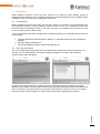
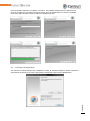
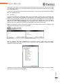
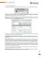
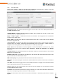
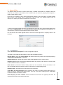
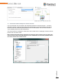
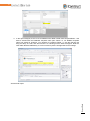
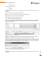
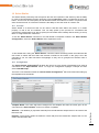
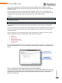
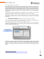
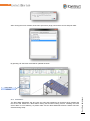
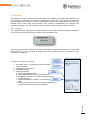
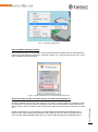
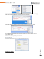
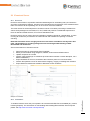
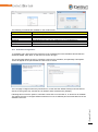
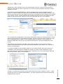
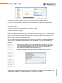
Running the Installer
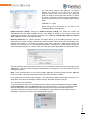
The user running initial setup should have local administrator rights. Right click the ‘setup.exe’ icon
and click ‘Run As Administrator’, the Welcome dialog will appear, click ‘Next’, and the feature
selection (below right) will appear.
Installation
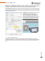
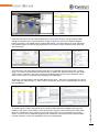
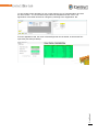
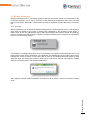
By default the installer detects the available versions of Navisworks and automatically ticks those
features to be installed. iConstruct Server Service and Revit Data Switchback Addins are features that
are not required for the general function of iConstruct and should be ticked only if the user is familiar
with them. Please consult chapters 21 & 22 for further information regarding these features.
11
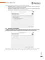
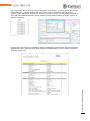
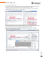
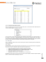
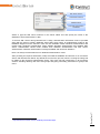
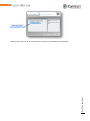
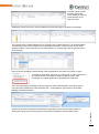
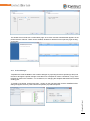
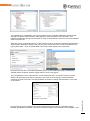
Once the Feature selection is complete, click ‘Next’. The installer will prompt for an optional server
name or IP address of an existing iConstruct server. This can be left blank if no server is available.
Click ‘Next’ again and then ‘Finish’ to start the installation process.
2.3
Licensing and Registration
Installation
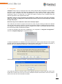
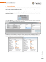
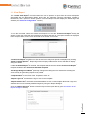
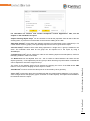
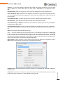
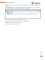
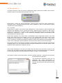
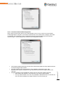
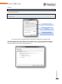
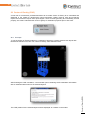
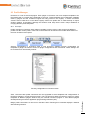
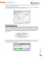
The iConstruct Toolset requires user registration in order to activate the product. When iConstruct is
executed for the first time, the user is prompted to activate the product via the dialog below.
12
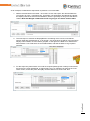
The iConstruct Toolset can operate in one of three activation methods:
2.3.1
Standalone License: A standalone licence will issue the user with a licence to operate the
Toolset on the PC to which the licence was requested.
Enterprise or Floating License: An enterprise or floating licence is network based, and
allows users to push and pull licences from a network pool.
Trial License: A standalone license with expiration time (usually 30 days).
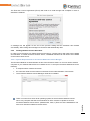
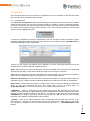
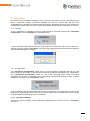
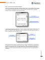
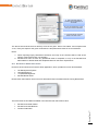
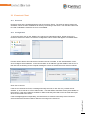
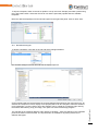
Standalone License Activation
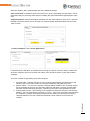
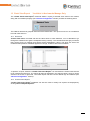
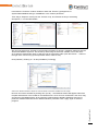
To activate a standalone copy of iConstruct select the ‘Directly via Internet’ option and press ‘Next’.
An iConstruct Activation Code will need to be input in the available text boxes and press ‘Next’:
Installation
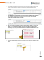
Please make sure that an active connection to the internet is available at this time. The activation
wizard contacts the online activation server and installs the iConstruct License on the machine.
13
The End User Licence Agreement (EULA) will need to be read through and accepted in order to
activate the software.
A message box will appear at the end of the process stating that the activation has finished
successfully. After closing this message box iConstruct will automatically start.
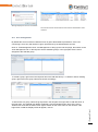
2.3.2
Floating Network License Activation
In order to use iConstruct in a floating license environment, a license server will need to be installed
and activated. To install iConstruct License Server, CodeMeter Runtime Kit will need to be installed
on the users license Server.
2.3.2.1 System Requirements for iConstruct Network License Manager
The iConstruct Network License Manager is part of the iConstruct setup, so you only need to select a
computer on your network that will act as a network server. To set up an iConstruct Network server as
following:
a computer with a network connection
the computer needs to have internet connectivity for the initial activation of the license
The iConstruct Network License Manager needs to be installed
There is no need for a server level operating system for the iConstruct Network License
server. Any computer that has recent Windows or OS X versions is capable to act as a
work as an iConstruct Network License server.
Installation
iConstruct Network License server. (Windows XP, Vista, 7) Even one of the workstations can
14
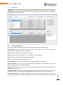
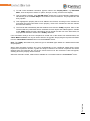
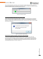
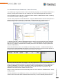
2.3.2.2 Activating License on the Server
Install iConstruct Network License Manager on the License Server
Run ‘iConstruct Network License Manager’ from start menu > iConstruct 2015 folder
Select ‘Activate License’ from File menu
Select the Directly via Internet (Stand-Alone License / Network License Server)
Input your Network License Activation Code
Follow the wizard to activate license
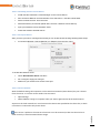
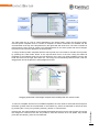
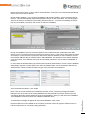
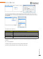
2.3.2.3 Set up the Server
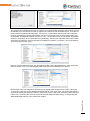
After you have your server running and licensed you can enable license sharing following these steps:
In iConstruct Network License Manager run ‘Settings’ from the ‘File’ menu:
To enable the Network server:
Check Run Network Server checkbox
Do not forget to Apply the changes
Make sure your clients have access to this port
2.3.2.4 Access Control
With the default settings all computers on the same local network (same subnet) may use a license
from the server. In case the access needs to be restricted:
Open Settings
Add IP address / range or computer name you want to grant access to the license server
Anyone on the local network can use a license unless entries are specified in the clients list, in which
case access is restricted to only those clients.
Installation
If the server is public on the Internet or licenses are to be restricted, make sure that this list is
filled correctly to avoid unwanted license usage.
15
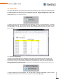
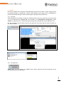
You may want to check who is using a license:
Open iConstruct Network License Manager on the license server computer
The main window will show you the list of currently connected clients:
Installation
Also you can get monthly reports of the license usage from ‘Reports’ menu:
16
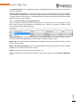
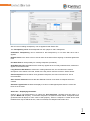
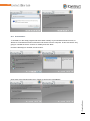
2.3.2.4.1
Client Side Settings
To activate iConstruct on a client using a network floating license select ‘iConstruct Network License
Server’ while activating the client for the first time:
Input the name or IP address of the license server that has been setup in the previous steps then
press connect.
After accepting the License Agreement the wizard connects to the server and activates iConstruct
using the network license server. iConstruct will start working after activation is complete.
2.3.3
Trial Activation
To activate iConstruct using a trial license contact an iConstruct dealer to obtain a trial license file.
This trial license file can only be activated on the machine once and will expire on an exact date and
time.
To activate the trial license select ‘Use Trial’ option in the activation wizard form and then choose the
location of the trial license file.
After the license file has been imported and the software license agreement has been accepted the
trial license will be imported and iConstruct will be activated.
Plug-Ins
iConstruct can run custom plug-ins developed using iConstruct APIs to increase its integration with
the users company’s needs and requirements. Please contact the distributor for further details.
Installation
2.4
17
3
Concept
There are a few concepts that iConstruct is based around, that once understood may benefit the end
user in getting the most out of iConstruct.
3.1
Read only Tabs
Navisworks models exported from Native CAD packages or loaded from the Native Files contain only
read-only data tabs. This is also true of datatools tabs – the data can be refreshed from the
datasource but the user cannot change the value of a property.
3.2
Hidden Tabs
Hidden tabs are also known as developer tabs – they are a method for writing data to a Navisworks
object (usually by way of a custom exporter) but without it cluttering the data tab window
unnecessarily. These tabs are still accessible through the iConstruct dialogs but not visible to the user
unless ‘Show internal properties’ is ticked in Global Options->Interface->Developer
3.3
Writeable Tabs
Writeable tabs are how iConstruct stores linked data within the Navisworks model. Generally the
process starts with Integrator, copying key properties from read-only tabs into a newly created,
writeable one that can be updated from several sources as well as manually appended. Currently
iConstruct only supports one writeable tab per object, and it is highly recommended they be named
the same across a project/company.
3.4
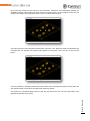
Groups vs. Items – Modelling Hierarchy
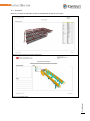
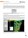
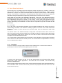
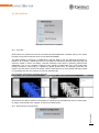
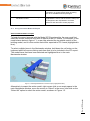
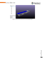
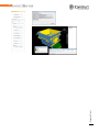
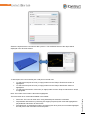
To get the most out of iConstruct in terms of speed of processing, it is recommended that items in
models be grouped to minimize the number of items that need to be involved during processing. For
example if the user are working on structural steel it is advised all the piece items are grouped by the
assembly, or in piping the components grouped by line number. This means that for the vast majority
of colour codes / datalinks there is much less processing required. Using selection resolution (First
Object for Groups, Geometry for Parts) allows the user to easily switch between the two. ReConstruct
can be of assistance in getting the model hierarchy organised correctly.
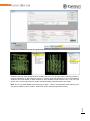
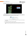
Concept
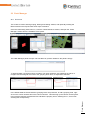
Example of a grouped structural frame. Selected with First object selection resolution (left) and Geometry (Right
18
4
First Look
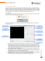
iConstruct embeds into Navisworks as an add-in module. To open the iConstruct application, select
the iConstruct icon from the iConstruct 2015 menu inside Autodesk Navisworks when using the
Standard Interface.
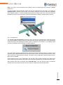
When the application opens, there is an option to pin the toolbar open and or dock into the side
control bars of Autodesk Navisworks. If the user closes the iConstruct window they will need to reopen it through the Tools menu. Note that when the iConstruct window is closed it will remember its
position and size the next time the application is launched.
4.1
Panel Lathe usert
The user interface sits within the Navisworks application with the user having the ability to dock or
float the iConstruct window like other Autodesk Navisworks Tools. On first run, iConstruct will open in
a docked position. To make the most of iConstruct’s intuitive button bar control, it is highly
recommended to use iConstruct as a floating window so that it can be moved around the main
workspace or onto a user’s dual screen.
iConstruct’s panel could be merged or docked with other Navisworks panels together to make it more
convenient for the user to manage the work place. iConstruct is designed so that existing Navisworks
users find it easier to become familiar with the interface while they are using it with other Navisworks
tools.
4.2
Standard Tools vs. Configuration-based templates
First Look
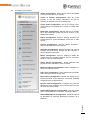
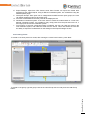
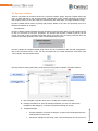
The iConstruct Menu organises the different toolset commands and settings to allow easier location
and identification by the user. Select these menu titles when accessing their relevant tool commands
or settings.
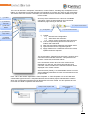
19
By default, at the beginning of the project/profile
setup, iConstruct will only begin with two menus.
These
include
‘Standard
Tools’
and
‘Configuration’. The Standard Tools Menu
contains a range of iConstruct tools that are
either
configured
through
‘General
Configuration’ or do not require any
configuration at all. This range of Commands
located under the Standard Tools Menu includes:
Append Data
Center of Gravity
Clash Manager (*Manage Only)
Create Clash View Report (*Manage
Only)
Create QA View
Create View Report
Find and Replace
iConstruct Properties
Info Bin
Laser Point Creator
Module Dimension
Preview
ReviewTrack™
Revit Client
Smart BCF Exchange
Smart DWFx Exporter
Smart IFC Exporter
These tools will always remain under this Menu
whether they require initial configuration or not.
Note: Menus that are made available to other users can be altered using iConstruct’s security
settings.
First Look
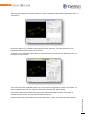
Once additional tools have been configured and
commands established, new menus will appear
for these relevant tools in which they will be
grouped under their associated functionality.
20
Under each menu there are commands that will perform the functions that have been setup through
the configuration settings. The commands listed are the results of templates created and saved under
the configuration menu.
To remove commands from the associated command menu, the user will need to delete this template
from the configuration menu.
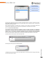
4.3
Security
iConstruct’s toolsets and configuration menus that are available to users can be customised and
saved to a user’s profile using iConstruct’s security option. This enables management to control and
monitor which toolsets are available to the users. To begin the customisation of a selected profile, the
approved user/administrator will need to click on the toolbar at the bottom of the main iConstruct
window and click the ‘Security Settings’ icon (see below). This will then prompt the user with a
dialogue box to set a password to protect the customisation that is about to be made.
Note: If the password needs to be changed, check the box change password. The old password will
need to be entered before the new one is accepted.
The security settings icon
Password dialog
Change Password dialog
After a password has been established, the iConstruct security option menu will appear.
Users/administrators, will then be able to select which tools and configuration settings are made
available to users of that profile.
First Look
Amendments can be made at any time by entering the established password when prompted, making
the necessary changes and clicking ‘OK'.
21
4.4
Profiles
A profile stores all the settings and configuration that has been done on all the toolsets and templates
inside of iConstruct, which then can be passed onto other users without having to replicate the same
configuration work. This allows management/consultants to establish customised profiles to suit
organisational, team, or project standards.
There are four options available for profile management:
- Save Profile: When selected will open a ‘Save As’ dialogue box allowing the user to create a new
profile or override/update existing. All configurations and amendments made will be saved or updated
to the new or existing profile.
Note: security passwords that are active will be saved to the profile.
- Load Profile: Allows the user to open previously saved profiles and import all the settings and
configurations associated to that profile. When a profile is loaded any existing profiles that are open
will close.
- Clear Profile: Closes the current profile and restores iConstruct to its default state. Clear profile
should be selected when the user wants to create a new user profile from scratch to avoid editing or
overriding existing profiles.
- Merge Profile: Allows templates from other profiles to be added to the current profile (see chapter
25)
4.5
Re-Launch iConstruct
First Look
Click the Re-Launch button to restart iConstruct (this will re-read the license information).
22
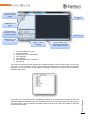
Configuring iConstruct
Audits Configuration: Define search sets to be audited
or set up to auto-filter by a property.
Center of Gravity Configuration: Sets the mass
property to use for density calculations, as well as
selecting an indicator icon for the COG result.
Colour Code Configuration: Set up for running colour
codes using Excel spreadsheets, Access, or ODBC data
sources.
DataLinker Configuration: Stamps data into a writable
tab in the Navisworks model from Excel, Access, or any
ODBC data sources.
Export Configuration: Used for defining templates for
exporting data to Access databases, Excel files or PDF
reports.
General Configuration: Sets the default properties /
other configurable items for iConstruct.
Integrator Configuration: Defines the data from various
property tabs that will be brought into the company or
project defined property tab.
Macro Configuration: Used for loading an XAML file
created with the workflow designer into the iConstruct
panel as a new command button.
Select Similar Configuration: Define attributes and
properties to be selected by common values.
Math Calculations Configuration: Define calculations to
perform on selected items.
Open File Configuration: Links Navisworks properties
with existing documents or PDF files.
ReConstruct Configuration: Choose the setting for reexporting models or part thereof to a new nwd, optimally
reorganising the model hierarchy.
Review Track Configuration: Configure the back-end
database to store viewpoint and comments data, as well
as nominate custom fields.
Smart DWFx Exporter Configuration: Sets the model
name and the data tab to use when exporting to DWFx.
Smart DWG Exporter Configuration: Saves the options
as templates for exporting Navisworks geometry as a
DWG file.
First Look
4.6
23
4.7
General Configuration
The ‘General Configuration’ interacts with multiple toolsets and some of the default display settings.
After the user opens and begins to edit the ‘General Configuration’, like with most of the other
configuration options in iConstruct, the user should select a sample of objects in the model that
represents the data/property names the user wishes to look for.
Selecting the entire model will provide access to all available data tabs and properties, but will take a
lot longer than picking a few ‘Typical’ items. Once a few items have been selected (or the entire
model if desired), click on the ‘Get NW Properties’ button.
This will then provide the user with some general configuration options, which may require an attribute
and property for each option. These options include:
Default Data Tab: The default data tab to write data to when running commands through iConstruct.
Please note the default data tab must be a writable tab. Only an Attribute value is required and no
Property value.
Clash Report Property: The custom property the user wishes to have for each element in
iConstruct’s view report. This information could be internal data of the object or any external data that
has been brought into the model through DataLink (see Clash Report). Note this property is not
required to be set and will be removed in future releases. It is included just for compatibility purposes.
Info Bin Property: The property name used for Info Bin folders where drawings and other files are
stored related to selected objects in the model. If an object is selected and the Info Bin icon pressed,
it will search for the Info Bin folder associated with this defined property. If no Info Bin folder exists,
iConstruct will prompt the user to create one.
The other general configuration options, that are not associated with the models attributes and
properties, are the report settings. This includes:
First Look
Default Report Logo: allows users to import or select a company or project logo to display on
iConstruct’s report output as a default unless specified on other templates.
24
Default Report Address: allows users to enter a company address or custom text field to be
displayed at the header of iConstruct’s report output as a default unless specified on other templates.
Default iConstruct Font and Size: allows the user to choose the default font and size to be used in
the iConstruct interface and dialogue boxes.
iConstruct Scale Mode: will determine whether the dialogue boxes and the text displayed are
rescaled depending on the resolution settings. This option should be used if the users are having
issues with the visibility of the dialogue boxes.
First Look
Note: By default this setting should be set to ‘font’, and set to ‘off’ if the user is having issues viewing
the interface.
25
5
Integrator
‘Integrator’ allows users to create the their own custom data tab within Navisworks and takes data
from one or more read-only data tabs and combines them into a custom data tab. This is used in
situations where companies may want standardisation of what data they want displayed when
selecting an object in a model and or to reduce the hassle of having to look in different tabs and
different properties for the required information.
Integrator is key to using iConstruct successfully as it takes the user from using read-only
data in the models to being able to add data from several sources as the models are shared
through the project.
Note that only one user data tab is able to be created per object.
This could also be used at a project level where the user may be receiving models from different
sources and need to set up a project or company specification based on standard required properties.
The Integrator command provides the option to configure and create a user defined data tab for both
Items and Groups within the Navisworks Model.
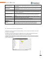
To map the standards that have been established in the templates in ‘Integrator Configuration’,
select the ‘Integrator Mappings’ to expand the menu.
To map the properties to a standard, select the relevant items and/or groups that are to be mapped
and then select the Integrator Mappings command that was created when the template was saved. If
the user has a pre-existing User Data Tabs, a prompt like this will appear.
The model will need to be saved in order for the mapped properties to remain within the model. If the
model was not saved, the user can re-run the command at another time and then save the model in
order to save the new User Data tab information.
Integrator
If the standards are mapped successfully, users will receive a similar success message;
26
5.1
Configuration
To begin the configuration the user will need to select a sample from the model, and then click the
‘Integrator’ icon to open the Configuration window. Depending on whether the user is working with
the Integrator on Items or Groups, they will need to make sure the sample that they have selected
suits the level they are working on.
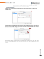
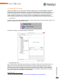
5.1.1
Configuration Window
There are a number of items on this configuration window that will make Integrator work;
Get NW Props: collects the data from the selected sample Item or Group data to be used in
Integrator when setting up the custom data tabs.
Load: Load a saved Integrator Configuration template.
Save: Save the current configuration to a new template or update existing.
Delete: Delete a saved Integrator Configuration template.
Close: Closes the Integrator Configuration menu.
Template Name: The name to be assigned to or already assigned to the template.
Saved Templates: This is a list of the saved Integrator templates. When selected, these can be
opened for editing and then resaved or deleted.
Data Tab Name: Will be the display name of the customised data tab inside of Navisworks when the
‘Integrator’ command is run.
Show Internal Names: If checked, it will display a read only column in the configuration grid of the
internal property names of items selected within the model. This can be used if the user has renamed
Integrator
Use first attributes for all: If all the properties are from one tab the user can check the ‘Use first
attribute for all’ tick box, which will make the attribute field the same as the first for the whole list.
27
the ‘Standard Name’ in the configuration grid to a standard terminology, and still need to check what
property it relates too.
Enable Subgroup Searching: looks at items within the group for properties that cannot be mapped
on the group. For example if the user had no group data tab, but the items inside the group contained
a property relevant to the group (i.e. Assembly Number), this option would find the first matching field
within the group and use it instead.
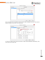
5.1.2
The Item and Group Configuration Grid
After the sample properties have been retrieved from the model, the user can now begin to set up
their custom user tab using Integrator’s configuration grid. There are a number of columns in this
section which will assist with the process;
New Property Name: The name that is given to the property inside of the custom user tab. This can
be used to create a standardisation in terminologies for properties within models.
Model Tab: The internal Navisworks attribute that Integrator will be collecting the data from to include
on the custom user tab.
Model Tab Property (Attribute): The internal Navisworks property that Integrator will be collecting
the data from to include on the custom user tab.
Option: The optional conversion to use (see section 5.2)
Integrator
Once a template has been saved an integrator command will appear in the ‘Integrator Mappings’
menu.
28
5.2
Integrator Options
There are a few conversions that can be used with Integrator to perform
extra functions on the data as it is being transferred and therefore maximise
efficiency as well as sanitise data.
In prior releases these conversions had to be typed in, but from 2014
onwards they are now available in an easy-to-use drop down list.
Optional keywords
Convert To Decimal: Attempts to convert the property to a decimal number, stripping away any text
from the property value. If the property cannot be converted to a number then the default ‘0’ is used.
Convert To Integer: As above but converts to a whole number instead of a decimal
Convert To Date: Attempts to convert the value to a date format. Note that Navisworks does not
currently support date formatting or time zone information so use this carefully.
Format As Text: Takes the existing value and converts it to text
Sum Group Property: Use with ‘Enable subgroup searching’ to add the item field as a total for the
group node.
Perform Calculation: Displays the calculations stored in the profile for users to select to run when
processing the property. Good for converting metric to imperial measurements.
Convert From Revit: Converts from the native Revit data type (volume, length etc) to a decimal
number. Also removes any extraneous text from text fields.
Use Parent Property: When processing an item field, first looks in the parent node for the same field
and uses that instead, like ‘Enable Subgroup Searching’ (see 5.3) in reverse except the parent
property takes precedence. Useful when processing Revit models so all unique identifiers are at the
same hierarchical level.
Use Parent Revit Property: Same as ‘Use Parent Property’ except ‘Convert From Revit’ is applied at
the same time.
5.3
Subsearch – creates group tabs
Integrator
By ticking the ‘Enable Subgroup Searching’ checkbox the routine will, in the case that data is not
found on the group tab, pick the property data from the first object in the group. This is useful if a
group tab has not been created by the native exporter and the user wishes to add an assembly mark,
for instance. As mentioned above the SUM keyword can be used to sum a numeric property from all
items in the group and place on the group tab.
29
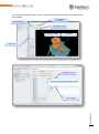
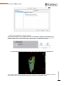
5.4
Example
Integrator
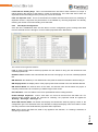
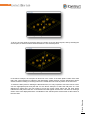
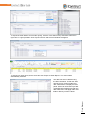
Below is an example Integrator template showing the data sanitation options ‘Convert To Integer’ and
‘Convert To Double’ in the ‘Item Data Mapping’ panel, and an example of creating a new Group Data
tab by ticking ‘Enable subgroup searching’ and using the ‘Sum Group Property’ option to create an
Assembly Weight (kg): field.
30
6
DataLink
The Datalink command provides users an easy to use interface with tools that allow bringing any
external company and project data into a fully co-ordinated and collaborated model. With compatibility
to XLS, MDB or ODBC Data Sources, companies can now further extend the amount of information
included in a BIM Model inside of Autodesk Navisworks.
The external information and properties are then displayed in a user defined properties tab, which sits
within the Navisworks interface. All fields within this properties tab are rewritable which provides the
option to re-save or export back to the original data source via Excel or preferably MDB.
Important Note: If iConstruct is running on a 64 bit operating system, the 64 bit Microsoft ODBC
drivers need to be installed. If any Office 32 bit components are installed on the machine it will need
to be completely uninstalled and upgraded to 64 bit Office.
6.1
Concept
Data Link is a powerful tool that provides the ability to bring in related information from external data
sources and be displayed within the Navisworks model. Once a link is established the data will save
itself to a rewritable tab (see Integrator) that the user has set up. The Data Link configuration is best
used by people with some knowledge of the database system, once set up however; it is simply a
mouse click on the command to import the data into Navisworks.
Select the ‘DataLinks’ tab to expand the menu to establish a connection through the commands
created in the ‘DataLink Configuration’.
To establish a link and import the data from the external data source, select the associated items
and/or groups that the data needs to be applied to and select the relevant command. If the data has
been successfully applied to the defined properties tab, the user will receive the following confirmation
message:
DataLink
Note: The model will need to be saved for the DataLink data brought in from the external source to
remain within the model. Updated data can be brought in by re-running the command on relevant
objects.
31
6.2
Configuration
To begin the Data Link configuration users will need to select a sample from the model, and then
open the Data Link Configuration window.
With the configuration window open and sample selected, users will need to select ‘Get NW Props’ to
identify the attributes and properties that the external data is going to be written to. The user will need
to also identify the external data source that they wish to connect to, which can be chosen under the
data source ‘File Name’.
DataLink
Data Link supports links to Excel, MS Access and ODBC, with the method to configure Data Link for
each being the same. For the link to work the user must have a unique property that exists in the
Navisworks model that is able to match up with a similar property in the external data source in order
to bring its associated data across into the right item or group.
32
6.2.1
The Link Setup
There are a number of areas on the Data Link Configuration that will help in setting up the link
between the Navisworks model and the external data source;
Data Source Type: The external data source type to connect with. This can be Excel, MS Access or
an ODBC data source type.
Template Name: The name that the DataLink template will be saved with and will be used in the
command under the ‘DataLinks’ menu.
Apply to Object Types: To determine whether the information will be applied to the Navisworks
model’s groups and/or items.
Select Table: The table from within the external data source that is to be drawn into the defined
Navisworks properties tab.
Target Attribute: The attribute that Data Link will append the linked data to. Note that this tab doesn’t
need to exist in the model – DataLinker will automatically create a new tab in a similar fashion to
Integrator. The ‘Linking Attribute’ must already exist on a read-only tab though.
Exists Action: Tells the DataLink command whether to overwrite the data or not when it is run. There
are three options that can be selected: ‘Don’t Overwrite’, ‘Prompt for Overwrite’, and ‘Always
Overwrite’.
Linking Attribute: The attribute that Data Link will search within for the same value as in the external
data source to create the link.
Database Link Field: The field within the table from the external data source that users wish to use
as part of the link to the Navisworks model.
NW Link Property: The property field that the external data value will write too.
File Name: The name and option to select the external data source (Excel, MS Access or ODBC) in
the link.
Filter Data: allows users to apply rules to control what information is brought in from the external data
source with the Data Link tool. This is broken up by;
Field: the field from the external data source that the user is bringing into the Navisworks model’s
properties that they wish to filter.
Value: the value that the user wishes to use as the benchmark or determining value for the condition
applied.
DataLink
Condition: the rule that the user wishes to apply to the filter, to control which information will be used.
This can be an equal to, greater or less than, or like condition.
33
Link Fields are Primary Keys: This is recommended if the link field or fields combined, is unique. It
makes applying the data up to 60x faster in certain circumstances. The routine will warn if there are
duplicates for the link field(s) and the primary key cannot be created.
Filter out duplicate rows: This is recommended for smaller data sets where there is a possibility of
duplicate records. It improves the performance of the Datalink by removing duplicates and thereby
reducing the number of records needing to be searched.
6.2.2
Data Import Configuration
Once the link is established users are then able to use the configuration grid to manage what data
from the external source is brought in to their created properties tab in Navisworks.
The columns in this grid are used for:
Link: is used to select which external properties the user wishes to bring into the Navisworks user
created properties tab.
Database Field: identifies the external field that the user is bringing in to the user created properties
tab.
NW Attribute: the attribute (or user defined tab name) that the external information will be writing to.
NW Display Name: the display name of the property that will be created in the user defined data tab.
NW Internal Name: the internal name of the value, this internal name should match the project or
company internal name for consistency of data throughout the model.
Excel Headers: look for headers in the Excel spreadsheet before reading the data.
Enable Multiple Properties: used if more than one record is returned from the Data Link. For
example when multiple records are returned for 'Drawing', the properties would be applied as
'Drawing:', 'Drawing2:', 'Drawing3:' etc.
Show NW Internal Name: will enable and display the Navisworks internal property names in the
configuration grid. This will assist if the user decides to change the display name and needs to make
sure they know the internal Navisworks properties that it represents.
DataLink
Note: when running the Data Link, data is only applied to the selection, or if nothing is selected, to
everything in the model.
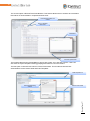
34
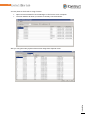
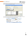
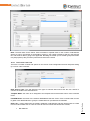
In the case that there may be several columns or fields that the user wishes to apply as a single
property, ensure that the internal and display name for the required fields are the same for all. Only
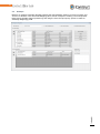
the first matched property will be applied. For example:
On row 251, GW is the first matched property for the Class name and will be applied. On row 252,
LW is the first matched property while on row 253, PW will be applied.
DataLink
Excel Spreadsheet
35
7
Info Bin
Info Bin links Navisworks model objects with a folder located in the model’s directory. If the directory
does not exist, the user is prompted with the option to create one. This provides construction
professionals with a streamlined way of collating and organising relevant information against items
within a model. This information could be anything from construction documentation, invoices,
installation procedure etc. and can be added to at any stage during the construction or design
process. Once information bins have been assigned, these can quickly be recovered so users can
retrieve the relevant data located within these folders.
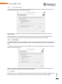
7.1
Configuration
Info Bin configuration is available from the ‘General Configuration’ in configuration menu. The
property name used for Info Bin folders where drawings and other files are stored related to selected
objects in the model could be changed and configured from this panel.
By default the info bin folder is local to the selected item’s model folder. To choose a new root folder,
hold down the left shift key when clicking InfoBin to be prompted for a new location.
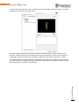
7.2
Example of use
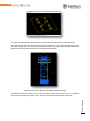
Info Bin
Below is an example of linking miscellaneous documents to the Assembly Mark of an object in a
model.
36
8
Append Data
The Append Data Command is used to add, modify, or delete custom data to a selection within the
model, to the Attribute name defined. This command can be useful for grouping items together or
adding custom data on the fly.
From 2014 is the ability to save custom append data buttons to the main panel, for quickly adding
data to items in the model. This is useful when using a model on a windows tablet on-site for
example, for capturing the status of steelwork or other items.
To perform the Append Data Command, first highlight the items that are to have the data applied, and
then click the ‘Append Data’ icon. The append property dialog will be displayed in its default form. To
add a property, enter the Property Name and the Property Value.
For use with the new custom append buttons, the user can also right-click in ‘Property Value’ to set
the dates
8.1
Configuration
Select ‘Show Advanced Options’ to show configuration options.
The fields on this advanced tab provide the user with the following options:
Internal Name: shows the ‘Internal Name’ that will be used for the property (an important property if
‘Create Tab if Non-Existent’ is checked).
Apply Property To: whether the property value will be applied to items, groups or both.
Property Type: the data type that will be displayed within the property. This can be set to text, whole
number, decimal number, or date/time.
Exists Action: determines whether existing values are not overwritten, always overwritten, or the
user is prompted (which provides the option to roll-back any changes being made).
Create New Tab if Non-Existent: When checked it will create a new tab to append the data to if it
does not exist on certain groups and/or items. This may occur when working from a collaborated
model with multiple consultants’ models.
Delete Property if Value is Blank: When checked this will remove the property field from the
selected items if the value has been left blank.
Append Data
Property Value: add value here or right click for pre-set options
37
Apply Colour / Transparency Overrides: If checked, it will apply the selected colour and level of
transparency to selected objects. This might be useful for grouping. Sliding the transparency to the
left will make it opaque while sliding to the right will make the selected objects less visible.
Save View Point as: When ticked, uses the name in the text box to save the current viewpoint after
applying data. Note that when this is ticked the user will be prompted for a comment also, just click ok
to dismiss if no comment is required. This is handy in the instance that an item has failed some status
and a note needs to be made.
Templates: Enter a template name, and click the
icon button to select a custom icon for the
template. When saved the append data
commands will appear in a new ‘Append Data’
tab. This can the be dragged off the panel in
Tablet UI mode (see later chapter) and used on a
windows tablet pc for quickly checking off items.
8.2
Use as a Workpacking Tool
Append Data
The Append data tool can be used to assist in workpacking and attaching items to Timeliner by
changing the ‘Exists Action’ to ‘Auto-increment’ (as shown). This in combination with the Audit module
can quickly generate selection sets based on Activity / Workpack IDs and supports multiple IDs per
item.
38
9
Find and Replace
Find and Replace functionality will allow users to edit and update model data when and where
required. These tools will help improve quality and reliability of model data as changes can be made
easily to keep all project information up to date.
The primary use of this tool is to fix up the models temporarily so work related to the model can carry
on while the native cad data is fixed up (i.e. spelling mistakes, incorrect codes etc.). It is not intended
to be the final solution and any fixes done to a model should be considered short-term until the data
source can be fixed up.
Select ‘Get NW Props’ to get the properties of an object selected in the model. Specify the attributes,
properties, values to find, and values to be replaced with.
Find and Replace
Use wildcards like the hash key (#) to denote a numeric value that won’t change. Use an asterisk (*)
to find all values for that property to be replaced with a specific value. Press the Replace button and
see the changes in the iConstruct Data properties tab.
39
9.1
Options
‘Find and Replace’ offers various combinations of property search. Users can set these combinations
using onscreen configuration options:
Use Wildcards: Allows use of asterisks (*) to find any value for that property to be replaced. Also
allows use of hash keys (#) to allow numeric values to be left unchanged.
Replace Property Name Only: The name and not the value of the property is replaced.
Find and Replace
Show Datatype: After checking Show Datatype, select in the Datatype Column, text, whole number,
decimal number, or datetime. Pressing the Replace button will convert this from the current datatype
to the one selected.
40
10 Introduction to the Report Designer
The iConstruct Report Designer allows the user to create their own custom report templates to
provide advanced and visually attractive report outputs. This will help the user with creating more
meaningful and presentable reports to help support them during the decision making process on
projects. The user can design their custom reports using Report Designer for exporting data (see
‘Export Data’ section), design report in View Report command (see ‘View Report’ section), or to
customize a Clash View Report (see ‘Clash View Report’ section).
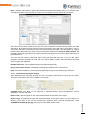
10.1 Report Designer Interface
Report Designer form consists of several parts:
Main Menu: Contains a set of items and sub items, which enable users to perform common
actions over the report currently shown in the Design Panel. In general, it duplicates all the
toolbar buttons available on the Main, Formatting and Layout toolbars. And, the Window
menu allows disabling the tabbed multi-document interface, and tiling the Design Panel
windows vertically or horizontally.
Toolbox: Allows users to add controls to a report, by dragging and dropping their icons onto a
report's area.
Report Explorer Panel: Represents the visual tree of a report. It shows a report's structure in
a tree form, and makes navigation through the report easy.
Field List Panel: Shows the structure of a report's data source, and is used to bind report
controls to data.
Property Grid Panel: Used to access and modify properties of a report and all its elements
(bands and controls).
Design Panel: This is the Designer's main element, as it represents a surface where a report
is being edited and previewed. The Design Panel has four tabs; (Designer, Preview, HTML
View and Scripts), for report editing, previewing, and maintaining its scripts.
Component Tray: Shows components (non-visual report helpers) related to report data
binding. The user can click them to display and edit their settings using the Property Grid.
Group and Sort Panel: Allows the user to quickly perform grouping and sorting operations
throughout a report, and visually represents the report's grouping structure.
Toolbars: Includes Main Toolbar, Formatting Toolbar, Layout Toolbar, and Zoom Toolbar;
each represent all functionalities from main menu available in the fast and convenient way for
designing the users report.
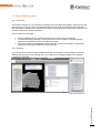
10.2 Basic Grouped Report – Example Walkthrough
The End User Report designer allows for grouping, sorting and using charts to be able to display
model data concisely and accurately. As an example we will look at creating a basic multi-level
grouped report. See ‘Export Data’ section for further information on creating a Report Template for
use with the report designer.
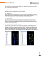
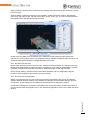
Introduction to the Report Designer
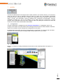
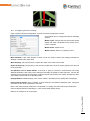
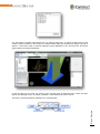
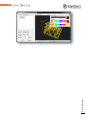
In the example picture (below, right) of the model, an item of furniture is selected along with the
relevant data tab showing the ‘Component Item’ and the ‘Level Location’. These will be our main
properties to group by to produce a report listing quantities of Furniture for each Level Location (see
below, left).
41
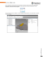
Sample item selected showing data to report by
The finished report
Once the user has set up the report template (see ‘Export Data’ section), a large sample of data
should be selected to give a good indication of report output, then click on the ‘Report Designer’
button (see below). The default report prototype will appear. To set the initial logo (if not selected in
the Template editor) click the top left (Image) box, then click the ‘Image’ Property under ‘Data’ and
select an image.
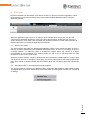
In its initial form, the report will just output each item as a separate row (see below, left). To add a
group, or to sort by a specific field the ‘Add a Group’ or ‘Add a Sort’ buttons need to be used. When
‘Add a Group’ is clicked, a sub-menu showing the available fields to Group By is displayed, in this
case ‘Level Location’ is clicked and the Grouping level is displayed.
To create a group header, drag and drop the relevant header field from detailband into the group
header (in this case ‘Level Location’). This will group the report by Level Location (see below right),
which is acceptable for some reports but in this case the report is to sum quantities by Furniture
Group, so in this case an additional grouping level is added for ‘Component Group’ (below middle)
and both fields are moved from ‘detailband’ to the new groupheader.
Introduction to the Report Designer
At this time a ‘GroupHeader1’ band is also added to the report – this can be switched off/on or add a
footer using the ‘Show Header’ or ‘Show Footer’ checkboxes. Note that the original fields are still all in
the ‘detailBand1’.
42
Also ‘Component Group’ is copied for us to change the ‘Sum’ field for. To sum by group, first click the
field box then the > box that appears above it (A). Then click the Summary button (B) and the
Summary Editor will appear. Change the ‘Summary Function’ to ‘Count’ (C) as the intent is number of
(if for total mass SUM would be the chosen function). Finally set the summary per page, report or in
this case Group (D).
Introduction to the Report Designer
And the final report, after minor formatting change to highlight the groups (select field and change the
‘Background Color’). Note this report picks up items not categorized by a Level Location, hence the
empty first header row.
43
11 View Report
The ‘Create View Report’ command allow the user to produce a report from the saved viewpoints
associated with the Navisworks Model, along with any attached comment information created in
Navisworks, and a space for written remarks. The View Report will also display the default logo and
address (see ‘General Configuration’ section).
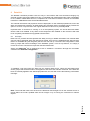
To run the command, select the Create View Report icon and the ‘Create View Report’ dialog will
appear. Check the views that are required for the report and click ok. The report will then be displayed
in the sample viewer, where it can be saved out as a PDF or Excel file.
‘Create View Report’ templates can also be used to modify how reports are displayed by clicking
‘Show Template Options’. Report logos and company address files can be selected for display
along the header.
If ‘Use as Default Report’ is checked, this template will become the default ‘Create View Report’
template instead of the iConstruct Standard Template.
‘Set Image Background White’ optionally changes the background to white before creating the
views, handy for generating reports to be printed.
‘Template Name’ is the name of the Template to save as.
‘Report Logo File’ nominates the logo to use on this template
‘Report Address File’ nominates the default address to use on this template. Note both Logo and
Address files can be manually added/changed by using the ‘Report Designer’
View Report
Click the ‘Report Designer’ button to edit the layout of the report directly (see ‘Introduction to the
Report Designer’ section).
44
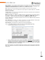
When the ‘Options’ tab is selected there are some additional settings:
‘Run Colourcode’ nominates a saved colourcode to run prior to generating the view report – this is
especially handy for producing status reports. Enabling this option also adds a legend panel to each
view.
‘Import Properties’ reads all associated properties from the visible objects of each view – note that
the data is for all the objects across all views. For producing view-dependant tables use the ‘Insert
Table’ function.
‘Locator Viewpoints’ and ‘Locator Appearance’
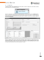
If ‘Generate Plan & Elevation’ is checked before running the reports, iConstruct will try to determine
where the viewpoint camera is focused, and draw a circle around the area in a plan and elevation
viewpoint.
There are 3 modes for generating the locator viewpoint:
View Report
1. Auto-Generate – Unhides everything in the model and automatically generates a plan and
elevation view of the entire model. On very large models this may take some time.
2. Specific Views – The user can nominate a standard plan & elevation view. For large models
this is preferable as the user can hide bolts, plates etc and leave only large concrete slabs
and other relevant identifying geometry, speeding up the locator view generation process.
3. Property-based views – This is handy if, for example the viewpoints are part of a multi-story
building – the user could assign a property i.e. Floor 1, Floor 2 etc to the items and then when
the viewpoint is created, the property is read from the visible items and the first matching
viewpoint selected. This way a sectioned viewpoint can be made per-level to improve
visibility.
45
Sample report view – note the locator circle
11.1 Navisworks Saved Viewpoint & Folder structure
It is recommended users are familiar with Autodesk Navisworks viewpoint structure – for further
information please consult the help system within Navisworks. It is recommended for best use of
iConstruct that ‘Save Hide/Required Attributes’ and ‘Override Material’ are both set as default in
Tools->Global Options from within Navisworks.
This ensures that new viewpoints created from colour-coded views or displaying a selection subset
preserve the view when saved.
View Report
Note, however that when using viewpoints for running a colour code as part of a report, the
user will need to untick Override Material for the views/folder to ensure the updated colours
are used instead of the saved colours.
46
11.2 iConstruct Table Control
The iConstruct Table control gives the ability to add custom tables based on the visible model data to
the view report. The first pre-requisite for this is that ’Import Properties’ is enabled.
To create a table definition, first open or create a report in the report designer, then on the toolbar
click and drag the ‘iConstruct Table’ control onto the page.
Then to show the table editor, click the > symbol on the top right of the control (circled above),
followed by clicking on the ‘iConstruct TableControlEditor’ link. Once the ‘Table Wizard’ appears, drag
and drop fields from the Field List->Report Data->ObjectProperties into the table.
View Report
Drag all the required fields into the table before changing other settings (i.e. don’t tick
‘GroupBy’ until all the fields are in place).
47
As an example, to illustrate the steps taken to produce a cost code table:
1. Add the relevant fields to the table – since this is a cost code report, the relevant fields are
‘Cost Code’ (to group + summarize by), Unit Value, Unit of Measure and Weight. By default
the display name is the same as the fieldname, which is generally too long once the table is
created. Note that Weight is added last as we are going to use that to total the table.
2. The next step is to rename the DisplayName to something more concise, note that the
numeric fields are prefixed with an ‘s’ (for single) – this is because we will be using the Group
Display name instead, once the field is grouped. To the right is the table as-is. Note that for
items without a cost code there are some blank fields, and that the data is not grouped or
summed.
View Report
3. For this report only items with a cost code are required (although this is handy to show there
are items in the view unassigned, so reports may vary). So ‘Required’ is ticked in the ‘Cost
Code’ column, and at this point ‘GroupBy’ can be ticked next to ‘Cost Code’ also.
48
4. The next part is to rename the grouped column names, and to add a total to the table. To do
this tick the ‘Show Advanced’ checkbox, and extend the panel to show all the columns.
5. The only changes that need to be made are for the ‘TotalInGroupDisplay’ names to change
for the table, and to tick ‘TotalInTable’ on the total field and give it a display name also (in this
case Weight is a consistent unit so that will be used for the summary). Note the Total
column must be the last column in the table.
6. Now when the report is previewed, the table has the right data but appears too small to read
clearly. To fix this, switch back to ‘Design’ mode in the report editor and stretch the table
control across. The table control automatically adjusts the height of the table according to the
width set by the report designer.
View Report
7. Previewing the report for the final time shows the table now has the correct data and is clearly
legible.
49
To save a table control template, for use in other reports, type a ‘Template Name’ and click
the ‘Save’ button – to use in another report select the template and click ‘Load’. The
appearance of the table can also be changed by switching to the ‘Appearance’ tab.
View Report
From the appearance tab, the colour of the background can be altered, as well as the font
style used (see example below).
50
11.3 Examples
Below are a couple of examples of what is possible with the export view report.
BOM View Report showing dynamically created table
View Report
Colour Coded Status Report
51
12 Clash View Report
*Available in Navisworks Manage Only
The ‘Create Clash View Report’ command allows a report of selected clash views to be created,
along with a nominated property (see ‘General Configuration’ section) for both the clashing items.
The Clashes will also be grouped under their associated batch. The report can be run on a model that
has had clash tests run.
12.1 Overview
‘Create Clash View’ command will use the clash saved in clash detective, so it is advisable to go
through the clashes first to get the viewpoints looking correctly. The command will also grey out all the
items except for the 2 clashing items which will be highlighted in yellow. This does not work if the
model has had presenter materials applied to it though, as these cannot be overridden.
To produce a report, select the ‘Create Clash View Report’ icon and select the Clash Views that are
to be included and select ok. The report will then be displayed in the sample viewer, where it can be
saved out as a PDF or Excel file. The Clash Report will also use the default logo and address (see
‘General Configuration’ section).
12.2 Create Clash Report
‘Create Clash View Report’ templates can also be used to modify how reports are displayed by
clicking ‘Show Template Options’.
52
For information on ‘Custom’ and ‘Locator Viewpoints’/’Locator Appearance’ tabs, see the
chapter on the standard view report.
‘Import Clashing Object Props’ can be checked to read all the properties from all tabs of the two
clashing items, to present more information to the end user relating to the clash.
‘Skip View Creation’ is used when the clashing properties are required but not the viewpoints (i.e. for
a clash status summary graph). This significantly improves the time to generate the report.
‘View Per Group’ instead of each clash being reported on a single view, a group is treated as one
clash. The individual clash data for the group can be reported on in the report by using a
‘DetailReport’
‘Transparency Level’ can be checked to make all non-clashing objects semi-transparent, useful for
identifying clashes in hard to see areas.
The Read Level can be adjusted from 0-9 – this is useful as Clash Detective will return the two
objects’ geometry – if the objects are part of a group or block and the group information is needed this
can be adjusted to read from a higher level up.
‘Force Text’ is used when there are inconsistencies with the model property datatype (i.e. a property
value changes from a date property type to a number on certain objects). This option forces all data to
be treated as text in the report.
Clash View Report
‘Auto-Reveal’ is used to ensure the clash point is not obscured by other geometry.
*Available in Navisworks Manage Only
The colour of the clashing object can be selected by changing the colour of the CR1 and/or CR2
buttons. This is useful for singling out each object in a clash.
53
13 Property Panel
The custom iConstruct Property Panel will help reduce confusion whilst supporting project standards
as users can use this to create a simplified display of object properties. It also will reduce the amount
of navigation required to find project related data, and with read-only functionality, will also help
protect the integrity of information behind the model from unauthorised editing.
Property Panel
The property panel will display property and value data from an item selected in the drawing as
defined by the ‘Default Data Tab’ attribute in ‘General Configuration’ (see ‘General Configuration’
section). The panel can be docked or floated freely.
54
14 Export Data
The export data feature of iConstruct allows users to produce their own reports from Navisworks data
in various formats, from Excel sheets to a well formed report. To get access to the Export Data
Command’s that have been set up and established using the ‘Export Configuration’, select the
‘Export Data’ Menu to expand the menu.
To produce a report, select the items within the model that a report is to be provided on, and select
the appropriate command. For Excel, MS Access and Clipboard, it will either write to the file or open
in the application. For the report option a preview will be displayed before having the options to save
to PDF or Excel.
14.1 Export Configuration
To begin configuring an export template, the user will need to choose sample data in which to draw
the property fields that will be included in the report and select ‘Get NW Props’.
Export Data
The Export Configuration allows for selecting report types to be generated and what content to be
included based on selected elements within the Autodesk Navisworks model. Once a template has
been saved, an export command will be added to its associated menu. After this has been added to
the menu, the user can produce on-the-fly reports from selecting items within the model and running
the appropriate export data command.
55
Note: Attention will need to be paid to the selection resolution that is being used, e.g. if the user picks
a sample item and it is the sub-part of a group, the group data property names will not appear.
Once the data has been refreshed, the user will need to determine whether Group and/or Item data
will need to be included in these reports. Click the drop down menu and select ‘Group Data’, ‘Item’ or
‘Link Group with Item’, depending on if the user wants Group information, Item information or a report
showing items that make up a group. Once this has been selected the ‘Fields to Add to Export’ will
populate. Select the properties to be exported and they will appear in the content grid at the bottom of
the dialogue box.
The user will then need to determine which report file type that they wish to use for the export
template. iConstruct provides the user with four export options: Report, Microsoft Excel, Microsoft
Access, and to the clipboard.
Disable Recursion: When disabled will process selected paths only
Ignore Items within inserts: Disregards matching data if below insert or block level.
Note: The columns within the content grid will adjust depending on the reporting type selected.
14.1.1 Customising the Report Display
After determining the reporting file type the user can begin customising the report and its output.
There are a few options that can be edited in this section:
Template Type: The data can be exported to standard reports, Excel spreadsheets, Access
databases, or to the clipboard.
Report Title: This will appear on the report output header as the name of the report.
Export Data
Report Logo: This defines the logo that will be presented on the report output. If a report logo is not
defined in this field it will use the default logo assigned within General Configuration. Enter
‘%MODEL%\CompanyLogo.jpg’ if the logo is in the ‘nwd’ model’s folder.
56
Report Address: This will display a defined address on the header of the report output. The user will
need to load in a text file (.txt) with the address as a paragraph for this to be displayed. Enter
‘%MODEL%\CompanyAddress.txt’ if the address is in the ‘nwd’ model’s folder.
Note: Report Title, Logo and Address will only be displayed on report and ‘.xls’ report types.
Report Page Size: The user can determine the report paper size (A3 or A4) and or orientation
(Portrait or Landscape).
Template Name: Is the name that the template will be saved under, and the title of the command that
will appear under its associated menu.
MDB File and Table: The ‘.mdb’ file (if ‘.mdb’ report type is selected) that the user wishes to write to
as a report is specified by either typing directly into the ‘MDB File’ / ‘MDB Table’ textboxes, or
selecting the ‘...’ button to the right, which will bring up the ‘MDB Access Details’ dialog box.
Prompt if MDB Exists: If checked will prompt the user if the Access ‘.mdb’ file already exists and
should be overwritten.
Note: ‘MDB Export’ is presently not capable of appending to an existing database. Selected data
should be uploaded from the ‘mdb’ to a central database if this is required.
Report Designer: Click this button to modify how the report will be displayed.
14.1.2 Linking Export Reports to external live data at runtime (Report type only)
1. Create a Datalink template such as the one below
2. When creating the export report, use the new ‘Datalink:’ drop down to select the datalinker
template. The important part to remember is that the user must include the same property or
properties that were used in the datalink template to link by. Behind the scenes we are linking
the Database Link Field in the datalinker template to the NW Link Property in the exported
data table (instead of to the model object).
Export Data
Note that the activation of the datalink template will not add the columns to the export configuration
table. All the fields that are ticked in the data table will automatically be populated (as well as the
linking fields).
57
3. In the report designer, there is now an additional sub table nested inside ‘ExportedData’ – this
table is named with the Datalinker template name plus “Fields” i.e. our Datalink template
name was saved as ‘UnitPrice’ so it appears as ‘UnitPrice Fields’. To use the field we just
drag and drop as usual, and where there is a matching link the data will appear. Note the
other table ‘ReferenceDataOnly’ is not for use and is just the storage table for the linkage.
Export Data
And the final report:
58
14.1.3 Customising the Report Content
After the samples have been selected and the Group and or Item data has been determined, the
‘Fields to Add to Export’ will begin to populate.
From this list the user will see group and/or item categories and properties of the selected sample. If
the category is selected (e.g. ‘PDC User Data’) it will include all the properties within that category.
The user can also expand the category and manually select the properties that they wish to include in
the report. As the check box is selected, this item will be included in the content grid.
14.2 Data Types
Export configuration allows users to select various types of data for exporting data from Navisworks.
These types include:
14.2.1 Excel
Use this format to export model information from Navisworks to an excel sheet based on configuration
being made on export configuration page. Excel gives the opportunity of:
Graphically displaying equations (analytical models) and real data
Obtaining numerical solutions to more mathematically complex models
Graphically comparing results from a model and observations
Displaying histograms of numerical values
Displaying numerical values in a formatted more convenient style
Regardless of what version of Excel users may have on their computer, iConstruct exports required
data to a new Excel sheet and displays to the user.
Export Data
59
14.2.2 Reports
If users are looking at creating a customized report based on data in the model and hand it over, this
option would be a good choice. Using iConstruct report designer, users find it very easy to create
report templates with headers, company logo and graphical design.
14.2.3 Access (MDB)
Access MDB files provides the opportunity to store data so other applications can access that data
using ODBC connections to make queries, run formulas, or update data. It’s also possible to create
security settings on the stored data, create application forms within Access to display or update data
or even connect to external data.
But the user should always consider that although Access is a good choice of storing data, it has
some limitations for client-server applications or storing large numbers of data.
14.2.4 Clipboard
Export Data
The clipboard is a software facility that can be used for short-term data storage and/or data
transfer between documents or applications. Most of the time users only want to copy a specific piece
of data to another application such as Microsoft Outlook to simply send it over email, or publishing it
within a Word document or a presentation. In such cases, using this feature of iConstruct is
recommended. By using clipboard as the template type in export configuration, users can simply run
the export template command from the ‘Export Data’ menu and ‘Paste’ it in every application they
desire.
60
15 Open File
This command allows the user to specify an application to open a file based on the selected model
item associated to a file linked to the command.
15.1 Configuration
The ‘Open File Configuration’ allows users to identify the properties to be used within the model as
a basis for linking files. The aim when using this toolset is to identify a common relationship between
the name of an external file and a property within the model, so that these files can be accessed when
and where needed without having to find its location. Once a file has been linked the command will
appear under the ‘Open File’ menu.
To begin the configuration, like other configurations, the user will need to select a sample to get the
Attributes (Categories) and Properties that they wish to link the model by. Select ‘Get NW Props’ to
enable the data grid to begin configuration.
There are a few columns and options in this dialogue box, which assist with linking the file to the
model based on a relationship with a defined property:
Name: Allows the user to provide a descriptive name for the linked file so end users can understand
what file they are likely to open when selecting an object and running the command.
Type: The user will need to determine the extension of the file type that they would like to link back to
the model. All registered file types are available so this could be ‘.pdf’, ‘.doc’ etc.
Attribute and Property: The user will need to determine the attribute and property field to draw the
information from to create the unique relationship between the model and the name of the linked file.
Search Path: a search path will need to be determined in order to tell the file definition configuration
where to open the associated file from. This search path can be an explicit path (i.e.
‘C:\Documents\pdfs’), or one of two keywords can be used to prompt the search:
‘%FILE%’ - looks in the main file that has been opened and uses the path from this file. In the
example above, using this key word it would search in the path that the ‘.nwf’ resides in rather than
the .nwd file. An example of the entry into the search path may be – ‘%FILE%\PDF\804’ Issued
Fittings.
Open File
‘%MODEL%’ - finds the ‘.nwd’ parent of the object being clicked and searches in that path. For
example, if the model was an ‘.nwf’ containing several ‘.nwd’ files from different locations, the routine
will look in those separate locations to link the file. An example of the entry into the search path,
‘%MODEL%\’ with ‘.pdf’ as Type which will pick up and open any ‘.pdf’ file with the name matching
the name of the attribute of selected item within a model.
61
As of the 2013 release is the ability to use relative
pathing. For example if the user has a directory
structure similar to the one to the left, with many sub
folders of areas. If all the pdfs were stored in a central
or higher up directory, instead of using %MODEL% to
look in the current directory, the following path could be
used:
%MODEL%\..\..\pdfs
Which would look 2 directories up, and then in the
subfolder pdfs from that directory.
Enable Revision Lookup: Ticking the ‘Enable Revision Lookup’ box means the routine will
automatically find the latest available revision. The default is based on the property name plus
underscore plus revision. For example, if there were two ‘.pdf’ files ‘LFS-04-1002_0.pdf’ and ‘LFS-041002_1.pdf’ the routine would open the latter.
Revision Definition: For custom revisions, this button brings up a new dialog where the user can
define their own revision system. Note that the revision system applies to all open file templates. The
drawing place holder is * meaning the property value being read, [R] or [RR] denotes where the
revision is to be found and ? is a character placeholder. The default is *_[R] meaning the property
value underscore revision i.e. ‘LSF-04-1002_0’ the file type is then appended to this before searching.
Once the search paths have been set, users can run a selected command from its associated menu
‘Open File’. If the file is found it will open automatically, if the property or the file cannot be found a
message will pop up.
Note: If the command that is run is to open multiple ‘.pdf’ files, iConstruct will group these ‘.pdf’ files
in the one viewer. This may assist where instances of batch printing is needed.
As of release 2013 is the file type ‘FOLDER’ – this assumes the type of files being searched for is a
single PDF, but instead of showing the PDF it will open the folder containing the pdf.
15.2 Running the Command
Open File
To get access to the Open File Command’s that have been set up and established using the ‘Open
File Configuration’; select the ‘Open File’ Menu to expand the menu. To run the command, select
the associated parts of the model that the user wishes to open the associated file linked to the
command. When the command is run the associated files will be opened in their default viewer or
application or prompt the user to select an appropriate program.
62
Note: For multiple PDF files, there is an option to combine multiple PDF into one file.
16 Colour Code
Colour Code reporting allows segmentation and grouping of items within a model. The Colour Code
tool set links the Navisworks model to an external data source (XLS, MDB and ODBC Data Source),
and determine the variables that are to be used for the colour coding based on feedback required
from external parties (e.g. Construction Progress, Material delivery status, etc.). Once this feedback is
received and run against the model, these variables are grouped and displayed on a predefined
legend.
To get access to the Colour Code Commands that have been set up and established using the Colour
Code Configuration, select the ‘Colour Code’ Menu to expand the menu.
16.1 Basic concepts
The Colour Code tool works based on using a unique matching attribute that is present in the model
and external form, to set up a link between the two. After the settings have been configured and the
template has been saved the command will appear under the Colour Code menu.
The results from the Colour Code command can be removed by closing the legend, deleting the
selection sets and resetting colours and transparencies.
Colour Code
To perform a Colour Code routine from the latest data of the selected Data Source, make sure the
source is closed, and then select the relevant Colour Code Command. iConstruct will then check the
data source and co-ordinate the model by the predetermined colours for the variables and group into
‘Selection Sets’.
63
Note: The Colour Code Command will not attach colours to models that have presenter materials
applied to it.
A Legend window will automatically appear and can be repositioned on the screen. By ticking the
‘Highlight Tasks’ checkbox, when an item in the model is selected, the relevant tasks are highlighted
in the Legend window. To view this legend panel without running the full colour code, hold down the
left shift key and click on the template. Doing this will disable the ability to highlight tasks, however.
16.2 Configuration
The ‘Colour Code Configuration’ allows the user to set up links to external forms where other users
can provide feedback on the model and its elements and have this brought back in to the Navisworks
model and groups the designated variables under an assigned colour scheme. This additional data
can also be stamped into an assigned re-writable data tab.
The export data command compliments this command in that the internal properties of objects can be
exported, some additional fields can be inserted for users to fill out, and then read back into the colour
code command to create groups for viewing. The Colour Code configuration supports linking to Excel,
MS Access and ODBC.
At the beginning of the colour configuration, the user will need to select a sample of the data to give
them a range of the properties that can be used to set up a link between the model and external form.
Colour Code
After selecting items from the sample select ‘Get NW Props’. The user will also need to choose the
external data source that they wish to link to be able to configure the link and data fields.
64
Note: The time taken for the Colour Code command to operate relies on the number of Navisworks
objects to colour, the number of excel fields to colour by, the number of fields to search in the external
file and whether data is going to be appended. Breaking the model up into smaller groups and areas
may help speed up this process if performance issues are noticed.
16.2.1 The Colour Code Link
There are a number of fields and options on the Colour Code Configuration that will help with setting
up a colour code command:
Data Source Type: This will determine the type of external data source that the user wishes to
connect the Colour Code Command too.
Template Name: the name to be assigned to the template and its associated colour code command
name.
Data Link – used to determine the model’s attributes in Navisworks and that will be linked to a field
from an external data source. Here the user will need to indicate the Navisworks models;
NW Attribute
Colour Code
File/DSN Name: the name of the external file/database that the Colour Code command will connect
to gather user data/feedback to group the model based on pre-determined variables.
65
NW Link Property
And the external data sources;
Table
Link Field
Get NW Props: Get the fields from the sample data to be used when configuring the colour code
command.
Load: Load a saved colour code configuration template.
Save: Save the current configuration to a new template or update existing.
Delete: Delete a saved colour code configuration template.
Close: Closes the Colour Code configuration menu.
16.2.2 The Colour Code Presentation Options
After the link is established, the data field’s grid is used to configure the grouping and presentation
after running the colour code command. The different columns and options in this grid will assist with
this part of the configuration:
Field: The fields from the external data source.
Display: is a re-writable field where the user can customise the display names of the attributes and
variables that will be displayed on the Colour Legend and names of selection set results.
Condition: these conditions are used when users want to establish a field as a variable in which a
colour is to be assigned to. These conditions can be selected; Not Null, > 0, True, False, Empty, and
Custom which includes limited SQL conditions. The colour code command will use this when reading
the external data source to see if the attribute is true for that condition.
Colour: Assign a colour that it is to be applied to the relevant object that meets the condition of the
variable field.
Colour Code
Condition to colour items occurring within the next 15 days
66
Append: The user data attribute is appended with a data field property of ‘True’ if found in the data
source, ‘False’ if not, set the data source cell value if set to ‘Cell Value’, or not appended if set to
‘No’.
Duplicate Row: Right click on left grey column if the user would like to create a duplicate row.
Colour By Group Only: Searches for the attributes of Navisworks groups while excluding all items.
This can increase the performance significantly. If the model only contains items, make sure that this
is not checked.
Colour Selected Only: Allows a selection set to be colour-coded and not the entire drawing.
Excel Headers: When selected will expect a header when reading the Excel file.
Overwrite Existing on Append: If selected it will overwrite an existing value that may be applied to
an object with the latest value.
Overwrite Selection Set: If there is an existing selection set with the same name it is overwritten. If
not set, it will not overwrite the selection set but will create new folders with the relevant suffix 2, 3, 4,
etc.
Notes: when working with external data sources:
Excel: - the Excel reader scans the first several rows of a spreadsheet to determine the ‘Data Type’
be it a number, text, date or Boolean (true/false) value. It may be advisable to have a calibrate row
under the header of the spreadsheet with a sample of the data that will be listed below. The sample
data should not match the data below, as if it matches a value in the linked column it will perform the
Colour Code on the item with the dummy field data appended.
Export Image: Allows exporting a colour-coded screen image with legend to be exported to JPG or
BMP formats. Date and time as well as title can be added to the image.
Filter Data: can be used to extract only certain information from the external data source to be used
for the colour code command, e.g. values greater or equal to 100.
Colour Code
Default Colour: Sets the background colour for all items not coloured through specified conditions in
the data fields.
67
17 Calculations
By creating custom calculation templates, users can get accurate totals on the fly from selected items
within a Navisworks models. Calculation templates will read the relevant data that has been
embedded into the properties of selected items and apply a predefined formula to give accurate and
relevant totals. These totals can then be copied and inserted into relevant documentation, emails etc.
17.1 Concept
To run a calculation on properties of items or groups based on formulas created in the ‘Calculation
Configuration’, select ‘Calculations’ to expand the menu.
To get a calculated total, select the items or groups within the model that a total is to be collected on,
and then select the relevant ‘Calculation’ Command. If the calculation has performed successfully an
estimated total will appear as follows;
17.2 Configuration
The ‘Calculations Configuration’ allows users to create calculation commands that can be used
where needed to give totals on selected items based on predefined calculations (e.g. weight load).
The ‘Calculations Configuration’ allows the use of the JavaScript maths library to perform
calculations on the sum of properties. Once a Calculation Configuration template is save, it will be
added as a command to the ‘Calculations’ menu.
As the Calculation tool provides totals from the internal properties of the Navisworks model, at the
beginning of configuration the user will need to select a sample from the model where they are going
to get the attributes and properties from to calculate.
17.2.1 Calculation Settings
There are a number of fields on the configuration window that are used to set up a ‘Calculation’
command:
68
Display Name: The name that will be given to the command in the ‘Calculations’ menu.
Search: Where the calculation command will search to gather the values to conduct the pre-set
calculation. This can be by Groups, Items or both, but remember that using the Group option has
more performance as it only uses the calculation formula over a group of objects in Navisworks.
Unit: The display unit that will appear next to the value when the calculation is performed.
Unit Place: Whether the unit will appear before or after the formula value. By default it will appear
right after the value.
Formula: Where the user can determine the formula that will be used and where to get the values
from the Navisworks properties in the model to perform the calculation. The user can use the
JavaScript maths family to create a formula in this box manually or use the assistant (see formula
assistant).
Add Custom Unit: If a display unit is not available in the default unit menu, one can be created here
which will add it to the menu for future use.
Save: Saves the current formulas and updates the Calculation commands in the tool menu.
Close: Closes the ‘Calculations Configuration’ without saving the current settings, unless ‘Save’
has already been selected.
17.2.2 Formula Assistant
Formula Assistant: Below is a guide on how to use the formula assistant.
Calculations
If users have not had experience using JavaScript calculations, they can use the Formula Assistant to
reach a desired result.
69
1) To add a new calculation command, type the name in the ‘Display Name’, e.g ‘Estimated
Mass’, then the objects to search on (Items, Groups, or both), and the unit to display.
2) Then to build the formula, click ‘Get NW Props’ (make sure a correct sample is highlighted in
Navisworks) in the ‘Formula Helper’ box and then select an attribute. The properties box will
then populate.
3) Then highlight the property that is to be added to the formula, and drag it to the formula box
(hold down the left mouse button on the property, move to the formula box and then release
the left mouse button).
4) The formula will automatically add the Attribute name and the ‘SUM()’ keyword. Parts of the
formula inside the parenthesis will be evaluated for each object and added together. Outside
of the ‘SUM()’ statement other calculations can be placed to make use of the total result, but
no properties should be outside of the ‘SUM()’ statement.
If the calculation needs to be more complex than a total sum of the values from selected items, the
‘Other Math Functions’ box can be used to assist or as a guide. Simply drag the required calculation
from the ‘Other Math Functions’ Menu into the ‘Formula’ section.
Note: The ‘SUM()’ still needs to be present to give a calculated figure based on a determined formula
and properties.
When using the Math Functions box, some understanding of the JavaScript maths family will be
required to complete the formula, a guide can easily be found on the internet. Properties can still be
dragged from the Properties list, and as the mouse hovers over the formula the caret will appear,
showing where the property will be inserted.
Calculations
After each formula is saved, it will become available as a command under the ‘Calculations’ menu.
70
18 Select Similar
The Select Similar productivity tool will improve the end user experience and efficiency with the ability
to create customised Match Property shortcuts to find all ‘like items’ within a model with the click of a
button. This tool can be used quickly to find like items within the model to be used in conjunction with
other iConstruct tools. As of the 2014 release is the ability to save the result as a search set.
18.1 Concept
Select Similar is a useful tool that can be used to find like items within the model, of a certain
property, to that of the one selected. This can help speed up the process for consultants and
construction professionals to be able to quickly find all similar items instantly without having to set up
filters or using Navisworks’ Find Items.
To use the ‘Select Similar’ command on a model based on templates created in the ‘Select Similar
Configuration’, select the ‘Select Similar’ tab to expand the menu.
To find similar items using the ‘Select Similar’ command, select the item(s) within the model that the
user wants to match and then select the relevant command to find others in the group. Once the
command is run, the other like items will highlight so they can be grouped into selection sets in
Navisworks.
18.2 Configuration
The ‘Select Similar Configuration’ will allow the user to set up a number of templates to be used as
commands in the ‘Select Similar’ Menu. To begin the configuration highlight a sample and then
select ‘Get NW Props’.
There are a few selections within the ‘Select Similar Configuration’ which will assist with setting up
the templates and commands;
Attribute: The attribute (or properties data tab) from the Navisworks sample that is to be used to find
like items with.
Property: The property (within the attribute or data tab) from the Navisworks sample that is to be
used to find like items with.
Select Similar
Template Name: The name that will be assigned to the template and also the name given to the
command in the ‘Select Similar’ menu once saved or updated.
71
Disable Recursion: Select if matching only block level and not matching any further, like at the item
level.
Save as Search Set: Check this box if a search set is to be created when running the command.
The search set will be placed in the folder ‘Select Similar’ in the sets panel.
Load: to load a selected saved template for editing or viewing.
Save: to save a new template or changes made to an opened template.
Delete: to delete a selected template from the list.
Select Similar
Close: to close the configuration window.
72
19
Audit
Provides a valuable tool to audit the model data within Navisworks to ensure it meets required project
and quality assurance requirements. Various visual displays and outputs can be established to
present Audit model findings to meet model manager and project team preferences.
19.1 Concept
Audit Model allows for loading an XML file containing search sets to be used when running an audit.
To run an audit based on ‘Search Set’ rules created in the ‘Audit Model Configuration’, select
‘Audits’ to expand the menu. Search Sets (Find Items) built in Navisworks can be exported to xml.
Use the ‘Find Items’ panel to define a search, then right-click in the ‘Sets’ panel to save the search (or
use ‘Select Similar’).
Once the search sets have been created, export the sets as an xml file:
19.2 Configuration
Audit
‘Search Sets’ can be selected in the ‘Rules’ section where Selection Sets and Viewpoints can be
checked so that they are generated.
73
Also a Colour including transparency can be applied to that Search Set.
The Transparency Level can be adjusted from 0% opaque to 100% transparent.
Cumulative Transparency can be selected so that transparency is not reset after each rule is
applied.
Default Colour is the base colour to set all items at the start before anything is coloured against the
rules
Use Auto-Filter is used primarily for creating viewpoints (see below)
Audit Selection Only indicates that the audit only applies to the currently selected items, otherwise it
applies to the entire model
Long Selection Set Names is used when creating selection sets, the set name will contain a
description of the search sets used, similar to the way search sets are named in ‘Select Similar’
Zoom Viewpoint ensures that for each generated viewpoint, the view is zoomed to fit. This is
recommended.
Save Colours with View ensures that the ‘Material Override’ is set when a viewpoint has been
created.
Generate Legend Panel enables the display of a colour coded legend panel when the colour has
been set in the audit.
Auto Filter – Simplifying the Audits.
Audit
Another way to use Audit Model is to select the ‘Use Auto-Filter’ checkbox and then filter by a
specific ‘Model Tab’ Property. If Generate Viewpoint is checked as shown below, viewpoints will be
generated with all objects for each value of that property. ‘Zoom to viewpoint’ is useful where small
isolated items may be difficult to see, if this is not ticked, the viewpoint will remain as is.
74
Viewpoints and Selection Sets are generated for each audit property.
Selection Sets are also generated when auditing and they can be used when exporting reports or
running calculations on the audit filter results. A common work flow would be to run several different
audits on the model based on data required by each discipline further down the line. The user may
wish to run a colourcode before the audit if this helps identify potential issues in the model.
Audit
Note: Do not use Audit Model when searching for dates. There is a Navisworks issue relating to the
conversion of dates to the local time. Please use Colour Code Configuration instead.
75
20 ReviewTrack™
As projects increase in size, the need for collaborative design reviews from multiple users increase.
iConstruct offers a new feature that responds to this need.
ReviewTrack™ utilizes the internal Navisworks’ comment system along with Saved Viewpoints in
association with a centralized Microsoft SQL Server database to offer a review tracking system
complete with in-built redundancy.
20.1 Concept
ReviewTrack™ installs as an iConstruct 2015 standard tool. It uses iConstruct’s API to generate user
interfaces and database access. ReviewTrack stores ViewPoints and Comments in SQL Server
instead of the model itself. This feature offers a powerful data availability feature even from outside
Navisworks. Furthermore it offers a new hierarchical messaging system (Conversations) with
unlimited fields from different types.
ReviewTrack identifies each model using a customizable unique ID generator formula. In the new
design each model has its own identity. This is a very useful feature when users want to have
Viewpoints and Conversations of a particular model after appending in other models. In other words
when a ViewPoint is created and assigned to different models, that ViewPoint is still accessible even
if each of the models gets opened separately. We will discuss this feature in the next few pages.
Running the module for the first time will display a window asking whether to import the model into the
managed system or not. This window has a list of all opened models in the current work space. These
models are either appended or merged in one file.
Each model is displayed in the list by its model name and source file name with a check box. By
pressing ‘Ok’ the system generates unique identifiers for each of the selected models in the database
to store model information including ViewPoints, Redlines, images, and Conversations.
This module consists of three main panels: “iConstruct Saved ViewPoints”, “ReviewTrack Comments”
and “ReviewTrack Tag Editor”.
ReviewTrack™
The ReviewTrack ViewPoints panel lists all
Viewpoints with similar functionalities as
Navisworks’ Saved ViewPoints window, except
that the new panel works with the ReviewTrack
database.
76
The user can add new “Viewpoints”, edit names, create “Folders”, and drag-drop viewpoints into the
folders. It is important to note that changes in this window do not have any effect on the model itself.
This means if the user creates a ViewPoint, this ViewPoint will be saved into the database only and
not the model.
(1) Toolbar
(2) ViewPoints
Tree View
At the top of the window there is a tool bar of available
commands. There are other features and commands
available by right-clicking on the tree view.
(1.3) Import Current Views
(3) Add / Edit
/Delete
(1.1) Configuration
(1.2) Add ViewPoint/Folder
(4) Comments /
Tags window
1) Toolbar
1.1) ReviewTrack Configuration
1.2) Add Folder and ViewPoint
1.3) Import current ViewPoints and Comments
2) Tree view representing hierarchical structure of
Folders and ViewPoints
3) Add, Edit, and Delete ViewPoint and Folder Views
4) Opens Comments and Tag Editor panels
5) Apply material from a ViewPoint to/from the model,
update ViewPoint snapshot
The second panel, “ReviewTrack comments”, shows a list of
comments of the selected ViewPoint. This panel has two
sections: Comments, and Fields Values.
In the Comments section all of the user comments are
displayed in a new tree view format. By selecting each
comment, values of fields for the selected comment will be
displayed in the “Fields” section.
Second section (Fields), is a customizable section to use for
storing different parameters for each comment based on the
project needs.
Each ‘Tab’ in this section represents a ‘Field Template’. A ‘Field Template’ is a set of Fields with
customizable type and order. A template selection formula allows project administrators to define
which set of properties should be used by ReviewTrack for each model. It is also possible to have
more than one Field Template at the same time.
Multiple ‘Field Template’ tabs
Field Template “All
Projects”
ReviewTrack™
(5) Material
Control Tools
77
Adding, editing or deleting each comment is also available from this panel by right-clicking on an item
in the tree view.
Another feature in ReviewTrack 2015 is the Tag Editor. Unlike Navisworks redlines, ReviewTrack
offers a rich tag editor to add, edit and remove lines, boxes, circles, etc. The user can also add texts
with different fonts with different formats and sizes.
Toolbar
Properties tab
Redline Editor main window
ReviewTrack Tag Editor uses a snapshot of the ViewPoint as the background and stores each
element as a vector graphic object. This snapshot could be updated if needed by right-clicking on the
ViewPoint name and selecting the “Update Snapshot” menu item.
20.2 ReviewTrack Security
ReviewTrack implements two levels of security: ‘ReviewTrack Administrator’ and ‘ReviewTrack User’.
ReviewTrack administrator is granted access to configure the client settings, field definition and field
templates, while ReviewTrack User is allowed to use ReviewTrack to read and write data.
All the security settings are saved in the ReviewTrack database and are configurable using the
iConstruct Client application [see section ‘iConstruct Client ‘].
20.3 ReviewTrack Configuration
Before using ReviewTrack, the user must ensure that the client settings are correct, and that the
settings and field definition settings of this module are adequate and compatible with their projects
environment. These settings are accessible via the ReviewTrack Configuration window.
ReviewTrack™
Configuration settings are accessible from ReviewTrack ViewPoints toolbar (as described earlier) or
from the ReviewTrack Configuration icon in the ‘General Configuration’ section of the main iConstruct
window.
78
Note: Change permission is only available for ReviewTrack administrator group members.
20.3.1 Server Address
The iConstruct Server Address is the IP Address or network name of the computer running the
iConstruct Server Service and ReviewTrack server. ReviewTrack admin can change the server
address if required by pressing the ‘Change’ button:
20.3.2 Model ID Generation Formula
As is described in the ‘Concept’, ReviewTrack has an internal method to generate unique identifiers
for each model. The formula uses C# syntax to generate the model ID. This formula has two parts:
‘Command’ and ‘User Defined Functions’. By default the settings for this formula are:
Formula:
Calculate({SRC}, {ORG})
User Defined Functions:
The ‘Formula’ (in the first box) is calling the ‘Calculate’ method from the ‘User Defined Functions’
(second box). This method has two parameters “(string src, string org)”. The arguments used in the
formula to fulfil required parameters of the ‘Calculate’ method are specified as “ ({SRC}, {ORG})”.
These two values ({SRC} and {ORG}) are ReviewTrack reserved arguments.
ReviewTrack™
string Calculate(string src, string org)
{
return src;
}
79
In the run time, ReviewTrack reads the Source File Name ({SRC}) and the Original File Name
({ORG}) of the given Model and replaces these two arguments with the actual values, then calls the
‘Calculate’ method.
As may have been noticed, the return value of the ‘Calculate’ method is ‘src’ in this sample. This
means by default ReviewTrack assumes that each model having a specific Source File Name to be
considered as a unique Model. Another way to achieve the same result would be:
Formula:
{SRC}
User Defined Functions:
This combination means the formula returns ‘Source File Name’ without using any ‘User Defined
Functions’.
This is just a sample use of this feature. ReviewTrack admins should customize their own formula and
functions to achieve the best and accurate result suitable for their own project environment before
using ReviewTrack.
Note for advanced users: The scripting syntax used in ReviewTrack is C#.NET, therefore all .NET
classes and objects can be used and defined in the following namespaces:
System
System.Xml
System.Data
System.Data.SqlClient
System.Windows.Forms
System.Drawing
System.IO
Note: ReviewTrack provides a simple Formula Editor with validation functionality. To edit the formula
and user defined functions, click on the ‘Edit’ button under the formula section in the Configuration
window:
ModelID Formula
ModelID User
Defined Functions
Navisworks ViewPoints uses the ‘Save Hide Required’ and ‘Save Override Material’ features to store
the visibility and material state of each object while creating a saved viewpoint. These configuration
settings offer the same functionality to enable material and visibility saving while creating new
ReviewTrack ViewPoints.
ReviewTrack™
20.3.3 ViewPoint ‘Save Hide Required’ and ‘Save Override Material’
80
20.3.4 ViewPoint Creation Model Assignment
All managed models [Automatic]: ReviewTrack automatically adds the newly added ViewPoint
to all the managed open models.
All visible models in the view [Automatic]: Only available in Navisworks 2014, tells
ReviewTrack to bind the ViewPoint to any model that has at least one object visible in the
view port.
Selected model(s) by the user[Manual]: Allows users to select the model(s) manually
o Allow multi-model selection: If checked users can select multiple models.
o List only visible models in the view: Only available in Navisworks 2014, if selected the
user can select model(s) from visible models in the current view port.
ReviewTrack™
Each model in ReviewTrack has its own unique identifier. Also it is very common to have multiple
models appended or merged in one instance of Navisworks. This means when creating a new Folder
or ViewPoint, there should be a way to let ReviewTrack know which Model(s) the new ViewPoint
should belong to. These settings can be found in the Configuration window:
81
20.3.5 Custom Fields and Template Definition
One of the most important configuration functions of ReviewTrack is Custom Fields, it allows users to
have as many fields with different types and settings as they need. It uses Templates to classify fields
and Formulas, and User Defined Functions to select appropriate Template(s) to use in different
situations based on the settings of each opened model(s).
Field Template List
All ReviewTrack defiend Fields
To add a new Field Press the ‘Add’ button, a menu will display to select the type of field the user want
to add. Existing supported types are: ‘String’, ‘Integer’, ‘Double’, ‘Boolean’, ‘DateTime’, ‘Multi-Choice’,
and ‘GUID’. Clicking on each of these types displays a new window to set the properties for the new
field. For example if a multi-choice field is chosen:
Field Name
Field attributes
Multi-choice field
items
ReviewTrack™
After defining all required fields, a Template needs to be created to assign fields to. A Template is a
set of Fields which has a selection formula and an order of display. The selection Formula and User
Defined Functions are the same as Formula and Function described in the Model ID Generation
Section. The only difference in the Template formula is that a new ReviewTrack reserved argument
({APPID}) is used for internal purposes and the user can simply ignore this. The default value for a
template is:
82
Formula:
Calculate({SRC}, {ORG}, {APPID})
User Defined Functions:
string Calculate(string Source, string Original, string ApplicationID)
{
return "True";
}
A- Calls ‘Calculate’ Method
B- Returns string value, in this
case “True”
C- Compares B with expected
value, in this case “True”
The ‘Formula’ will be calculated and the result will be compared by the defined value
ReviewTrack™
The above settings simply mean that the formula always returns “True” which tells ReviewTrack to
use this template for every Conversation in every model. A more complex setting for the Template
Formula and Functions could be something like this:
83
A- Calls ‘Calculate’ Method
providing Source File Name of
the model
B- Finds the first directory name
of the given Source File Name
C- Compares B with expected
value, in this case “4110”
The above formula finds the first directory name of the given ‘Source File Name’ and compares with
‘4110’, if they are equal for the given model then the template will be used for its conversations.
Notes:
1- When importing legacy Naviswoks comments, the body of the comment will be used as the
subject of the ReviewTrack conversation.
2- ReviewTrack does not have any predefined fields or templates; it is up to the ReviewTrack
administrator to define fields and templates based on the team requirements.
20.4 ReviewTrac Stand-alone Client
iConstruct 2015 introduces iConstruct Client application, which provides four main functionalities:
Job Management System
User Management
Template Management
ReviewTRACK Client
ReviewTrack client allows users to access all ReviewTrack information without running Navisworks.
There are three functionalities available in the ReviewTrack stand-alone client:
ReviewTrack Model Viewer
ReviewTrack Data Browser
Custom Field Editor
ReviewTrack™
84
The ReviewTrack Model Viewer provides a rich model browser with the exact same ReviewTrack
functionalities:
Selected Model info
Model Selection
combo
Conversations Panel
Tag Editor Toolbar
Tag Editor
ViewPoint Tree
Conversations Panel
ReviewTrack™
Field Templates
85
The second option is ReviewTrack Data Browser. This feature allows users to browse all conversation
field values of stored models in a spread sheet like view:
Load selected models / All
models
Save / Load table
lathe usert
Filter Editor
Browser spread sheet
The browser table has the functionalities to group, filter, select, sort, and hide columns. Users can
also save the layout template including groupings and filters to use in the feature.
The last option in ReviewTrack client is ‘Custom Field’ editor. This tool allows ReviewTrack
administrators to edit custom fields and Field Templates:
Field Template List
Review Track Fields
ReviewTrack™
Field Template dialog
window
86
20.5 Installing ReviewTrack™ Server
ReviewTrack Server is running under the newly introduced iConstruct Server 2014. This means the
server should be installed on the same machine as the iConstruct Server. Each of these features has
their own database requirements. iConstruct Server installer creates an ‘iConstruct’ database on the
specified SQL Server instance as does ReviewTrack Server. It is highly recommended to install and
configure iConstruct Server in an isolated environment rather than the user’s personal workstation.
Also it is recommended to install these services by a system administrator as it involves SQL Server
configuration.
To Install and configure ReviewTrack™ a knowledge of basic concepts of SQL Server
installation/management is essential, and administrative access to the server is required.
ReviewTrack™ installation is via the iConstruct setup wizard. The client will be installed automatically
with iConstruct on client machines. The server should be installed on a computer with the following
prerequisites:
Microsoft .NET Frameworks 4.5 1
Microsoft SQL Server 2008 or later (Standard / Enterprise / Workgroup / Express)
2
Note 1: It is always recommended to not install the ReviewTrack™ server on a client machine, as this
could cause loss of data as client machines are not as protected as servers.
To install ReviewTrack™ Server, run the iConstruct Setup on the server with all requirements
installed. In the feature selection form, please unselect all of the features except iConstruct Server
Service node and ReviewTRACK Server.
Checkbox to install
iConstruct / ReviewTRACK
Server
1
2
http://www.microsoft.com/en-us/download/details.aspx?id=22833
http://msdn.microsoft.com/en-us/library/ms143219(v=sql.100).aspx
ReviewTrack™
After finishing the wizard, setup will start installing files. During database installation a popup window
will ask for the name and instance of the SQL server with authentication settings. Please note that
although it is possible to install each of the server modules (Database and Services) on different
machines, it is recommended to install all modules on the same server to increase database access
speed:
87
SQL Server Instance
Authentication Method
Database Name
SQL Mode Authentication
Credentials
Select or type the SQL server instance in the ‘Server Name’ box and specify the name of the
database to store ReviewTrack™ data.
To access SQL Server during ReviewTrack™ Setup, authentication information must be provided
along with the rights to install a database: during SQL server setup, an authentication mode for the
Database Engine must be selected. There are two available modes: Windows Authentication and
mixed mode. Windows Authentication mode enables Windows Authentication and disables SQL
Server Authentication. Mixed mode enables both Windows Authentication and SQL Server
Authentication. Windows Authentication is always available and cannot be disabled. 3
Note: It is always recommended to use “Windows Authentication” mode.
3
http://technet.microsoft.com/en-us/library/ms144284.aspx
ReviewTrack™
After providing the required information, setup will install the database and Service to run iConstruct
Server and ReviewTrack Server. By default the current user (the user which is running the setup) will
be added to the iConstruct Administrator Group. This group has full permissions on all iConstruct
sections including defining new users and groups and giving necessary permissions to groups and
users.
88
21 Revit Data Switchback
Revit Architecture is a Building Information Modelling software developed by Autodesk. It allows the
user to design with both parametric 3D modelling and 2D drafting elements. In addition, Revit's
database for a project can contain information about the project at various stages in the building's
lifecycle, from concept to construction to decommissioning. Revit allows the user to store additional
information through its application programming interface (API) as well as the user interface.
Storing data into the model is also available in Navisworks. In this case, if the Navisworks model is
generated from the Revit model, custom tabs and properties could be accessible from the property
tab in Navisworks, although this is useful, it is not enough. In most cases new properties and user
data is being added to the Navisworks model using iConstruct’s Append Data module or by adding
property tabs directly from Navisworks. In either case it is important to sync this user data with the
Revit model.
21.1 Concept
Due to the need to store building information across multiple applications and models, the need for
synchronizing information from different modelling systems has arisen. Revit Data Switchback
provides the solution to push data back to the Revit model from the Navisworks model using
iConstruct.
The solution relies on the ‘Shared Parameter’ storage area of the Revit model to store custom user
data. This system consists of two modules: first is an add-in module for iConstruct which gathers data
from the Navisworks model and the second one is an add-in module for Revit which receives data
and applies it to the selected Revit model.
The communication system between the two modules is via the Windows Communication Framework
service which runs under the Revit module process. The communication is implemented in a one way
form, from Navisworks to Revit.
21.1.1 Client Side
Revit Client installs as a plug-in within iConstruct 2015 standard tools. It uses iConstruct APIs for
generating user interface and also data gathering from the model.
To create a user data property, the user can use the ‘Append Data’ tool of iConstruct (See Append
Data section). Other custom properties or new Data Tabs can be added to the model using
Navisworks standard tools.
Revit Data Switchback
When running the Revit Client module, all the custom user data properties of the selected elements in
the model will be listed. The user can check any number of the properties that need to be sent to the
Revit model for syncing:
89
Running Revit Servers
(Listed by model names)
Select the level of data
Properties to push back
At the top of the page there is a list of currently running Revit Servers. If there’s no Revit server open,
the list will be empty. The ‘Item/Group Level’ option allows users to select the Item or Group level
properties for the selected item.
After selecting properties, by pressing the ‘Ok’ button, the user data of the selected objects and
elements will be gathered by the Revit Client and pushed back to the Revit server module.
21.1.2 iConstruct 2015 Revit Server
As mentioned previously, Revit has the capability of storing user data in the model. The methods for
storing data in the Revit model are provided by the API i.e. Shared Parameters and Extensible
Storage Area. The Revit Server module uses the Shared Parameter method for pushing data into the
model. To do so, it is necessary to define the parameter schema in the definition file associated with
the model. This file will be created as soon as running the module for the first time on the model.
The Revit Server module is part of the Revit Add-ins tab:
To start the server, the user must click on the ‘Start’ button. The server will find an empty network port
to use for this instance of Revit.
Revit Data Switchback
Executing the module opens the following window:
90
After running the server module, Revit Client (iConstruct plugin) can find the server and push data:
By pressing ‘Ok’ the Revit model will be updated as below:
21.2 Installation
The Revit Data Switchback has two parts, the client part installs as an iConstruct 2015 module and
the server side installs as a Revit add-in during the iConstruct setup process. Installing the Revit
server add-in is not mandatory, so please make sure the ‘Revit Switchback Server’ feature has been
selected during setup:
Revit Data Switchback
Newly added
properties
91
Revit Server Addin
Revit Data Switchback
Revit Server works with 2012, 2013, and 2014 versions of Autodesk Revit Architecture.
92
22 Center of Gravity (COG)
A new tool for construction professionals allows an accurate Center of Gravity to be calculated and
displayed in the model for dimensioning using Navisworks redline mark-up tools and producing
reports via iConstruct's Export View report engine. Given accurate geometry and nominating a mass
property, this routine calculates the center of gravity for estimation purposes prior to site work.
22.1 Concept
To run the Center of Gravity module on a collection of objects in a model, select those objects with
Navisworks selection tool, then run ‘Center of Gravity’ from Standard Tools:
The COG position for the selected objects will be displayed as a marker in the model:
Center of Gravity (COG)
After finishing the COG calculation, a new window opens containing COG coordination information
with an estimated total mass for the selected objects:
93
22.2 Configuring Center of Gravity
Open “Center of Gravity Configuration” from the “General Configuration” section:
This module can be configured using the following
options:
Marker Type: changes the way the marker should
display the COG coordinates in the model: Arrow,
Cross, or Sphere.
Marker Scale: Adjust to suit
Marker Colour: Select a contrasting colour
Mass Attribute: if the mass property of each part in the model is stored, this setting indicates the
attribute containing the mass value
Mass Property: the property which contains the value of the mass in the model
Report ID Property: The property to use from the model as the ID in the report (required if a report is
to be produced).
Use Measure line to Rotate Model: If the user is going to produce a dimensioned view using
‘Module Dimension’ after using COG, ticking this will align the model to world right-axis. Just use the
measure tool to measure a line along the required square axis and the user will be prompted to allow
auto-rotation if the model is not already square.
Display Marker: Enables display of the chosen marker, otherwise just a message box is displayed.
Produce Excel Report: Once complete, a report listing the calculated vs detected mass, along with
the status of each COG calculation is returned.
Note: if the mass property / attribute is not specified or is empty, the COG routine will calculate the
mass of objects based on 7850 Kg per 1 cubic meter (steel density factor).
Center of Gravity (COG)
Below is an example of an excel report.
Center of Gravity (COG)
94
95
23 Module Dimension
Applying dimension lines or calculating distances between two specific points in a Navisworks model
is almost impossible. This is due to the nature of the Navisworks architecture which does not allow
users to pick points, draw lines or dimensions as easily as AutoCAD. Module Dimension overcomes
this.
23.1 Concept
Module Dimension is a 3D enhanced module allowing users to draw dimensions from a selected base
point within the model to the Centre of Gravity point calculated by the iConstruct ‘COG’ plugin. It
allows users to pick any Navisworks object, draw lines between two selected nodes, and pick any
point as the base point from a variety of options, including end/start points, mid points or intersections
of lines, in a user friendly window.
This module is completely dependent on the COG module of iConstruct to draw dimension lines. The
COG module stores these coordinates in an additional user defined tab for the marker object which
indicates the centre of gravity. These values will be used by the Module Dimension plugin to draw
dimension lines. By running the module, if these values could not be found in the model, the module
asks the user if they want to run the COG module first.
Module Dimension
After finding the proper COG coordinates, the main form will be shown. This form consists of several
parts:
96
(1)List of current
view points in the
model
(5)Command
bar
(2)Add new view
panel
(3)Coordinates of
the Centre of Gravity
found in the model
(6)3D view port
(4)Dimension Lines
/ Texts settings
(8)Run / Cancel
buttons
1234567-
(7)Coordinates of the
selected point as the base
point of dimension lines
View Point Selection Panel
COG Coordinates
Dimension Lines / Texts settings
Command Bar
3D View Port
Selected Base-Point Coordinates
Run/Cancel
If there are no (or less) Orthographic viewpoint(s) available in the model than is desired, the user can
generate additional viewpoints using the ‘Add New Views’ tab. In this tab, the user can select one or
more views from a list of six different available options and press the ‘Add Views’ button to generate
the views automatically.
Module Dimension
The View Point Selection Panel displays all the saved viewpoints of the current model. The user may
select one or more viewpoints from this tree-view to draw dimension lines on that view. Note that the
dimension can only be drawn on Orthographic viewpoints. Perspective viewpoints will be omitted by
the Module Dimension.
97
The next step to generate a dimension line is to select a base point. To select a base point the user
needs to select an object in the model, for example a base plate. By selecting any object or group of
objects, a wire frame view of selected object(s) will be displayed in the ‘3D View Port’ and those
objects will be focused automatically:
In this 3D view port, the user can select a point as base point of dimension lines. There are three
options for selecting a point: end point, mid-point, or the intersection point of 2 lines.
There are 4 command buttons available in the command bar:
(1)Draw
Line
(2)EndPoint
(3)MidPoint
Module Dimension
(4)Intersectio
n
98
By running the module for the first time, the ‘End-Point’, ‘Mid-Point’ and ‘Intersection’ buttons are
enabled by default. This means if the user moves the mouse cursor over any endpoint of any line, the
selection box (white box) will appear and the user can select that end point:
The red points in this view indicate the Mid-Points of the line, if the ‘Mid-Point’ button is selected in the
command bar, the selection box (red box) will appear by moving the cursor near any of the red midpoints:
It is also possible to select the intersection points of two lines. Generally this option is useful when the
user wants to draw custom lines to expand their selection options.
Module Dimension
The ‘Draw Line’ command allows users to pick any two points from the view port and draws a line
(white line) between those points:
99
To do so, the user needs to press the ‘Draw Line’ button, then pick the first point, and by selecting the
second point, a white line will be drawn between the two selected points:
In the above example, the mid-point of white line is the centre of the base plate’s bottom face. Note
that if the current selection of objects in the Navisworks model changes, all user defined lines will be
erased, however rotating or zooming in/out in the model does not have any effect on the user lines.
Module Dimension
To select the base point for drawing the dimension lines, it is only required to move the mouse cursor
over the appropriate point and pick that. For the above example, to select the mid-point of a user
defined line (white line), the user needs to move the mouse cursor above the red point which
indicates the mid-point of the line. A red selection box will appear and the user can select it, causing a
Green circle to be displayed and the coordinates of the selected point will be shown at the bottom of
the View Port:
100
The green circle indicates the position of the selected point as the base point of dimension lines.
After selecting the base point and picking the required viewpoints to draw the dimension lines on, the
final step is pressing the ‘Ok’ button. By pressing this button, the plugin starts calculating dimension
distances and placing the dimension lines in the selected viewpoints:
Sample dimension lines drawn by the Module Dimension plugin
Module Dimension
The Module Dimension module has the colour selection feature which allows users to customize
colours for the background, system colour, user line colours as well as selection point colour:
Module Dimension
101
102
24 QA View
Users take a lot of time to communicate irregularities and problems with models. Using features such
as Viewpoints, comments and iConstruct ViewReport makes this more efficient. Furthermore,
iConstruct 2015 ReviewTrack™ makes the collaboration process easy and reliable so that every team
member has the same data. The next step in this scenario is standardizing the Viewpoint and
Comment generation. The new ‘Create QA View’ module is being introduced in iConstruct 2015.
24.1 Concept
The ‘Create QA View’ helps users to create viewpoints in the model and use predefined descriptions
as comments. This module is part of iConstruct 2015 ‘Standard Tools’.
Running QA View module opens a new window and initializes iConstruct ReviewTrack ™ to send data
to ReviewTrack™ if the user wants to integrate the newly created viewpoint and comment in the
ReviewTrack™ database.
The QA form consists of 4 sections:
View Folder name
in which the
Viewpoint should
be created
QA View
1- QA Folder name, all viewpoints will be generated List of pre-defined
under this folder.
comments
2- Pre-defined comments list
3- Add/Delete buttons
Add / Delete pre4- Advanced Options:
defined
comments
a. Hide Except Selected Items
b. Colour Selected Items with colour selection tool
c. Set Background colour: to change the background for
snapshot printing
Advanced
Options
d. Create Selection Set: creates a new selection set from
the selected
items
e. Attach to E-Mail: opens active email client and attaches a
snapshot with created viewpoint information
103
25 Profile Manager
iConstruct is a set of tools and plugins. Each plugin in iConstruct can have multiple templates to do
the specific task in a certain way configured by the user. These templates and configuration variables
used by plugins and the iConstruct engine are being stored in the registry. In native iConstruct
versions users could save or load these registry values into profile files to make backup or import
another instance of templates. Although this feature could help users it had a major drawback of
merging different profile templates.
25.1 Concept
Profile manager in iConstruct 2015 makes it possible to import, export, clear, and merge different
profiles into the current profile. These set of commands can be found on the toolbar at the bottom of
the main iConstruct 2015 panel.
Security
Configuration
Save /Load / Clear
Profile commands
Merge Profile
Command
Security configuration in iConstruct 2015 is now improved, enabling security configuration for
templates of plugins as well as access for plugin configurations and commands. These settings can
be accessed in a user friendly manner.
Security configuration in iConstruct 2015
Merge profile command is a new tool in iConstruct 2015. Running this command displays a window
with following sections:
Profile Manager
Save, Load and clear profile commands are now upgraded to store templates and configurations of
iConstruct plugins in a new structural syntax. This new structure allows iConstruct to import or merge
templates of different plugins whether they are internal iConstruct plugins or user defined plugins
developed using iConstruct application programming interfaces (API).
104
Help
Loading existing
profile
Command bar
Loaded profile
templates
Current profile
templates
Save / Cancel
The right hand tree is a list of current templates in the active profile. Users can save this profile,
remove specific template items or rename a template. All these commands are available via the
Command bar at the top of the template tree in the right hand side of the form. The save command is
useful when the user wants to create a new template based on the active profile with some changes
but he does not want it be applied to the active profile.
To merge another profiles’ templates with the active profile, the user needs to load the second profile
by pressing the ‘Load Profile’ button on the top-left hand corner of the form. Doing this loads all
templates of the selected profile into the left hand tree view. Users can drag templates from the left
hand side tree into the right hand side one. The merge tool automatically detects which node the
dragged item should be placed in and highlights that node.
Dragging ‘Estimated Total Weight’ template from loaded profile into ‘Active Profile’
Pressing the ‘Ok’ button applies the new designed template structure into the active profile and closes
the merge tool. However if the user only wants to save this structure as a new profile, they should
press the save button () from the command bar.
Profile Manager
To remove a template from the list of available templates, the user needs to select that item and press
the delete () button from the command bar or the ‘Delete’ key. Users are also able to rename an item
by pressing the ‘F2’ key or by pressing rename () button on command bar.
105
Notes:
-
iConstruct 2015 merge tool only supports profiles generated by 2013 and 2014 versions of
iConstruct.
To upgrade a profile from previous versions of iConstruct the user needs to load that profile
into iConstruct and save it into a new file.
Upgrading profiles is only possible for plugins saved in iConstruct 2013.
The merge tool only loads templates of the plugins that are being installed on the running
iConstruct instance. If the loaded profile contains templates from a plugin which is not
installed on the local machine, those templates cannot be merged.
Profile Manager
-
106
26 ReConstruct
Examples of ReConstruct Templates
26.1 Concept
ReConstruct is a powerful new tool for iConstruct 2015 that addresses a problem many of our clients
had when using native CAD files such as IFC and RVM (PDMS).
The main limitation of using IFC or PDMS files is that the ability to use the ‘Selection Resolution’ is
limited to ‘all or nothing’. Selecting an item in ‘First Object’ mode (which generally selects groups) will
select the model or area in its entirety, whereas switching to last object or geometry selects items
individually. This is not a problem unless the user wishes to make better use of the model data
through iConstruct. Colourcoding or datalinking against 80,000 items for example would take far
longer to process than it would if the model could be organised into a more efficient hierarchy based
on a grouping level and only need to process say 8,000 groups.
The structural model below, illustrates this point:
First object selection, note the entire model is highlighted.
Last object/geometry selection, note the individual object is
highlighted.
ReConstruct can also be used for work packing or exporting only selected items which is useful if part
of a large model needs to be ‘cropped’ to load onto a tablet device.
ReConstruct
26.2 ReConstruct Configuration
107
ReConstruct Configuration is split into 2 tabs – Standard and Advanced
Template Name contains the descriptive name of the template i.e. PDMS reconstruct, export
Selection.
Standard Options are optional and only required if the model needs to be regrouped (if nothing is
set, the model will be exported to a new file as-is).
Group By Attribute
Group By Property
Group Name
Part Name
Layer By Property
Output File
Selection Mode
The Attribute Tab to group by i.e. ‘IFCPROPERTYSET’
The property to group by i.e. ‘AssemblyGUID’, ‘Line Number’ etc.
The group display name to use (i.e. if the group by property is a GUID, the
display name would likely be something more meaningful)
The part display name to use (when left empty the original part name is used)
The property name to use to layer the groups by
The output filename – either choose a static file name, or use %FILE% to use
the current models name (suffixed with _ReConstruct). Leave blank to be
prompted for a filename on export.
Optionally export everything in the model, only visible items or only selected
items.
Advanced Options
Export 1 NWD Per
Group
Multiple Property
Search
Accumulate Properties
Merge Contents of
Groups
Merge Contents of
Inserts
Convert All Property
Data to Text
By default all parts of the group will exist on the layer of the first object, to keep
groups consistent. There are times when the user may want these groups split
across layers, in this case tick this box. Be very careful using this as splitting a
group may cause quantity errors based on group counts.
Useful for batch-generating work packed models. Instead of regrouping the
model, each group is exported as a separate nwd. This can be a bit slow – use
BIMFlow for better control if using a large model
Use to check for incremental property values, for example reconstructing an
IFC with multiple assembly levels, AssemblyGUID, AssemblyGUID2 etc –
ticking this scans for the last instance of the property to use. Useful for subassemblies in native CAD packages.
As the properties are enumerated from the geometry level up, all the properties
are appended together instead of just having the properties applied from the
level that the grouping property is found at.
If this is ticked then the geometry for the group is combined into one object and
the first returned property set is applied to the new unioned object.
If this is ticked then the geometry for the insert is combined into one object and
the first returned property set is applied to the new unioned object.
On occasion a property may have its data type changed part way through a
model (i.e. a number changes to text). This can cause issues when reporting
and using other functions. This can be enabled to force all data to text format
as a workaround.
ReConstruct
Layers Before Groups
108
Save Overriden
Color/Transparency
Ignore File nodes for
direct export
Include Lines
Prefix User Data
Manually Choose
Property Read Level
Use Default Group
Use Default Layer
Skip Attributes /
Properties
Change Attribute to
Hidden
When writing the new NWD, use the overridden colors & transparency instead
of the native colours. Useful if different projects have different standard colour
requirements.
When directly exporting a selection (i.e. without nominating a grouping level),
this will avoid replicating the original file node as the top-level node in the new
nwd hierarchy.
2D linework will be included in the exported nwd
ReConstruct cannot yet recreate user-data tabs, so it is recommended the
existing user data is renamed so that Integrator can be run post-ReConstruct
to rebuild the writeable tab
For example if the user wants to reorganize the model based on the item
name, but the item name they want to use is at the group level instead of the
geometry level, this will force the requested level to be read, ignoring any
others.
Nominated default group name for items without a group. If this is not ticked,
ungrouped items will be ‘loose’ in the model
Nominated default layer name for items without a layer. If this is not ticked,
unlayered groups and items will be ‘loose’ in the model
When ticked, these properties or tabs will not appear in the exported model
Hides the nominated attribute, good for models with many data tabs that are
handy to keep but not essential. Tabs can be made visible using the
Navisworks Option Interface->Developer->Show Internal Properties
26.3 ReConstruct Known Issues / Workarounds
ReConstruct currently only exports / regroups geometry – lines or points are not exported. This will be
included in a future release.
Currently the exported models are larger in MB than the source models (sometimes twice the size).
This is something that we will endeavour to improve on in the next point release.
ReConstruct
A workaround for the time being is to set the geometry precision to 0.5mm (or equivalent) and resave
the NWD. The size will then be comparable. Note this will apply to ALL saved nwds from that point on
unless switched off again.
109
27 Smart IFC Exporter
27.1 Introducing the IFC Export Module
The iConstruct Model IFC Export module is a plugin that has recently been introduced to iConstruct.
Model IFC Export allows the user to export model geometry, item properties and material colours to
the widely supported Industry Foundation Classes (IFC) format. This provides the user with the ability
to import Navisworks BIM data into other construction software packages with ease.
iConstruct’s IFC export capability is useful where updates need to be made to particular components
of a Navisworks BIM model, or where there is a need to analyse the data stored in a Navisworks
model using other construction software packages, for example, Clash Checking data with TeklaTM.
What are the benefits of Exporting a model as an IFC file?
The Industry Foundation Classes (IFC) data model is an Open Standard, allowing CAD and BIM
providers to conform to an accepted BIM format, as set by the construction industry. Since the IFC
format is an Open Standard, it is supported by many industry leading CAD and BIM software
packages. This allows BIM data to be exported from Navisworks and imported into other construction
software packages, ultimately increasing the possibilities on what can be done with the models.
27.2 Features
The following table summarises the primary features of iConstruct’s Model IFC Export module:
Details
iConstruct’s Model IFC Export outputs
Navisworks models in the IFC 2x3 format.
Export selection.
The IFC Exporter exports the selected items
within a model allowing the user to control which
parts of the model are exported to IFC.
Export 3D Geometry.
Each selected item’s 3D geometry is exported to
IFC format as a Boundary Representation
(BREP).
Export Item Properties.
The categories, properties and each of the
property values are stored for each of the
selected items in the destination IFC file.
Export Material Colours.
The material colour (RGB) values of the items are
also stored in the outputted IFC file.
Customisable Export Grouping.
Model items can be outputted at either selection
level, or the IFC Exporter can break down each of
the selected items into the lowest child items
possible. When exporting relatively large models,
it will be better to set the export grouping at
selection level, which will limit the number of
resulting building elements in the outputted IFC
file. This flexibility allows the user to have control
over the grouping method used when outputting
models to IFC format, ultimately providing
support for exporting relatively large models.
Consistent Measurement Units.
The world length units of the original Navisworks
Smart IFC Exporter
Primary Features
IFC export capability.
110
model are used in the outputted IFC file for
consistency in measurements when importing
into other CAD/BIM software packages.
Assign General Document Settings for
Document Control.
The project name and owner details
(organisation’s name, and the owner’s name) can
be assigned to the outputted IFC for future
reference and document control purposes.
27.3 Using iConstruct Model IFC Export
Select the Model Items to export
To begin the export process with the Model IFC Export module, the user must first
select the model items that they wish to export to the IFC format. For example, in the
model shown below in figure 1.1, a user has selected the top middle section of the
building model, and it is this section that will be exported to IFC format (highlighted in
blue).
To select multiple items in the Navisworks window, hold down the ctrl button on the
keyboard while left mouse clicking each item that is to be included in the IFC export.
The model items that have been selected are highlighted blue in the main
Navisworks window.
Figure 1.1: Selecting Model Items for the IFC Export (Highlighted as Blue)
Smart IFC Exporter
Alternatively to export the entire model, right mouse click on an empty space in the
main Navisworks window, move the mouse to “Select” in the menu, and click on the
“Select All” option to select the entire model, as shown in Figure 1.2.
111
Figure 1.2: Selecting all Model Items
Open the Model IFC Export module
After selecting the items to be exported, open the iConstruct 2015 Toolbar and select the Model IFC
Export tool in the Standard Tools menu, as shown in Figure 1.5. Left mouse click on the “IFC” icon to
open the Model IFC Export module.
Figure 1.5: Select Model IFC Export from the iConstruct Standard Tools
iConstruct’s Model IFC Export module outputs an IFC File to a chosen location by providing a “Save
As” dialog box. To open the “Save As” dialog box, and choose the destination of the output IFC file,
simply click the “Save As” button on the IFC Exporter’s main window, as shown in label two in Figure
2.6.
Please note that the user cannot start an IFC Export without first selecting the destination of the
output IFC file. After selecting the destination of the output IFC file, the “Save As” dialog box will
close, and the textbox labelled “Output IFC File” will be updated to display the destination of the
Smart IFC Exporter
Select the output file path, document settings and item handling behaviour.
112
output IFC File, as indicated in Figure 2.6. The “Start Export” button will become enabled once an
output file destination has been chosen.
The IFC Exporter also provides the option of assigning a project name and owner to the outputted IFC
File that can be used for document control and future reference.
Figure 2.6: Main Window of IFC Exporter
Starting the Export Process
After the destination file path, project name, owner details, and Item Handling behaviour have been
input, click on the “Start Export” button (Figure 2.6) to begin the IFC Export process. At first a dialog
(see Figure 2.7) will appear indicating that the IFC Exporter is initialising and it will display the number
of items that are to be output to the destination IFC File. The number of items will continue to increase
as the IFC Exporter builds a database in memory for the items that need to be exported. At any time
during initialisation, the process can be aborted by hitting the “A” key on the keyboard, then click
“Yes” to confirm.
Figure 2.7: IFC Exporter, Initialising Screen
Figure 2.8: IFC Exporter, Loading Model Geometry
Smart IFC Exporter
After the initialisation process, the IFC Exporter will then load the model geometry required for the IFC
export into memory, while also displaying the progress. The user can click the “Cancel” button at any
time to abort the IFC Export process.
113
After loading the geometry into memory, the IFC Exporter will start building the 3D IFC Model. The
progress is displayed while this is happening (as shown in Figure 2.9). Click the red button at the top
right of the progress window to abort the process at any time.
Figure 2.9: IFC Exporter, Progress
Receiving Confirmation that the IFC File has been created
After the IFC File has been successfully created, a message box verifying that the IFC model has
been successfully created is displayed (as shown in Figure 2.10). The message box should also
display the number of items (building elements) that were created in the IFC model, and the resulting
IFC file size for reference.
Figure 2.10: IFC Exporter, Output Summary
Import the userr model into another construction software package
Smart IFC Exporter
Now the newly created Open Standard IFC model file should be able to be open with other
construction software packages, provided they support IFC. The previously selected Navisworks
items (see Figure 2.1), including each item’s 3D geometry, property categories, names and values,
and also material colours, used with the iConstruct IFC Model Export should be visible within the
external BIM/CAD program, as shown in Figure 2.11.
114
Smart IFC Exporter
Figure 2.11: Opening the Exported IFC File with an External BIM Package
115
28 Clash Manager
28.1 Overview
This routine is used to assist grouping, filtering and viewing clashes, and optionally sending the
filtered results to the Export Clash View report command.
Once the clash test(s) have been run, close the ‘Clash Detective’ window, and open the ‘Clash
Manager’ window from the ‘Standard Tools’ panel.
The Clash Manager panel will open. No test data has yet been loaded so the panel is empty.
To load test data, use the drop-down checklist. The clash results are now loaded in the panel, to
navigate use the triangular icon next to the grouping level name, to expand the selection.
Clash Manager
In the default state the Clash Detective grouping levels are preserved, to add a grouping level, rightclick on the column headers and click ‘Column Chooser’. This will bring up the column chooser panel.
In this panel properties prefixed with CR1 indicate the property is from clashing item 1, and in CR2
clashing item 2 respectively.
116
To add a grouping level, drag the required column from the column chooser panel into the grouping
header. This will automatically add a new grouping level to the rows below.
Column data can also be added to the rows by dragging the column into the column header:
The configuration of the grouping levels and column headers can be saved & restored using the
Layout Manager button.
Clashes can be viewed by clicking on the clash row.
28.2 Configuration
Clash Manager Options
Clash Manager
Clicking the ‘Options’ panel brings up the ‘Clash Manager Options’ form:
117
Hide Unselected – anything not selected in the clash manager gets hidden.
Select Clashing Objects – clashing objects are selected in the model
Set Clashing object colour – sets complimentary colours for the 2 clashing items (turning off ‘Select
Clashing Objects’ is recommended if this is selected).
Import Unresolved Only – only import unresolved clashes
Skip Duplicate Clashes – ignore clashes if the 2 items clashing have been reported in a previous
clash.
Use Property Values Only – When creating a Clash Detective group (based on the Clash Manager
grouping level) use the property value of the group name only, otherwise it will use the property name
+ value.
Number Prefix – when renumbering clash detective groups (using the context menu) use this prefix
Default View Distance to Clash – when the view is generated, places the camera closer or further
away from the clash point.
Property Read Level – sets the hierarchy level for reading the clashing object information, the
geometry level is 0 and each level above the geometry corresponds to this value.
Enable Subnode Search – If this option is selected, reads the node below the property read level as
well & fills in any properties not filled in at the read level, plus any additional properties. This is useful
for reading the unique ID of Revit Elements, for example.
Copy Group Comments – when publishing groups back to Clash Detective, copy the original group
comments if available
Set Non-Clashing Items Transparent – when creating a viewpoint, dim and make semi-transparent
the other items to highlight the clashing objects
Proximity Group Field Tolerance – the tolerance to use to create a ‘Proximity Group’ column per
clash, to be able to group clashes that are physically within proximity to each other.
28.3
Usage
Clash Manager
When the clash data is read, the properties of the clashing items are read in at the same time. To
import a property into the table, right-click on a column header and click ‘Column Chooser’, then drag
the column into the data grid to create the new grouping level, in this case the ‘cost code’ has been
dragged in to create a new grouping level.
118
To export the clash data to an excel file quickly, click the ‘Auto Select Group Contents’ button then
right-click on a group header. Click ‘Export to Excel' and the excel window will appear.
To export to a clash report, do the same but click ‘Export to Clash Report’. The views will be
automatically selected.
Clash Manager
The data can also be filtered using
the filter command. To filter the data,
right click on a column header and
click ‘Filter Editor’ to display the filter
panel. Users can then build up a filter
command before applying to filter the
data. Note users can apply either text
fields or filter by numeric values
119
The filter can be cleared
by either clicking the
cross (delete) or unticking
(make inactive) in the
lower left panel.
Additionally ‘Show Find Panel’ can be enabled for quickly searching on all values in the display
The grouping level in Clash Manager can be ‘pushed’ back to Clash Detective. It is recommended to
clear all other group levels except for the one(s) deemed important. In this case the Test & Group
grouping levels are removed and only cost code retained. To ungroup right-click the group box and
click ‘UnGroup’
New for 2015 is the ability to automatically create viewpoints for the Clash Test, Group or Items.
To create the viewpoints, right click on a test, group or clash row and click
the relevant option. The visibility settings in Options (colour, hide
unselected etc.) will be applied when generating the viewpoints.
Also new is the ability to manually rename groups from within Clash Manager (note these groups
must have been published to Clash Detective first – it will update the group name in both Clash
Manager and Clash Detective.
Clash Manager
Groups can also be renumbered automatically by selecting the test name and right-clicking on
‘Renumber Groups’ (note these groups must have been published to Clash Detective first).
Clash Manager
120
121
29 iConstruct Server
29.1 Overview
iConstruct server/client is a powerful workflow-based designer for automating many of iConstruct’s
and some of Navisworks features. iConstruct 2015 introduces the first iteration of this module and the
team at iConstruct will be expanding on it as we receive more user feedback.
The main reason for the development of iConstruct server is for batch processing of models from
various CAD packages such as RVM, IFC, RVT, DWG and produce a unified BIM output both in
terms of data and model structure, for use as a federated model.
iConstruct server can be used to process hundreds of models overnight to a specification, so each
morning all models are processed to the unified format and available for reporting or interface
checking.
Note that iConstruct server is highly technical to use and is intended for use by users who
have a programming or scripting background and a thorough understanding of both
Navisworks and iConstruct.
Some of the features of iConstruct server:
Retrieve a listing of model names from Excel/SQL
Batch process models using Integrator, Datalink, Colourcode and ReConstruct
Update viewpoints in a model
Perform case-based logic on workflows (if model name indicates a certain discipline, run a
different datalinker)
Export workflows as a macro, and add to the iConstruct panel as a one-click button
Perform file operations such as network drive mapping, copying or deleting files & folders
Export data from Navisworks models to Microsoft Access Accdb file
Example of a workflow
To install iConstruct server the pre-requisite is to have Microsoft SQL Server available (any version,
including Express). For information on downloading and installing Microsoft SQL Server Express
please visit http://www.microsoft.com/express/sql/
iConstruct Server
29.2 Installation
122
Note that iConstruct server is also used for ReviewTRACK, so the user can install the ReviewTRACK
Server at the same time if desired.
During initial installation, or by rerunning installation and selecting ‘Modify’, select ‘iConstruct Server
Service’. This will automatically select ReviewTRACK Server as well. Click Next. The following page
asks for the name or IP address of an existing iConstruct Server – since we are installing the server
this can be left blank, click Next, then ‘Finish’ to start the installation.
During the installation the user will be prompted for the location and login credentials of the SQL
Server to use. Use the drop-down list of servers to select a server, or if the list is empty type the name
and instance. In this case we are using the SQL Server Express installed on the local PC so will use
the localhost address with the instance name ‘SQLEXPRESS’. We will also use the default database
name ‘iConstruct’, but a different name can be nominated if desired or if more than one database is
required.
In most cases the authentication type will be left as windows authentication, but if the users’ database
administrator requires a certain login to be used, the authentication can be switched to SQL Server
Authentication, which provides the option to type in the username and password.
Once the details are filled in, click ‘Install’
A confirmation message will appear at the end of installation. Click ‘Close’
iConstruct Server is now installed on the computer, and other users can type the address of the pc
into the required server connection dialog (see later).
iConstruct Server
Note: If the server has already been installed to the SQL server, a warning message will appear
letting the user know there is an existing database to avoid potential loss of data. Clicking yes will
completely delete the existing data and create a new database, clicking no will cancel the installation.
The installation can then be rerun with a different database name.
123
29.3 UnInstallation
To uninstall, run the setup program and select either ‘Modify’ to just uninstall iConstruct server, or
‘Remove’ to uninstall all versions of iConstruct & servers from the computer. In this case we are only
going to uninstall the server so leave on ‘Modify’ and click ‘Next’.
Untick the feature(s) to uninstall, and click ‘Next’.
iConstruct Server
Click ‘Next’ to the following page, then ‘Finish’ to perform the uninstallation
iConstruct Server
124
125
30 iConstruct Client
30.1 Overview
iConstruct client is the workflow-designer side of iConstruct Server. The client is used to design the
workflows, which are then available to all users by connecting to the server. The iConstruct client can
be used in standalone mode if a server is not available.
30.2 Configuration
To open the client, click on the ‘hidden icons’ panel on the Windows toolbar, double-click on the
iConstruct Client icon and the ‘iConstruct Configuration Client’ window will appear in its default state.
First we need to tell the client where the iConstruct server is located, on the ‘Administration’ menu,
click ‘Configure Server Address’. In the ‘Server Name or IP Address’ type the details of the server. In
this case we are working on the computer hosting the server so will use the server name ‘localhost’
Click ‘Ok’ to connect.
If the server could not be found, a message will notify the user to click ‘Ok’ to try another server
address, or click ‘Cancel’ to work in offline mode – note that offline workflows will only be available on
the local PC. If the user creates a workflow in offline mode they will need to save as a file and import
when reconnected to the server.
iConstruct Client
If this message appears unexpectedly, check that there is network connectivity to the iConstruct
server and that the iConstruct Server Service is running on the server PC.
126
Message displayed if server is not available
The iConstruct Server Service listed in Control Panel->Administrative Tools>Services
30.3 User Configuration
By default the account used to install the server is given administrative permissions, if the user
connecting is new, they will need to be given permissions by the administrative account.
Click on ‘Task Management’ then ‘Job Management’ to bring up the Jobs List page, then switch to the
‘User Management’ tab. In the left pane are the available groups, in the right pane are the users
assigned to the selected group.
To create a group, right click in the left panel and click ‘Add New Group’. To delete or edit an existing
group, right click on the group name and choose accordingly.
iConstruct Client
To add a user to a group, select the group name in the left pane and right click to ‘Add New User’ in
the right pane. The add/edit user dialog will appear, type the Windows login name of the user in
‘Search User’ and click the button to the right to search for the users name on the network. If the
login name is valid the display name will appear, click ok.
127
Once the user has been added, we need to assign them permissions. Right click on the user and
select ‘Manage Roles’. In this case we are assigning roles for the iConstruct Service so we will leave
this highlighted.
The different roles available are:
Role
JobAdministrator
JobCreator
JobViewer
SecurityAdministrator
Description
Create, edit or delete any job in the jobs list
Create a new job in the jobs list
View any job in the jobs list
Assign permissions to any user
SecurityUsers
ProfileAdministrator
ProfileViewer
See permissions assigned to users
Add, edit or remove iConstruct templates in the Profile Management section
View iConstruct templates in the Profile Management section
Once the roles have been assigned for the user they will have these rights when next connecting to
the server.
30.4 Job Configuration
To create a new job, right-click in the ‘Jobs List’ panel and select ‘New’
iConstruct Client
The ‘New Job’ dialog will appear, enter a Job Name and a description.
128
The following commands are available on the context menu:
Command
Description
New
Create a new job
Create Copy
Creates a copy of the selected job, initially as ‘Copy of (job name)’
Edit
Edits the name or description of the selected job
Schedule
Design Workflow
Delete
Schedules the job to run at a certain time on nominated day(s)
Opens the job in the workflow designer
Deletes the selected job
30.5 Schedule Configuration
To schedule a job, right click on the job that is to be scheduled and click ‘Schedule’ this will start the
Schedule Wizard. Click ‘Next’ on the welcome screen to begin.
The second page allows the user to nominate a name for the schedule, and optionally a description.
These will appear in the panel below the Jobs list once saved.
The next page configures when the job should run, in this case the default of daily is left checked as
well as recurring each day, and the time is refined to start at 20:00 hours (8:00pm).
iConstruct Client
Following this we have the option to nominate a client PC to run the task on, or whichever is available.
This allows the user to configure different machines for use on different jobs and make best use of the
available resources.
129
The wizard will conclude with a confirmation page, click ‘Close’ and the scheduled task appears in the
panel below the Jobs list. Tasks can be enabled, disabled or deleted from this panel by right-clicking
on the task.
30.6 Profile Manager
Templates are made available to the workflow designer by importing iConstruct profiles (icp files) into
the server through the profile manager. Note that once a template is used in a workflow, a copy of the
template is made in the workflow – not a reference, so changing the template afterwards will not affect
existing jobs.
iConstruct Client
To create a new profile, click the blue plus ‘+’ button on the right hand side, and the ‘Add/Edit Profile’
dialog will appear. Enter a profile name and optionally a profile description.
130
To import a template, switch to the server profile to use (in this case ‘Sample’) and load a profile using
the ‘Load Profile’ button. Select the ICP file to use and the panel will populate with the available
templates.
Move the desired template(s) from the left hand panel to the right hand panel. Click ok when done.
30.7 Workflow Designer
To design a workflow, right click on the job and select ‘Design Workflow’
The workflow designer window will load with an empty sequence.
The activities in the workflow designer often reference variables – these are defined in the ‘Variables’
panel at the bottom of the windows. The imports button is available for importing references to
different data types.
iConstruct Client
On the left hand side are the activities that can be dragged and dropped into the main sequence. All
activities and sequences have a display name property which can be changed to make the workflow
more meaningful. It is also useful to know the workflow can be copied as an image by right-clicking
the header and selecting ‘Copy As Image’, then paste into a document/image program.
131
Once a workflow has been created the ‘Run’ button is used to start the processing of the instructions,
and a workflow monitor window will appear.
‘Save To File’ is used for exporting the workflow to an XAML file which can later be used as a macro
button in the ‘Macro Configuration’ panel in iConstruct.
‘Load File’ loads an existing XAML file into the designer window.
‘Apply’ saves the updated workflow to the server.
‘Ok’ will close the workflow designer window, and save the changes.
iConstruct Client
‘Cancel’ will close the workflow designer window, without saving changes.
132
30.8 Workflow Designer Walkthrough – Batch Processing
This walkthrough will give the reader a basic understanding of getting a list of available models from a
directory, loading each model in turn and creating a new color-coded viewpoint with a comment.
In this example we have a directory c:\iConstruct\ which contains 2 subdirectories ‘AreaA’ containing
one model and ‘AreaB’ containing 2 models.
The first activity required is to start Navisworks – drag the ‘StartNavisworks’ standard activity from the
left hand panel into the sequence as shown below. In this case the user is expected to have
Navisworks open and run manually, so we will set the ‘AttachToExistingInstance’ to true.
To test the connection, make sure Navisworks 2014 is running, then click the ‘Run (Local)’ button at
the lower right of the form – the ‘Executing Local Run…’ window will appear and display the output
that the run has started, completed then unloaded (as we have not asked to do anything other than
connect to Navisworks).
Note that if Navisworks 2014 is not available, the ‘Executing Local Run…’ window will wait until the
timeout value is reached (default 900 seconds or 15mins). If this occurs and the windows appears to
hang, just open Navisworks 2014 manually and the workflow will continue.
Drag the activity ‘GetFileList’ from the left hand panel to the arrow below the ‘StartNavisworks’ activity
already in place.
The first parameter of the ‘GetFileList’ is ‘Count’ – this returns the number of files found. If this returns
0 then no files were found and the workflow should exit nicely. In order to identify which direction a
iConstruct Client
Once the connection is tested, click ‘Apply’ to save the progress so far. We can now add the next
activity. Since the models are stored in a very basic folder structure (with no revisions or duplicates of
models in subfolders) we can use the ‘GetFileList’ activity to get the filenames. In more advanced
cases where the files are in a more complex structure, we can use excel or connect to an SQL
database if the folder structure relates to a data source.
133
variable goes, and its datatype, hover over the description as shown. In this case we can see it is
indeed an ‘OutArgument’ and is of type Int32. So in order to use this parameter we need to create a
variable for it to use.
At the bottom of the Workflow Designer, click the ‘Variables’ button and the variables panel will
appear. To create a variable click on the text ‘Create Variable’ and enter the details as shown – note
that the scope denotes where the variable can be seen, not important for this example but if a variable
goes ‘missing’ on more complex workflows this should be checked first. Once the variable has been
added we can type the name ‘FileCount’ in the count parameter and use it in our workflow.
The next parameter ‘DisplayName’ is just used to describe the activity in the workflow panel – for this
example we will change it to ‘Get Models from folder’, and while we’re at it change ‘Sequence’ at the
top, to ‘Add default view to models’. In the ‘FileSearchString’ we will add “*.nwd” to search for
Navisworks NWD files only (note we use quotes around literal text, whereas variables do not use
quotes).
Following this is the parameter ‘FileTable’, which as we can see by hovering over the name, is
another ‘OutArgument’ and in this case a IEnumerable<DataRow> which means it is a collection of
rows for us to enumerate.
This will in turn add a new drop down list (see above) where we need to ‘Browse for Types…’ again
and this time search for ‘System.Data.DataRow’. The original type browser should now look like the
image below left. Click ‘Ok’.
iConstruct Client
To create the variable for this parameter, again click on ‘Create Variable’ and enter the name i.e.
‘modelRows’, when selecting the ‘Variable type’ though, we need to choose ‘Browse for Types…’
which will bring up the type browser window. In the ‘Type Name’ box, enter ‘IEnumerable’ which will
filter the types down. Click on ‘IEnumerable<T>’
134
The variable name ‘modelRows’ can now be entered into the ‘FileTable’ parameter. Note that after
entering the name a red exclamation mark appears in several locations in the workflow – this
indicates something is wrong with the syntax or setup of the workflow. Hover over the red exclamation
mark to see the error.
Often this can be a typographical error, in this case it’s because we haven’t referenced (Imported) the
System.Data namespace. Switch to the ‘Imports’ panel, and in the ‘Enter or Select namespace’ box
type ‘System.Data’ – click on System.Data in the list and it will appear in the Imports list.
Now when we look at the ‘FileTable’ parameter there is no red exclamation mark, indicating the
variable used is accepted. Click the ‘Apply’ button to save our progress.
The next parameter is the ‘PathToSearch’ so we will add the text “c:\iconstruct\” as the root path.
‘Result’ can generally be left alone, especially in this case as we’re relying on the enumeration
containing records to proceed. The final parameter is whether to search sub directories, in this case
we do want to.
Now that we have our model data, we need to drag and drop the ‘ForEach’ controlflow activity
beneath ‘Get Models from folder’. Notice that in the first instance red exclamation marks appear – this
iConstruct Client
The final list of parameters
135
is because the ‘ForEach’ needs a variable to work with. Set the ‘TypeArgument’ to
System.Data.DataRow and type ‘modelRows’ in the ‘Values’ parameter.
Then drag a ‘Sequence’ activity into the ‘Foreach’ loop, and rename the loop to something
descriptive, i.e. ‘Enumerate Models’
We can now test that we are able to read the file information by placing a ‘Writeline’ statement into the
‘Enumerate Models’ sequence. We do this by referencing the ‘Foreach’ variable, in this case ‘item’.
So to write the detected file name we will type into the expression editor (click the browse … button to
the right of the Text to bring up the expression editor, resize to suit).
Item(“FilePath”).ToString & “\” & Item(“FileName”).ToString()
Refer to the ‘Standard Activities’ chapter for more information on the fields available from this activity.
iConstruct Client
Now we can test the workflow by clicking ‘Run (Local)’ – the workflow window will appear and list the
full path and filename of the models in the subdirectories. Once we have verified this is the case, drag
and drop an ‘OpenModelActivity’ to the sequence underneath the Writeline statement and copy &
paste the writeline statement into the ‘Model Filename’ parameter. Click ‘Apply’ again to save our
progress.
136
The purpose of this walkthrough is just to create a color coded default viewpoint and comment, before
we add the color code activity it is best to capture the model as-is with its default colors. To do this we
need to add an ‘UpdateViewPointActivity’. If there is no current saved viewpoint set and a viewpoint
name is nominated, this activity will create a new view in the model. Click on the browse button next
to parameter ‘Set Material Override’ and set to ‘True’ – do the same for the 2nd parameter ‘Set Hidden
Override’. Sometimes when a parameter has ‘(Collection)’ written in the argument field it means there
are items to choose from. We can also add a ‘ViewName’ (“Default”), ‘Comment’ (“This is the default
view”) and ‘Set isometric’ (true).
Now we have the default view set, the next activity to add is the ‘ColorCodeActivity’. Click the browse
button to search for a color code template added using the Profile Manager (see above).
iConstruct Client
Now that the color code template is selected we can add another viewpoint for the color coded view.
To save time right-click on the UpdateCurrentView activity, click ‘Copy’ then right click underneath the
‘ColorCode’ activity and paste it in. Edit the view name (“Color Code”) and comment (“This is the color
coded view”). Following this reset the colors back to their defaults before saving, so drag & drop the
‘MaterialResetAll’ after the color coded view creation.
137
The last step is to save the models, in this case we will save them to a different folder, to
‘c:\iConstruct_Output\’ where we have created empty ‘AreaA’ and ‘AreaB’ folders. To do this, drag
and drop the ‘SaveModelActivity’ after the last step in the sequence, and set the ‘model filename’
parameter to:
item("FilePath").ToString().ToUpper().Replace(“\ICONSTRUCT”,”\ICONSTRUCT_OUTPUT”) & "\" &
item("FileName").ToString()
This changes the path from c:\iconstruct\ to c:\iconstruct_output\
Click ‘Save’ to save our progress.
Before running the script in its entirety, it is a good idea to run the process just once – in the case that
we have hundreds of files it is unwise to test the script on all of them. To stop the script at the desired
location drag and drop the ‘Terminate Workflow’ activity into the place we want the script to halt – in
this case just before the first save. The ‘Reason’ parameter is required to be filled out – in this case
just type “debug” as we are just testing the script.
Also we will add a writeline before the terminate workflow so we can see the destination path will be
correct. Copy the ‘model filename’ parameter from the ‘SaveModel’ activity into the ‘Writeline’ text
parameter.
Our enumerate workflow now looks like the image on the left, for each model
name we will open the model, create a default view, run the color code, create a
color coded view, reset the colors then in this case output the destination
filename and terminate the workflow before saving.
Once the destination filename has been verified as correct, and that the color code ran and the
viewpoints were created, remove the terminate workflow statement, update any of the headings of the
activities, add or edit any of the writeline statements, then save the workflow.
iConstruct Client
Running the workflow in this state produces the following output (note the
termination generates an exception – this is normal).
iConstruct Client
138
139
31 Workflow Designer
31.1 iConstruct Activities
AppendDataRowActivity
Summary: Used to append a System.Data.DataRow to a IEnumerable<System.Data.DataRow>. This
is useful, for example when iterating through a datasource and storing certain records for later use.
Parameter
A
Name
DataRow to Append
B
Data
Description
The System.DataRow variable to append to the variable listed in
B
The variable name of the IEnumerable<System.Data.DataRow>
container for the datarow.
AppendModelActivity
Parameter
A
Name
Model Filename
ClashTestClearActivity
Description
Full path & filename of the model to append
Workflow Designer
Summary: Used to append a model to the current Navisworks document
140
Summary: Clears the result of the nominated clash test, leave blank to clear all tests.
Parameter
A
Name
Clash Test
Name
Description
If nominated, clears the clash test, otherwise clears all tests.
ClashTestCompactActivity
Summary: Compacts the nominated clash test, leave blank to compact all tests.
Parameter
A
Name
Clash Test
Name
Description
If nominated, compacts the clash test, otherwise compacts all tests.
ClashTestDeleteActivity
Summary: Deletes the nominated clash test, leave blank to delete all tests.
Parameter
A
Name
Clash Test
Name
Description
If nominated, deletes the clash test, otherwise deletes all tests.
ClashTestRunActivity
Summary: Runs the nominated clash test, leave blank to run all tests.
Parameter
A
Name
Clash Test
Name
Description
If nominated, runs the clash test, otherwise runs all tests.
ColourCodeActivity
Summary: Runs the nominated Color Code template
Parameter
A
B
Name
ColorCode Template
Export to Image
Override
Description
Color Code Template to run
Nominate a jpg file name to output the colour code image to
ColourSelectionActivity
Summary: Changes the colour & transparency of the selected items to the nominated RGB values.
Parameter
A
B
C
D
Name
RedValue
GreenValue
BlueValue
Transparency
Description
Value in the range 0-255 for the red component of the colour
Value in the range 0-255 for the green component of the colour
Value in the range 0-255 for the blue component of the colour
Value in the range 0-10 for the transparency of the selection
(10=hidden)
CreateSelectionSetActivity
Parameter
A
Name
Selection Set Name
DataLinkerActivity
Description
The name of the selection set (backslash denotes folder,
which will be created if it doesn’t exist, i.e. myfolder\myset)
Workflow Designer
Summary: Creates a named selection set based on the current selection
141
Summary: Runs the nominated DataLinker template
Parameter
A
B
Name
DataLinker Template
ACCDB File Override
Description
DataLinker Template to run
Nominate a different ACCDB file to use (only use if template is
set for Access). Note this option will automatically apply all
fields from the table.
DWGExporterActivity
Summary: Runs the nominated DWG Export
Parameter
A
B
Name
Output filename
DWG Exporter
Template
Description
TheDWG filename to write the geometry to
The DWG Exporter Template to use
ExecuteAuditActivity
Summary: Runs the nominated Audit template
Parameter
A
Name
Audit Template
Description
Audit Template to run
ExportAccessDatabaseActivity
Summary: Runs the nominated Access Database Export template
Parameter
A
B
Name
Export Template
ACCDB File Override
Description
Export Template to run (must be Access – based)
Override for the destination file
GetViewPointDataActivity
Summary: Collects the viewpoint information and returns a System.Data.DataTable object.
Parameter
A
Name
Viewpoint Data
B
Row Count
Description
DataTable containing the field names ‘ViewName’,
‘FolderPath’ and ‘Index’.
Number of views returned.
HideExceptSelectedActivity
Summary: Hides everything in the model except for the selected items.
HideResetAllActivity
Summary: Makes all items in the model visible
HideSelectedActivity
IntegratorActivity
Summary: Runs the nominated Integrator template
Parameter
Name
Description
Workflow Designer
Summary: Hides the selected items
142
A
B
Integrator Template
Override Tab Name
The Integrator template to run
Changes the name to use when creating the user data tab
InvertSelectionActivity
Summary: Inverts the current selection
MaterialResetAllActivity
Summary: Resets all overridden colours to the original object colours
OpenModelActivity
Summary: Opens a model. If there are any existing models in Navisworks they are cleared first (use
AppendModelActivity to add a model to existing models).
Parameter
A
Name
Model Filename
Description
The full path and filename of the file to open
ReConstructActivity
Summary: Runs the nominated ReConstruct Template
Parameter
A
B
C
D
Name
ReConstruct Template
Output Filename
Second Chance
GroupBy Property
Partial Object Failure
Description
The ReConstruct template to run
Nominate the destination NWD file name
If the first group by property does not exist, try this second
property instead of having the item go to ‘NOGROUP’.
An error was reported during ReConstruct – if this is true it’s
advised to run the template manually on the file and check for
errors.
SaveModelActivity
Summary: Saves the current model (or collection of models) to the nominated NWD filename.
Parameter
A
Name
Model Filename
Description
The full path and filename of the file to save to
SelectAllActivity
Summary: Selects all the items in a model.
SelectAllSearchSetActivity
Summary: Selects all the items in all search sets listed in an Audit Template
Parameter
A
Name
Audit Template
Description
The Audit Template to use
Summary: Selects one or more items by nominated values. The Conditions work in the same way as
Navsiworks ‘Find Items’ panel. Use ‘Search Within Selection’/’Add result to current selection’ to
replicate AND / OR.
Parameter
A
B
Name
Attribute Name
Property Name
Description
The attribute name to search on
The property name to search on (if required)
Workflow Designer
SelectByConditionActivity
143
C
D
E
F
G
Value
Condition
Search Within
Selection
Add result to
currentselection
PathCount
The value to search for (if required)
The condition (Equals, Contains, Defined, Undefined)
Apply search only to items already selected
Add the results of the search to the currently selected items.
The number of paths (selected nodes in selection tree) returned
SelectNoneActivity
Summary: Deselects any selected items
SelectSearchSetActivity
Summary: Selects items based on a nominated search set name within an Audit template
Parameter
A
B
Name
Audit Template
SearchSet Name
Description
The Audit Template to use
The search set to use for the selection
SelectSelectionSetActivity
Summary: Selects items based on a nominated selection set or search set name
Parameter
A
Name
Selection Set Name
Description
The selection or search set name to use
SelectViewActivity
Summary: Activates a nominated viewpoint
Parameter
A
B
C
D
Name
View Name
View Index
View Count
ViewWasFound
Description
Show the first view matching the name
Show the view with the given index (1 = first view)
The number of views found (if View Name used to search)
Boolean value indicating if a view was found matching criteria
UpdateCurrentViewActivity
Summary: Updates the currently selected viewpoint’s material and hidden override with the active
view state. If no saved viewpoint is current, this command has no effect unless the ‘ViewName’
parameter is set, in which case a new viewpoint is created (use backslash to denote folders i.e.
“MyFolder\MyView”). If the comment field is set, a new comment will be added to the view with the
contents.
Name
Set Material Override
Set Hidden Override
ViewName
Comment
Set isometric
Description
Sets the material override option for the view
Sets the hidden override option for the view
Name to use when creating a new view
Text to add to view as a comment
Sets view to zoomed extents isometric if creating a new view
Workflow Designer
Parameter
A
B
C
D
E
144
31.2 Standard Activities
StartNavisworks
Summary: Begins a Navisworks session, optionally connects to the existing running Navisworks
instance. If the option to attach to the existing is set to false, any running Navisworks processes will
be terminated.
Parameter
AttachToExistingInstace
TimeOutInSeconds
Result
Description
If set to true, connects to the running instance of Navisworks
2014. If no instance is running, the workflow will wait until the
user opens Navisworks.
If set to false, terminates any running Navisworks processes
and launches a new instance of Navisworks
Time to wait until failure if Navisworks is not found
Returns ‘true’ if successfully connected, ‘false’ if connection
failed.
RunRobocopy
Summary: Runs the robocopy command (to perform file/folder copying) with the given arguments. For
basic single file copying use CopyFile instead. An example argument would be (include quotes as the
argument is passed as a string):
“c:\mymodels\ c:\destination_models\ *.dwg /LOG:robocopy.log”
Run robocopy /? From the command line to see all available switches. Note if directories have spaces
the user will need to use two double quotes in the argument i.e.
“””c:\my models\”” “”c:\destination models\”” *.dwg /LOG robocopy.log”
Parameter
Description
Result
If there is a problem starting the Robocopy process this
returns false otherwise true – note that this routine does not
analyse Robocopy’s output and therefore if there are
problems copying files etc it is recommended to use the log
file option and review afterwards.
Arguments
The arguments to use for the robocopy process
IsDriveSubstituted
Workflow Designer
StopNavisworks
Summary: Terminates the connected Navisworks session (if AttachToExistingInstace is false,
otherwise this has no effect).
145
Summary: Indicates if a given drive letter is substituted using the SubstituteDrive command, as
opposed to a mapped network or local drive.
Parameter
Result
DriveLetter
Description
Returns true if drive is substituted, false if it is not
The drive letter to check i.e. “t:”
DisconnectNetworkDrive
Summary: Disconnects the nominated network drive.
Parameter
Result
DriveLetter
Description
Reports false if no attempt could be made to disconnect the
drive (does not check if disconnect was successful)
The network drive letter to disconnect i.e. “t:”
DisconnectSubstDrive
Summary: Disconnects the nominated substituted (by using the SubstituteDrive command) drive.
Parameter
Result
DriveLetter
Description
Reports false if no attempt could be made to disconnect the
drive (does not check if disconnect was successful)
The substituted drive letter to disconnect i.e. “t:”
SubstituteDrive
Summary: Substitutes the nominated folder to a drive letter using the SUBST command (for further
information see http://technet.microsoft.com/en-us/library/bb491006.aspx).
Parameter
Result
DriveLetter
PathToMap
Description
Reports false if no attempt could be made to substitute the
drive (does not check if substitution was successful)
The drive letter to map to – note this drive letter should not
exist before running this command
The folder to map to the nominated drive letter
ExecuteDataQuery
Summary: Queries a datasource for a list of records (IEnumerable<System.Data.DataRow>).
Example Connection string / query for connecting to an Excel file:
"provider=Microsoft.ACE.OLEDB.12.0;Data Source=""c:\data\myexcel.xlsx"";Extended
Properties=""Excel 8.0;HDR=Yes;IMEX=1"""
Query: "select * from [Sheet1$]"
Examples Connection string / query for SQL server with/without windows authentication:
"data source=sqlservername; database=databasename;"
"data source= sqlservername;uid=username;password=password;database= databasename;"
Query: "select * from [myTableName]"
Parameter
ConnectionString
Description
The connectionstring for the data source (see examples
above)
Workflow Designer
ConnectNetworkDrive
Summary: Maps a server path to the nominated drive letter, similar to mapping a network folder in
Windows Explorer
Parameter
Description
Result
Reports false if no attempt could be made to map the drive
(does not check if map was successful)
DriveLetter
The drive letter to map to – note this drive letter should not
exist before running this command
ServerPath
The UNC path of the network share to map to i.e.
\\servername\sharename
146
Count
Query
Result
The number of DataRows returned
The query for the datasource (see above for examples)
Returns the IEnumerable<System.Data.DataRow> object to
use with the ‘Foreach’ ControlFlow
FileExist
Summary: Checks if a file exists
Parameter
Result
FileName
Description
Returns true if file exists, or false if file does not exist
The full path and filename to check the existence of
WaitForFileToExist
Summary: Waits for a file to be created and available (i.e. if a large file, will wait until the file has
finished being written to).
Parameter
Result
FileName
TimeOutInSeconds
Description
Returns true if file was created within the timeout, or false if it
did not
The full path and filename to wait for the creation of
The length of time to wait for the file to be created
CopyFile
Summary: Copies a single file, for advanced file/folder copying, use RunRoboCopy instead.
Parameter
Description
CopyResult
Returns true if the file copy succeeded, false if it did not
DestFile
The full path and filename to copy the sourcefile to
OverWrite
Set to true to overwrite an existing file of the same name, or
false to cancel file copying if a file of the same name already
exists
SourceFile
The full path and filename of the file to copy
DeleteFiles
Summary: Deletes a nominated file or files from a nominated path based on a wildcard search
pattern. This command should be used with caution as there is no confirmation once it is called.
Parameter
Description
Result
Returns true if there were no errors during the deletion
process
Path
The full path to search for the files to delete
SearchPattern
Either the filename or a wildcard pattern to delete the files i.e.
“myfile.dwg” or “*.bak”
GetFileList
Field
FileName
FilePath
FileSize
FileModifiedDate
FileCreatedDate
Parameter
Count
DataType
String
String
Int
DateTime
DateTime
Description
The name of the file
The path to the file
The size of the file in bytes
The last date & time the file was written to
The date & time the file was created
Description
Returns number of rows in the returned IEnumerable
Workflow Designer
Summary: Gets a list of files from a nominated directory (and optionally subdirectories) and returns
the list in the variable of type IEnumerable<System.Data.DataRow>
The fields returned are as follows:
147
FileSearchString
FileTable
PathToSearch
SearchSubDirectories
The wildcard search to use i.e. “*.dwg”
Returns the IEnumerable<System.Data.DataRow>
The root path to start the search
True to search subdirectories, False to only search current
GetFileSize
Summary: Gets the size (in bytes) of the nominated file.
Parameter
Description
FileName
The full path and name of the file to return the size of
FileSize
Returns the size of the file, in bytes
AppendTextToFile
Summary: Appends a line of text to a nominated file. This command is useful for logging information
during processing.
Parameter
Description
TextFileName
The full path and name of the file to append the text to
TextToAppend
The string of text to append
Result
Returns true if append was successful, false if not
RunAutoCAD
Summary: Launches AutoCAD, if installed, with the given start arguments. Useful if the workflow
needs to process DWG files using a custom AutoCAD script or command, before reading with
Navisworks for further processing.
Parameter
Description
AcadStartArguments
The command line arguments to start AutoCAD.
PathToAcadExecutable The path to Acad.exe
Result
Returns true if no errors starting the process, false if there
was an error or timeout
TimeOutInSeconds
The amount of time to wait before terminating the Acad.exe
process (i.e. if a script is expected to complete within 5mins,
set this to ensure the workflow doesn’t stop indefinitely)
31.3 ControlFlow Functions
Workflow Designer
The control flow functions are documented in the Microsoft Workflow Designer
documentation
at
the
following
link:
http://msdn.microsoft.com/enus/library/ee829560.aspx. These descriptions give a brief summary for convenience.
148
DoWhile
Loop through the actions listed
in the DoWhile Body while the
Condition is true. The test on
the condition is done at the end
of the first loop so the loop is
entered at least once.
If
If result is true, perform the
activities in ‘Then’, otherwise
perform the activities in ‘Else’
Assign
Assign a value to a variable
Parameter To – The variable to assign the value to
Value – the specified value to assign to the variable
Runs through one or more
sequences, waiting until all are
complete before progressing.
Note this function does not
actually run the sequences
simultaneously.
Workflow Designer
Parallel
149
Pick / PickBranch
A pick container contains 2 or
more PickBranch objects. The
trigger is the completion of an
event.
For example an activity is
placed in the first branch trigger
and a ‘Delay’ is placed in the
second, set to 10 seconds. If
the first activity in the first
branch does not complete within
10 seconds then the delay
activity action will occur.
Sequence
A sequence is a container for
multiple activities. By default
where a container states ‘Drop
activity here’ only one activity is
allowed. By dropping the
Sequence activity several
activities can occur.
Switch
Evaluates an expression
against given possible cases,
and performs the sequence
relevant to the case. Used in a
similar fashion to If/Else but
where there are more than 2
possibilities.
For example if there are 3 types
of items in a field and an
IEnumerable is being
enumerated, different actions
can be assigned depending on
which one.
While
Workflow Designer
Loop through the actions listed
in the DoWhile Body while the
Condition is true. The test on
the condition is done at the start
of the first loop, so if it is not
true to begin with the loop will
not be entered.
150
ForEach<T>
Used to enumerate an
IEnumerable, for example each
row of an Excel file returned
from ‘ExecuteDataQuery’
Delay
Suspends the processing of the
current body/sequence for a
given amount of time.
Parameter Duration – time to delay in milliseconds
TerminateWorkflow
Parameter Exception - Reserved
Parameter Reason – Text to display to the user on termination.
Workflow Designer
Terminates the workflow at this
point.
151
32 Smart DWFx Exporter
32.1 Overview
Smart DWFx Exporter is a new tool which leverages the inbuilt Navisworks DWFx export function but
gives the user a bit more control. Smart DWFx Exporter was originally intended for use with CostX –
first preparing the models into a consistent format then exporting using the Smart DWFx Exporter tool
in order to bring into CostX for estimation.
The tool performs 3 functions:
Ensures all data from the model is brought across correctly into the DWFx file
Formats Revit data properties to append the units as text so DWFx-compatible quantity
estimation packages like CostX can make use of them.
Allows for a single nominated data tab to be brought across into the DWFx, purging other
properties and therefore allows for a smaller file size
32.2 Example
Smart DWFx Exporter
In the image below we have a Revit model that has been processed, in this example there are 26
different property tabs for the selected item, one of which is our Integrator-applied user data tab
‘iConstruct CostX Data’
152
Once configured, select the parts of the model the user wish to export and click the ‘DWFxExport’
button and a ‘Save As’ dialog box will appear, select a file name and the routine will run. Once
completed a confirmation box will appear.
Smart DWFx Exporter
The user may now open the DWFx in CostX, Autodesk Design Review or any other DWFx-compliant
software package.
153
33 Laser Point Creator
A brand new feature in iConstruct 2015 is Laser Point Creator plugin. Laser Point Creator for
iConstruct is designed for engineers, fabricators or model reviewers utilizing Navisworks and needing
the ability to easily create 3D field points within their preferred design model. Working as a plugin
within Navisworks, Laser Point Creator provides fluid creation of field points for any points including
end points, mid points, line intersections, and perpendicular intersections of 3D lines.
33.1 Abstract
Laser point creator in Navisworks generates 3D points by proving a visual point selection tool to the
user which facilitates point selection in the 3D space.
Laser Point Creator plugin is part of iConstruct Standard Tools. The plugin main window consists of
the following sections:
A- Selection Toolbar
B- 3D point selector
window
D- Load / New work
pack
E- Export Settings
F- Work pack Groups
G- Point List
C- View Settings
H- Destination
Coordinate Settings
A- Selection Toolbar: Enables end-point, Mid-Point, Intersection Point, Auto-Mid Point, and
Perpendicular selection features. Also provides a draw line feature to facilitate point definition,
for example to select the center point of a rectangle, the user can draw a line from one corner
to the opposite corner and select the mid-point by enabling the ‘mid-point’ feature, or simply
use the ‘auto-mid-point’ feature and pick two corners and the mid-point of the ‘virtual’ line from
the selected vertices will be highlighted.
B- 3D point selector window: A 3D port which empowers the object selection in Navisworks. The
selected geometry in this view port will be rendered in a wire frame format and the user has
the ability to pick 3D points by enabling the toolbar features.
C- View Settings: The user can scale the point size, change the transparency of the model to
highlight the points or lock the view on the selected object / camera settings.
D- Load/New work pack: Laser Point Creator can export work pack points into a CSV file. Using
this section the user can load a saved work pack file into the existing model.
Laser Point Creator
I- Form Actions
154
E- Export Settings: Apart from CSV format, Laser Point Creator can export the model after
transforming the visible objects, using a defined coordinate system, into a DWG file using the
DWG Exporter plugin.
F- Work pack Groups: Each point can be categorised into different work pack groups, the user
can define multiple groups for each work pack.
G- Point list: Points added to the work pack will be displayed here
H- Destination Coordinate system: If the user wants to rotate the model based on a new userdefined coordinate system, it is possible to drag / drop points from the point list into the X, Y
and origin point of the new coordinate system.
I- Form Actions: If the new coordinate system is selected, the user can view the model in the
new coordinate system, and rotate the model over the X axis. This is also where the user has
the ability to export the model based on the settings in the ‘Export Settings’ section.
33.2 Creating Points
To create a new work pack on a model, after running the ‘Laser Point Creator’, press ‘New’.
Laser Point Creator
To create a new group, type the group name in the ‘New Group’ text box and press the ‘Add Group’
button:
155
Select the object that the user want to add a point to. The wireframe format of the object will be
displayed in the 3D view window:
To add a point, the user must first pick a 3D point in the 3D view.
To select the end point of a line (or edge) make sure the ‘Snap to End-Points’ button is
highlighted.
To select the mid-point of a line (or edge) make sure the ‘Snap to Mid-Points’ button is
highlighted.
To select the intersection of two lines (or edges) make sure the ‘Snap to Intersections’ button
is highlighted.
Note: The border of the button is blue when highlighted.
Draw Line: The user can draw ‘lines’ using standard point selection commands.
Perpendicular Intersection: by selecting two edges (mid-points) this command highlights the
perpendicular intersection for those lines.
Auto-Mid-Point: by selecting this option and picking two other points, this command highlights
the mid-point of the virtual line from those points.
Laser Point Creator
There are three other commands available in the toolbar:
156
After selecting a 3D point in the 3D window, the point coordination values will be displayed in the X, Y,
Z text boxes:
Now press ‘Add to List’ to add the selected point into the ‘point-list’. The same process can be
repeated for all the required points in the model.
To define a new coordinate system, drag the origin point from the point list into ‘Set Origin’ text. Do
the same for X and Y axis.
The result of the new coordinate system can now be seen by triggering the ‘Show Local’ button. To
save the points into a CSV file, export the point list by pressing the ‘Export’ button.
Laser Point Creator also enables exporting model / points into DWG file format. This option is
available if users set the ‘Convert model to DWG’ check box.
Laser Point Creator
Please note that the export feature only works if the Origin, X-Axis, and Y-Axis points are defined.
157
34 Dynamic Labeller
Another new feature in iConstruct 2015 is the ‘Dynamic Labeller’ plugin. Dynamic Labeller allows the
user, to attach 2D tags to the 3D items within a Navisworks model, visually identifying the items by
their property values. It can also export the model along with visible tags, as a high-resolution image.
Dynamic Labeller allows users to quickly add property labels to the view and optionally save as a
Navisworks marked up viewpoint.
34.1 Abstract
Dynamic Labeller visually identifies the main properties of the 3D items within a model, without having
to click on the items to view their properties. The images that Dynamic Labeller produces can be
saved, and used to relay important information about the model, such as where particular items are
located in the model and their codes, while coordinating design projects.
Dynamic Labeller is a template based plugin which can be accessed from the ‘General Configuration’
tab in the iConstruct Panel. It also can be accessed from the newly introduced “iConstruct 2015
Tools” panel in the Navisworks ribbon.
Running either of these options will provide access to the Dynamic Labeller Templates window.
New Template
Template settings:
Property Definition /
Advanced / Actions
Existing Templates
List
A- New Template: input the name of the new Dynamic Labeller template
C- Template Settings:
Property Definition: nominate a category / property list to be displayed for the
selected items in the model
Advanced: settings for font family, size, colour and tag-line can be found here
Dynamic Labeller
B- Existing Templates List: list of all exisiting templates, the user can select each
template to edit settings or customize it by double clicking on an item
158
Actions: in this tab configure additional actions that the Dynamic Labeller
module should take when running each template
34.2 Defining Template
To define a new template type the template name in the ‘New Template’ text box and press ‘New
Template’ button.
The next step is to nominate properties to be marked when running the template. Drag and drop at
least one item from the model into the box with the red “Drag and Drop item(s) here!” text. When the
Dynamic Labeller Template window is open, items in the model can be selected and when dragging
items the mouse icon will be changed to:
Dynamic Labeller
Now select the Category / Property that is to be displayed from the list, and then press ‘Add’. Many
items can be selected, however if too many items are chosen, they might not fit in to the screen
properly.
159
After nominating the list of properties, press the ‘Save’ button. Changes to the font, colour and line
alignment settings can be made in the advanced tab:
Dynamic Labeller
The Dynamic Labeller plugin also has the option to create ‘Saved Viewpoints’ automatically, which
can be found in the ‘Actions’ tab:
160
34.3 Running a Dynamic Labeller Template
After saving a template in the configuration winow a new Dynamic Labeller icon will appear in the
‘Dynamic Labeller’ tab of the iConstruct panel. Also a new command will be added to the Dynamic
Labeller section of the iConstruct 2015 Tools ribbon panel on the Navisworks toolbar:
The Dynamic Labeller module positions each label on the screen automatically, however the position
of each label can be changed by drag-dropping each label to a nominated location.
Dynamic Labeller
To run each template select at least one item in the model. Then click on the template icon:
161
The font size of each label can be inclreased or decreased individually by selecting the menu item
when hovering the mouse icon over a label:
34.4 Drawing Tools
The Dynamic Labeller tool uses the iConstruct Rendering Engine introduced in this version which is
used in multiple modules. This engine comes with a set of commands that are accessible from
‘Drawing Tools’ in iConstruct 2015 Tools panel in the Navisworks ribbon:
A- Take Snapshot: use this command to take a snapshot from the existing model containing all
existing labels
B- Clear Marking Labels: deletes existing marking labels
Dynamic Labeller
C- Generate Saved Viewpoint: automated marking labels will not be saved in the model, by
using this command a Navisworks saved viewpoint can be saved with the userr nwd or nwf
files.
162
35 Smart BCF Exchange
Another new feature in iConstruct 2015 is BCF Exchange plugin. The buildingSMART organization
developed an XML schema, called BCF, to encode messages that inform a software package of
issues found in the BIM model by another software tool. The implication is that only those issues and
not the entire BIM need to be communicated between software and that this simple capability will
enable a degree of collaboration. This XML schema and capability have already been built into
several software package including, Tekla Structures, Solibri Model Checker and DDS Architecture. 4
35.1 Abstract
The BCF Plugin in iConstruct allows the import / export of BCF files into the Navisworks model. This
plugin is accessible from the Standard Tools:
Smart BCF Exchange can import and export .bcfzip files:
In the “export to BCF” tab all existing Navisworks viewpoints are listed in the same structure as it is
defined in the ‘Saved Viewpoint’ panel in Navisworks. As many viewpoints as required can be
selected for export. Also the size of the image to be generated can be defined for each viewpoint.
After selecting viewpoints and defining the image size press the ‘Export’ button, input a file name
when requested and the output BCF file will be generated, including all viewpoints and comments,
along with a snapshot of the model for each viewpoint.
Import BCF File
4
Read more about BCF standard here: http://www.buildingsmart.org/standards/bcf
Smart BCF Exchange
35.2 Export BCF File
163
To import a BCF File open the ‘Import from BCF’ tab in the Smart BCF Exchange window, then open
the BCF file by clicking on the ‘Open’ button.
All of the exisitng viewpoints can be found in the list on the left hand side. When clicking on each
viewpoint, a saved snapshot of the viewpoint can be seen in the BCF file. Also there is an option to
navigate the model to the same view as the BCF viewpoint by pressing the “Navigate To” button.
Smart BCF Exchange
To import viewpoints into the Navisworks saved viewpoint list, select the viewpoints from the list and
then press Import. This will generate saved viewpoints, complete with all existing comments for each
BCF viewpoint in the .bcfzip file, in Navisworks.
164
36 Explode
New for 2015 is the ‘Explode’ tool which can be used to assist with the examination of complex parts
such as mechanical items.
36.1 Abstract
Explode is used in instances where there is many small items of geometry in a closed space. The
user traditionally has sectioning, visibility and transparency at their disposal to get a clearer view of
the model. Explode takes this a step further by expanding out the individual parts from the center of
the selected objects.
To start ‘Explode’, click the ‘Explode’ icon in ‘Standard Tools’
When the ‘Explode’ panel appears, make a selection in the model and click the ‘Set Selection’ button.
The slider will be enabled and can be moved to the right to expand the selection, and left to reduce it.
Images can be saved out using ‘Save Image’ and most other iConstruct functionality can be used
while in this mode. Check ‘Realtime Update’ to have the view update as the user is moving the
slidebar, or alternatively leave unchecked to have the view update when the user lets go of the mouse
button on the slidebar.
Explode
If the user wishes the exploded parts to stay in place, hold the left shift button when closing the panel,
otherwise the parts will be reset. Note that the parts can still be returned manually by highlighting the
parts and resetting the transform using the Navisworks context menu.
165
Index / Glossary / Where to go for help
Formula Assistant · 70
A
Access · 60
Append Data · 37
Audit · 74
B
G
General Configuration · 24
H
History · 8
BCF · 171
Calculation Settings · 70
Calculations · 69
Cancel Activation · 16
Center of Gravity (COG) · 96
Clash Manager · 120
Clash View Report · 52
Clear Profile · 22
Code Presentation · 67
Colour Code · 63
Colour Code Link · 66
Configuration
Audit · 74
Calculations · 69
Colour Code · 65
Data Import · 34
DataLink · 32
Info Bin · 36
Integrator · 27
Select Similar · 72
Configuration-based templates · 19
Contents · 2
Create Clash Report · 52
Customising the Report Content · 59
Customising the Report Display · 56
D
DataLink · 31
E
Excel · 59
Export Configuration · 55
Export Data · 55
Export Data Types · 59
F
Find and Replace · 39
Floating License · 13
I
iConstruct Activities · 145
iConstruct Client · 130
iConstruct Server · 126
Installation · 11
Integrator · 26
J
Job Configuration · 133
L
Licensing · 12
Load Profile · 22
M
Marking Plan · 166
Select Similar · 72
Module Dimension · 99
N
Navisworks Saved Viewpoint & Folder structure · 46
O
Open File · 61
Overview · 8
P
Panel Lathe usert · 19
Prerequisites · 11
Profile Manager · 134
Profiles · 22
Index / Glossary / Where to go for help
C
166
Property Panel · 54
Standard Activities · 151, 155
Standard Interface · 19
Standard Tools · 19
R
S
Save Profile · 22
Saved Viewpoints · 77
Schedule Configuration · 133
Security · 21
Standalone Licence · 14
Standalone License · 13
U
User Configuration · 131
V
View Report · 44
W
Workflow Designer · 135
Workflow Designer Walkthrough – Batch
Processing · 137
Index / Glossary / Where to go for help
ReConstruct · 110
Registration · 12
Report Designer · 41
Report Designer Interface · 41
Report Logo · 25, 57
ReviewTrack · 77
ReviewTrack Configuration · 80
Revit Data Switchback · 92
167
37 Licensing Acknowledgements
37.1 PDFSharp (used in Open File)
Copyright (c) 2005-2007 empira Software GmbH, Cologne (Germany)
Permission is hereby granted, free of charge, to any person obtaining a copy of this software and
associated documentation files (the "Software"), to deal in the Software without restriction, including without
limitation the rights to use, copy, modify, merge, publish, distribute, sublicense, and/or sell copies of the
Software, and to permit persons to whom the Software is furnished to do so, subject to the following
conditions:
The above copyright notice and this permission notice shall be included in all copies or substantial portions
of the Software.
THE SOFTWARE IS PROVIDED "AS IS", WITHOUT WARRANTY OF ANY KIND, EXPRESS OR
IMPLIED, INCLUDING BUT NOT LIMITED TO THE WARRANTIES OF MERCHANTABILITY, FITNESS
FOR A PARTICULAR PURPOSE AND NONINFRINGEMENT. IN NO EVENT SHALL THE AUTHORS OR
COPYRIGHT HOLDERS BE LIABLE FOR ANY CLAIM, DAMAGES OR OTHER LIABILITY, WHETHER IN
AN ACTION OF CONTRACT, TORT OR OTHERWISE, ARISING FROM, OUT OF OR IN CONNECTION
WITH THE SOFTWARE OR THE USE OR OTHER DEALINGS IN THE SOFTWARE.
37.2 iTextSharp 4.1.6 (LPGL) (used in Open File)
Copyright © 1999-2009 by Bruno Lowagie and Paulo Soares. All Rights Reserved.
Used under the terms of the GNU Lesser General Public License http://www.gnu.org/licenses/lgpl3.0.txt
37.3 LaMarvin ColorPicker (Colour picker control)
http://www.codeproject.com/info/cpol10.aspx
37.4 The xBIM Toolkit (IFC Exporter)
Licensing Acknowledgements
https://xbim.codeplex.com/license