1
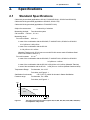
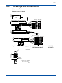
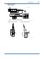
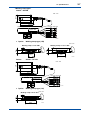
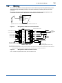
User’s Manual Model SC4AJ Conductivity Sensor IM 12D08F03-02E R IM 12D08F03-02E 7th Edition i < Introduction > Introduction Thank you for purchasing our inductive conductivity measurement system. This manual describes the method of installing for the SC4AJ. To ensure that this measurement system can be operated safely and also exhibit its full performance, be sure to read this manual before use. This manual does not describe the units in Table shown below which are the component units of the conductivity measuring system. Each of these units comes with an instruction manual, so read the applicable manuals for details of the units concerned. Manual Name IM No. SC202G, SC202SJ 2-Wire Conductivity Transmitter IM 12D08B02-01E FLXA202,FLXA21 2-Wire Liquid Analyzer IM 12A01A02-01E SC450G 4-Wire Conductivity Converter IM 12D08N05-01E Upon delivery, unpack the instrument carefully and inspect it to ensure that it was not damaged during shipment. If damage is found, retain the original packing materials (including the outer box) and then immediately notify the carrier and the relevant YOKOGAWA sales office. Make sure the model code on the label affixed to the cable agrees with your order. For the meaning of the model code, refer to the Model and Suffix code table (Section 2.2). Media No. IM 12D08F03-02E 7th Edition : Oct. 2015 (YK) All Rights Reserved Copyright © 2006, Yokogawa Electric Corporation IM 12D08F03-02E 7th Edition : Oct.28,2015-00 ii < Introduction > For the safe use of this equipment n Safety, Protection, and Modification of the Product • In order to protect the system controlled by the product and the product itself and ensure safe operation, observe the safety precautions described in this user’s manual. We assume no liability for safety if users fail to observe these instructions when operating the product. • If this instrument is used in a manner not specified in this user’s manual, the protection provided by this instrument may be impaired. • Be sure to use the spare parts approved by Yokogawa Electric Corporation (hereafter simply referred to as YOKOGAWA) when replacing parts or consumables. • Modification of the product is strictly prohibited. • The following symbols are used in the product and user’s manual to indicate that there are precautions for safety: n Notes on Handling User’s Manuals • Please hand over the user’s manuals to your end users so that they can keep the user’s manuals on hand for convenient reference. • Please read the information thoroughly before using the product. • The purpose of these user’s manuals is not to warrant that the product is well suited to any particular purpose but rather to describe the functional details of the product. • No part of the user’s manuals may be transferred or reproduced without prior written consent from YOKOGAWA. • YOKOGAWA reserves the right to make improvements in the user’s manuals and product at any time, without notice or obligation. • If you have any questions, or you find mistakes or omissions in the user’s manuals, please contact our sales representative or your local distributor. n Warning and Disclaimer The product is provided on an “as is” basis. YOKOGAWA shall have neither liability nor responsibility to any person or entity with respect to any direct or indirect loss or damage arising from using the product or any defect of the product that YOKOGAWA can not predict in advance. n Compliance with the simple apparatus requirements SC4AJ meet the simple apparatus requirements defined in the following standards. Note: TIIS certified types cannot be connected. Use the sensors under the conditions of use required by the standards. Applicable standards: ANSI/ISA-60079-11 (2014) ANSI/ISA-60079-0 (2009) CAN/CSA-C22.2 NO. 60079-11:14 CAN/CSA-C22.2 NO. 60079-0:11 방호장치 의무안전인증 고시 GB 3836.4-2010 IM 12D08F03-02E 7th Edition : Oct.28,2015-00 iii < Introduction > Conditions of use: (1) Use in combination with an internally isolated transmitter, or use with, a transmitter in combination with isolated barrier. The FLXA21 is internally isolated. (2) Upper limit of the process temperature. The upper limit of process temperature is indicated below when the sensor is used in combination with a YOKOGAWA transmitter. For FLXA21, model and suffix code below is available. FLXA21-D-□-D-EA-C1-○-A-N-LA-N-NN □: can be any value. ○: must be NN or C1. Any option code is available. For SC202S, model and suffix code below is available SC202S-A-E There are no SC202S models that meet the Korean explosion proof standards. Any option code is available. Upper limit of process temperature on the SC4AJ Transmitter used in combination Ambient temperature Ta Temperature class *1: FLXA21 40°C SC202S 60°C 40°C 60°C T6 49 49 72 72 T5 95 (*1) 64 95 (*1) 87 T4 110 99 110 110 T3 110 110 110 110 T2 110 110 110 110 T1 110 110 110 110 Care about upper limit 100°C of temperature class T5 should be taken. Other warnings are provided in the following. WARNING Handling precautions: (1) Potential electrostatic charging hazard Electrostatic charge may cause an explosion hazard. Avoid any actions that cause the generation of electrostatic charge, e.g., rubbing with a dry cloth. (2) IEC60079-14 (Electrical installations in hazardous areas) requires a label indicating ‘simple apparatus’, stick this label to this sensor if necessary. IM 12D08F03-02E 7th Edition : Oct.28,2015-00 iv < Introduction > n Symbol Marks Throughout this user’s manual, you will find several different types of symbols are used to identify different sections of text. This section describes these icons. WARNING Indicates a potentially hazardous situation which, if not avoided, could result in death or serious injury. CAUTION Indicates a potentially hazardous situation which, if not avoided, may result in minor or moderate injury. It may also be used to alert against unsafe practices. IMPORTANT Indicates that operating the hardware or software in this manner may damage it or lead to system failure. NOTE Draws attention to information essential for understanding the operation and features. IM 12D08F03-02E 7th Edition : Oct.28,2015-00 v < Introduction > After-sales Warranty n Do not modify the product. n During the warranty period, for repair under warranty consult the local sales representative or service office. Yokogawa will replace or repair any damaged parts. Before consulting for repair under warranty, provide us with the model name and serial number and a description of the problem. Any diagrams or data explaining the problem would also be appreciated. l If we replace the product with a new one, we won’t provide you with a repair report. l Yokogawa warrants the product for the period stated in the pre-purchase quotation Yokogawa shall conduct defined warranty service based on its standard. When the customer site is located outside of the service area, a fee for dispatching the maintenance engineer will be charged to the customer. n In the following cases, customer will be charged repair fee regardless of warranty period. • Failure of components which are out of scope of warranty stated in instruction manual. • Failure caused by usage of software, hardware or auxiliary equipment, which Yokogawa Electric did not supply. • Failure due to improper or insufficient maintenance by user. • Failure due to modification, misuse or outside-of-specifications operation which Yokogawa does not authorize. • Failure due to power supply (voltage, frequency) being outside specifications or abnormal. • Failure caused by any usage out of scope of recommended usage. • Any damage from fire, earthquake, storms and floods, lightning, disturbances, riots, warfare, radiation and other natural changes. n Yokogawa does not warrant conformance with the specific application at the user site. Yokogawa will not bear direct/indirect responsibility for damage due to a specific application. n Yokogawa Electric will not bear responsibility when the user configures the product into systems or resells the product. n Maintenance service and supplying repair parts will be covered for five years after the production ends. For repair for this product, please contact the nearest sales office described in this instruction manual. IM 12D08F03-02E 7th Edition : Oct.28,2015-00 Blank Page < CONTENTS > vii Model SC4AJ Conductivity Sensor IM 12D08F03-02E 7th Edition CONTENTS Introduction.....................................................................................................i For the safe use of this equipment..............................................................ii After-sales Warranty.....................................................................................v 1. General....................................................................................................... 1-1 2. Specifications............................................................................................ 2-1 3. 2.1 Standard Specifications.................................................................................... 2-1 2.2 Model and Suffix Codes.................................................................................... 2-3 2.3 Converter and transmitter suitable for SC4AJ............................................... 2-4 2.4 Spare parts......................................................................................................... 2-4 2.5 Drawings and Dimensions................................................................................ 2-5 Mounting and Wiring................................................................................. 3-1 3.1 3.2 4. 5. Mounting............................................................................................................. 3-1 3.1.1 Adapter mounting type (-AD).............................................................. 3-1 3.1.2 Welding socket type (-SA).................................................................. 3-2 3.1.3 Welding clamp type (-SB, -SC)........................................................... 3-3 Wiring.................................................................................................................. 3-4 Operation.................................................................................................... 4-1 4.1 Set of cell constant value.................................................................................. 4-1 4.2 Calibration with a solution of known conductivity........................................ 4-1 Maintenance............................................................................................... 5-1 5.1 Cleaning of the cell............................................................................................ 5-1 5.2 Checking on the cell.......................................................................................... 5-1 Customer Maintenance Parts List ......................................CMPL 12D08F03-02E Revision Information................................................................................................i IM 12D08F03-02E 7th Edition : Oct.28,2015-00 Blank Page 1. 1-1 < 1. General > General The SC4AJ is developed with the intention for the low conductivity applications found in the semiconductor, power, water and pharmaceutical industries. The SC4AJ is in a convenient compact style. The cell has been made available with either a titanium or stainless steel electrode. The electrode is the 2-electrode system with cell constants of 0.02 cm-1 or 0.10 cm-1, and with a fixed cable 3 to 20 meters in length. In response to customer demands, a variety of fittings for SC4AJ are also available. IM 12D08F03-02E 7th Edition : Oct.28,2015-00 Blank Page 2-1 < 2. Specifications > 2. Specifications 2.1 Standard Specifications Cable with pin terminals (applicable to SC100, FLXA202/FLXA21, SC202G and SC202SJ) Cable with M3 ring terminals (applicable to SC450G, SC202□/TB) Cable with M4 ring terminals (applicable to FLXA202/FLXA21) Object of measurement: Measuring principle: Conductivity of solutions Two-electrode system Cell constant: 0.02 cm-1, 0.1 cm-1 Measuring range: For a cell constant: 0.02 cm-1 In case of the combination with the SC450G, FLXA202/FLXA21,SC202G or SC202SJ: 0-0.5 μS/cm to 0-200 μS/cm In case of the combination with the SC100: 0-100 μS/cm to 0-1 mS/cm (Material: Titanium only, SC100 can not use with SC4AJ sensor made of Stainless Steel which cell constant is 0.02 cm-1) For a cell constant: 0.1 cm-1 In case of the combination with the SC450G, FLXA202/FLXA21,SC202G or SC202SJ: 0-5 μS/cm to 1 mS/cm In case of the combination with the SC100: 0-500 μS/cm to 0-5 mS/cm (Material: Titanium) In case of the combination with the SC100: 0-500 μS/cm to 1 mS/cm (Material: Stainless Steel) Temperature Range: For electrode, 0 to 110°C For holder, see Figure 2.1 Sterilization for electrode: 135°C (275°F), within 30 minutes in Steam Sterilization Pressure range: For electrode, 0 to 1 MPa For holder, see Figure 2.1 MPa 1.2 1.0 0.8 SUS316L 0.6 0.4 PVDF 0.2 0 10 20 30 40 50 60 70 80 100 120 140 ˚C F03.ai Figure 2.1 The range of tolerance of holders (option:/PS, /PF, /RS, /RF, /SA1, /SA2, /SB1, /SB2,/SC1) for temperature and pressure IM 12D08F03-02E 7th Edition : Oct.28,2015-00 2-2 < 2. Specifications > Sample solution condition: Although flow rate is not limited in measurement, air bubbles should not be mixed in the measured solutions to obtain correct measured values. Temperature sensor: Pt1000 Materials Body & Electrode: Stainless steel (316 SS) (for all Fitting-type) or Titanium (only for adapter mounting type-AD), Fluoro rubber (FKM) O-ring Isolator: PEEK Mounting adapter: Plyvinylidene difluoride (for /PF and /RF) or Stainless steel (316 SS), Stainless steel (316L SS) Weight: Sensors: Adapter mounting type (SC4AJ-S-AD-09-002-05): approx.450 g Adapter mounting type (SC4AJ-S-AD-15-002-05): approx.520 g Welding socket type (SC4AJ-S-SA-NN-002-05): approx.670 g 1 or 1.5 inch welding clamp type (SC4AJ-S-SB-NN-002-05): approx.550 g 2 inch welding clamp type (SC4AJ-S-SC-NN-002-05): approx.670 g Note: There are weight differences among SC4AJ sensors. In order to know the more accurate weight of each type of sensors, please calculate it from following information. The cable weighs 75 g/m. The SC4AJ with 0.02 cm-1 cell constant is 15 g heavier than the SC4AJ with 0.1 cm-1 cell constant. 314L SS electrode is 40 g heavier than Titanium electrode. Adapters: 3/4NPT stainless steel adapter (/PS): approx. 110 g R3/4 stainless steel adapter (/RS): approx. 110 g 3/4NPT PVDF adapter (/PF): approx. 35 g R3/4 PVDF adapter (/RF): approx. 35 g Straight welding socket (/SA1): approx. 300 g Angle welding socket 15 (/SA2): approx. 320 g Welding clamp 1 inch (/SB1): approx. 330 g Welding clamp 1.5 inch (/SB2): approx. 305 g Welding clamp 2 inch (/SC1): approx. 350 g NOTE Do not submerge the sensor itself in process water, as the seams between the mold and the metal of the sensor are not waterproof. IM 12D08F03-02E 7th Edition : Oct.28,2015-00 < 2. Specifications > 2.2 2-3 Model and Suffix Codes Model SC4AJ Suffix Code Option Code Description ........................................................... ........................ Conductivity sensor ....................... Titanium (Only for -AD) Material -T ....................... 316L SS -S ....................... Adapter mounting type Fitting type -AD ....................... Welding socket type (*1) -SA ....................... 1 or 1.5 inch welding clamp type (*2) -SB ....................... 2 inch welding clamp type (*2) -SC ....................... 9 cm (Code for -AD) Sensor length -09 ....................... 15 cm (Code for -AD) -15 ....................... fixed length (Code for -SA, -SB, -SC) -NN ....................... 0.02 cm-1 Cell constant -002 ....................... 0.1 cm-1 -010 ....................... 3 m (pin terminals) Cable length -03 ....................... 5 m (pin terminals) -05 ....................... 10 m (pin terminals) -10 ....................... 15 m (pin terminals) (*3) -15 ....................... 20 m (pin terminals) (*3) -20 ....................... 3 m (M4 ring terminals) (*5) -X1 ....................... 5 m (M4 ring terminals) (*5) -X2 ....................... 10 m (M4 ring terminals) (*5) -X3 ....................... 15 m (M4 ring terminals) (*5) -X4 ....................... 20 m (M4 ring terminals) (*5) -X5 ....................... 3 m (M3 ring terminals) (*6) -Y1 ....................... 5 m (M3 ring terminals) (*6) -Y2 ....................... 10 m (M3 ring terminals) (*6) -Y3 ....................... 15 m (M3 ring terminals) (*6) -Y4 ....................... 20 m (M3 ring terminals) (*6) -Y5 Temperature sensor -T1 ....................... Pt1000 Option *1: *2: *3: *4: *5: *6: For AD only /PS /PF /RS /RF For SA only /SA1 /SA2 For SB only /SB1 /SB2 For SC only /SC1 Oil prohibit /DG1 3/4NPT adapter 316 SS 3/4NPT adapter PVDF R3/4 adapter 316 SS R3/4 adapter PVDF Straight welding socket 316L SS Angled welding socket 15° 316L SS Welding clamp 1 inch 316L SS Welding clamp 1.5 inch 316L SS Welding clamp 2 inch 316L SS Oil-prohibited use (*4) When you select fitting type -SA, place an order on the SC4AJ with option code /SA1 or /SA2. When you select fitting type -SB, place an order on the SC4AJ with option code /SB1 or /SB2 (including seal ring), When you select fitting type -SC, place an order on the SC4AJ with option code /SC1 (including seal ring). Impossible use for the SC400G. Washing treatment of wet part with alcohol. Used for connection to FLXA202/FLXA21. Used for connection to SC450G, SC202□/TB. IM 12D08F03-02E 7th Edition : Oct.28,2015-00 < 2. Specifications > 2.3 Converter and transmitter suitable for SC4AJ FLXA202/FLXA21: 2-Wire Liquid Analyzer SC202G, SC202SJ: Two-wire conductivity transmitter SC100, SC402G, SC450G: Four-wire conductivity converter Pin Ring M4 Ring M3 Yes N.A. N.A. Yes N.A. Yes (*1) Converter: SC402G (*3) Yes N.A. N.A. Converter: SC450G (*2) N.A. Yes Yes Yes N.A. Converter Type of terminals Converter: SC100 Transmitter: SC202G, SC202SJ Analyzer: *1: *2: *3: 2.4 2-4 FLXA202/FLXA21 Applicable when option code /TB (screw terminal) specified for SC202G/SC202SJ. Both pin and M3 ring can be used for SC450G, but M3 ring are recommended. SC402G has been terminated. Spare parts The following spare parts are necessary in maintaining SC4AJ or changing the installed place. Previously procure the parts related to each conductivity sensor type. Parts No. K9670MA K9670MK K9670MP K9670MT K9670MU K9670MV K9670MW K9670MD K9670ME K9670MB K9670MC K9670ML K9670MQ Description O-ring set for -SA Seal rings for /SB1 or /SB2 Seal rings for /SC1 3/4 NPT Stainless steel adapter for -AD 3/4 NPT PVDF Adapter for -AD R3/4 Stainless steel adapter for -AD R3/4 PVDF Adapter for -AD Angled welding socket and mounting nut for -SA Staight welding socket for -SA Angled welding socket for -SA Straight welding socket for -SA Welding clamp 1 or 1.5 inch for -SB Welding clamp 2 inch for -SC IM 12D08F03-02E 7th Edition : Oct.28,2015-00 2-5 < 2. Specifications > Drawings and Dimensions ˂Adapter mounting type˃ SC4AJ-□-AD-09 ø19.05 Sensor length: 09 (9 cm) Unit : mm 90 Pin-type Ring-type Cable length (3m, 5m, 10m, 15m, 20m) Approx. 350 F04.ai 152 ø19.05 Unit : mm Cable length (3m, 5m, 10m, 15m, 20m) Pin-type Ring-type Approx. 350 F05.ai ● Option: Adapter mounting type (-AD) /PS (Stainless Steel) /PF (PVDF) /RS (Stainless Steel) /RF (PVDF) Unit : mm Approx. 49 2.5 3/4NPT or R3/4 *1 *1 /PS or /PF : 3/4NPT /RS or /RF : R3/4 F06.ai IM 12D08F03-02E 7th Edition : Oct.28,2015-00 < 2. Specifications > 2-6 ˂Welding socket type˃ ø19.05 SC4AJ-□-SA-NN Unit : mm ø38 ø33.8 ø24.9 O-ring 95 5 130.5 Approx. 185 Pin-type Ring-type Cable length (3m, 5m, 10m, 15m, 20m) Approx. 350 F07.ai ● Option: Welding socket type (-SA) Unit : mm Straight welding socket: /SA1 Angled welding socket: /SA2 51 55 ø42 15° 8.5 et Sock ess n k thic ) ( 56.3 8.5 Socket thickness ø42 (43.5) F08.ai IM 12D08F03-02E 7th Edition : Oct.28,2015-00 2-7 < 2. Specifications > ˂Welding clamp type˃ SC4AJ-□-SB-NN ø19.05 ø50.5 Unit : mm 70 89.7 6.35 Approx. 150 Pin-type Ring-type Cable length (3m, 5m, 10m, 15m, 20m) Approx. 350 F09.ai ● Option: Welding clamp type (-SB) Unit : mm Welding clamp 1.5 inch: /SB2 12.7 12.7 Welding clamp 1 inch: /SB1 ø38.1 ø25.4 F10.ai Sensor SC4AJ-□-SC-NN ø64 ø19.05 Unit : mm 80 6.35 115.7 Approx. 170 Cable length (3m, 5m, 10m, 15m, 20m) Pin-type Ring-type Approx. 350 F11.ai ● Option: Welding clamp type (-SC) Unit : mm 12.7 Welding clamp 2 inch: /SC1 ø50.8 F12.ai IM 12D08F03-02E 7th Edition : Oct.28,2015-00 Blank Page 3-1 < 3. Mounting and Wiring > 3. Mounting and Wiring 3.1 Mounting Before mounting an electrode in a process plant environment, the following points should be considered. • The electrode must be mounted in the process in such a way that the flow through it represents the true composition of the liquid. The flow through the cell should be uninterrupted and the cell should not be mounted at a dead angle. • A cell must be immersed in the process liquid to a level above the outlet to ensure an uninterrupted liquid path between the electrodes. • The sensor should be mounted in such a way to allow safe and easy removal for maintenance, and to release the process liquid pressure for the removal. • Check the process pressure for mounting place is below the pressure range of the SC4AJ and its adapter. • Do not submerge the sensor itself in process water, as the seams between the mold and the metal of the sensor are not waterproof. IMPORTANT When ultra-pure water flows through plastic pipe, electrostatic charge may be produced. When the sensor is installed on this plastic pipe, the electrostatic charge goes through the sensor, and into a converter circuit through terminals on the converter which is connected to the sensor. This electrostatic charge will discharge and damage electronic parts on the converter circuit. 3.1.1 Adapter mounting type (-AD) Option code /PS, /RS (material: stainless steel) and /PF, /RF (material: PVDF) are for the adapters special for the Adapter Mounting Type of the SC4AJ. As for their dimensions, refer to section 2.5. Mounting is done by the combination of the sensor with the adapter. Mount the sensor by the correct insertion order of adapter parts according to Figure 3.1. Note: Screwing the nut by the incorrect order of the parts can cause trouble of the mounting system and sealing defective. Tighten the nut with a torque of approx. 190 N•m (19 kgf•m). This corresponds approximately to first tightening with the fingers, then using a spanner or the like to tighten by one and a quarter turns. Nut Adapter (/PS, /PF /RS, /RF) F3-1.ai Figure 3.1 Mounted sensor (SC4AJ-AD) IM 12D08F03-02E 7th Edition : Oct.28,2015-00 3.1.2 3-2 < 3. Mounting and Wiring > Welding socket type (-SA) Option code /SA1 and /SA2 are for the adapters special for the Welding Socket Type of the SC4AJ. As for their dimensions, refer to section 2.5. As shown in Figure 3.2, weld the welding socket to a pipe in which a process liquid flows. After inserting the SC4AJ sensor into the welding socket, screw the nut with your hand. Note: Before inserting the sensor, check the following matter. • The socket is cooled to room temperature after welding is done. • The O-ring is attached to the sensor. Nut O-ring Welding socket F3-2.ai Figure 3.2 Mounting sensor (SC4AJ-SA) IM 12D08F03-02E 7th Edition : Oct.28,2015-00 3.1.3 3-3 < 3. Mounting and Wiring > Welding clamp type (-SB, -SC) Option code /SB1 and /SB2 are for the adapters special for the Welding Socket Type of the SC4AJ (-SB), and /SC1 is for the SC4AJ (-SC). As for their dimensions, refer to section 2.5. As shown in Figure 3.3, weld the flange to a pipe in which a process liquid flows. Insert the SC4AJ sensor with the seal ring into the flange. Fix the sensor with the clamp. Seal ring Welding clamp Clamp Flange F3-3.ai Figure 3.3 Mounted sensor (SC4AJ-SB, -SC) IM 12D08F03-02E 7th Edition : Oct.28,2015-00 3.2 3-4 < 3. Mounting and Wiring > Wiring The conductivity sensor can be used with two-wire Liduid Analyzer (FLXA202/FLXA21) or twowire conductivity transmitter (SC202) or four-wire conductivity converter (SC100, SC402G, SC450G). To connect the sensor and transmitter/converter, simply match the terminal numbers in the transmitter/converter with the identification numbers on the cable ends. White Brown 11 12 13 14 15 16 Green Yellow Black Red Temperature Electrode F3-4.ai Applicable Converter / Transmitter: SC402G/SC450G, SC202/FLXA202/FLXA21 Figure 3.4 Wiring between SC4AJ and converter/transmitter Cable conductor number Contact output 1 (NC) 1 Terminal name S1(NC) 11 15 Contact output 1 (NO) 2 S1(NO) C2 12 13 3 COM1 S 13 Terminal name C1 Contact output 2 4 S2 I2 14 14 Contact output 3 5 S3 I1 15 16 Contact output 4 6 S4 16 T1 17 11 L 8 L T2 18 12 N 9 N mA(1) 19 mA(2) 20 7 10 COM2 SC4AJ Conductivity sensor Ground to earth (grounding resistance 100Ω or less) Analog output Shield Converter Rear View Ground to earth (grounding resistance 100Ω or less) Note: Terminals are M3.5 screws. Caution: Extra care must be taken the making connection between the SC4AJ sensor and the SC100 converter since the number marker on each sensor cable conductor does not correspond to the one indicated on the converter's terminal block. Figure 3.5 Wiring between SC4AJ and SC100 converter Note: For details of wiring with SC100 converter, refer to IM 12D11A01-01E. IM 12D08F03-02E 7th Edition : Oct.28,2015-00 4. < 4. Operation > 4-1 Operation Before operation, check following items. Check that sensor cable connections are correct. Check that there are no problems in flowing the measured solution. Check piping connections for measured solution leaks. Check that pressure and temperature are within the permitted operating ranges. Check that the solution level reaches the measured solution outlet when the flow of measured solution is started. 4.1 Set of cell constant value Enter the factory calibrated cell constant value for the converter or the transmitter connected to the SC4AJ. The factory calibrated cell constant value is labelled on the cable. As for the procedure of the entry, refer to Instruction Manual of the converter or the transmitter. 4.2 Calibration with a solution of known conductivity The cell constant is determined in laboratory conditions. It is possible that slight variations in the cell constant may occur dependant on the installation. This possible error can be corrected by recalibrating with a solution of known conductivity value. NOTE The specific conductivity value of the solution of known value must be near the value of the liquid to be measured. Specific conductivity is highly temperature dependent, therefore in the above calibration procedure the temperature of the cell and the liquid should be allowed to equalize and should be accurately measured with a calibrated thermometer. IM 12D08F03-02E 7th Edition : Oct.28,2015-00 Blank Page 5. 5-1 < 5. Maintenance > Maintenance If the cell becomes fouled, an insulating layer may be formed on the electrodes. As the result, an apparent increase in cell constant may occur, giving a measuring error. Check and maintain the sensor in case of an error occurrence. 5.1 Cleaning of the cell A. For lime, hydroxides, etc. : 5 to 10% solution of hydrochloric acid is recommended. B. For organic foul (oil, fats, etc.) : they can be removed with ethyl alcohol or acetone. C. For algae bacteria or moulds : use a chlorinated solution (domestic bleach). D. For normal applications : hot water with domestic washing-up liquid will be effective. WARNING Never use hydrochloric acid and domestic bleach simultaneously. The liberation of the very poisonous gas chlorine will result. 5.2 Checking on the cell After cleaning the sensor, check the condition of it with the eye. Measure the resistances of the sensor for the following procedure. A. Fully dry the sensor, specially the cell. B. Measure the resistivity between cable terminals. C. The combination of the terminals, and standard resistance are as follows. Combination of TerminalsStandard Resistance 11 and 12 1000 to 1137 Ω (room temperature) 11 and 13, 12 and 13, 12 and 14, 12 and 15 more than 100 MΩ 13 and 14, 15 and 16 less than 10 Ω IM 12D08F03-02E 7th Edition : Oct.28,2015-00 Blank Page Customer Maintenance Parts List Model SC4AJ Conductivity Sensor AdapterWelding Socket SC4AJ--AD-09 SC4AJ--SA-NN Option code: /SA1 /SA2 1 2 ( 3, 4) 5 ( 3, 6) 7 Welding Clamp SC4AJ--SB-NN.../SB1, /SB2 9 8 10 SC4AJ--SB-NN.../SC1 12 11 13 All Rights Reserved, Copyright © 2006, Yokogawa Electric Corporation. Subject to change without notice. CMPL 12D08F03-02E 1st Edition : May. 2006 (YK) 2 Item 1 Part No. Qty K9670MU K9670MT K9670MW K9670MV 1 1 1 1 Description Adapter for suffix code -AD 3/4NPT PVDF adapter 3/4NPT Stainless steel adapter R3/4 PVDF adapter R3/4 Stainless steel adapter 2 3 4 K9670ME 1 K9670MF 1 K9670MC 1 Straight welding socket and mounting nut for /SA1 Nut Socket 5 6 K9670MD 1 K9670MB 1 Angled welding socket and mounting nut for /SA2 Socket 7 K9670MA 1 O-ring 8 9 K9670ML 1 K9670MK 1 Welding clamp for /SB1, /SB2 Seal ring for /SB1, /SB2 K9670MM 1 K9670MN 1 Welding socket For /SB1 For /SB2 K9670MQ 1 K9670MP 1 K9670MR 1 Welding clamp for /SC1 Seal ring for /SC1 Welding socket for /SC1 10 11 12 13 CMPL 12D08F03-02E 1st Edition : May 2006 (YK)) i Revision Information Title Manual No. : Model SC4AJ Conductivity Sensor : IM 12D08F03-02E Oct. 2015/7th Edition Added FLXA202 P i, P2-1, P2-3, P2-4, P3-4. Unification of the material name P2-1, P2-2. Apr. 2015/6th Edition P ii to iii Added to “■ Compliance with the simple apparatus requirements”. P3-1 Symbol Marks of “IMPORTANT” added to “3.1 Mounting”. Jul. 2013/5th Edition P. 2-2 P. 2-3 Some revision of material (option code of /PS, /RS changed); Some revision of option code (material of /PS, /RS changed to SUS316). Jun. 2011/4th Edition Pi Manual No. of FLXA21 added; P2 FLXA21 added; P4 Some of description for MS-code modified (M4 ring terminal for FLXA21 added); P5 FLXA21 added to combination of sensor and converters; P6 to P9 Some of cable label description on drawings and dimensions modified. Mar. 2010/3rd Edition Illustrations of each figure replaced more clearly drawings, no contents changed. Jan. 2008/2nd Edition Ring terminals added for SC450G converter. May 2006/1st Edition Newly published n If you want to have more information about Yokogawa products, you can visit Yokogawa’s home page at the following web site. Home page: http://www.yokogawa.com/an IM 12D08F03-02E 7th Edition : Oct.28,2015-00 Blank Page


![SC450G 導電率変換器 [スタイル:S2]](http://vs1.manualzilla.com/store/data/006528460_2-777bddcbd7f006e5f45ca478d2d1b911-150x150.png)
![Model SC450G [Style: S2] Conductivity](http://vs1.manualzilla.com/store/data/005772923_1-d910951678550c5451dfdc47fd4527d0-150x150.png)