1
EC301 Manual
October 2, 2014
Contents
1 General information
1.1
Safety and preparation for use . . . . . .
1.2
Symbols you may find on SRS products .
1.3
Specifications . . . . . . . . . . . . . . .
1.4
Serial number and firmware revision . . .
.
.
.
.
.
.
.
.
.
.
.
.
.
.
.
.
.
.
.
.
.
.
.
.
.
.
.
.
.
.
.
.
.
.
.
.
.
.
.
.
.
.
.
.
.
.
.
.
.
.
.
.
.
.
.
.
.
.
.
.
.
.
.
.
.
.
.
.
.
.
.
.
.
.
.
.
.
.
.
.
.
.
.
.
.
.
.
.
.
.
.
.
.
.
.
.
.
.
.
.
.
.
.
.
.
.
.
.
.
.
.
.
.
.
.
.
5
5
6
7
16
2 EC301 basics
2.1
Software . . . . . . . . . . . . . . .
2.2
Functional block diagram . . . . . .
2.3
Polarity convention . . . . . . . . .
2.4
Connecting the EC19 to the EC301
2.4.1
Necessary Items . . . . . .
2.4.2
Steps . . . . . . . . . . . .
.
.
.
.
.
.
.
.
.
.
.
.
.
.
.
.
.
.
.
.
.
.
.
.
.
.
.
.
.
.
.
.
.
.
.
.
.
.
.
.
.
.
.
.
.
.
.
.
.
.
.
.
.
.
.
.
.
.
.
.
.
.
.
.
.
.
.
.
.
.
.
.
.
.
.
.
.
.
.
.
.
.
.
.
.
.
.
.
.
.
.
.
.
.
.
.
.
.
.
.
.
.
.
.
.
.
.
.
.
.
.
.
.
.
.
.
.
.
.
.
.
.
.
.
.
.
.
.
.
.
.
.
.
.
.
.
.
.
.
.
.
.
.
.
.
.
.
.
.
.
.
.
.
.
.
.
.
.
.
.
.
.
.
.
.
.
.
.
.
.
.
.
.
.
17
17
17
19
19
19
20
. . . .
. . . .
. . . .
. . . .
. . . .
. . . .
. . . .
. . . .
. . . .
. . . .
. . . .
. . . .
. . . .
. . . .
. . . .
. . . .
. . . .
. . . .
. . . .
. . . .
. . . .
. . . .
. . . .
. . . .
. . . .
. . . .
. . . .
. . . .
input
. . . .
. . . .
. . . .
. . . .
.
.
.
.
.
.
.
.
.
.
.
.
.
.
.
.
.
.
.
.
.
.
.
.
.
.
.
.
.
.
.
.
.
.
.
.
.
.
.
.
.
.
.
.
.
.
.
.
.
.
.
.
.
.
.
.
.
.
.
.
.
.
.
.
.
.
.
.
.
.
.
.
.
.
.
.
.
.
.
.
.
.
.
.
.
.
.
.
.
.
.
.
.
.
.
.
.
.
.
.
.
.
.
.
.
.
.
.
.
.
.
.
.
.
.
.
.
.
.
.
.
.
.
.
.
.
.
.
.
.
.
.
.
.
.
.
.
.
.
.
.
.
.
.
.
.
.
.
.
.
.
.
.
.
.
.
.
.
.
.
.
.
.
.
.
.
.
.
.
.
.
.
.
.
.
.
.
.
.
.
.
.
.
.
.
.
.
.
.
.
.
.
.
.
.
.
.
.
.
.
.
.
.
.
.
.
.
.
.
.
.
.
.
.
.
.
.
.
.
.
.
.
.
.
.
.
.
.
.
.
.
.
.
.
.
.
.
.
.
.
.
.
.
.
.
.
.
.
.
.
.
.
.
.
.
.
.
.
.
.
.
.
.
.
.
.
.
.
.
.
.
.
.
.
.
.
.
.
.
.
.
.
.
.
.
.
.
.
.
.
.
.
.
.
.
.
.
.
.
.
.
.
.
.
.
.
.
.
.
.
.
.
.
.
.
.
.
.
.
.
.
.
.
.
.
.
.
.
.
.
.
.
.
.
.
.
.
.
.
.
.
.
.
.
.
.
.
.
.
.
.
.
.
.
.
.
.
.
.
.
.
.
.
.
.
.
.
.
.
.
.
.
.
.
.
.
.
.
.
.
.
.
.
.
.
.
.
.
.
.
.
.
.
.
.
.
.
.
.
.
.
.
.
.
.
.
.
.
.
.
.
.
.
.
.
.
.
.
.
.
.
.
.
.
.
.
.
.
.
.
.
.
.
.
.
.
.
.
.
.
.
.
.
.
.
.
.
.
.
.
.
.
.
.
.
.
.
.
.
.
.
.
.
.
.
.
.
.
.
.
.
.
.
.
.
.
.
.
.
.
.
.
.
.
.
.
.
.
.
.
.
.
.
.
.
.
.
.
.
.
.
.
.
.
.
.
.
.
.
.
.
.
.
.
.
.
.
.
.
.
.
.
.
.
.
.
.
.
.
.
.
.
.
.
.
.
.
.
.
.
.
.
.
.
.
.
.
.
.
.
.
.
.
.
.
.
.
.
.
.
.
.
.
.
.
.
.
.
.
.
.
.
.
.
.
.
.
.
.
.
.
.
.
.
.
.
.
.
.
.
.
.
.
.
.
.
.
.
.
.
.
.
.
.
.
.
.
.
.
.
.
.
.
.
.
.
.
.
.
.
.
.
.
.
.
.
.
.
.
.
.
.
.
.
.
.
.
.
.
.
.
.
.
.
.
.
.
.
.
.
.
.
.
.
.
.
.
.
.
.
.
.
.
.
.
.
.
.
.
.
.
.
.
.
.
.
.
.
.
.
.
.
.
.
.
.
.
.
.
.
.
.
.
21
21
21
22
22
22
23
23
23
24
24
25
26
27
28
29
29
30
31
32
32
32
33
33
33
34
36
37
38
39
40
41
42
43
.
.
.
.
.
.
.
.
.
.
.
.
.
.
.
.
.
.
3 Operation
3.1
Front panel . . . . . . . . . . . . . . . . . . . .
3.1.1
Power-on reset . . . . . . . . . . . . . .
3.1.2
Bandwidth limit . . . . . . . . . . . . .
3.1.3
CE limit . . . . . . . . . . . . . . . . .
3.1.4
Cell . . . . . . . . . . . . . . . . . . . .
3.1.5
External electrometer . . . . . . . . . .
3.1.6
Voltage . . . . . . . . . . . . . . . . . .
3.1.7
Current . . . . . . . . . . . . . . . . . .
3.1.8
Mode . . . . . . . . . . . . . . . . . . .
3.1.9
Rotating electrode . . . . . . . . . . . .
3.1.10
Analog output . . . . . . . . . . . . . .
3.1.11
Current range . . . . . . . . . . . . . .
3.1.12
IR compensation . . . . . . . . . . . . .
3.1.13
External input . . . . . . . . . . . . . .
3.1.14
Measurement setup/control . . . . . . .
3.1.15
Knob . . . . . . . . . . . . . . . . . . .
3.1.16
Configure . . . . . . . . . . . . . . . . .
3.1.17
Remote status . . . . . . . . . . . . . .
3.2
Rear panel . . . . . . . . . . . . . . . . . . . . .
3.2.1
Power entry . . . . . . . . . . . . . . .
3.2.2
GPIB interface . . . . . . . . . . . . . .
3.2.3
Ethernet interface . . . . . . . . . . . .
3.2.4
Current interrupt synchronization . . .
3.2.5
Timebase synchronization input . . . .
3.2.6
Scan trigger input . . . . . . . . . . . .
3.2.7
Program E/I output . . . . . . . . . .
3.2.8
Scan synchronization output . . . . . .
3.2.9
Auxiliary ADC inputs (1-3) . . . . . .
3.2.10
Resistance temperature detector (RTD)
3.2.11
Grounding posts . . . . . . . . . . . . .
3.2.12
Raw analog outputs . . . . . . . . . . .
3.2.13
CE monitor . . . . . . . . . . . . . . .
3.2.14
Synchronous ADC input . . . . . . . .
4 Making cell connections
44
4.1
Floating operation . . . . . . . . . . . . . . . . . . . . . . . . . . . . . . . . . . . . . . . . . 45
4.1.1
Overview . . . . . . . . . . . . . . . . . . . . . . . . . . . . . . . . . . . . . . . . . . 45
4.1.2
Grounded Working Electrode . . . . . . . . . . . . . . . . . . . . . . . . . . . . . . . 46
2
Contents
4.2
4.1.3
Grounded Counter Electrode . . . . . . . . . . . . . . . . . . . . . . . . . . . . . . .
Working with grounded electrodes . . . . . . . . . . . . . . . . . . . . . . . . . . . . . . . . .
5 Performing scans using the front panel
5.1
Setting scan parameters – potentiostat mode . . . . .
5.1.1
Cyclic voltammetry (CV) . . . . . . . . . . .
5.1.2
Linear sweep voltammetry (LSV) . . . . . .
5.1.3
Steps . . . . . . . . . . . . . . . . . . . . . .
5.1.4
Holds . . . . . . . . . . . . . . . . . . . . . .
5.2
Setting scan parameters – galvanostat mode . . . . .
5.2.1
Cyclic current ramp . . . . . . . . . . . . . .
5.2.2
Linear current ramp . . . . . . . . . . . . . .
5.2.3
Current step . . . . . . . . . . . . . . . . . .
5.2.4
Current hold . . . . . . . . . . . . . . . . . .
5.3
Basic scan controls . . . . . . . . . . . . . . . . . . .
5.4
Triggering scans . . . . . . . . . . . . . . . . . . . . .
5.4.1
Triggering a scan from the front panel . . . .
5.4.2
Triggering a scan with the scan trigger input
5.4.3
Triggering a scan from the remote interface .
5.5
Setting the end of scan condition . . . . . . . . . . .
.
.
.
.
.
.
.
.
.
.
.
.
.
.
.
.
.
.
.
.
.
.
.
.
.
.
.
.
.
.
.
.
.
.
.
.
.
.
.
.
.
.
.
.
.
.
.
.
.
.
.
.
.
.
.
.
.
.
.
.
.
.
.
.
.
.
.
.
.
.
.
.
.
.
.
.
.
.
.
.
.
.
.
.
.
.
.
.
.
.
.
.
.
.
.
.
.
.
.
.
.
.
.
.
.
.
.
.
.
.
.
.
.
.
.
.
.
.
.
.
.
.
.
.
.
.
.
.
.
.
.
.
.
.
.
.
.
.
.
.
.
.
.
.
.
.
.
.
.
.
.
.
.
.
.
.
.
.
.
.
.
.
.
.
.
.
.
.
.
.
.
.
.
.
.
.
.
.
.
.
.
.
.
.
.
.
.
.
.
.
.
.
.
.
.
.
.
.
.
.
.
.
.
.
.
.
.
.
.
.
.
.
.
.
.
.
.
.
.
.
.
.
.
.
.
.
.
.
.
.
.
.
.
.
.
.
.
.
.
.
.
.
.
.
.
.
.
.
.
.
.
.
.
.
.
.
.
.
.
.
.
.
.
.
.
.
.
.
.
.
.
.
.
.
.
.
.
.
.
.
.
.
.
.
.
.
.
.
.
.
.
.
.
.
.
.
.
.
.
.
.
.
.
.
.
.
.
.
.
.
.
.
.
.
.
.
.
.
.
.
.
.
.
.
.
.
.
.
.
.
.
.
.
.
.
.
.
.
.
.
.
.
.
.
.
.
.
.
.
.
.
.
6 Using the EC301 with a frequency response analyzer (FRA)
7 Remote programming
7.1
Command syntax . . . . . . . . . . . . . . . . . . .
7.2
Argument formats . . . . . . . . . . . . . . . . . . .
7.3
Detailed command list . . . . . . . . . . . . . . . .
7.3.1
Firmware and hardware revisions . . . . .
7.3.2
Program E/I setup (with external input) .
7.3.3
Control loop commands . . . . . . . . . . .
7.3.4
Cell switch . . . . . . . . . . . . . . . . . .
7.3.5
IR compensation . . . . . . . . . . . . . . .
7.3.6
Scan trigger commands . . . . . . . . . . .
7.3.7
Rotating working electrode commands . .
7.3.8
Analog output commands . . . . . . . . . .
7.3.9
Voltage (E) measurement setup . . . . . .
7.3.10
Current (I) measurement setup . . . . . .
7.3.11
Reading single measurement results . . . .
7.3.12
Streaming data . . . . . . . . . . . . . . .
7.3.13
Remote interface commands . . . . . . . .
7.3.14
Timebase commands . . . . . . . . . . . .
7.3.15
Status reporting commands . . . . . . . . .
7.3.16
Pulsed waveform generation commands . .
7.3.17
Ramp generation commands . . . . . . . .
7.3.18
Arbitrary waveform generation commands
7.3.19
Reading temperature measurements . . . .
7.4
Programming examples . . . . . . . . . . . . . . . .
7.4.1
Normal pulse . . . . . . . . . . . . . . . . .
7.4.2
Cyclic voltammetry . . . . . . . . . . . . .
7.4.3
Current interrupt IR compensation . . . .
7.4.4
Arbitrary waveform . . . . . . . . . . . . .
.
.
.
.
.
.
.
.
.
.
.
.
.
.
.
.
.
.
.
.
.
.
.
.
.
.
.
.
.
.
.
.
.
.
.
.
.
.
.
.
.
.
.
.
.
.
.
.
.
.
.
.
.
.
.
.
.
.
.
.
.
.
.
.
.
.
.
.
.
.
.
.
.
.
.
.
.
.
.
.
.
.
.
.
.
.
.
.
.
.
.
.
.
.
.
.
.
.
.
.
.
.
.
.
.
.
.
.
.
.
.
.
.
.
.
.
.
.
.
.
.
.
.
.
.
.
.
.
.
.
.
.
.
.
.
.
.
.
.
.
.
.
.
.
.
.
.
.
.
.
.
.
.
.
.
.
.
.
.
.
.
.
46
47
50
50
50
52
54
56
57
57
58
59
60
61
61
61
61
61
61
63
.
.
.
.
.
.
.
.
.
.
.
.
.
.
.
.
.
.
.
.
.
.
.
.
.
.
.
.
.
.
.
.
.
.
.
.
.
.
.
.
.
.
.
.
.
.
.
.
.
.
.
.
.
.
.
.
.
.
.
.
.
.
.
.
.
.
.
.
.
.
.
.
.
.
.
.
.
.
.
.
.
.
.
.
.
.
.
.
.
.
.
.
.
.
.
.
.
.
.
.
.
.
.
.
.
.
.
.
.
.
.
.
.
.
.
.
.
.
.
.
.
.
.
.
.
.
.
.
.
.
.
.
.
.
.
.
.
.
.
.
.
.
.
.
.
.
.
.
.
.
.
.
.
.
.
.
.
.
.
.
.
.
.
.
.
.
.
.
.
.
.
.
.
.
.
.
.
.
.
.
.
.
.
.
.
.
.
.
.
.
.
.
.
.
.
.
.
.
.
.
.
.
.
.
.
.
.
.
.
.
.
.
.
.
.
.
.
.
.
.
.
.
.
.
.
.
.
.
.
.
.
.
.
.
.
.
.
.
.
.
.
.
.
.
.
.
.
.
.
.
.
.
.
.
.
.
.
.
.
.
.
.
.
.
.
.
.
.
.
.
.
.
.
.
.
.
.
.
.
.
.
.
.
.
.
.
.
.
.
.
.
.
.
.
.
.
.
.
.
.
.
.
.
.
.
.
.
.
.
.
.
.
.
.
.
.
.
.
.
.
.
.
.
.
.
.
.
.
.
.
.
.
.
.
.
.
.
.
.
.
.
.
.
.
.
.
.
.
.
.
.
.
.
.
.
.
.
.
.
.
.
.
.
.
.
.
.
.
.
.
.
.
.
.
.
.
.
.
.
.
.
.
.
.
.
.
.
.
.
.
.
.
.
.
.
.
.
.
.
.
.
.
.
.
.
.
.
.
.
.
.
.
.
.
.
.
.
.
.
.
.
.
.
.
.
.
.
.
.
.
.
.
.
.
.
.
.
.
.
.
.
.
.
.
.
.
.
.
.
.
.
.
.
.
.
.
.
.
.
64
64
64
65
65
65
68
70
71
73
74
75
77
78
80
82
86
89
90
100
106
111
116
117
117
118
119
120
Bibliography
121
A Measuring cell voltages at the cell
122
3
Contents
B Pinouts
124
B.1 Cell interface (25 pins) . . . . . . . . . . . . . . . . . . . . . . . . . . . . . . . . . . . . . . . 124
B.2 RTD interface (5 pins) . . . . . . . . . . . . . . . . . . . . . . . . . . . . . . . . . . . . . . . 124
C Major symbols and abbreviations
126
Alphabetical command index
127
4
1
General information
1
1.1
General information
Safety and preparation for use
Warning
Dangerous voltages, capable of causing injury or death, are present in this instrument. Use
extreme caution whenever the instrument covers are removed. Do not remove the covers while
the unit is plugged into a live outlet.
Line fuse
Verify that the correct line fuse(s) are installed before connecting the line cord. Fuse size is 3AB/3AG
“slo-blo” (φ6.3 × 32 mm). For 100 V/120 V, use a single 3 A fuse; for 220 V/240 V, use two 1.5 A fuses.
Line cord
The EC301 has a detachable, three-wire power cord for connection to the power source and to a protective
ground. The exposed metal parts of the instrument are connected to the outlet ground to protect against
electrical shock. Always use an outlet which has a properly connected protective ground.
Service
Do not attempt to service or adjust this instrument unless another person, capable of providing first aid or
resuscitation, is present.
Do not install substitute parts or perform any unauthorized modification to this instrument. Contact the
factory for instructions on how to return the instrument for authorized service and adjustment.
5
EC301 Potentiostat/Galvanostat/ZRA
1
General information
1.2
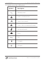
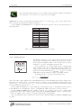
1.2 Symbols you may find on SRS products
Symbols you may find on SRS products
Symbol
Description
Alternating current
Caution - risk of electric shock
Frame or chassis terminal
Caution - refer to accompanying documents
Earth (ground) terminal
Battery
Fuse
On (supply)
Off (supply)
6
EC301 Potentiostat/Galvanostat/ZRA
1
General information
1.3
1.3 Specifications
Specifications
Voltage and current measurement accuracy
• Voltage measurement accuracy
±0.2% of reading (VRE − VWE SENSE) ± 5mV
• Current measurement accuracy, 1 A range
±0.5% of reading (IWE ) ± 0.2% of range
• Current measurement accuracy, other ranges
±0.2% of reading (IWE ) ± 0.2% of range
• Power amplifier
– Compliance voltage
≥ ±30V full compliance
– Maximum output current
≥ ±1A
– Slew rate (power amplifier in isolation)
≥ 10V/µs
– Output short-circuit protected
7
EC301 Potentiostat/Galvanostat/ZRA
1
General information
1.3 Specifications
Potentiostat mode
• Applied potential accuracy:
Potential versus reference within
±5V
±10V
±15V
Accuracy
±0.2% of setting ± 5mV
±0.5% of setting ± 5mV
±1% of setting ± 5mV
• Applied potential resolution:
Mode
General (potential set with thumbwheel or remote interface)
Performing an automatic scan (CV or LSV)
Resolution
500µV
200µV
• Noise and ripple
< 20µVrms (1Hz → 10kHz)
• Applied E range
±15V versus reference (|CE| <30V versus signal ground)
8
EC301 Potentiostat/Galvanostat/ZRA
1
General information
1.3 Specifications
Galvanostat mode
• Applied current accuracy:
±0.5% of setting ±0.2% of current range, 1 A range
±0.2% of setting ±0.2% of current range, all other ranges
ZRA mode
• Voltage offset
CE sense and WE sense electrodes held within 5 mV of each other
• Output current
1 A range: −1 A min, +1 A max
All other ranges: −2× full scale min, +2× full scale max
9
EC301 Potentiostat/Galvanostat/ZRA
1
General information
1.3 Specifications
General control loop
• Bandwidth control
10Hz, 100Hz, 1kHz, 10kHz, 100kHz, >1MHz
(10kΩ resistive load, < 100µA output current)
Bandwidth limits
• Compliance limiting
Cell current ICE
≤10mA
≤1A
Voltage limit accuracy
10
Accuracy
±250 mV
±1V
EC301 Potentiostat/Galvanostat/ZRA
1
General information
1.3 Specifications
IR compensation
• Current interrupt
Switching time (on → off)
Interrupt time
Interrupt frequency
< 5µs (1 kΩ resistive load)
100µs → 1s
0.1 Hz → 300 Hz
• Positive feedback
Range
Irange
1A
100 mA
10 mA
1 mA
100 µA
10 µA
1 µA
100 nA
10 nA
1 nA
Resolution
1 mΩ for 1A range
1 MΩ for 1nA range
11
Ru
0→3Ω
0 → 30 Ω
0 → 300 Ω
0 → 3 kΩ
0 → 30 kΩ
0 → 300 kΩ
0 → 3 MΩ
0 → 30 MΩ
0 → 300 MΩ
0 → 3 GΩ
EC301 Potentiostat/Galvanostat/ZRA
1
General information
1.3 Specifications
General system
• Remote interfaces
LAN (10/100 base-T Ethernet)
GPIB (IEEE-488)
• Dimensions (W × H × D)
– Main box
17 × 18.5 × 5.25 inches
– External box
3.25 × 4.75 × 2.5 inches
– Umbilical
36 inches
– Weight
– Power
• RTD measurement
– Temperature sensor
User supplied 100Ω Pt RTD, α = 0.00385 Ω/Ω/℃
– Range
−100 ℃ to +200 ℃
– Resistance measurement accuracy
±0.3 Ω
12
EC301 Potentiostat/Galvanostat/ZRA
1
General information
1.3 Specifications
Front panel connectors
• External input
±15V analog input in potentiostat mode, ±2V in galvanostat mode
Input impedance: 10kΩ k 50pF
• Rotating electrode output BNC
0→10V analog output
Accuracy: ±1% of setting ±5mV
Output impedance: 10Ω
10mA max output current
• Voltage (E) output BNC
±15V analog output
Accuracy: ±0.2% of VRE − VWE Sense ± 5 mV
Output impedance: 50Ω
10mA max output current
• Current (I) output BNC
±2V analog input
Accuracy: IWE within ±0.5% of (VBNC × Irange ) ± 0.2% × Irange , 1 A range
Accuracy: IWE within ±0.2% of (VBNC × Irange ) ± 0.2% × Irange , other ranges
Output impedance: 50Ω
10mA max output current
13
EC301 Potentiostat/Galvanostat/ZRA
1
General information
1.3 Specifications
Rear panel connectors
• Timebase input BNC
Frequency: 10MHz
Level: 1Vpp (nominal)
• TTL measurement synchronization BNCs
Current interrupt and scan synchronization outputs, scan trigger input
• Program E/I output BNC
±15V analog output
Accuracy: ±0.2% of total program voltage (internal sources + external input) ± 5 mV
Output impedance: 10Ω
10mA max output current
• Auxiliary ADC input BNCs
Three ±10V analog to digital inputs
input impedance: 100kΩ
1mV resolution
• Signal / floating ground banana jacks
Signal ground ohmically connected to chassis ground
Floating ground can float ±8 V relative to signal ground
Signal/floating ground isolation: 10 MΩ
• RTD input
5-pin connector for Pt RTD temperature probe
• Raw E output BNC
±15V analog output
Accuracy: ±0.2% of VRE − VWE SENSE ± 5mV
Output impedance: 50Ω
10mA max output current
• Raw I output BNC
±2V analog input
Accuracy: IWE within ±0.5% of (VBNC × Irange ) ± 0.2% × Irange , 1 A range
Accuracy: IWE within ±0.2% of (VBNC × Irange ) ± 0.2% × Irange , other ranges
Output impedance: 50Ω
10mA max output current
• CE/3 output BNC
±10V analog output
Accuracy: ±1% of VCE /3 ± 10mV
Output impedance: 50Ω
10mA max output current
14
EC301 Potentiostat/Galvanostat/ZRA
1
General information
1.3 Specifications
• Synchronous ADC input
Sampled synchronously with E and I ADCs
±10V analog to digital input
input impedance: 100kΩ
16-bit resolution
• Ethernet interface
• IEEE 488 interface
• Chassis ground
• Power entry module
15
EC301 Potentiostat/Galvanostat/ZRA
1
General information
1.4 Serial number and firmware revision
Differential electrometer
• Input impedance
> 1TΩ k 20pF
• Input bias current
< 20pA
• Common-mode rejection ratio (CMRR)
Bandwidth
10 kHz
100 kHz
CMRR (dB)
80 (90 typ.)
60 (70 typ.)
• Bandwidth
> 10MHz
Cell current input (WE)
• Ranges
10 decades – 1A to 1nA
• Frequency response
1.4
Serial number and firmware revision
• Serial number
If you need to contact Stanford Research Systems, please have the serial number of your unit
available. The 5-digit serial number is printed on a label affixed to the rear panel. the unit is powered
on. The serial number can also be displayed on the front panel after the unit is powered on by pressing
the [DISPLAY] key.
• Firmware revision
The firmware revision code is shown on the front panel when the unit is powered on.
16
EC301 Potentiostat/Galvanostat/ZRA
2
EC301 basics
2
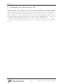
2.1
EC301 basics
Software
The EC301 is intended to operate with the SRSLab Windows software package. SRSLab can be downloaded
from the SRS web site, www.thinkSRS.com. Complete instructions for SRSLab, in the form of documentation
videos, are also available on the website.
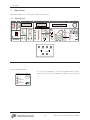
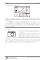
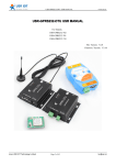
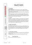
2.2
Functional block diagram
Figure 1 illustrates the major signal paths in the EC301.
17
EC301 Potentiostat/Galvanostat/ZRA
Potentiostat mode
Program E/I
output
−1
CE/3
output
+1
3
Galvanostat mode
Program
ADC
Internal scan
generation
Program E/I
measurement
CE ADC
Local feedback /
bandwidth control
Potentiostat mode
External
input
CE voltage
measurement
Compliance
limits
CE
Σ
Σ
Error
amplifier
−1
Voltage
clamp
Potentiostat,
galvanostat,
or ZRA mode
Galvanostat mode
Power
amplifier
Cell
Front panel
safety switch
Current interrupt
cell switch
CE sense
Difference
amplifiers
RE
Positive
feedback
level
WE sense
WE
Anti−alias
Voltage
measurement
10 Hz
lowpass
Current
to
voltage
Bias rejection
E output
(front panel)
E ADC
Σ
10 Hz
lowpass
Raw E output
(rear panel)
Anti−alias
Current
measurement
10 Hz
lowpass
Bias rejection
I output
(front panel)
I ADC
Σ
10 Hz
lowpass
Raw I output
(rear panel)
Figure 1: EC301 block diagram.
2
EC301 basics
2.3
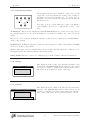
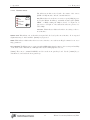
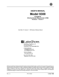
2.3 Polarity convention
Polarity convention
The relative polarity of voltages and currents handled by the EC301 follows the American polarity convention.
As illustrated in Fig. 2, this convention calls for cathodic (reducing) currents to be taken as positive. Voltages
are programmed taking RE as the reference potential, so asking for +1V with the external input or the front
panel will move the WE potential +1V above RE. We invert the polarity of the front and rear panel VOLTAGE
outputs relative to the front panel display in order to accommodate frequency response analyzers (FRAs).
Voltages and currents for 1 ohm resistive cell with
CE connected to RE
BNC outputs
Front panel displays
0V
V
Potentiostat mode
V
−1V
VOLTAGE
More anodic (oxidizing)
A
0A
+1V
WE
−1A
CURRENT
OV
External
input BNC
RE
Oxidation (anodic) current
has negative sign
0V
−1/3V
CE/3
+1V
V
More cathodic (reducing)
VOLTAGE
Galvanostat mode
0V
V RE
+1A
A
+1V
WE
OV
External
input BNC
CURRENT 0A
Reduction (cathodic) current
has positive sign
+1/3V
CE/3
0V
Figure 2: The EC301 uses the American polarity convention when applying voltages and currents.
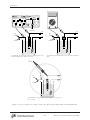
2.4
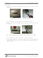
Connecting the EC19 to the EC301
Before you do any electrochemical measurements with the EC301, you must first connect the EC19.
2.4.1
Necessary Items
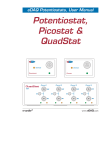
In order to connect an EC19 to an EC301, you will need a flat blade screwdriver, and the umbilical cable.
All items except the flat bladed screwdriver were provided in your EC301 shipment. Each item is pictured
in Fig. 3.
Figure 3: From left to right: EC19, umbilical cable, EC301, flat blade screwdriver.
19
EC301 Potentiostat/Galvanostat/ZRA
2
EC301 basics
2.4.2
2.4 Connecting the EC19 to the EC301
Steps
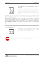
1. Identify the connection points on the EC19. There are two jack screws on the rear panel of the unit,
shown in Fig. 4.
Figure 4: EC19 rear panel connector. Securing the umbilical cable.
2. Screw the umbilical cable screws into the jack screws of the EC19 as shown in Fig. 4.
3. Identify the connection points on the EC301. There are two jack screws on the front panel of the unit,
shown in Fig. 5.
Figure 5: Front panel umbilical connector on EC301. Securing the umbilical cable to the EC301.
4. Screw the umbilical cable screws into the jack screws of the EC301 as shown in Fig. 5.
5. Power up the EC301 (switch is on rear panel). If you get any front panel errors about the EC19, turn
off the EC301. Check the umbilical connection on both ends and power up the EC301 again. If errors
persist, contact SRS.
20
EC301 Potentiostat/Galvanostat/ZRA
3
Operation
3
Operation
This manual will refer to a key with brackets such as [Key].
3.1
Front panel
BANDWIDTH LIMIT
OVERLOAD
VOLTAGE
CE LIMIT
CURRENT
EC301 POTENTIOSTAT / GALVANOSTAT / ZRA
OVERLOAD
1 MHz
100 kHz
ENABLE
TRACKING
A
mA
µA
nA
V
10 kHz
1 kHz
STANFORD RESEARCH SYSTEMS
SET LIMIT
100 Hz
ANALOG OUTPUT
MODE
10 Hz
LIMITING
CURRENT RANGE
IR COMPENSATION
POTENTIOSTAT
GALVANOSTAT
1A
CELL
BIAS
REJECTION
ZRA
ENABLE
CALIBRATE
AUTO
RANGE
CV
1 mA
10 Hz
LOW PASS
FILTER
E 1 I1
LSV
MODE
ROTATING ELECTRODE
VOLTAGE
30V/1A MAX COMPLIANCE
CURRENT
T2
SET
STEP
100 µΑ
SCAN
ENDS AT
SET
T1
GO/ARM
1 µΑ
PAUSE
SRQ
50 Ω OUTPUTS
10 k Ω
LOAD WITH
1 nA
CE
3.1.1
LOCAL
ACTIVITY
EXTERNAL
+ 15 V POTENTIOSTAT
+ 2 V GALVANOSTAT
10 nA
0−10V
REMOTE STATUS
CONTINUOUS
SCAN
TYPE
100 nA
SET
DISPLAY
ENTER
RATE
E1 /I1
TIMED
HOLD
DIRECT
CONTROL
ADD TO
SCAN
TCP/IP
GPIB
SINGLE
EXTERNAL INPUT
HOLD
10 µΑ
OPEN CIRCUIT
E2 /I2
FEEDBACK
ENABLE
100 mA
10 mA
MODE
CONFIGURE
MEASUREMENT SETUP / CONTROL
INTERRUPT
10 kΩ
REMOTE MODE
MANUAL
MODE
ADVANCE
ERROR
STOP
TRIGGER
50 pF
CE
SENSE
RE
WE
SIGNAL
GROUND
EXT TIMEBASE
WE
SENSE
Power-on reset
REMOTE STATUS
SRQ
LOCAL
To restore the instrument to its factory-default settings from the
front panel, hold down the [LOCAL] key while the power is turned
on.
ACTIVITY
REMOTE MODE
ERROR
EXT TIMEBASE
21
EC301 Potentiostat/Galvanostat/ZRA
3
Operation
3.1.2
3.1 Front panel
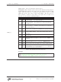
Bandwidth limit
BANDWIDTH LIMIT
Use the [∧] and [∨] keys to increase or decrease the control bandwidth.
1 MHz
100 kHz
10 kHz
1 kHz
100 Hz
10 Hz
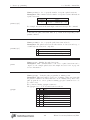
3.1.3
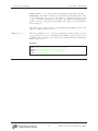
CE limit
CE LIMIT
ENABLE
SET LIMIT
The counter electrode (CE) voltage relative to ground can be limited to protect sensitive cells. Using the [ENABLE] key to enter
the limiting mode allows reducing the maximum CE voltage from
±500mV to ±30 V. This maximum is adjusted by pressing the [SET
LIMIT] key and turning the knob. The tracking light will indicate
that the CE limit follows the knob movement.
LIMITING
3.1.4
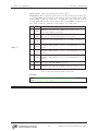
Cell
CELL
ENABLE
30V/1A MAX COMPLIANCE
The external electrometer should be connected to the main box
using this DB-25 connector. The umbilical should be securely fastened to this connector using the jack screws on either side.
Use the [ENABLE] switch to manually disconnect the CE from
the power amplifier whenever you must come in contact with the
cell electrodes. This switch is illuminated when the CE is connected
to the control circuitry. When this switch is “in,” the instrument
connects or disconnects the CE as needed. When “out,” the CE is
always disconnected and the switch is dark.
22
EC301 Potentiostat/Galvanostat/ZRA
3
Operation
3.1.5
3.1 Front panel
External electrometer
CE
CE
SENSE
RE
WE
SIGNAL
GROUND
The external electrometer face contains the counter electrode (CE)
output, three electrometer inputs, the working electrode (WE) current input, and a grounded binding post. See section 4 for illustrations of how these inputs and outputs are used in different
instrument modes.
WE
SENSE
CE (counter electrode) output: This is the output of the EC301’s
control amplifier. It can source or sink 1A into a -30V to +30V
range.
CE SENSE input: This electrometer input is used with WE SENSE in ZRA mode to monitor the voltage between
two typically identical electrodes. As shown in figure 12, it is named for usually being connected to the CE
output.
RE (reference electrode) input: As illustrated in figure 1, this electrometer input is used with WE SENSE to
monitor cell potentials.
WE SENSE input: As illustrated in figure 1, this electrometer input is used with both the RE and CE SENSE
electrodes to monitor cell potentials.
WE input: This input connects to a shunt resistor used to measure current flowing in the working electrode.
The input resistance here will vary with the current range setting.
SIGNAL GROUND: This can be connected to a Faraday cage to isolate sensitive cells from electrical noise.
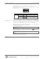
3.1.6
Voltage
VOLTAGE
This display shows the results of the internal VWE SENSE − VRE
measurement. The OVERLOAD light indicates when the cell potential
exceeds ±15 V relative to signal ground. Measurement accuracy
will degrade from specifications outside of this range.
OVERLOAD
V
3.1.7
Current
CURRENT
OVERLOAD
A
mA
µA
nA
This display shows the results of the internal cell current measurement. The OVERLOAD light indicates when current exceeds
±2×Irange or 1A, where Irange is the current range in use. Measurement accuracy will degrade from specifications during overloads.
23
EC301 Potentiostat/Galvanostat/ZRA
3
Operation
3.1.8
3.1 Front panel
Mode
Use the [MODE] key to cycle the EC301 through its various operating modes.
MODE
POTENTIOSTAT
GALVANOSTAT
ZRA
CALIBRATE
MODE
POTENTIOSTAT: control potential and measure current. In this
mode, the EC301 controls the potential of the working relative to
the reference electrode. The counter electrode is driven to whatever
potential is necessary (within the ±30 V or the user-imposed compliance limits) to hold VWE SENSE − VRE at the control (program)
voltage.
GALVANOSTAT: control current and measure potential. In this mode, the EC301 controls cell current flowing
through the working electrode. The counter electrode is driven to whatever potential is necessary to hold
this current at the programmed value.
ZRA (Zero-resistance ammeter): hold two electrodes at the same potential. In this mode, the EC301 holds
the counter and working electrodes at the same potential while current flows between them. Current flow
with no potential drop implies no resistance – hence the name of the mode. The relative potential is sensed
with the WE SENSE and CE SENSE connections, and the counter electrode is driven to hold this potential at
zero.
CALIBRATE: This function is reserved for use by the factory.
3.1.9
Rotating electrode
ROTATING ELECTRODE
This DC voltage output can be used with an external control unit
to control the speed of rotating working electrodes. Use the [SET]
key to adjust the output voltage within 0 → 10V.
SET
0−10V
This output can source a maximum of 10 mA. The input impedance of the external control
unit must be larger than 1 kΩ to achieve the maximum 10 V output.
24
EC301 Potentiostat/Galvanostat/ZRA
3
Operation
3.1.10
3.1 Front panel
Analog output
ANALOG OUTPUT
BIAS
REJECTION
10 Hz
LOW PASS
FILTER
This section contains the VOLTAGE and CURRENT analog outputs
as well as the [BIAS REJECTION] and [10 Hz LOWPASS FILTER]
controls for modifying the outputs.
VOLTAGE output (EBNC ): This output is the potential of the reference electrode with respect to the working electrode, optionally
subjected to a 10 Hz lowpass filter and/or bias rejection. The ±15
V output range is the same as the maximum polarization range.
CURRENT output (IBNC ): This output is proportional to current
flowing in the working electrode (IWE ), optionally subjected to a
10 Hz lowpass filter and/or bias rejection. The output voltage is
50 Ω OUTPUTS
given by
LOAD WITH 10 kΩ
IWE
IBNC = 1V ×
Irange
where Irange is the current range in use (1 mA, 10 mA, etc.). As described in section 2.3, IBNC becomes
more positive when current flows into the working electrode (cathodic current).
VOLTAGE
CURRENT
The polarity at the VOLTAGE BNC output (EBNC ) is opposite that reported on the front
panel displays. The voltage is thus EBNC = VRE − VWE SENSE . We invert the polarity here
to correct the sign of the cell impedance Zcell calculated with
Zcell =
EBNC
Irange × IBNC
where Irange is the current range in use and IBNC is the voltage at the CURRENT BNC output.
See figure 2 for an illustration of BNC versus display polarities.
[BIAS REJECTION]: Bias rejection attempts to subtract off the DC component of the analog output voltages.
This can be useful when making AC response measurements in the presence of a DC hold. Removing the DC
component of a signal can allow the use of more sensitive input ranges on external equipment like frequency
response analyzers.
When [BIAS REJECTION] is pushed, the EC301 will immediately average VRE − VWE SENSE and IWE
over a 1s window. It will then subtract those average values from all subsequent front panel EBNC and IBNC
outputs. The averages will not update until bias rejection is turned off and then back on. Note that the RAW
E and RAW I outputs on the rear panel always provide the VRE − VWE SENSE and IWE measurements with
no filtering or bias rejection.
Bias rejection affects both analog outputs simultaneously when engaged from the front panel,
but can be limited to either output when set up using the remote interface. The individual
rejection levels can also be set arbitrarily instead of being automatically detected. See section
7.3.8 on page 75 for the appropriate remote commands.
Neither changing the current range nor enabling autoranging is allowed while bias rejection
is active.
25
EC301 Potentiostat/Galvanostat/ZRA
3
Operation
3.1 Front panel
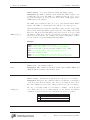
[10 Hz LOW PASS FILTER]: Use this key to simultaneously filter both the VOLTAGE and CURRENT analog
outputs. The front panel filter has a 6 dB/octave rolloff with a -3 dB frequency of 10 Hz.
You can customize filter settings using the lpfili and lpfile commands described in
section 7.3.8. These commands allow filtering a single output instead of both. Note that the
[10 Hz LOW PASS FILTER] key will light whenever filtering is applied to either output.
3.1.11
Current range
CURRENT RANGE
1A
AUTO
RANGE
100 mA
10 mA
1 mA
100 µΑ
10 µΑ
1 µΑ
100 nA
10 nA
1 nA
Use the [∧] and [∨] keys to select a current range. A cell current
(IWE ) equal to the selected current range (IWE = Irange ) gives 1 V
at the CURRENT output BNC (IBNC = 1 V). Likewise, 1 V applied
to the EXTERNAL INPUT BNC in galvanostat mode will generate a
controlled current of Irange .
Currents exceeding ±2×Irange or ±1 A will generate an overload
condition. While the EC301 can accept currents ≤ ±1 A in any
range without damage, measurement accuracy is degraded during
overloads.
Use the [AUTO RANGE] key to toggle automatic selection of
Irange based on the measured cell current. Note that auto-ranging
is not allowed in galvanostat mode.
26
EC301 Potentiostat/Galvanostat/ZRA
3
Operation
3.1.12
3.1 Front panel
IR compensation
IR compensation involves adding an “extra” voltage to the control
(program) voltage to compensate for drops between RE and WE.
Use the [MODE] key to toggle between two ways of generating this
voltage: positive feedback and current interrupt. Compensation
will not be applied until the [ENABLE] key is pressed.
IR COMPENSATION
INTERRUPT
FEEDBACK
ENABLE
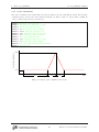
INTERRUPT mode: Figure 6 illustrates the parameters used for current interrupt when engaged from the front panel. In this mode,
the CE is periodically disconnected from the control electronics to
interrupt the cell current. This removes any IR drop between the
reference and working electrodes, causing |VWE SENSE − VRE | to
drop by ∆Vir . The EC301 then takes two samples of |VWE SENSE − VRE | to measure this drop – one after
interruption, and one after control is restored. This value, along with the percent correction factor, is used
to calculate the boost potential ∆Vb added to the program voltage.
MODE
SET
Second interruption cycle
V WE SENSE − VRE
tp
<10 µs
topen
∆ Vb
tdc
tdo
∆ V ir
Time
Figure 6: Cell potentials during current interrupt IR compensation. Default values for the various parameters
are shown in table 1.
Use the [SET] key in INTERRUPT mode to adjust the percent correction factor – the only parameter than
can be set from the front panel. The other parameters shown in figure 6 are set to the default values shown
in table 1.
Parameter
tp
topen
tdo
tdc
Default value
100 ms (10 Hz)
200µs
120µs
200µs
Remote command
ciperd (see page 72)
ciopen (see page 71)
cidlay (see page 72)
Table 1: Default values for current interrupt parameters. These values are used when current interrupt is
engaged using the front panel.
27
EC301 Potentiostat/Galvanostat/ZRA
3
Operation
3.1 Front panel
The current interrupt parameters can be adjusted away from their default values using the
remote interface. See section 7.4.3 on page 119 for an example.
FEEDBACK mode: Positive feedback IR compensation adds a boost voltage IWE × Ru to the program voltage,
where Ru is the uncompensated resistance parameter.
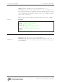
Use the [SET] key in FEEDBACK mode to adjust Ru . The allowed ranges for Ru in each current range are
shown in table 2.
Irange
1A
100 mA
10 mA
1 mA
100 µA
10 µA
1 µA
100 nA
10 nA
1 nA
Ru
0→3Ω
0 → 30 Ω
0 → 300 Ω
0 → 3 kΩ
0 → 30 kΩ
0 → 300 kΩ
0 → 3 MΩ
0 → 30 MΩ
0 → 300 MΩ
0 → 3 GΩ
Table 2: Allowed Ru ranges for each current range.
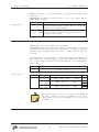
3.1.13
External input
EXTERNAL INPUT
DIRECT
CONTROL
ADD TO
SCAN
+ 15 V POTENTIOSTAT
+ 2 V GALVANOSTAT
10 kΩ
50 pF
The EC301 can take its control voltage directly from the external
analog input, allowing its use with function generators and frequency response analyzers. These control voltages can be used by
themselves or added to internally-generated scans.
In potentiostat mode, voltages applied at the external input
will be applied to the cell according to the American Polarity Convention described in section 2.3. This input has unity gain: +1 V
applied at the input will change (VWE SENSE − VRE ) by +1 V. The
input thus accepts the full ±15 V allowed polarization range.
In galvanostat mode, controlled current is given by
Vext + Vprog
IWE = Irange
1V
where Vext is the voltage applied at the external input and Vprog is the internally-generated program voltage.
Currents greater than 2 × Irange or 1 A will generate overloads, so the external input’s range in this mode is
±2 V for Irange < 1 A, and ±1 V for Irange = 1 A. The polarity is again taken from the American Polarity
Convention described in section 2.3.
Use the [ADD TO SCAN] key to toggle adding the external input voltage to internally-generated scans or
holds. This key leaves engaging the control loop (lighting the CELL button) up to the scan controls.
Use the [DIRECT CONTROL] key if potentials or currents to be applied to the cell come only from the
external input. If the cell is enabled (via the CELL button), [DIRECT CONTROL] engages or disengages the
control loop, taking control voltages or currents solely from the external input.
The external input is ignored (taken as 0 V) if both the [ADD TO SCAN] and [DIRECT CONTROL] lights
are dark.
28
EC301 Potentiostat/Galvanostat/ZRA
3
Operation
3.1.14
3.1 Front panel
Measurement setup/control
MEASUREMENT SETUP / CONTROL
CV
OPEN CIRCUIT
E 2 / I2
LSV
E 1 I1
T2
STEP
SCAN
ENDS AT
RATE
SINGLE
HOLD E 1 / I 1
SET
T1
TIMED
HOLD
GO/ARM
PAUSE
CONTINUOUS
SCAN
TYPE
EXTERNAL
MANUAL
MODE
ADVANCE
STOP
TRIGGER
A variety of automatic scans and holds can be programmed from the EC301’s front panel. Once the scan
type is selected, you will be prompted for a set of necessary parameters. When [GO/ARM] is pressed with
a MANUAL trigger setting, the EC301 will engage control, apply the scan, and remove control as required by
the scan end condition.
Use the [MODE] key to select a scan type. These types are described in section 5 on page 50.
Use the [TRIGGER] key to select the action of [GO/ARM]. In MANUAL mode, the programmed scan will
begin when [GO/ARM] is pressed. In EXTERNAL mode, pressing [GO/ARM] will “arm” the EC301 – preparing
it to scan with the next rising or falling edge received at the rear panel SCAN TRIGGER input. This allows
the scan to be triggered by other experimental events. See section 3.2.6 on page 34 for more information
about the SCAN TRIGGER input.
3.1.15
Knob
Use the knob to enter numbers via the character display. The knob
is velocity-sensitive, so experiment with different rotation speeds to
TRACKING
set large numbers.
The TRACKING indicator will light when turning the knob will
immediately affect cell conditions. For example, if a hold has been
engaged from the front panel (control loop is engaged – big red
CELL button is lit) and the [SET] key is pressed to adjust E1 /I1 ,
TRACKING will light to indicate that cell polarization is moving with
the knob. This allows manually adjusting polarization while observing other cell characteristics – “thumbwheel scanning.”
Most parameters can be “locked in” by re-pushing the same key used to set them. For example, pushing
[SET] once to adjust the E1 of a hold will allow will allow E1 to be freely changed with the knob. Pushing
[SET] again will lock the value in and disable the knob. The value will also be locked in if a [SET] key from
another section is pressed. In general, moving on to another setting will lock the previous one.
29
EC301 Potentiostat/Galvanostat/ZRA
3
Operation
3.1.16
3.1 Front panel
Configure
Use this section to configure the remote interface (LAN, GPIB)
and to cycle through the various display modes.
CONFIGURE
GPIB
TCP/IP
DISPLAY
ENTER
30
EC301 Potentiostat/Galvanostat/ZRA
3
Operation
3.1.17
3.1 Front panel
Remote status
The indicators in this section describe the status of the remote
(GPIB or LAN) interface and the external timebase.
REMOTE STATUS
SRQ
ACTIVITY
REMOTE MODE
ERROR
EXT TIMEBASE
LOCAL
SRQ: This indicator is on whenever a service request (SRQ) is generated by the EC301. It will stay on until the status register (INSR,
MESR, or *ESR) causing the SRQ is cleared. See figure 29 on
page 99 for a description of how status bit values are promoted to
cause SRQs.
ACTIVITY: This indicator flashes when there is activity on the remote interface.
REMOTE MODE: This indicator is on when the front panel is locked out by the remote interface. No front panel
adjustments may be made until the [LOCAL] key is pressed.
ERROR: This indicator flashes when there is a remote interface error such as an illegal command or an out of
range parameter.
EXT TIMEBASE: The EC301 can accept an external 10 MHz timing signal to improve the accuracy and stability
of automatic scans. This indicator will light when such a timing signal is detected.
[LOCAL]: The remote command LOCKFP can lock out the front panel keyboard. Use the [LOCAL] key to
exit this mode and enable the front panel keys.
31
EC301 Potentiostat/Galvanostat/ZRA
3
Operation
3.2
3.2
Rear panel
Rear panel
IEEE 488
INTERFACE
ETHERNET
INTERFACE
10MHz TIMEBASE
SCAN
TRIGGER
OUTPUT
INPUT
OUTPUT
RAW E
RAW I
CE / 3
SYNC ADC
OUTPUT
OUTPUT
OUTPUT
INPUT
SCAN
SYNC
PROGRAM
E/I
ADC 1
ADC 2
ADC 3
OUTPUT
INPUT
INPUT
INPUT
RTD INPUT
AC POWER
DRIVE −
DRIVE +
GROUND
SENSE −
SENSE +
INPUT
CI
SYNC
CHASSIS
GROUND
SIGNAL
GROUND
STANFORD RESEARCH SYSTEMS
3.2.1
MADE IN U.S.A.
FLOATING
GROUND
90 VAC to 260 VAC
47 Hz to 63 Hz
Power entry
AC POWER
The power entry module is used to fuse the AC line voltage input and to block high frequency noise from entering or exiting the
instrument.
90 VAC to 260 VAC
47 Hz to 63 Hz
3.2.2
GPIB interface
IEEE 488
INTERFACE
The 24 pin GPIB connector allows a computer to control the EC301
via the GPIB (IEEE-488) instrument bus. The GPIB address is
set with the front panel [GPIB] key.
32
EC301 Potentiostat/Galvanostat/ZRA
3
Operation
3.2.3
3.2
Ethernet interface
ETHERNET
INTERFACE
3.2.4
Rear panel
There are two LEDs on the RJ-45 ethernet connector. The green
LED lights only when the system is transmitting. The yellow LED
lights whenever it sees any packet on the wire. This includes packets not destined for the EC301.
Current interrupt synchronization
This digital output allows triggering an oscilloscope or other data
acquisition at the beginning of current interruption. This output
will be brought low before just before interruption begins and returned high after it ends. The timing diagram is shown in figure
7.
CI
SYNC
OUTPUT
high
CI
SYNC
low
closed
CE
switch
< 1µs
< 1µs
open
interruption
begins
interruption
ends
Time
Figure 7: Timing diagram for the CI SYNC digital output.
3.2.5
Timebase synchronization input
This BNC can accept a 10 MHz reference signal from an external source to improve the stability of the
internal clock. The external source should be greater than 1V peak-to-peak and should be within ±2 ppm
of 10 MHz.
10MHz TIMEBASE
INPUT
33
EC301 Potentiostat/Galvanostat/ZRA
3
Operation
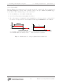
3.2.6
3.2
Rear panel
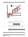
Scan trigger input
This input allows starting an automatic scan with external equipment. As illustrated in figure 8, an falling edge here will begin the
scan within 1µs.
The EC301 must be “armed” from the front panel or the remote
interface to use this input. See section 3.1.14 on page 29 to set this
condition from the front panel. See the trgarm command described
on page 73 to arm with the remote interface.
SCAN
TRIGGER
INPUT
Falling edge
starts scan
Scan
trigger
< 1µs
Program
E/I
Scan
sync
Additional edges ignored
until the EC301 is rearmed
T1
T2
< 1µs
Scan begins with
T1 delay
(a) Single scan
Falling edge
starts scan
Scan
trigger
Additional edges ignored
until the EC301 is rearmed
< 1µs
Program
E/I
T1
T2
10 µs
Scan
sync
< 1µs
Falling edge output
every time scan is
repeated
Scan begins with
T1 delay
(b) Continuous scan
Figure 8: Timing diagrams for the SCAN TRIGGER input and the SCAN SYNC output using falling edge trigger
polarity.
34
EC301 Potentiostat/Galvanostat/ZRA
3
Operation
3.2
Rear panel
Why do these scans have flat “tops?” Figure 8 illustrates both CV and LSV scans triggered
by the rear panel scan trigger input. Since the OPEN CIRCUIT end condition isn’t allowed
for this trigger mode, LSV scans must track back to their initial state after T2 – making
them look like CV scans with flat tops. The two scans would look identical for T2 = 0.
35
EC301 Potentiostat/Galvanostat/ZRA
3
Operation
3.2.7
3.2
Rear panel
Program E/I output
PROGRAM
E/I
OUTPUT
This output is a copy of the input to the EC301’s control circuitry.
As illustrated in figure 1, it is the sum of the external input and
the internal scan voltages.
When used with current interrupt IR compensation, this output
provides the “corrected” potential applied to the working electrode.
It can be used to plot IR-compensated data on xy plotters and
displays.
This output will reflect the input to the EC301’s control circuitry even when the control
loop is open. For example, starting a +1V hold from the front panel (without any external
input voltage) will move PROGRAM E/I to −1V. Stopping the hold won’t change this output
– it will remain at −1V until a new scan is configured and run. Note that the polarity for
this output is consistent with the front-panel VOLTAGE output described in section 2.3 on
page 19.
36
EC301 Potentiostat/Galvanostat/ZRA
3
Operation
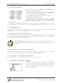
3.2.8
3.2
Rear panel
Scan synchronization output
This output allows triggering an oscilloscope or synchronizing other
data acquisition using with the start of a scan. As illustrated in
figure 9, this output is brought low immediately before the scan
begins and before every scan repetition during continuous scans.
The output is held low for 10 µs before returning high, which limits
the rate to roughly 50 kHz. The EC301 can not reliably send trigger
pulses for repetition rates faster than this.
SCAN
SYNC
OUTPUT
10 µs
High
Scan sync
output
< 1µs
Low
Program
E/I
Time
Figure 9: The SCAN SYNC output is brought low at the beginning of a scan and held there for 10 µs.
37
EC301 Potentiostat/Galvanostat/ZRA
3
Operation
3.2.9
3.2
Rear panel
Auxiliary ADC inputs (1-3)
ADC 1
ADC 2
ADC 3
INPUT
INPUT
INPUT
These ±10 V inputs allow monitoring analog signals like flow rate,
pH, or temperature along with E and I data. Using the remote
interface, data from these inputs can be synchronized with E and
I collection to within 1 ms. Use the synchronous ADC input described in section 3.2.14 on page 43 for tighter timing requirements.
Use the getaux? command described on page 80 to acquire data from these BNCs using the
remote interface
38
EC301 Potentiostat/Galvanostat/ZRA
3
Operation
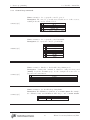
3.2.10
3.2
Rear panel
Resistance temperature detector (RTD) input
RTD INPUT
DRIVE −
DRIVE +
GROUND
SENSE −
SENSE +
The EC301 can accept standard 100Ω Pt RTD probes for logging
experimental temperatures. The probe temperature is determined
with a 4-wire measurement of the probe resistance. As illustrated
in figure 10, commercial 4-wire RTDs normally have two wires of
the same color connected to one end of the resistive sensor, and
two wires of a different color connected to the opposite end. One
of each pair carries the drive current used in the measurement, and
the other is used to sense the voltage induced by this current. The
“drive” and “sense” leads are interchangeable.
100Ω Pt RTD
Figure 10: Commercial 4-wire RTD probes have two wires with the same color attached to each end.
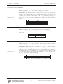
These 4-wire sensors are connected to the EC301 in one of two electrically-identical ways illustrated in
figure 11. Notice that the signs of the DRIVE and SENSE inputs match for the same color of wire. Any other
wire configuration will give no temperature reading when the probe is connected.
OR
DRIVE −
DRIVE +
GROUND
SENSE −
SENSE +
DRIVE −
DRIVE +
GROUND
SENSE −
SENSE +
Figure 11: 4-wire probes can be connected to the EC301 in one of these two ways.
RTD sensor wires are connected to the RTD input using 5-pin Weidmuller plugs (Weidmuller part number
169045). These plugs use a tension clamp to hold the wires in place. To install the wires:
1. Hold the plug in front of you with the five small holes on top and the five larger holes on the bottom.
2. In each hole is a metal clip. Place a small screwdriver into one of the small holes and firmly push it
in to the small gap above the clip. The screwdriver should go in about half an inch. The thickness of
the screwdriver shaft pushes the clip down toward the larger hole.
3. The larger hole should open up. Place a stripped wire into the hole and remove the screwdriver.
39
EC301 Potentiostat/Galvanostat/ZRA
3
Operation
3.2.11
3.2
Rear panel
Grounding posts
SIGNAL
GROUND
These grounding posts should be connected together unless the cell’s working electrode is intrinsically grounded.
Disconnecting these isolates the CE-to-WE current path from earth
ground, allowing measurements with grounded working electrodes.
See section 4.2 for more information on this situation.
FLOATING
GROUND
40
EC301 Potentiostat/Galvanostat/ZRA
3
Operation
3.2.12
3.2
Rear panel
Raw analog outputs
RAW E
RAW I
OUTPUT
OUTPUT
These outputs carry the same signals as their counterparts on the
front panel, but without any bias rejection or filtering. See section
3.1.10 for a better description of the E and I output voltages. The
same polarity convention applies to both the front and rear panel
outputs.
The output resistance of these sources is 50Ω – the same as for those on the front panel.
The input resistance of whatever these outputs are connected to should exceed 10kΩ to
keep loading errors below 1%.
41
EC301 Potentiostat/Galvanostat/ZRA
3
Operation
3.2.13
3.2
Rear panel
CE monitor
CE / 3
This output provides the counter electrode (CE) voltage relative
to floating ground divided by 3. If signal and floating grounds are
connected together, this output will span ±10 V as the CE spans
±30 V. As with the raw E and I outputs, this signal is not affected
by bias rejection or filter settings.
OUTPUT
The output resistance of this source is 50Ω. The input resistance of whatever this is
connected to should exceed 10kΩ to keep loading errors below 1%.
42
EC301 Potentiostat/Galvanostat/ZRA
3
Operation
3.2.14
3.2
Rear panel
Synchronous ADC input
SYNC ADC
This ±10 V analog input allows sampling external signals simultaneously with the E and I measurements. The EC301 has separate
ADCs devoted to the E, I, and synchronous ADC measurements.
All three ADCs share the same sample control signal to ensure
simultaneous measurements.
INPUT
43
EC301 Potentiostat/Galvanostat/ZRA
4
4
Making cell connections
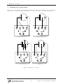
Making cell connections
Figures 12a, b, and c illustrate how the EC301 should be used with cell configurations in potentiostat and
galvanostat modes. Figure 12d illustrates typical cell connections during an experiment using ZRA mode.
WE
CE
WE
CE
RE
CE
CE
SENSE
RE
WE
SENSE
WE
SIGNAL
GROUND
CE
(a) Two-terminal cell
RE
WE
SIGNAL
GROUND
WE
WE1
WE2
RE2
RE1
CE
SENSE
RE
WE
SIGNAL
GROUND
WE
SENSE
(b) Three-terminal cell
CE
CE
CE
SENSE
RE
CE
WE
SENSE
(c) Four-terminal cell
CE
SENSE
RE
WE
SIGNAL
GROUND
WE
SENSE
(d) ZRA mode
Figure 12: Making cell connections
44
EC301 Potentiostat/Galvanostat/ZRA
4
Making cell connections
4.1 Floating operation
Probing electrode voltages with a standard oscilloscope probe can cause problems with
grounding and noise. See appendix A for more details.
4.1
Floating operation
The EC301 was designed with floating operation in mind. Users may operate on a Working Electrode
(WE) that is intrinsically grounded, or they may wish to strap the Counter Electrode (CE) to earth ground
for safety reasons. The EC301 will accommodate those measurements, but there are some configuration
adjustments that must be made.
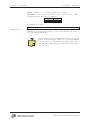
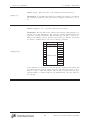
4.1.1
Overview
For floating operation, remove the factory-installed shorting bar that ties the “signal ground” and the
“floating ground” together (see Fig. 13). Pull the bar away from the instrument to remove it.
Figure 13: EC301 grounding bar (installed).
The signal ground is an internal reference which is maintained at close to chassis ground potential. The
floating ground is a separate reference that is free to reach a potential difference up to ±8 volts from signal
ground. In the event the potential between signal and floating grounds exceeds this limit, the instrument
45
EC301 Potentiostat/Galvanostat/ZRA
4
Making cell connections
4.1 Floating operation
will not be damaged. In this case, the CE limit will be activated and the potential across the cell will not
be well-controlled.
The EC301 grounding scheme leaves all the connectors on the chassis unaffected by floating operation.
Instruments such as oscilloscopes and frequency response analyzers often tie other instruments’ chassis to
earth ground once a BNC cable is attached between them. This is permissible even when the EC301 is
floating, because the BNC shells are tied to chassis ground and not floating ground. This enables EIS
(electrochemical impedance spectroscopy) even on working electrodes that must float.
Floating operation necessitates some trade-offs in performance. The EC301 specifications only apply
when the signal and floating grounds are connected on the rear panel by the supplied shorting bar (i.e. when
the instrument is not floating).
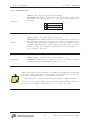
4.1.2
Grounded Working Electrode
Grounded Working Electrode Configuraon
Counter Electrode
Reference Electrode
Cell
Working sense
Electrode
Working Electrode
Shor!ng Bar
Signal Ground
Potenostac Polarizaon Range: ±15 V
Figure 14: Grounded working electrode configuration.
Once you have removed the shorting bar from the rear panel of the instrument (see Overview, above),
install it between the two banana jacks on the EC19 labeled “WE” and “SIGNAL GROUND” (see Fig. 15).
The shorting bar provides a low impedance path between the intrinsic ground at the cell and the EC301
internal reference ground, improving noise performance and adding stability to the current meter.
Make the rest of the connections from the EC19 to the cell as normal. Under these conditions, the full
±15 V potentiostatic polarization range is available.
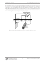
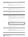
4.1.3
Grounded Counter Electrode
Once you have removed the shorting bar from the rear panel of the instrument (see Overview, above), you are
ready to begin measurements in this configuration. You may achieve somewhat improved noise performance
by attaching a jumper between CE and signal ground.
When you tie the CE to Earth ground, be aware that the full potentiostatic polarization range is not
available. In this configuration, the potentiostatic set point dictates the potential between signal and floating
ground. The maximum polarization range under these conditions is ±8 V.
46
EC301 Potentiostat/Galvanostat/ZRA
4
Making cell connections
4.2
Working with grounded electrodes
Figure 15: Grounding WE at the EC19.
Grounded Counter Electrode Configura"on
Example: Grounded Metal Vessel used as Counter Electrode
Counter Electrode
Reference Electrode
Working sense
Electrode
Working Electrode
O
P
T
I
O
N
A
L
Cell
J
U
M
P
E
R
Signal Ground
Poten"osta"c Polariza"on Range: ±8 V
Figure 16: Grounded counter electrode configuration.
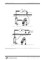
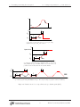
4.2
Working with grounded electrodes
Grounded electrodes are those inextricably connected to earth ground. Figure 17 illustrates cathodic protection of a buried pipeline, in which the counter and working electrodes are necessarily buried in and thus
connected to earth. Figure 18a illustrates the proper current circuit in this situation: out of the power amplifier, through the CE and WE electrodes, through the WE shunt resistor, and back to the power amplifier
47
EC301 Potentiostat/Galvanostat/ZRA
4
Making cell connections
4.2
Working with grounded electrodes
through floating ground. If, however, the floating and signal ground binding posts described in section 3.2.11
are left connected, current can bypass the WE entirely. Figure 18b shows current flowing out of the CE and
being returned to the power amplifier through earth ground, which has a low-resistance connection to signal
ground. The rear panel signal and floating grounds should thus be disconnected when making measurements
with grounded electrodes.
The rear panel ground banana jacks should only be disconnected when necessary. Reconnect
them when using isolated cells to improve frequency response.
CE
CE
SENSE
RE
WE
SIGNAL
GROUND
WE
SENSE
Soil surface
Anode
Cathode
(buried pipe)
Figure 17: Buried and inextricably grounded electrodes used in cathodic protection.
48
EC301 Potentiostat/Galvanostat/ZRA
4
Making cell connections
4.2
Working with grounded electrodes
V
Floating ground
Soil surface
CE
WE
Current flow
Earth
ground
WE
shunt
resistor
(a) Proper current flow with floating and signal ground posts disconnected
V
Floating
ground
Soil surface
Signal ground
connected to
earth ground
Earth
ground
(b) One of many undesired current flow paths with floating and signal ground posts
connected
Figure 18: Disconnecting the signal and floating ground terminals on the EC301 allows current to flow in
circuits including earth ground.
49
EC301 Potentiostat/Galvanostat/ZRA
5
Performing scans using the front panel
5
Performing scans using the front panel
5.1
5.1.1
Setting scan parameters – potentiostat mode
Cyclic voltammetry (CV)
Figure 19 illustrates the parameters needed to specify a CV scan. The procedure is as follows:
1. Use the [MODE] key to select CV.
2. Cycle through the required parameters using [SET], adjusting values using the knob. Times are
adjusted using the knob for individual fields, and the arrow keys described in section 3.1.16 on page
30 to move between the fields shown below.
00 :
00 : |{z}
00 : |{z}
|{z}
hours
minutes
seconds
{z }
|0000
seconds/104
The maximum hold time for a CV is 99:59:59.9999 (100 µs short of 100 hours). The setability is in
100 µs steps.
3. Choose the scan end condition. Figure 19(a) illustrates the cell potential for the E1 end condition,
while 19(b) shows it for OPEN CIRCUIT.
4. Choose SINGLE or CONTINUOUS scanning. Single scans, illustrated in figures 19(a) and (b), go to the
end scan condition after reaching E1 on the return ramp. Continuous scans, illustrated in figure 19(c),
immediately turn around to repeat the forward ramp and then the entire triangle-shaped waveform.
5. Choose the trigger mode. MANUAL allows the [GO/ARM] key to trigger the scan, while EXTERNAL mode
requires the rear panel scan trigger input. See section 5.4 on page 61 for a better description of scan
triggers in general, and section 3.2.6 on page 34 for a description of the rear panel scan trigger.
50
EC301 Potentiostat/Galvanostat/ZRA
5
Performing scans using the front panel
5.1 Setting scan parameters – potentiostat mode
I
E1
E2
E
E
E2
T1
E1
Rate
Time
(a) A CV program and typical I vs. E plot using SINGLE
scan type and E1 end condition.
E
Open circuit
E2
T1
E1
Rate
Time
(b) A CV program followed by a simulated jump to open circuit
using SINGLE scan type and OPEN CIRCUIT end condition. The cell
potential is uncontrolled when the return ramp finishes.
E
E2
T1
E1
Rate
Time
(c) A CV program using CONTINUOUS scan type. The triangle-shaped program continues
indefinitely.
Figure 19: Parameters used to set up a cyclic voltammogram (CV).
51
EC301 Potentiostat/Galvanostat/ZRA
5
Performing scans using the front panel
5.1.2
5.1 Setting scan parameters – potentiostat mode
Linear sweep voltammetry (LSV)
Figure 20 illustrates the parameters needed to specify a LSV scan. The procedure is as follows:
1. Use the [MODE] key to select LSV.
2. Cycle through the required parameters using [SET], adjusting values using the knob. Times are
adjusted using the knob for individual fields, and the arrow keys described in section 3.1.16 on page
30 to move between the fields shown below.
00 : |{z}
00 : |{z}
00 :
|{z}
hours
minutes
seconds
{z }
|0000
seconds/104
The maximum hold time for a LSV is 99:59:59.9999 (100 µs short of 100 hours). The setability is in
100 µs steps.
3. Choose the scan end condition. Figure 20(a) illustrates the cell potential for the E1 end condition,
while 20(b) shows it for OPEN CIRCUIT. If the end condition is OPEN CIRCUIT, the cell potential will
be free to drift after the T2 wait time. If the condition is E1 , the potential will immediately return to
E1 .
4. Choose SINGLE or CONTINUOUS scanning. Single scans, illustrated in figures 20(a) and (b), go to the
end scan condition after the T2 wait time. Continuous scans, illustrated in figure 20(c), track back to
E1 after the T2 wait time with the same rate used for the forward ramp. They then repeat the entire
program indefinitely.
5. Choose the trigger mode. MANUAL allows the [GO/ARM] key to trigger the scan, while EXTERNAL mode
requires the rear panel scan trigger input. See section 5.4 on page 61 for a better description of scan
triggers in general, and section 3.2.6 on page 34 for a description of the rear panel scan trigger.
52
EC301 Potentiostat/Galvanostat/ZRA
5
Performing scans using the front panel
5.1 Setting scan parameters – potentiostat mode
I
E1
E2
E
T2
E
E2
T1
Rate
E1
Time
(a) A LSV program and typical I vs. E plot using
SINGLE scan type and E1 end condition.
E
Open circuit
T2
E2
T1
E1
Rate
Time
(b) A LSV program followed by a simulated jump to open circuit
using SINGLE scan type and OPEN CIRCUIT end condition. The cell
potential is uncontrolled when the T2 wait time finishes.
T2
E
T2
E2
T1
E1
T1
Rate
Time
(c) A LSV program using CONTINUOUS scan type. The trapezoid-shaped program continues indefinitely.
Figure 20: Parameters used to set up a linear sweep voltammogram (LSV).
53
EC301 Potentiostat/Galvanostat/ZRA
5
Performing scans using the front panel
5.1.3
5.1 Setting scan parameters – potentiostat mode
Steps
Figure 21 illustrates the parameters needed to specify a step scan. The procedure is as follows:
1. Use the [MODE] key to select STEP.
2. Cycle through the required parameters using [SET], adjusting values using the knob. Times are
adjusted using the knob for individual fields, and the arrow keys described in section 3.1.16 on page
30 to move between the fields shown below. Note that the setability is in 4µs steps.
00 :
00 : |{z}
|{z}
minutes
seconds
000
|{z}
milliseconds
: |{z}
000
µseconds
The maximum delay time is 01:07.108 860 (224 − 1 counts × 4 µs/count).
3. Setability is 4 µs.
4. Choose the scan end condition. Figure 21(a) illustrates the cell potential for the E1 end condition,
while 21(b) shows it for OPEN CIRCUIT. If the end condition is OPEN CIRCUIT, the cell potential will
be free to drift after the T2 wait time. If the condition is E1 , the potential will immediately return to
E1 .
5. Choose SINGLE or CONTINUOUS scanning. Single scans, illustrated in figures 21(a) and (b), go to the
end scan condition after the T2 wait time. Continuous scans, illustrated in figure 21(c), step back to
E1 after the T2 wait time and repeat the entire step program indefinitely.
6. Choose the trigger mode. MANUAL allows the [GO/ARM] key to trigger the scan, while EXTERNAL mode
requires the rear panel scan trigger input. See section 5.4 on page 61 for a better description of scan
triggers in general, and section 3.2.6 on page 34 for a description of the rear panel scan trigger.
54
EC301 Potentiostat/Galvanostat/ZRA
5
Performing scans using the front panel
5.1 Setting scan parameters – potentiostat mode
I
T1
Time
T2
E
Open circuit
E
E2
E2
T2
T1
T2
T1
E1
E1
T1
Time
(a) A step program and typical I vs. E plot
using SINGLE scan type and E1 end condition.
Time
(b) A step program followed by a simulated jump to
open circuit using SINGLE scan type and OPEN CIRCUIT
end condition. The cell potential is uncontrolled when
the T2 wait time finishes.
E
E2
T1
T2
T2
T1
E1
Time
(c) A step program using CONTINUOUS scan type. The rectangle-shaped
program continues indefinitely.
Figure 21: Parameters used to set up a step scan.
55
EC301 Potentiostat/Galvanostat/ZRA
5
Performing scans using the front panel
5.1.4
5.1 Setting scan parameters – potentiostat mode
Holds
Figure 22 illustrates the parameters needed to specify holds or timed holds. These scans must end in the
OPEN CIRCUIT condition, and the scan type can only be SINGLE. Only MANUAL trigger mode is allowed. The
remaining setup procedure is as follows:
1. Use the [MODE] key to select HOLD or TIMED HOLD.
2. Set the E1 and T1 parameters using [SET] and the knob.
3. Choose the trigger mode. MANUAL allows the [GO/ARM] key or the remote interface to start the hold.
See section 5.4 on page 61 for a better description of scan triggers. EXTERNAL mode is not allowed.
E
Open circuit
Indefinite
E1
Time
Scan ended manually
(a) A (indefinite) hold program.
CIRCUIT condition.
Holds must end in the OPEN
E
Open circuit
T1
E1
Time
(b) A timed hold program. Control is automatically released after
the T1 hold time.
Figure 22: Parameters used to set up a regular and timed hold.
56
EC301 Potentiostat/Galvanostat/ZRA
5
Performing scans using the front panel
5.2
5.2 Setting scan parameters – galvanostat mode
Setting scan parameters – galvanostat mode
5.2.1
Cyclic current ramp
Figure 23 illustrates the parameters needed to specify a cyclic current ramp scan. The procedure is as
follows:
1. Use the [MODE] key to select CV. While this scan mode is named for its use in potentiostat mode, it
will set up a cyclic current ramp in galvanostat mode.
2. Cycle through the required parameters using [SET], and adjust values using the knob.
3. Choose the scan end condition. Figure 23(a) illustrates the cell current for the I1 end condition, while
23(b) shows it for OPEN CIRCUIT.
4. Choose SINGLE or CONTINUOUS scanning. Single scans, illustrated in figures 23(a) and (b), go to the
end scan condition after reaching I1 on the return ramp. Continuous scans, illustrated in figure 23(c),
immediately turn around to repeat the forward ramp and then the entire triangle-shaped waveform.
5. Choose the trigger mode. MANUAL allows the [GO/ARM] key to trigger the scan, while EXTERNAL mode
requires the rear panel scan trigger input. See section 5.4 on page 61 for a better description of scan
triggers in general, and section 3.2.6 on page 34 for a description of the rear panel scan trigger.
I
I
I
I
T1
2
T1
I
2
I
Rate
1
1
Rate
0
Time
Time
(a) A cyclic current ramp program using SINGLE scan
type and I1 end condition.
(b) A cyclic current ramp program followed by a simulated jump to open circuit (zero current) using SINGLE
scan type and OPEN CIRCUIT end condition. The cell
current and potential are uncontrolled when the return
ramp finishes.
I
I
2
T1
I
1
Rate
Time
(c) A cyclic current ramp program using CONTINUOUS scan type. The triangle-shaped
program continues indefinitely.
Figure 23: Parameters used to set up a cyclic current ramp scan.
57
EC301 Potentiostat/Galvanostat/ZRA
5
Performing scans using the front panel
5.2.2
5.2 Setting scan parameters – galvanostat mode
Linear current ramp
Figure 24 illustrates the parameters needed to specify a linear current ramp scan. The procedure is as
follows:
1. Use the [MODE] key to select LSV. While this scan mode is named for its use in potentiostat mode, it
will set up a linear current ramp in galvanostat mode.
2. Cycle through the required parameters using [SET], and adjust values using the knob.
3. Choose the scan end condition. Figure 24(a) illustrates the cell potential for the I1 end condition,
while 24(b) shows it for OPEN CIRCUIT.
4. Choose SINGLE or CONTINUOUS scanning. Single scans, illustrated in figures 24(a) and (b), go to the
end scan condition after the T2 wait time. Continuous scans, illustrated in figure 24(c), track back to
I1 after the T2 wait time with the same rate used for the forward ramp. They then repeat the entire
program indefinitely.
5. Choose the trigger mode. MANUAL allows the [GO/ARM] key to trigger the scan, while EXTERNAL mode
requires the rear panel scan trigger input. See section 5.4 on page 61 for a better description of scan
triggers in general, and section 3.2.6 on page 34 for a description of the rear panel scan trigger.
I
T2
I
I
I
2
T1
2
I
T1
I
T2
Rate
1
1
Rate
0
Time
Time
(a) A linear current ramp program using SINGLE scan
type and I1 end condition.
T2
I
I
T2
2
T1
I
(b) A linear current ramp program followed by a simulated jump to open circuit (zero current) using SINGLE
scan type and OPEN CIRCUIT end condition. The cell
current and potential are uncontrolled when the return
ramp finishes.
1
T1
Rate
Time
(c) A linear current ramp program using CONTINUOUS scan type. The triangle-shaped program continues indefinitely.
Figure 24: Parameters used to set up a linear current ramp scan.
58
EC301 Potentiostat/Galvanostat/ZRA
5
Performing scans using the front panel
5.2.3
5.2 Setting scan parameters – galvanostat mode
Current step
Figure 25 illustrates the parameters needed to specify a current step scan. The procedure is as follows:
1. Use the [MODE] key to select STEP.
2. Cycle through the required parameters using [SET], and adjust values using the knob.
3. Choose the scan end condition. Figure 25(a) illustrates the cell potential for the I1 end condition,
while 25(b) shows it for OPEN CIRCUIT. If the end condition is OPEN CIRCUIT, the cell potential will be
free to drift after the T2 wait time. If the condition is I1 , the potential will immediately return to I1 .
4. Choose SINGLE or CONTINUOUS scanning. Single scans, illustrated in figures 25(a) and (b), go to the
end scan condition after the T2 wait time. Continuous scans, illustrated in figure 25(c), step back to
I1 after the T2 wait time and repeat the entire step program indefinitely.
5. Choose the trigger mode. MANUAL allows the [GO/ARM] key to trigger the scan, while EXTERNAL mode
requires the rear panel scan trigger input. See section 5.4 on page 61 for a better description of scan
triggers in general, and section 3.2.6 on page 34 for a description of the rear panel scan trigger.
I
I
I
I
T1
2
T1
I
2
T2
I
1
T2
1
0
Time
Time
(a) A current step program using SINGLE
scan type and E1 end condition.
(b) A current step program followed by a
simulated jump to open circuit using SINGLE
scan type and OPEN CIRCUIT end condition.
The cell current and potential are uncontrolled when the T2 wait time finishes.
I
I
2
T1
I
T2
T2
T1
1
Time
(c) A current step program using CONTINUOUS scan type. The rectangleshaped program continues indefinitely.
Figure 25: Parameters used to set up a step scan.
59
EC301 Potentiostat/Galvanostat/ZRA
5
Performing scans using the front panel
5.2.4
5.2 Setting scan parameters – galvanostat mode
Current hold
Figure 26 illustrates the parameters needed to specify current holds or timed holds. These scans must end
in the OPEN CIRCUIT (zero current) condition, and the scan type can only be SINGLE. Only MANUAL trigger
mode is allowed. The remaining setup procedure is as follows:
1. Use the [MODE] key to select HOLD or TIMED HOLD.
2. Set the I1 and T1 parameters using [SET] and the knob.
3. Choose the trigger mode. MANUAL allows the [GO/ARM] key or the remote interface to start the hold.
See section 5.4 on page 61 for a better description of scan triggers. EXTERNAL mode is not allowed.
I
Indefinite
I
I
T1
1
I
0
Time
Scan ended manually
1
0
Time
(a) A (indefinite) current hold program. Holds must (b) A timed current hold program. Control is automatend in the OPEN CIRCUIT (zero current) condition.
ically released after the T1 hold time.
Figure 26: Parameters used to set up a regular and timed current hold.
60
EC301 Potentiostat/Galvanostat/ZRA
5
Performing scans using the front panel
5.3
5.3 Basic scan controls
Basic scan controls
GO/ARM
PAUSE
STOP
ADVANCE
Once a scan is configured, the [GO/ARM], [PAUSE], [ADVANCE], and
[STOP] keys control how it will execute.
Pressing the [GO/ARM] key is one way to send a scan trigger
described in section 5.4. This will begin a scan in MANUAL trigger
mode, or arm the instrument in EXTERNAL mode.
The [PAUSE] key freezes the scan wherever it happens to be.
Pressing it again will resume the scan.
The [ADVANCE] key increments the scan stage. For example,
pressing this during the forward ramp of a CV scan will start the
return ramp. Pressing this during the return ramp will skip to the
end scan condition.
The [STOP] key terminates the scan and releases cell control. This does not simply take the scan to the
scan end condition – control is always released. Use the [ADVANCE] key instead to skip to the end of a scan.
5.4
Triggering scans
A configured scan will start once the EC301 receives a scan trigger. This can come from the front panel
[GO/ARM] button, the rear panel scan trigger input, or the remote interface.
5.4.1
Triggering a scan from the front panel
As described in section 3.1.14 on page 29, the front panel [GO/ARM] key will start a scan if the trigger mode
is set to MANUAL. Pressing this in the EXTERNAL trigger mode will “arm” the instrument – control will engage
but scanning will wait for the scan trigger input.
The [GO/ARM] key will try to engage cell control to begin a scan in both trigger modes –
lighting the [ENABLE] switch. Make sure to allow this by pressing this switch to the “on”
position.
5.4.2
Triggering a scan with the scan trigger input
As described in section 3.2.6 on page 34, the rear panel scan trigger input allows fine control over when the
scan begins. This can help to synchronize external data acquisition during fast scans.
5.4.3
Triggering a scan from the remote interface
The scan trigger remote commands are described in section 7.3.6 on page 73.
5.5
Setting the end of scan condition
OPEN CIRCUIT
E1 I1
The EC301 can either retain or release control of a cell at the end
of a scan. Retaining control may reduce drift in cell characteristics
between scans, while releasing control may reduce stress on the cell.
Select OPEN CIRCUIT to release control, or E1 /I1 to retain control
at the E1 or I1 setting.
SCAN
ENDS AT
61
EC301 Potentiostat/Galvanostat/ZRA
5
Performing scans using the front panel
5.5 Setting the end of scan condition
Only OPEN CIRCUIT is allowed as an end condition for HOLD or TIMED HOLD scan modes.
62
EC301 Potentiostat/Galvanostat/ZRA
6
Using the EC301 with a frequency response analyzer (FRA)
6
Using the EC301 with a frequency response analyzer (FRA)
The EC301 can be used with an FRA to perform electrochemical impedance spectroscopy (EIS) measurements. The FRA supplies the stimulus for these measurements via the external input, and measures the
cell response via the E and I outputs. Figure 27 shows the EC301 used with the Stanford Research Systems
SR780 for this purpose.
For best results, especially at high frequency, SRS recommends using the rear panel outputs for EIS
measurements.
SR780
BANDWIDTH LIMIT
OVERLOAD
VOLTAGE
CE LIMIT
CURRENT
100 kHz
ENABLE
EC301 POTENTIOSTAT / GALVANOSTAT / ZRA
OVERLOAD
1 MHz
TRACKING
A
mA
µA
nA
V
10 kHz
1 kHz
STANFORD RESEARCH SYSTEMS
SET LIMIT
100 Hz
LIMITING
CURRENT RANGE
ANALOG OUTPUT
MODE
10 Hz
IR COMPENSATION
POTENTIOSTAT
1A
AUTO
RANGE
BIAS
REJECTION
ZRA
CALIBRATE
1 mA
VOLTAGE
30V/1A MAX COMPLIANCE
E 1 I1
T2
SET
STEP
SET
TIMED
HOLD
GO/ARM
1 µΑ
CURRENT
Voltage
Source
PAUSE
REMOTE STATUS
CONTINUOUS
SCAN
TYPE
SRQ
Channel 1 Channel 2
A
B
A B
LOCAL
ACTIVITY
EXTERNAL
100 nA
SET
0−10V
DISPLAY
ENTER
RATE
E1 /I1
T1
DIRECT
CONTROL
ADD TO
SCAN
TCP/IP
GPIB
SCAN
ENDS AT
SINGLE
EXTERNAL INPUT
100 µΑ
10 µΑ
OPEN CIRCUIT
E2 /I2
LSV
MODE
HOLD
10 Hz
LOW PASS
FILTER
ROTATING ELECTRODE
CV
FEEDBACK
ENABLE
100 mA
10 mA
MODE
CONFIGURE
MEASUREMENT SETUP / CONTROL
INTERRUPT
GALVANOSTAT
CELL
ENABLE
+ 15 V POTENTIOSTAT
+ 2 V GALVANOSTAT
10 nA
1 nA
50 Ω OUTPUTS
10 kΩ
LOAD WITH
Current
10 k Ω
REMOTE MODE
MANUAL
MODE
ADVANCE
50 pF
ERROR
STOP
TRIGGER
EXT TIMEBASE
External input
Figure 27: Using the EC301 with the SR780 for impedance spectroscopy
Using the setup shown in figure 27, the SR780 supplies the stimulus for swept-sine or FFT-based measurements via the external input BNC. It then can calculate the complex cell frequency response as
FFT2
FFT1
(1)
spectrum2
spectrum1
(2)
Response =
for FFT-based measurements or as
Response =
using the swept-sine mode. The cell impedance Zcell can be calculated from this using
Zcell =
spectrum2
Ifs × spectrum1
(3)
where Ifs is the current range (10mA, 100µA, etc).
63
EC301 Potentiostat/Galvanostat/ZRA
7
Remote programming
7
Remote programming
The EC301 may be remotely programmed via either the GPIB or ethernet interfaces.
When using the ethernet interface, be advised that some “personal firewall” systems will terminate idle
connections.
7.1
Command syntax
Communication with the EC301 is done with ASCII characters. Commands may be in either UPPER or
lower case and may contain any number of embedded space characters. For example, the commands
ECMODE 1
ECMODE
1
ecmode 1
will all put the instrument in galvanostat mode.
Multiple commands may be sent on one command line by separating them with semicolons (;). The
individually-sent commands
ecmode 1
clbwth 4
irange 1
can be sent simultaneously with
ecmode 1;clbwth 4;irange 1
following which the EC301 will buffer and then execute the command string from left to right.
7.2
Argument formats
Table 3 summarizes the number formats expected for each argument designator.
Argument designators
i,j,k
x,y,z
Format
integer
real number
Good examples
-1200,0,1,5,+6
-1.34,0.0,3.14159
Unrecognized
-1.2e3,0x5
Table 3: Number formats expected for each argument designator.
Numbers written in scientific notation will not be recognized as allowed arguments.
64
EC301 Potentiostat/Galvanostat/ZRA
7
Remote programming
7.3
7.3.1
Detailed command list
Firmware and hardware revisions
fpgarv?
7.3.2
7.3 Detailed command list
Name: fpgarv? – Query the FPGA revision number.
Description: The instrument’s FPGA revision number is important for firmware
upgrades.
Program E/I setup (with external input)
Name: setvol(?) – Set or query DC bias voltage.
Description: This command provides an easy way to control a DC voltage without setting up a scan.
Parameter
i
Units
mV
Range
−15000, −14999, −14998, · · · , +15000
For example, the sequence
setvol(?){i}
ecmode 0
ceenab 1
setvol 1000
setvol?
1000
will set up a program voltage of 1V in potentiostat mode. The setvol? query
command will return a value in the same format as the setting. This command
is not allowed in galvanostat mode, zra mode, or if the unit is in direct control
mode.
65
EC301 Potentiostat/Galvanostat/ZRA
7
Remote programming
7.3 Detailed command list
Name: setcur(?) – Set or query DC bias for the current program in galvanostat
mode.
Description: This command provides an easy way to control a DC current without setting up a scan.
Parameter
x
Units
fraction of range
Range
−2 → +2
For example, the sequence
setcur(?){x}
ecmode 1
ceenab 1
irange 4
setcur 0.543
setcur?
5.43e-4
will set up a program current of 0.543mA in galvanostat mode. The argument to
setcur is the signed floating-point fraction of the current range. Since irange 4
chooses the 1mA range, an argument of 0.543 sets a control current of 0.543 ×
1mA = 543µA. The setvol? query command will return the actual setpoint in A
instead of the fraction of full scale. This command is not allowed in potentiostat
or zra mode.
Name: addscn(?) – Set or query the external input’s “add to scan” mode.
Description: This command enables or disables the external input without affecting the state of the control loop.
i
0
1
addscn(?){i}
Setting
Voltage at external input ignored
Voltage at external input added to scan or hold
This is useful for adding a waveform from an external source to a ramp generated by the EC301. For example, a sine wave could be added to a ramp for AC
voltammetry. Changing the addscn state will turn the external waveform on or off
without affecting the EC301’s waveform. If −1V is applied to the external input,
the sequence
ecmode
setvol
ceenab
addscn
0
+1000
1
1
will result in 0V over the cell.
66
EC301 Potentiostat/Galvanostat/ZRA
7
Remote programming
7.3 Detailed command list
Name: dcntrl(?) – Set or query the external input’s “direct control” mode.
Description: This command enables or disables the external input while engaging
and disengaging cell control.
i
0
1
dcntrl(?){i}
Setting
Voltage at external input ignored
Voltage at external input applied to cell
This is useful when you have an external source for your entire stimulus and you
don’t want to use the internal sources. Sending dcntrl 1 works like pushing
[DIRECT CONTROL] on the front panel – the control loop will close with the
control voltage taken from the external input BNC. However, sending dcntrl 0
will only open the control loop if the external input has been put in charge with
dcntrl 1 – not if an internally-generated scan or hold is running.
This command will generate an error if an internally-generated
scan or hold is already running. Make sure all control has been
released before sending dcntrl 1.
Name: progrm? – Read the program E/I voltage.
Description: This command queries the total voltage program input to the control loop.
Parameter
x
progrm?
Units
V
Range
−15.000 → +15.000
The program input is the sum of voltages from the external input BNC and from
internal sources. This command is useful during current interrupt IR compensation, as the values returned should represent the cell voltage with any IR drop
removed. Returned values are formatted as floating-point volts. For example, the
sequence
ecmode 0
setvol 123
progrm?
+0.123
calls for +123mV to be applied to the cell in potentiostat mode. If there is no
external input voltage, the return value of progrm? will be +0.123.
67
EC301 Potentiostat/Galvanostat/ZRA
7
Remote programming
7.3.3
7.3 Detailed command list
Control loop commands
Name: ecmode(?) – Set or query the control loop mode.
Description: The control loop can take its feedback from one of three sources,
resulting in the three modes described below.
ecmode(?){i}
i
0
1
2
Mode
Potentiostat
Galvanostat
Zero-resistance ammeter (ZRA)
Name: clbwth(?) – Set or query the control bandwidth.
Description: Set or query the control loop bandwidth.
i
0
1
2
3
4
5
clbwth(?){i}
celimt(?){i}
Name: celimt(?) – Enables or disables CE voltage limiting mode.
Description: Sending this command is identical to using the front panel
[ENABLE] key in the CE LIMIT group. See the description in section 3.1.3 on
page 22 for more information.
i
0
1
celimv(?){i}
Control loop bandwidth
1 MHz
100 kHz
10 kHz
1 kHz
100 Hz
10 Hz
Setting
Disable – full ±30V compliance
Enable – CE voltage limit set with front panel or celimv command.
Name: celimv(?) – Set the CE voltage clamp limits.
Description: The CE limits are symmetric about SIGNAL GROUND. For example,
the command celimv 1000 will limit the CE voltage to ±1V of SIGNAL GROUND.
Parameter
x
68
Units
mV
Range
500, 501, 502, · · · , 30000
EC301 Potentiostat/Galvanostat/ZRA
7
Remote programming
7.3 Detailed command list
Name: limitg? – Query if the CE Limit is active.
limitg?
Description: limitg? returns 1 if the CE limit is active, 0 if the limit is inactive.
Use the celimt command to enable or disable the CE limiting.
69
EC301 Potentiostat/Galvanostat/ZRA
7
Remote programming
7.3.4
7.3 Detailed command list
Cell switch
Name: ceenab(?) – Set or query the CE switch position.
Description: Enable or disable the cell. The red “enable” switch on the front
panel will illuminate if the cell is enabled and the switch is pushed in.
ceenab(?){i}
i
0
1
Cell connection
Disabled
Enabled
Name: cellon? – Query the cell connection.
Description: This query-only command returns the state of the cell connection.
As shown in figure 1 on page 18, this connection is made only if both the current
interrupt cell switch and the front panel safety switch are closed. Since the safety
switch lights up only when both of these are closed, this query tells you whether
or not this light is on.
i
Cell connection
cellon?{i}
0
Disconnected – Either the current interrupt cell switch or
the front panel safty switch is open (safety switch red
light is off).
1
Connected – Both the current interrupt cell switch and
the front panel safety switch are closed (safety switch red
light is on).
70
EC301 Potentiostat/Galvanostat/ZRA
7
Remote programming
7.3.5
7.3 Detailed command list
IR compensation
irenab(?){i}
Name: irenab(?) – Enable or disable IR compensation.
Description: Enable or disable either mode of IR compensation. This corresponds to pushing the front panel [ENABLE] key described in section 3.1.12 on
page 27.
i
0
1
Setting
Disable IR compensation
Enable IR compensation
Name: irtype(?) – Set or query the IR compensation mode.
Description: Set or query the IR compensation mode. This corresponds to
pushing the front panel [MODE] key described in section 3.1.12 on page 27.
irtype(?){i}
i
0
1
Setting
Current interrupt
Positive feedback
Name: pfback(?) – Set the positive feedback amount.
Description: No description.
pfback(?){x}
Parameter
x
Units
none
Range
0 → fff
Name: ciopen(?) – Set or query the CE switch open time for current interrupt.
Description: This command sets or queries the “interruption” time for current
interrupt IR compensation. The resolution is 100µs. This corresponds to the topen
delay shown in figure 6 on page 27.
Parameter
i
Units
µs
Range
100, 200, 300, · · · , 1 × 10⁶ (1s)
ciopen(?){i}
The interruption time must be shorter than the time between
interrupts. Be sure to set a valid value for ciperd after setting
ciopen.
71
EC301 Potentiostat/Galvanostat/ZRA
7
Remote programming
7.3 Detailed command list
Name: ciperd(?) – Set or query the interruption frequency for current interrupt.
Description: This command sets or queries the tp period described in figure 6
on page 27. This is the time between interrupt cycles, set with 1ms resolution.
Parameter
i
Units
ms
Range
1, 2, 3, · · · , 10000
ciperd(?){i}
The time between interrupt cycles (tp ) must be longer than the
interruption time (topen ). Be sure to set a valid value for ciopen
(described on the preceding page) after setting ciperd (described
on the current page).
cicorr(?){i}
Name: cicorr(?) – Set or query the correction percentage used for current
interrupt IR compensation.
Description: As described in section 3.1.12 on page 27, a fraction of ∆Vir is
added to the program voltage after current interruptions. Sending cicorr 0 will
make ∆Vb = 0, and sending cicorr 100 will make ∆Vb = ∆Vir .
Parameter
i
cidlay(?){i}{j}
Units
%
Range
0, 1, 2, · · · , 200
Name: cidlay(?) – Set or query the voltage sampling times used during current
interrupt IR compensation.
Description: This command sets the tdo and tdc sample delays described in figure
6 on page 27. Both sample delays are entered in integer µs.
i
0
1
Delay
tdo (open delay)
tdc (closed delay)
72
Units
j
µs
0,1,2,· · · ,1 × 106 (1s)
EC301 Potentiostat/Galvanostat/ZRA
7
Remote programming
7.3.6
7.3 Detailed command list
Scan trigger commands
trgarm(?){i}
Name: trgarm(?) – Set or query the scan trigger arm condition.
Description: The instrument must be armed before a scan can be started with
an external trigger. The armed instrument will wait for a trigger edge before
scanning. This command will set or query this waiting (armed) state. See section
3.1.14 on page 29 for more information about the external trigger setting. See
section 3.2.6 on page 34 for more information about the rear panel scan trigger
input.
i
0
1
Mode
Unarmed
Armed – waiting for external scan trigger
Name: scntrg(?) – Query the scan trigger state (are we scanning?).
Description: This command will tell you if the instrument is running an automatic scan.
scntrg?
stsync(?){i}
Return value
0
1
Mode
Not triggered
Triggered (scanning)
Name: stsync(?) – Set or query whether software triggered scans are synchronized with the power line cycle.
Description: If the argument to STSYNC is 1, a remote command softwaretriggered scan (i.e. not triggered from the front panel) will not begin until the
power line cycle measuring circuit detects a zero crossing. This allows the user to
synchronize a fast cyclic voltammogram to occur at the same point in a power line
cycle each time such a trigger is issued. The default is not to gate with the power
line cycle, and begin the scan immediately.
i
0
1
Mode
No power line synchronization
Software triggered scans aligned to power line cycle
73
EC301 Potentiostat/Galvanostat/ZRA
7
Remote programming
7.3.7
7.3 Detailed command list
Rotating working electrode commands
Name: rotate(?) – Set or query the rotator output voltage.
Description: No description.
rotate(?){x}
Parameter
x
74
Units
mV
Range
0 → 10000
EC301 Potentiostat/Galvanostat/ZRA
7
Remote programming
7.3.8
7.3 Detailed command list
Analog output commands
Name: brenab – Set or query the use of bias rejection.
Description: The EC301 uses bias rejection to remove DC voltages from the
front panel VOLTAGE and CURRENT outputs.
i
0
1
Mode
Bias rejection disabled
Automatic bias rejection
Sending brenab 1 begins automatic bias rejection by triggering a measurement
of the front panel VOLTAGE and CURRENT signals. This is a simple detection of
the constant component (bias) of these signals. Once this bias is detected, the
EC301 attempts to null (reject) it by adding constant voltages to the BNC outputs.
Custom bias rejection amounts can be entered with the bireje command,
described on page 75, and the bireji command, described on page 76. Note that
you can only use these commands after sending brenab 1 to turn bias rejection on.
brenab(?){i}
Example:
setvol 1000 Programs a +1V controlled voltage in potentiostat mode.
ceenab 1 Closes the cell switch to engage control.
brenab 1 Begins automatic bias rejection
brenab? Is bias rejection enabled?
1 Yes, it is.
bireje? What is the nulling voltage applied to VOLTAGE ?
-998 Automatically applied value in mV.
bireje -1000 Send a custom nulling value for the VOLTAGE output.
bireje? What is the nulling voltage applied to VOLTAGE ?
-1000
bireji? What is the nulling voltage applied to CURRENT ?
-0.87 Automatically applied value in V – 1V is full scale current.
brenab 0 Turn off bias rejection.
bireje 1000 Trying to set a custom nulling voltage...
remote command error ...returns an error since rejection has been turned off.
bireje(?){x}
Name: bireje(?) – Set or query the amount of E bias rejection.
Description: Sets or queries the amount of bias rejection applied to the front
panel VOLTAGE output. Accepts an argument in fixed point millivolts. The
brenab command described on page 75 must be sent before this command can be
used.
Parameter
x
75
Units
V
Range
−15000 → +15000
EC301 Potentiostat/Galvanostat/ZRA
7
Remote programming
7.3 Detailed command list
Name: bireji(?) – Set or query the amount of I bias rejection.
bireji(?){x}
Description: Sets or queries the amount of bias rejection applied to the front
panel CURRENT output. The brenab command described on page 75 must be sent
before this command can be used. The argument is in floating point, and indicates
what fraction of full scale current will be rejected.
Parameter
x
Units
fraction of full scale
Range
−2.000 → +2.000
Name: lpfile(?) – Set or query the front panel E low pass filter status.
Description: No description.
lpfile(?){i}
i
0
1
Setting
No filter
10Hz lowpass
Name: lpfili(?) – Set or query the front panel I low pass filter status.
Description: No description.
lpfili(?){i}
i
0
1
76
Setting
No filter
10Hz lowpass
EC301 Potentiostat/Galvanostat/ZRA
7
Remote programming
7.3.9
7.3 Detailed command list
Voltage (E) measurement setup
Name: eadcrg(?) – Set or query the full-scale range of the internal E measurement.
Description: The instrument defaults to a ±15V measurement range. This can
be reduced to increase measurement resolution.
eadcrg(?){i}
i
0
1
2
Setting
±2 V
±5 V
±15 V
Name: eadcfl(?) – Set or query the low pass filter in front of the E ADC.
Description: No description.
eadcfl(?){i}
i
0
1
2
77
Setting
No filter
10Hz lowpass
10kHz lowpass (anti-alias)
EC301 Potentiostat/Galvanostat/ZRA
7
Remote programming
7.3.10
7.3 Detailed command list
Current (I) measurement setup
Name: irange(?) – Set or query the current range.
Description: No description.
i
1
2
3
4
5
6
7
8
9
10
irange(?){i}
Current range
1A
100mA
10mA
1mA
100µA
10µA
1µA
100nA
10nA
1nA
You cannot do irange if you are autoranging.
Name: iadcfl(?) – Set or query the low pass filter in front of the I ADC.
Description: No description.
iadcfl(?){i}
i
0
1
2
78
Setting
10Hz lowpass
No filter
10kHz lowpass (anti-alias)
EC301 Potentiostat/Galvanostat/ZRA
7
Remote programming
7.3 Detailed command list
Name: irnaut(?) – Set or query the I autoranging mode.
Description: The current measurement circuit can automatically change ranges
when the measured current is at the extreme end of a range.
i
0
1
irnaut(?){i}
Autoranging
Off
On
Autoranging of the I/V converter is disallowed if any of these
conditions are true:
• Galvanostat mode is in use.
• Positive feedback IR compensation is in use.
• Bias rejection is in use.
79
EC301 Potentiostat/Galvanostat/ZRA
7
Remote programming
7.3.11
7.3 Detailed command list
Reading single measurement results
vlevel?
Name: vlevel? – return an E measurement.
Description: This query only command takes no arguments and returns a floating
point number in volts. For example, if (VWE SENSE − VRE ) happens to be -1.543V,
the sequence
vlevel?
-1.543
will return that value.
Name: ilevel? – return an I measurement.
Description: This query only command takes no arguments and returns a floating
point number in amps. For example, if IWE happens to be -1.543mA, the sequence
ilevel?
ilevel?
-1.543e-3
will return that value.
Name: getaux? – Get voltages from the rear panel auxiliary input BNCs.
Description: This query-only command returns voltage measurements made with
the rear panel auxiliary input BNCs described on page 38.
i
Voltage returned
1
Auxiliary input 1
2
Auxiliary input 2
3
Auxiliary input 3
4
Comma delimited values from all three channels
getaux?{i}
Example:
getaux? 1 Query the voltage at auxiliary input BNC 1
1.723993 Volts
80
EC301 Potentiostat/Galvanostat/ZRA
7
Remote programming
7.3 Detailed command list
Name: avgexp(?) – Set or query the running average length.
Description: Sets or queries the number of data points averaged to make a
measurement result. The averaged number is 2i .
Parameter
i
Range
0,1,2,· · · ,8
For example, the sequence
avgexp 4
avgexp(?){i}
will make every measurement returned over the remote interface an average of
24 = 16 internal measurements.
Sending avgexp clears the instruments’s existing averaged data
memory. New measurement results won’t be accurate until the
memory is allowed to refil, which takes ∼30ms. Please wait at
least 30ms after sending avgexp to ensure that measurement results are accurate.
81
EC301 Potentiostat/Galvanostat/ZRA
7
Remote programming
7.3.12
7.3 Detailed command list
Streaming data
getbda{i}
Name: getbda – Start or stop binary data streaming.
Description: This command is intended for users writing their own data acquisition software. See figure 28 on page 83 for an overview of data packets used for
streaming.
i
0
1
Action
Stop streaming data
Start streaming data
polbda?
Name: polbda? – Get a single packet of binary data.
Description: This command is intended for users writing their own data acquisition software. See figure 28 on page 83 for an overview of data packets used for
streaming. While the getbda? command (page 82) tells the instrument to start
streaming an indefinite number of data packets, polbda asks for just one. This is
useful for “polling” data acquisition, in which the host PC sends polbda? over
and over again to collect data.
getbdp?{i}
Name: getbdp? – Query the binary data streaming protocol.
Description: This query-only command is used by host software to interpret
streaming binary data. This manual documents protocol 2.
Binary data streams in from the EC301 least significant bit (LSB) first, and that may
cause some confusion with binary → hexadecimal converters that operate byte-by-byte.
For example, if the EC301 wants to send 0xdeadbeef, it will send
MSB, arrives last → 11011110101011011011111011101111 ← LSB, arrives first
...and the byte-by-byte hexadecimal conversion will make this 0xefbeadde. You have to
reverse the byte order inside each streamed word to recover the correct value.
82
EC301 Potentiostat/Galvanostat/ZRA
7
Remote programming
16 bytes
First
data
frame
7.3 Detailed command list
Header marker: (0x1f)
1 byte
Header length: (0x10)
1 byte
Packet counter
2 bytes
Payload length
4 bytes
Reserved
4 bytes
Reserved
1 byte
Header checksum
1 byte
Header terminator:
(0x0d0a = "\r\n")
2 bytes
Temperature
4 bytes
Auxiliary ADC 1
4 bytes
Auxiliary ADC 2
4 bytes
Auxiliary ADC 3
4 bytes
E/I overload record
1 byte
Header
4 bytes
"Fast" state bitfields
4 bytes
Synchronous ADC
4 bytes
I data
4 bytes
E data
Second
data
frame
Last
data
frame
24 bytes
Footer
Reserved
6 bytes
Full checksum
1 byte
Figure 28: Basic construction of the data packet used for streaming data. The four bytes of “fast” instrument
state in each data frame are described in table 4 on page 84. The E/I overload record byte in the footer is
described in table 5 on page 85.
83
EC301 Potentiostat/Galvanostat/ZRA
7
Remote programming
7.3 Detailed command list
Bit
Quantity
0
Cell switch position
1
Internal use
Internal use
2
Power line synchronization toggle
Toggle after each zero crossing
3
Compliance limiting status
Values
0
1
On (closed)
Off (open)
0
1
Not limiting
Limiting
1
2
3
4
5
6
7
8
9
10
1A
100mA
10mA
1mA
100µA
10µA
1µA
100nA
10nA
1nA
4:7
Current (I) range
8:10
Voltage (E) range
11
Ramp waveform generator status
12
Ramp waveform synchronization toggle
Toggle after ramps begin and repeat
13:14
Internal use
Internal use
15:18
Data averaging window width
19
Pulse waveform generator status
20
Pulse waveform edge toggle
Toggle after each edge
21
Pulse waveform synchronization toggle
Toggle after pulse waveforms begin
and repeat
22
Arbitrary waveform generator status
23
Arbitrary waveform synchronization toggle
Toggle after arbitrary waveforms begin
and repeat
24:31
Internal use
Internal use
3
5
6
0
1
N
2V
5V
15V
Idle
Running
2N points wide
0
1
0
1
Idle
Running
Idle
Running
Table 4: “Fast” instrument state bitfields built into each data frame.
84
EC301 Potentiostat/Galvanostat/ZRA
7
Remote programming
7.3 Detailed command list
Bit
Quantity
Values
0:1
Reserved
Reserved
2
3
4:7
0
No overloads detected during
the last packet.
1
One or more overloads detected
during the last packet.
0
No overloads detected during
the last packet.
1
One or more overloads detected
during the last packet.
E overload record
I overload record
Reserved
Reserved
Table 5: Bit positions in the E/I overload record byte.
85
EC301 Potentiostat/Galvanostat/ZRA
7
Remote programming
7.3.13
7.3 Detailed command list
Remote interface commands
*IDN?
Name: *IDN? – return the EC301’s device identification string.
Description: This query only command takes no arguments and returns the
device identification string.
*RST
Name: *RST – Reset the EC301 to its default configuration.
Description: This command sets all modes and settings to their default configurations and values.
*TST?
Name: *TST? – return the Power-on Self Test (POST) results.
Description: This command has no description.
Name: *OPC(?) – Operation complete.
Description: This command is implemented for compatibility with the IEEE-488
standard. The original intent was for *OPC? queries to indicate when a long
process was complete. The EC301 executes commands as it receives them though,
and so the *OPC? query will be always be processed after the long process finishes.
These queries will thus always return 1, indicating that all previous operations
are complete.
*OPC(?)
This command can still be used to indicate when the instrument is ready to process
new commands. In this example,
*OPC?
Long process finishes...
1
waiting for the 1 to be returned would indicate completion of all commands. The
non-query version of the command simply sets the *OPC bit in the Standard Event
Status Register when the long process finishes. See the *ESR documentation on
page 90 for a description of this register.
*WAI
Name: *WAI – Wait to continue.
Description: This command is implemented for compatibility with the IEEE488 standard. The original intent was for *WAI to prevent the instrument from
executing commands until it completed all pending operations.
86
EC301 Potentiostat/Galvanostat/ZRA
7
Remote programming
verbmd(?){i}
7.3 Detailed command list
Name: verbmd(?) – Set or query the instrument’s verbosity.
Description: This command sets or queries the instrument’s verbosity using the
mapping below. In terse mode, the instrument will issue no unsolicited output –
such as error messages. This mode suits automated equipment that can not handle
unexpected inputs. In verbose mode, the instrument will issue warning and error
messages as needed.
i
0
1
Mode
Terse mode
Verbose mode
Name: lockfp(?) – Set or query front panel lockout.
Description: The front panel keypad can be disabled to prevent inadvertent
adjustments.
lockfp(?){i}
i
0
1
Mode
Front panel unlocked – normal operation
Front panel disabled
All buttons except [LOCAL] will be disabled after sending lockfp 1. Pressing
[LOCAL] will unlock the front panel and reset lockfp to 0.
ifcclr
Name: ifcclr – Reset the remote interface.
Description: This command clears the remote interface’s transmit and receive
queues. If the instrument’s reply to a query isn’t read before another query is
issued, an error occurrs and new reads are forbidden. Sending ifcclr when this
happens will clear this condition, allowing new queries to be sent and their replys
to be read.
The REF bit in the instrument status register described on page 92 is set when
multiple queries are sent without a read. Sending ifcclr will not clear this bit –
it should be cleared with a normal INSR? query.
macadr?
Name: macadr? – return the EC301’s Media Access Control (MAC) address.
Description: This query only command takes no arguments and returns the
MAC address.
87
EC301 Potentiostat/Galvanostat/ZRA
7
Remote programming
7.3 Detailed command list
Name: vfdmsg – Display a string on the character display.
Description: This set-only command prints the input string argument to either
the first or second line of the front panel vacuum fluorescent character display.
The string must be less than 24 characters long, and may not contain any spaces,
tabs, or other whitespace characters.
i
0
1
vfdmsg{i}{string}
Display line
Top line
Bottom line
For example, the command
vfdmsg 0 string to display
will print STRING TO DISPLAY on the top line of the character display.
Name: nulcmd – Do absolutely nothing.
Description: This command is useful for testing the remote interface without
doing any harm. Sending the nulcmd? query will always return 0.
nulcmd(?){i}
Example:
nulcmd? Does nothing but write 0 to the transmit queue.
0
88
EC301 Potentiostat/Galvanostat/ZRA
7
Remote programming
7.3.14
7.3 Detailed command list
Timebase commands
Name: exttmb – Query the timebase.
Description: This query-only command returns the state of the sampling timebase.
i
exttmb?{i}
Timebase setting
0
Internally generated (no external timebase present)
1
Externally generated (external timebase automatically
selected when present)
2
Internally generated (external timebase present, but disabled
via the autotb command described on this page).
Name: autotb – Turn automatic timebase selection on or off.
Description: This set-only command turns automatic timebase selection on or
off. Use the exttmb? query described above to query the timebase selection state.
i
Setting
0
Manual mode – timebase generated internally even though an
external timebase is present.
1
Automatic mode – timebase generated internally by default,
but accepted from external source if present.
autotb{i}
89
EC301 Potentiostat/Galvanostat/ZRA
7
Remote programming
7.3.15
7.3 Detailed command list
Status reporting commands
Name: *ESR? – Query the Standard Event Status register.
Description: This command returns values from the Standard Event Status register. Sending *ESR? will return the entire register value in decimal format, while
sending *ESR? i will only return bit i. Reading the register will also clear it.
Sending *ESR? will clear the entire register, while sending *ESR? i will only clear
bit i. Table 6 below lists the conditions corresponding to the register bits. Use the
*ESE register described on the following page to enable these bits to set a bit in
the Status Byte. See figure 29 on page 99 for an overview of status bit promotion.
*ESR?{i}
Bit
Name
Set when...
0
OPC
1
Unused
2
QYE
Query error – data has been lost instead of transmitted.
3
DDE
Device specific error – an error was encountered while
executing a remote command.
4
EXE
Execution error – a remote command could not be executed
due to an argument or state problem.
5
CME
Command error – an invalid remote command was received.
6
URQ
User request – front panel activity was attempted regardless
of local/remote status.
7
PON
The unit has turned on.
The *OPC command has completed.
Table 6: The Standard Event Status register bits.
The Standard Event Status register is defined by the IEEE-488.2 (1987) standard,
and is used primarily to report errors in commands received over the remote
interface. These bits remain set until read, cleared by the *CLS command, or
until the unit is turned on with *PSC enabled.
Example:
*ESR? Returns the Standard Event Status register value (0→255)
*ESR? 5 Returns 0 if bit 5 (CME) is cleared, or 1 if it is set.
90
EC301 Potentiostat/Galvanostat/ZRA
7
Remote programming
7.3 Detailed command list
Name: *ESE(?) – set or query bits in the Standard Event Enable register.
Description: The *ESE i command sets the Standard Event Enable register to
the decimal value i (0 → 255). The *ESE i,j command sets bit i (0 → 7) to j
(0 or 1). As shown in figure 29, bits enabled in the *ESR register via the *ESE
register set the ESB bit in the status byte.
The *ESE? query returns the value (0 → 255) of the Standard Event Enable
Register. The *ESE? i command queries the value (0 or 1) of bit i (0 → 7).
*ESE(?){i}{,j}
When the instrument sets a bit in the Standard Event Status Register (*ESR,
described on the previous page), and the corresponding bit is set in the Standard
Event Enable Register (this one) by the user, bit 5 (ESB) of the Status Byte
(*STB, described on page 96) is set. This causes a SRQ if bit 5 in the Status
Byte is set.
Example:
*ESE? Returns the register value in decimal format
*ESE? 2 Returns 0 if bit 2 is cleared, or 1 if it is set
*ESE 48 Sets the register value to 48 (bits 4 and 5 set)
*ESE 7,0 Clears bit 7
91
EC301 Potentiostat/Galvanostat/ZRA
7
Remote programming
7.3 Detailed command list
Name: INSR? – Query the Instrument Status Register.
Description: This command returns values from the Instrument Status Register.
Sending INSR? will return the entire register value in decimal format, while sending
INSR? i will only return bit i. Reading the register will also clear it. Sending
ISNR? will clear the entire register, while sending INSR? i will only clear bit i.
Table 7 lists the conditions corresponding to the register bits. See figure 29 on
page 99 to see an overview of all status registers.
INSR?{i}
Bit
Name
0
STF
Selftest Failure – the selftest has failed.
1
KPE
Keypress Event – a key was pressed on the front panel in
local mode.
2
KRO
Knob Rotation – a parameter was changed by rotating the
knob in local mode.
3
RES
Remote Set – a remote set command (not a query) was issued
4
CRC
Current Range Change – there was a change in the current
(I) range.
5-11
Set when...
Internal use.
12
ETA
External Timebase Acquired – achieved lock to 10MHz
timebase.
13
ETL
External Timebase Lost – lost lock to 10MHz timebase.
14
ERR
An error has been posted that can be queried with errlst?.
15
REF
Query Refused - a previous query has not been completely
read. Perform read or send ifcclr
Table 7: The Instrument Status register bits.
Example:
INSR? Returns the Instrument Status register value (0→65535)
INSR? 4 Returns 0 if bit 4 (CRC) is cleared, or 1 if it is set.
92
EC301 Potentiostat/Galvanostat/ZRA
7
Remote programming
7.3 Detailed command list
Name: INSE(?) – set or query bits in the Instrument Status Enable Register.
Description: The INSE i command sets the Instrument Status Enable register
to the decimal value i (0 → 65535). The INSE i,j command sets bit i (0 → 15)
to j (0 or 1). As shown in figure 29 on page 99, bits enabled in the INSR register
(defined on the preceding page) via the INSE register (this one) set the INSW bit
in the status byte.
The INSE? query returns the value of the Instrument Status Enable register. The
INSE? i command queries only bit i.
INSE(?){i}{,j}
When the instrument sets a bit in the Instrument Status Register, and the
corresponding bit is set in the Instrument Status Enable register by the user, bit
1 (INSW) of the Status Byte is set. This causes a SRQ if bit 0 in the Status Byte
Enable register is set.
Example:
INSE? Returns the register value in decimal format
INSE? 2 Returns 0 if bit 2 is cleared, or 1 if it is set
INSE 16 Sets the register value to 16 (bit 4 set)
INSE 4,0 Clears bit 4
93
EC301 Potentiostat/Galvanostat/ZRA
7
Remote programming
7.3 Detailed command list
Name: MESR? – Query the Measurement Status register.
Description: This command returns values from the Measurement Status register. Sending MESR? will return the entire register value in decimal format, while
sending MESR? i will only return bit i. Reading the register will also clear it.
Sending MESR? will clear the entire register, while sending MESR? i will only clear
bit i. Table 8 lists the conditions corresponding to the register bits.
MESR?{i}
Bit
Name
Set when...
0
CEL
CE limit – The CE voltage limit (either ±30V or the
user-defined limit) was reached.
1
EOL
E overload – the E measurement exceeded ±15V.
2
IOL
I overload – the I measurement exceeded 200% of a range or
1A.
3
AO1
Auxiliary ADC channel 1 overload – the BNC input exceeded
±10V.
4
A02
Auxiliary ADC channel 2 overload – the BNC input exceeded
±10V.
5
A03
Auxiliary ADC channel 3 overload – the BNC input exceeded
±10V.
6
NRH
No remote amplifier (EC19) detected
7
CIL
CE limit – The CE current limit (±1A) was reached.
Table 8: The Measurement Status register bits.
Example:
MESR? Returns the Instrument Status register value (0→65535)
MESR? 4 Returns 0 if bit 4 (CRC) is cleared, or 1 if it is set.
94
EC301 Potentiostat/Galvanostat/ZRA
7
Remote programming
7.3 Detailed command list
Name: MESE(?) – set or query bits in the Measurement Status Enable Register.
Description: The MESE i command sets the Measurement Status Enable register
to the decimal value i (0 → 65535). The MESE i,j command sets bit i (0 → 15)
to j (0 or 1). As shown in figure 29 on page 99, bits enabled in the MESR register
(defined on the preceding page) via the MESE register (this one) set the MESW
bit in the status byte.
The MESE? query returns the value of the Measurement Status Enable Register.
The MESE? i command queries only bit i.
MESE(?){i}{,j}
When the instrument sets a bit in the Measurement Status Register, and the
corresponding bit is set in the Measurement Status Enable register by the user,
bit 1 (MESW) of the Status Byte is set. This causes a SRQ if bit 1 in the Status
Byte Enable register is set.
Example:
MESE? Returns the register value in decimal format
MESE? 2 Returns 0 if bit 2 is cleared, or 1 if it is set
MESE 48 Sets the register value to 48 (bits 4 and 5 set)
MESE 7,0 Clears bit 7
95
EC301 Potentiostat/Galvanostat/ZRA
7
Remote programming
7.3 Detailed command list
Name: *STB? – Query Status Byte values.
Description: This command returns values from the Status Byte register. Sending *STB? will return the entire register value in decimal format, while sending
*STB? i will only return bit i. Reading this register will not clear it – it must
be cleared by reading the registers that feed it. See figure 29 on page 99 for a
description of how status bit values are promoted to this register. Table 9 lists the
conditions corresponding to the register bits.
*STB?{i}
Bit
Name
Set when...
0
INSW
An unmasked bit in the Instrument Status Register
(described on page 92) has been set.
1
MESW
An unmasked bit in the Measurement Status Register
(described on page 94) has been set.
2
Not used.
3
Not used.
4
MAV
There is a message available in the GPIB queue.
5
ESB
An unmasked bit in the Standard Event Status Register
(described on page 90) has been set.
6
SRQ
Service request. See the *SRE command described on the
next page for more information.
7
IFC
Set when the remote interface’s receive queue is full.
Table 9: The Status Byte Register bits.
96
EC301 Potentiostat/Galvanostat/ZRA
7
Remote programming
7.3 Detailed command list
Name: *SRE(?) – set or query bits in the Status Byte Enable register.
Description: The *SRE i command sets the Status Byte Enable register to the
decimal value i (0 → 255). The *SRE i,j command sets bit i (0 → 7) to j (0 or
1). As shown in figure 29 on page 99, bits enabled in the *STB register via the
*SRE register set the SRQ bit.
The *SRE? query returns the value (0 → 255) of the Standard Event Enable
Register. The *SRE? i command queries the value (0 or 1) of bit i (0 → 7).
*SRE(?){i}{,j}
When the instrument sets a bit in the Status Byte register, and the corresponding
bit is set in the Status Byte Enable register by the user, bit 6 (SRQ) of the Status
Byte is set. The front panel SRQ light described in section 3.1.17 on page 31 will
also light up. This can be used as a general purpose indicator for a condition
described by the status bits. The example below describes using SRQ to indicate
an overload at the rear panel auxiliary ADC input BNC.
Example:
*SRE 2 Unmask the MESR status bits only
MESE 8 Unmask the “Aux 1 overload” status bit from MESR
Apply more than 10V to the rear panel Aux 1 BNC to cause a SRQ
*STB? See that bit 6 (SRQ) of the status byte has been set
Remove the overload on Aux 1
MESR? Query the MESR register to clear the “Aux 1 overload” bit
*STB? See that bit 6 (SRQ) has also been cleared in the status byte
*CLS
Name: *CLS – clear all status registers.
Description: This command clears all the status registers (INSR, MESR, and
*ESR). It will also terminate all scans in progress.
Name: errmsg? – Return the front panel’s most recent error code or message.
Description: This query-only command returns errors that have been displayed
on the front panel character display. Since these errors disappear after a short
time, this command provides a way to always get the most recent error message.
errmsg?{i}
The error codes returned with i = 0 are unique to errmsg? – the front panel
errors. They can not be decoded using errdcd?. See the errlst? and errdcd?
commands on pages 98 and 98 for more information about error reporting.
i
0
1
2
Error report returned
Most recent error code
Most recent error message
Verbose form of most recent error message
97
EC301 Potentiostat/Galvanostat/ZRA
7
Remote programming
7.3 Detailed command list
Name: errlst? – Return the most recent system-level error code.
Description: This query-only command returns the code corresponding to the
most recent system-level error. While the errmsg? command described on page
97 deals with error messages visible on the front panel, this query deals with
errors output via the remote interface. Error codes are decoded with the errdcd?
query described on this page.
These errors are cleared by either a front panel button press or a set command.
errlst?
Example:
badcmd badcmd isn’t a known command
errlst? Query the most recent error
114 The error code is 114
errdcd? 114 Let’s see what error code 114 is
Bad remote command Yes, that makes sense
irange 5 Use a set command to clear the error
errlst?
0 The error has been cleared
errdcd?{i}
Name: errdcd? – Decode the error code from errlst?.
Description: This query-only command returns the description of the error code
reported by errlst?. See the errlst? query description on the current page for
more information.
98
EC301 Potentiostat/Galvanostat/ZRA
7
Remote programming
7.3 Detailed command list
Figure 29: The status bit promotion diagram. Enabling bits in the INSR, MESR, and *ESR status registers
allows them to set bits in the *STB. Enable these bits with the INSE, MESE, and *ESE registers. Properly
configuring status bit promotion allows quick status byte (*STB) queries to indicate problems.
99
EC301 Potentiostat/Galvanostat/ZRA
7
Remote programming
7.3.16
7.3 Detailed command list
Pulsed waveform generation commands
pincrm 1
E/I
1
1
P1
Increment baseline after hold
Add value to baseline
This is point 1
P1
T1
T1
P1
T1
P1 value
P1 value
P1
step size
P1 value
Baseline
0
P0 value
P0
T0
pincrm 0
0
Time
0
Do not increment baseline after hold
Do not add value to baseline
This is point 0
Figure 30: A very basic waveform illustrating the pulsed waveform construction parameters.
Name: ppoint(?) – Set or query the number of pulse waveform points.
Description: Pulsed waveforms may be specified with up to six control points,
with the number of points given by i + 1. The waveform generator must be told
how many points it will be using.
Parameter
i
ppoint(?){i}
Allowed values
1,2,3,4,5, . . . , 15
Figure 30 illustrates a waveform with only two control points. The first point, P0 ,
allows the cell to be held at a constant potential or current before the repetitive
part of the waveform is applied. Subsequent points are then output until the
ppoint value is reached. The waveform then loops back to output point P1 .
For example, the command
ppoint 1
will tell the waveform generator to make room for the minimum number of two
control points.
100
EC301 Potentiostat/Galvanostat/ZRA
7
Remote programming
7.3 Detailed command list
Name: psteps(?) – Set or query the pulsed waveform step size.
Description: This is the current or potential increment applied to the pulsed
waveform baseline.
Parameter
Mode
Units
Range
Potentiostat
mV
−15000, −14999, −14998, · · · , +15000
Galvanostat
Irange
1000
x
−2000, −1999, −1998, · · · , +20001
1 −1000
→ +1000 for 1A range
psteps(?){x}
This step size takes mV values in potentiostat mode, and milli-fractions of the
full scale current (Irange ) in galvanostat mode. As illustrated in figure 30, the
baseline is incremented after a control point is applied with its increment bit set
(pincrm x x 1).
For example, the command
psteps 50
sets the step size to 50mV.
Name: pdatap(?) – Set or query the pulse data waveform control point values.
Description: Each of the possible six control points used to specify a pulsed
waveform needs a voltage or current “value.”
Parameter
i
Parameter
Mode
Units
Range
Potentiostat
mV
−15000, −14999, −14998, · · · , +15000
Galvanostat
Irange
1000
x
pdatap(?){i}{x}
Range
0, 1, 2, · · · , 5
−2000, −1999, −1998, · · · , +20001
1 −1000
→ +1000 for 1A range
The i parameter chooses the control point to set or query. The point values
take mV values in potentiostat mode, and milli-fractions of the full scale current
(Irange ) in galvanostat mode. As illustrated in figure 31, these values can be
added to the baseline to form the finished waveform.
For example, the command
pdatap 0 1000
sets the value of P0 to 1V in potentiostat mode, or Irange in galvanostat mode.
101
EC301 Potentiostat/Galvanostat/ZRA
7
Remote programming
7.3 Detailed command list
Name: pholdt(?) – Set or query the pulse data waveform control point hold
times.
Description: Each of the possible six control points used to specify a pulsed
waveform needs a hold time.
Parameter
i
Range
0, 1, 2, · · · , 5
Parameter
Units
Range
x
4µs
1, 2, 3, · · · , 16777215 (224 − 1)
pholdt(?){i}{x}
The i parameter chooses the control point to set or query. Figure 31 shows hold
times T0 and T1 for points P0 and P1 .
For example, the command
pholdt 0 2000
sets the T0 hold time to 8ms.
102
EC301 Potentiostat/Galvanostat/ZRA
7
Remote programming
7.3 Detailed command list
Name: pincrm(?) – Configure how a pulsed waveform point interacts with the
baseline.
Description: Each control point in the pulsed waveform can either add its value
to the baseline or to 0V/0A to form the finished waveform. The points (all except
P0 ) can also instruct the baseline to increment when their hold times have expired.
Parameter
i
j
0
1
k
0
1
pincrm(?){i}{j}{k}
Range
1, 2, 3, 4, 5
Mode
Do not add this point’s value to the baseline
Add this point’s value to the baseline
Mode
Increment baseline after the point’s hold has expired
Leave baseline unchanged after this point
The i parameter chooses the control point to set or query. The j parameter
selects whether or not the selected control point’s value (set with pdatap) will
add to the baseline in the final waveform. The k parameter selects whether or not
the baseline should be incremented after the point’s hold has ended.
For example, the P1 point shown in figure 30 is configured with the command
pincrm 1 1 1
to have its value added to the baseline, and for the baseline to increment after the
T1 hold has expired.
The first P0 point in a pulsed waveform definition is unique. It
allows a non-repeating hold to be applied to the cell before a
pulsed waveform train is applied. pincrm bits set for this point
will be ignored, and queries will always return 0 0 0
103
EC301 Potentiostat/Galvanostat/ZRA
7
Remote programming
7.3 Detailed command list
Name: plimit(?) – Set or query the number of steps in a pulsed waveform.
Description: This command sets the number of steps the baseline will make in
a pulsed waveform.
plimit(?){x}
Parameter
Range
x
1, 2, 3, · · · , 1048575 (220 − 1)
For example, the waveform shown in figure 30 shows four steps. The command
plimit 4
would make the pulsed waveform either stop or turn around depending on the
plendm command.
Name: plendm(?) – Set or query the pulsed waveform end mode.
Description: The pulsed waveform can either run in one direction and stop, or
continuously scan between two endpoints.
plendm(?){i}
plinit
i
0
1
Mode
Baseline increment reverses every plimit steps
Baseline will increment plimit steps and stop
Name: plinit – Initialize the pulsed waveform.
Description: This command must be sent before a pulsed waveform can be
output. See the example pulsed waveform example in section 7.4.1 on page 117
for more information.
Name: pprogm? – Verify the pulse program has no missing points.
Description: This query must be sent before beginning a pulse waveform with
the pstart command. It verifies that there are no missing data points for the
pulse program. If one or more points are missing, pprogm? returns an error code
(see table below).
If no points are missing, pprogm? returns zero.
The pprogm? error code is a bit field defined as follows:
pprogm?
n
0
1
2
3
4
5
6
7
2n
1
2
4
8
16
32
64
128
Issue
One or more unique points has no data
reserved
reserved
reserved
reserved
reserved
reserved
reserved
104
EC301 Potentiostat/Galvanostat/ZRA
7
Remote programming
7.3 Detailed command list
pstart
Name: pstart – Start the pulsed waveform.
Description: Sending this command will close the control loop and run the programmed pulsed waveform.
plstop
Name: plstop – Stop the pulsed waveform.
Description: This command halts the pulsed waveform, leaving the control loop
closed.
105
EC301 Potentiostat/Galvanostat/ZRA
7
Remote programming
7.3.17
7.3 Detailed command list
Ramp generation commands
E/I
T1
E1
T1
T1
I1
R1
R1
R0
E2
I2
E0
I0
R1
R0
T2
T2
R0
Repeating scan unit
T0
Scan repeats or goes to the end scan condition
here depending on the scan type.
Figure 31: Parameters needed for the ramp generation commands.
Name: ramppt(?) – Set an E or I vertex point for the ramp.
Description: As illustrated in figure 31, there are three E/I vertex points needed
to define a ramp waveform.
i
0
1
2
Parameter
Mode
Units
Range
Potentiostat
mV
−15000, −14999, −14998, · · · , +15000
Galvanostat
Irange
1000
x
ramppt(?){i}{x}
Vertex point
E0 /I0
E1 /I1
E2 /I2
−2000, −1999, −1998, · · · , +20001
1 −1000
→ +1000 for 1A range
These vertex points take mV values in potentiostat mode, and milli-fractions of
the full scale current (Irange ) in galvanostat mode.
For example, the command
ramppt 0 -500
sets the first ramp vertex to -500mV (potentiostat mode) or 500 thousandths of
Irange (galvanostat mode). The command
ramppt? 0
-500
will return the value loaded into index 0.
106
EC301 Potentiostat/Galvanostat/ZRA
T2
7
Remote programming
7.3 Detailed command list
Name: ramprt(?) – Set or query a ramp rate for the ramp waveform.
Description: As illustrated in figure 31, there are two ramp rates needed to define
a ramp waveform.
i
0
1
Parameter
x
ramprt(?){i}{x}
Ramp rate
R0
R1
Mode
Units
Range
Potentiostat
100µV/s
1, 2, 3, · · · , 1 × 10⁸
Galvanostat
Irange
1000·s
1, 2, 3, · · · , 2000
These rates take multiples of 100µV/s in potentiostat mode, and milli-fractions
of the full scale current (Irange ) per second in galvanostat mode. They are always
entered as positive numbers. The actual scan direction (sign of the rate) will be
determined by the relative magnitudes of the vertices set with ramppt.
Maximum current on the 1 A range is 1 A, but it is fine to scan at 2 A/s. There is
no special restriction for scan rate on the 1 A range.
For example, the command
ramprt 0 1000
sets the R0 ramp rate to 100mV/s (potentiostat mode) or
mode. The command
Irange
10·s
in galvanostat
ramprt? 0
1000
will return the value loaded into index 0.
107
EC301 Potentiostat/Galvanostat/ZRA
7
Remote programming
7.3 Detailed command list
Name: rampdt(?) – Set or query a delay time for the ramp.
Description: As illustrated in figure 31, there are three delay times needed to
define a ramp waveform.
i
0
1
2
Delay time
T0
T1
T2
Parameter
Units
Range
x
100µs
0, 1, 2, · · · , 4294967295 (232 − 1)
rampdt(?){i}{x}
For example, the command
rampdt 0 10000
will set T0 to 1s. The command
rampdt? 0
10000
returns the value loaded into index 0.
ramprs
Name: ramprs – Reset the ramp program.
Description: This command clears the previous ramp program. It must be
sent before a new ramp waveform is programmed. Sending ramprs will stop any
running ramp waveforms. Use rampst instead to simply stop the waveform without
clearing the program.
108
EC301 Potentiostat/Galvanostat/ZRA
7
Remote programming
7.3 Detailed command list
Name: ramppg?{x} – Verify the ramp program parameters for ramp type {x}.
Description: This query must be sent before beginning a ramp with the rampst
command. It verifies that the parameters necessary for the given ramp type {x}
are specified. If one or more of the parameters are missing, ramppg?{x} returns
an error code (see table below). If no parameters are missing, ramppg?{x} returns
zero.
ramppg?{x} has the following valid argument range for {x}:
ramppg?
{x}
0
1
2
3
4
Check parameters for this waveform type
Cyclic Voltammetry
Linear Sweep Voltammetry
Infinite Hold
Timed Hold
Arm Linear Sweep Voltammetry
The ramppg?{x} error code is a bit field defined as follows:
n
0
1
2
3
4
5
6
7
2n
1
2
4
8
16
32
64
128
Missing parameter
T1
T2
P1
P2
P3
R1
R2
reserved
Name: rampst – Start a ramp or hold.
Description: Sending this command will close the control loop (if necessary)
and run the programmed ramp waveform. Use rampst 4 or rampst 5 for scans
triggered with the rear panel SCAN TRIGGER input.
rampst{i}
i
0
1
2
3
4
5
Mode
Begin a CV ramp
Begin an LSV ramp
Begin an infinite hold
Begin a timed hold
Arm in preparation for a CV ramp
Arm in preparation for an LSV ramp
109
EC301 Potentiostat/Galvanostat/ZRA
7
Remote programming
rampen{x}
7.3 Detailed command list
Name: rampen – End the ramp in progress.
Description: This command will end a running ramp waveform without clearing
the program.
Name: rampcy(?) – Set or query the number of ramp cycles.
Description: The “repeating scan unit” illustrated in figure 31 can be repeated
a few times or forever. Use this command to set a finite number of repeats after
disabling single scanning with scantp 0.
rampcy(?){x}
Parameter
x
Range
1, 2, 3, · · · , 254
Note that sending rampcy 1 will still set the E2 /I2 vertex twice, since the repeating
scan unit will be run once. Send scantp 1 to set the single scan type for just one
scan.
Name: scantp(?) – Set or query the scan type.
Description: This command enables or disables single scanning.
scantp(?){i}
i
0
1
Mode
Continuous scanning
Single scan
A single scan sets the end scan condition after waiting the first T2 delay shown in
figure 31. If this is disabled, the scan will continue and repeat the “repeating scan
unit.” The number of repetitions is infinite by default, but can be made finite by
sending a value for rampcy.
Name: scanem(?) – Set or query the scan end condition.
Description: Single scans can either return the cell to open-circuit or to the
E0 /I0 vertex shown in figure 31.
scanem(?){i}
i
0
1
110
Scan end condition
Open circuit
Hold at E0 /I0
EC301 Potentiostat/Galvanostat/ZRA
7
Remote programming
7.3.18
7.3 Detailed command list
Arbitrary waveform generation commands
E/I
Repeating scan unit
D2
D1
D0
D0
D0
1µs
Scan ends with
control at the
first (D 0 ) point
arbdiv
arbdly (seconds)
D3
D4
Time
Figure 32: Illustration of an arbitrary waveform with five arbset points and three repetition cycles. The
time between ARBSET points is always 1µs × arbdiv. Repeat points to get longer hold times.
Name: arbrst – Reset the arbitrary waveform generator.
Description: The arbitrary waveform generator should be reset before a new
waveform is programmed. This reset disables the generator and sets the default
conditions listed in table 10.
Parameter
arbrst
Set with...
Default value
Waveform
type
arbtyp
Undefined
Number of
points
arbpts
0
Start delay
arbdly
0
Clock
divider
arbdiv
1
Number of
cycles
arbcyc
1
Notes
A waveform type must be
chosen with arbtyp before
points can be entered with
arbset.
By default, the instrument will
loop back to hold the first point
in the waveform when the scan
ends.
End
condition
arbend
E1 /I1
Scan trigger
arbrun
Internal
By default, triggering via the
SCAN TRIGGER input is
disabled.
Table 10: Arbitrary waveform generator parameters after issuing the arbrst command.
111
EC301 Potentiostat/Galvanostat/ZRA
7
Remote programming
arbpts?
7.3 Detailed command list
Name: arbpts? – Query the number of points in the arbitrary waveform.
Description: This query-only command returns the number of points that have
been set via the arbset command. It may be used to verify that all arbset
commands were processed properly.
Returned parameter
Programmed points
arbdly(?){i}
Values
0,1,2,· · · ,1599
Name: arbdly(?) – Set or query the hold time for the first arbitrary waveform
point.
Description: The EC301 can hold the first point in an arbitrary waveform to let
a cell settle. This command sets the “extra” time that the point should be held
relative to the following points.
Parameter
i
Units
seconds
Range
0, 1, 2, · · · , 1023
Name: arbdiv(?) – Set or query the playback rate divider for the arbitrary
waveform generator.
Description: The default playback rate for arbitrary waveform points is 1
megasample per second. This command allows reducing that rate by a factor
of i.
Parameter
i
arbdiv(?){i}
Units
None
Range
1, 2, 3, · · · , 1024
For example, the sequence
arbdiv 1000
arbdiv?
1000
will set the playback rate to
1Msps
1000
= 1ksps, or 1000 points per second.
Name: arbend(?) – Set or query the end condition for arbitrary waveform scans.
Description: Arbitrary waveform scans can end by either maintaining control at
the first point of the waveform, or by releasing control (open circuit).
arbend(?){i}
i
0
1
Mode
Control is maintained at the first waveform point (default)
Control is released (open circuit)
112
EC301 Potentiostat/Galvanostat/ZRA
7
Remote programming
7.3 Detailed command list
Name: arbcyc(?) – Set or query the number of repetitions for arbitrary waveform scans.
Description: Arbitrary waveform scans can be set to repeat either a finite or
infinite number of times.
i
Mode
0
Repeat an infinite number of times. The user can end the
infinite loop by sending arbrun 0.
arbcyc(?){i}
1, 2, 3, · · · , 1024
Repeat i number of times. The scan will end in the
condition set by arbend.
Name: arbset? – Set an arbitrary waveform datum.
Description: This command programs arbitrary waveform data on a point-bypoint basis. Each point is specified by an index (i) and a datum (j). Waveform
points are played beginning with i=0, and up to 16,000 points can define the
waveform.
The datum type is set by arbtyp. Potentiostatic datum types have units of mV,
while galvanostatic types have milli-Irange units. For example, if the datum type
is 5 – corresponding to galvanostat mode in the 1mA range – the datum will have
units of µA.
arbset?{i}{j}
Parameter
Range
i
0, 1, 2, · · · , 1599
Parameter
j
Type
Range
Units
Potentiostat
−15000, −14999, −14998, · · · , +15000
mV
−1000, −999, −998, · · · , +1000
Irange
1000
−2000, −1999, −1998, · · · , +2000
Irange
1000
Galvanostat
(1 A range)
Galvanostat
(all others)
Each arbset? produces an error code reply from the EC301. If
the reply to arbset? is non-zero, it signifies an error. Every
arbset? must be followed by reading the error code reply from
the EC301
113
EC301 Potentiostat/Galvanostat/ZRA
7
Remote programming
7.3 Detailed command list
Name: arbget – Query the value of the arbitrary waveform at index {i}.
arbget?{i}
Description: To determine what value is programmed at any index, use arbget?
If no value is programmed at the given index {i}, arbget? returns an error code,
31.
Name: arbtyp(?) – Set or query the arbitrary waveform type.
Description: The user must set the arbitrary waveform type with arbtype before
entering data points with arbset. The arbtype command argument defines the
legal range of arbset arguments. This waveform type can only be defined once.
This prevents mixing control point data types in memory. This also means that
the arbrst command must be sent between arbtyp commands.
arbtyp(?){i}
i
0
1
2
3
4
5
6
7
8
9
10
Scan type
Potentiostatic
Galvanostatic
Range
±15V
1A
100mA
10mA
1mA
100µA
10µA
1µA
100nA
10nA
1nA
Notice that there is a scan type for each current range. Arbitrary waveform points
for galvanostat scan types are simply fractions of the full scale current, so there
must be a way to define this current. After setting a galvanostatic scan type,
sending arbrun 1 or arbrun 2 will force the instrument into the range defined by
the scan type.
114
EC301 Potentiostat/Galvanostat/ZRA
7
Remote programming
7.3 Detailed command list
Name: arbrun – Begin, end, or arm arbitrary waveform playback.
Description: This set-only command allows for either internal or external triggering of arbitrary waveform scans.
i
Instruction
0
Stop waveform playback and open the control loop. This will also
disarm the scan to ignore SCAN TRIGGER inputs.
1
Start waveform playback automatically. This will engage the control
loop in whichever mode/range combination specified with arbtyp.
2
Arm waveform playback. This will engage the control loop in whichever
mode/range combination specified with arbtype, but playback will not
begin until a falling edge is received at the rear panel SCAN TRIGGER
input.
arbrun{i}
Only one scan type (ramp, pulse, hold, or arbitrary) can be
“armed” at any one time. The most recent scan type to be armed
will be run when a trigger is received at SCAN TRIGGER .
115
EC301 Potentiostat/Galvanostat/ZRA
7
Remote programming
7.3.19
7.3 Detailed command list
Reading temperature measurements
Name: getrtd? – get temperature reading.
Description: This query-only command returns the RTD probe measurement in
℃.
getrtd?
Example:
getrtd?
52.75 Degrees Celsius
Name: rtdohm? – get the RTD probe resistance.
Description: This query-only command returns the RTD probe resistance in
ohms.
rtdohm?
Example:
rtdohm?
50.35 Ohms
116
EC301 Potentiostat/Galvanostat/ZRA
7
Remote programming
7.4
7.4.1
7.4 Programming examples
Programming examples
Normal pulse
As described by Bard and Faulkner [1], the normal pulse voltammetry waveform involves a base potential
and a series of increasing steps. The following command sequence produces the waveform shown in figure
33. Slanted text following a command is only used to clarify the example, and would be rejected by the
EC301.
PLINIT Initialize the waveform generator
PPOINT 2 The waveform will have 3 control points
PSTEPS 200 Baseline potential will increment in +200mV steps
PLIMIT 4 Baseline will increment 4 times
PDATAP 0 100 The zeroth point is at +100mV
PHOLDT 0 500000 The zeroth point is held for 2s
PDATAP 1 400 The first point amplitude is +400mV
PHOLDT 1 62500 The first point is held for 250ms
PINCRM 1 1 1 The first point is added to the baseline
PDATAP 2 100 The second point amplitude is +100mV
PHOLDT 2 250000 The second point is held for 1s
PINCRM 2 0 0 The second point is not added to the baseline, and is the last point
PLENDM 1 Set the scan to end after the set number of increments
PPROGM? Load the pulse program, verify parameters
PSTART Start the scan
V WE (Volts vs reference)
1.2V
0.25s
0.8V
200mV
0.6V
200mV
0.4V
1s
1s
0.1V
2s
Time
Figure 33: Sample normal pulse waveform.
117
EC301 Potentiostat/Galvanostat/ZRA
7
Remote programming
7.4.2
7.4 Programming examples
Cyclic voltammetry
The cyclic voltammetry waveform includes a hold and a ramp reversed at a switching potential. The following
command sequence produces the waveform shown in figure 34. Refer to figure 31 on page 106 for definitions
of the potential, delay, and rate point indexes.
RAMPRS Initialize the ramp generator
SCANTP 1 Set single (not continuous) scan type
SCANEM 1 Set the scan endpoint to E0
RAMPPT 0 100 Set the E0 point at +100mV
RAMPDT 0 60000 Set the T0 delay time to 6s
RAMPRT 0 2000 Set the R0 ramp rate to 0.2V/s
RAMPPT 1 500 Set the E1 point at +500mV
RAMPDT 1 0 No delay at the E1 point
RAMPRT 1 2000 Set the R1 ramp rate to 0.2V/s
RAMPPT 2 100 Set the E2 point at +100mV
RAMPPG? 0 Load the ramp program, verify parameters
RAMPST 0 Start the scan
V WE (Volts vs reference)
0.5V
0.1V
6s
2s
2s
Time
Figure 34: Sample cyclic voltammetry waveform.
118
EC301 Potentiostat/Galvanostat/ZRA
7
Remote programming
7.4.3
7.4 Programming examples
Current interrupt IR compensation
This example doesn’t completely set up IR compensation, but it illustrates the use of the remote commands
described in section 7.3.5 on page 71. Figure 35 below illustrates interruption of current through a resistor
with no actual correction applied. The commands below set up the timing parameters and start interruption.
0 Set current interrupt mode
3000 Set the interruption time to 3ms
10 Set the interruption period to 10ms
0 Set the correction amount in percent
0 100 Set the “open” voltage sampling delay to 100µs
1 100 Set the “closed” voltage sampling delay to 100µs
1 Turn current interrupt on
V WE (Volts vs reference)
IRTYPE
CIOPEN
CIPERD
CICORR
CIDLAY
CIDLAY
IRENAB
10ms
0V
3ms
Time
Figure 35: Sample current interruption waveform.
119
EC301 Potentiostat/Galvanostat/ZRA
7
Remote programming
7.4.4
7.4 Programming examples
Arbitrary waveform
The following command sequence produces the waveform shown in figure 36. This arbitrary waveform
example includes five ARBSET? points and three cycles. The scan ends with the system in control at the first
data point.
ARBRST Reset the arbitrary waveform interface
ARBTYP 1 Waveform data type will be potentiostatic
ARBDLY 1 Hold D0 for one second, then play D1
ARBCYC 3 Cycle the waveform three times
ARBEND 0 Maintain control at D0 when finished
ARBDIV 1000 Play points back at 1MHz/1000 (1ms sample time)
ARBSET? 0 100 Set the D0 point at +100mV.
0 EC301 responds “0”
ARBSET? 1 200 Set the D1 point at +200mV.
0 EC301 responds “0”
ARBSET? 2 500 Set the D2 point at +500mV.
0 EC301 responds “0”
ARBSET? 3 -100 Set the D3 point at −100mV.
0 EC301 responds “0”
ARBSET? 4 -100 Set the D4 point at −100mV.
0 EC301 responds “0”
arbrun 1 Start the scan
Repeating scan unit
D2
+500mV
V WE (Volts vs reference)
1ms
D1
+200mV
+100mV
0
−100mV
D0
D0
D0
Scan ends with
control at the
first (D 0 ) point
1s
D3
D4
Time
Figure 36: Arbitrary waveform example. Points are played back at the 1MHz/arbdiv, rate, so use repeated
values to get longer hold times. Waveforms can have 1600 programmed points.
120
EC301 Potentiostat/Galvanostat/ZRA
References
References
[1] A. J. Bard and L. R. Faulkner, Electrochemical Methods: Fundamentals and Applications.
and Sons, 1980.
121
John Wiley
EC301 Potentiostat/Galvanostat/ZRA
References
A
Measuring cell voltages at the cell
The EC301’s WE connection must not be connected to an external instrument’s ground when measuring
cell voltages. Doing so would divert cell current from the WE to the external ground and thus invalidate
current measurements. Figure 37 illustrates good and bad ways of making these measurements. Figure 37a
shows a high-impedance differential preamplifier used to buffer the desired voltage before sending it to an
oscilloscope. Figure 37b shows a handheld meter used to make the measurement directly. Figure 37c shows
the ground “pigtail” of an oscilloscope probe incorrectly connected to the WE electrode – diverting cell
current away from the EC301’s measurement electronics and possibly destabilizing the cell.
The methods shown in figures 37a and 37b are correct because both probes in each case are floating –
not connected to ground. The method shown in 37c is incorrect because the oscilloscope probe pigtail does
not float.
122
EC301 Potentiostat/Galvanostat/ZRA
References
SRS
STANFORD RESEARCH SYSTEMS
3
.3
.1
1
30
10
300
100
GAIN MODE
HIGH−PASS
10k
100k
LOW
NOISE
OVLD
1M
GAIN
LOW−PASS
6
STATUS
6
12
12
dB/oct
COUPLING
5
dB/oct
ROLLOFF
2
INVERT
SOURCE
1
AC
DC
RESET
HIGH
DYNAMIC RESERVE
300k
30k
3k
1k
LOW−NOISE PREAMPLIFIER
MODEL SR560
FILTER CUTOFFS (Hz)
.03
DC
A
A−B
B
ACT
x104
x103
x102
UNCAL
BLANK
POWER
x10
BATT
INV
LINE
GND
OUTPUT
B
A
ON
100MΩ 25pF
100MΩ 25pF
600Ω
OFF
50Ω
OFFSET
COM
V
To
oscilloscope
RE
RE
WE
WE
CE
CE
WE sense
WE sense
(a) Correct: Measurement buffered by high-impedance differential amplifier (the SR560 is shown)
(b) Correct: Measurement made directly with a handheld
meter
To
oscilloscope
RE
WE
CE
WE sense
(c) Incorrect: Connecting the ground pigtail of an oscilloscope
probe to WE
Figure 37: Correct and incorrect ways to make cell voltage measurements with external instruments.
123
EC301 Potentiostat/Galvanostat/ZRA
References
B
B.1
Pinouts
Cell interface (25 pins)
Pin
Signal
1
Counter electrode (CE)
2
Serial data to external box (MOSI)
3
Serial data clock
4
Shift register output enable
5
Main voltmeter (RE - WE SENSE) output
6
ZRA voltmeter (CE SENSE - WE SENSE) output
7
-20V referenced to signal ground
8
-12V referenced to signal ground
9
WE connection to internal shunt resistors
10
Output from external shunt resistor buffers
11
+12V referenced to floating ground
12
Ground return for relay actuator current in external box
13
Signal ground
14
Serial data from external box (MISO)
15
Chip select for eeprom in external box
16
Calibrated current source from external box
17
Signal ground
18
Signal ground
19
+20V referenced to signal ground
20
+12V referenced to signal ground
21
+5V referenced to signal ground
22
Floating ground
23
Signal ground
24
-12V referenced to floating ground
25
Chassis ground
Table 11: Pinout for the front panel cell umbilical (DB25) connector
B.2
RTD interface (5 pins)
124
EC301 Potentiostat/Galvanostat/ZRA
References
Pin
Signal
1
High-side voltage sense (SENSE+)
2
Low-side voltage sense (SENSE-)
3
Signal ground (GROUND)
4
Current source (DRIVE+)
5
Current sink (DRIVE-)
Table 12: Pinout for the rear panel RTD connector (numbered left to right)
125
EC301 Potentiostat/Galvanostat/ZRA
References
C
Major symbols and abbreviations
Symbol
Meaning
Usual units
E
Potential of an electrode versus a
reference
V
126
EC301 Potentiostat/Galvanostat/ZRA
References
Alphabetical command index
*CLS, 97
*ESE, 91
*ESR?, 90
*IDN?, 86
*OPC(?), 86
*RST, 86
*SRE(?), 97
*STB, 96
*TST?, 86
*WAI, 86
addscn(?), 66
arbcyc, 113
arbdiv, 112
arbdly, 112
arbend, 112
arbget?, 114
arbpts?, 112
arbrst, 111
arbrun, 115
arbset, 113
arbtyp, 114
autotb, 89
avgexp, 81
bireje, 75
bireji, 76
brenab, 75
ceenab, 70
celimt, 68
celimv, 68
cellon?, 70
cicorr, 72
cidlay, 72
ciopen, 71
ciperd, 72
clbwth, 68
dcntrl, 67
eadcfl, 77
eadcrg, 77
ecmode, 68
errdcd?, 98
errlst?, 98
errmsg?, 97
exttmb, 89
fpgarv?, 65
getaux?, 80
getbda, 82
getbdp, 82
getrtd?, 116
iadcfl, 78
ifcclr, 87
ilevel?, 80
INSE, 93
INSR?, 92
irange, 78
irenab, 71
irnaut, 79
irtype, 71
limitg?, 69
lockfp, 87
lpfile, 76
lpfili, 76
macadr?, 87
MESE, 95
MESR?, 94
nulcmd, 88
pdatap, 101
pfback, 71
pholdt, 101
pincrm, 102
plendm, 104
plimit, 103
plinit, 104
plstop, 105
polbda?, 82
ppoint, 100
127
pprogm?, 104
progrm?, 67
pstart, 105
psteps, 100
rampcy, 110
rampdt, 108
rampen, 110
ramppg?, 109
ramppt, 106
ramprs, 108
ramprt, 106
rampst, 109
rotate, 74
rtdohm?, 116
scanem, 110
scantp, 110
scntrg, 73
setcur, 65
setvol, 65
stsync, 73
trgarm, 73
verbmd, 87
vfdmsg, 88
vlevel, 80
EC301 Potentiostat/Galvanostat/ZRA