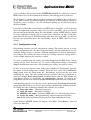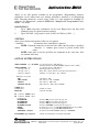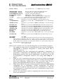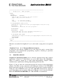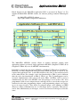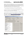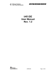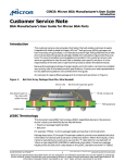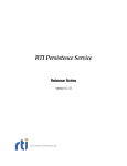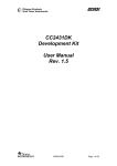
1
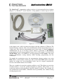
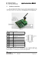
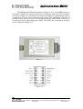
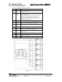
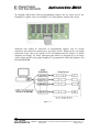
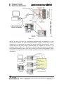
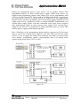
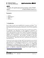
Application Note AAN056
AN056
GangPro-CC and Production Programming of the CC2430
SWRA157
By Gregory Czajkowski - Elprotronic Inc.
Keywords
•
•
•
•
•
“CC2430"
“Flash Programmer”
“GangPro-CC”
“ZigBee”
“Serialization”
1. Introduction
The CC2430 is the first single chip IEEE 802.15.4 compliant and ZigBee TM SoC
(System on Chip) RF Transceiver with integrated 8051 microcontroller and memory
flash. Method of the flash programming in production is discussed in this application
note.
This application note describes flash programming of the CC2430 using the GangProCC programmer from Elprotronic. A single GangPro-CC programmer can
simultaneously program and automatically assign an IEEE address for up to six target
devices. When more then six target devices should be programmed simultaneously,
then more GangPro-CC programmers can be used and controlled via the Multi-FPA
API-DLL. Up to eight programmers can be controlled from external software written
in MS Visual C++, Borland C++, MS Visual Basic, LabVIEW etc. which allow
simultaneous programming of up to 48 target devices. Effectively, this method allows
for programming of whole PCB panel before depanelization and speeds-up the
programming process.
A target device can be used by any board with CCxx SoC that has access to the SoC
2-wire debug interface (Debug Clock (DC), Debug Data (DD) and Reset line). In this
application note the CC2430 ZigBee Development Kit as a target device (Battery
Board SOC_BB 1.1 and CC2430EM 1.2) has been used as an example. This
development kit is described in detail in TI’s application note SWRU073B
“CC2430ZDK and CC2431ZDK ZigBee Development Kit Pro”. The GangPro-CC is
described in Elprotronic’s manuals PM025A01 “GangPro-CC Programmer User’s
Guide” and PM025A02 “GangPro-CC API-DLL User’s Guide” available on
http://www.elprotronic.com/download.html
SWRA157 AN056 GangPro-CC and Production Programming of the CC2430 (Rev. 1.0)
2007-09-24
Page 1 of 21
Application Note AAN056
The GangPro-CC programmer package consists of a microcontroller based adapter
(Figure 1-1), WindowsTM based software, a Gang Splitter to connect up to 6 devices
Figure 1-1
to the adapter, and a cable to connect the adapter with the computer’s USB port. The
internal firmware software allows for communication with the programmed device at
a high speed. The effective programming speed (write only) is around 20 kbytes/s
simultaneously for up to six target devices which is equivalent to 120 kbytes/s
programming speed per one programmed target device. For example, six devices with
128 kB Flash, such as CC2430F128, can be programmed in 12 seconds. This time
includes initialization, erasing memory, blank checking, programming and fast
verification.
To simplify the production process the programming software package can assign
IEEE address, serial number, model type, and revision. Each IEEE address and serial
number are unique for each programmed device and are assigned automatically.
Several serial number formats are available.
There are a number of erase/write options available as well. This allows to erase/write
all flash memory, or just the specified fragment of memory. This feature is very
useful when only part of programmed data/code should be replaced. For example one
can download the serial number, calibration data or personality data without erasing
existing program code.
SWRA157 AN056 GangPro-CC and Production Programming of the CC2430 (Rev. 1.0)
2007-09-24
Page 2 of 21
Application Note AAN056
2.
Hardware connection
TI’s development board (Figure 2-1) uses a 10 pin connector (Figure 2-2) for
communication with the CCxx devices, which allows to program target device via
“SoC debug” interface (via connector P5 - SoC debug/flash on the SOC_BB board).
Figure 2-1
Table 2.1 Target’s Device connector
Pin
#
Name
Description
1
GND
Ground
2
Vdd / Sense
Vdd used to set correct voltage for the
voltage level connector and can be used to
supply target device.
3
DC
Debug Clock
4
DD
Debug Data
5
do not use
do not use
6
do not use
do not use
7
RST
RESET - Active LOW
8
do not use
do not use
9
Vdd / alt NC
Deliver Vdd from external source
(OPTIONAL)
Header - Top View
Figure 2-2
From all available pins only 5 pins (pin numbers 1,2,3,4,7 - respectively GND, Vdd,
DC, DD, RST) should be used for communication with the MCU via SoC debug
interface (Table 2.1) . All other pins are used for other applications.
SWRA157 AN056 GangPro-CC and Production Programming of the CC2430 (Rev. 1.0)
2007-09-24
Page 3 of 21
Application Note AAN056
The GangPro-CC Flash Programmers (Figure 2-3) use the 14-pin connector
to facilitate connections with six target devices. Connector layout and pin descriptions
are shown on Figure 2-4 and Table 2.2. When the GangPro-CC programming adapter
is connected to target devices then all clock signals (DC) should be connected in
parallel to target devices and all six bidirectional data lines (DD) should be connected
to each target device. Remaining lines (RST, Vdd, GND) are connected to all target
devices in parallel (Figure 2-5).
Figure 2-3
Header - Top View
Figure 2-4
SWRA157 AN056 GangPro-CC and Production Programming of the CC2430 (Rev. 1.0)
2007-09-24
Page 4 of 21
Application Note AAN056
Table 2.2 GangPro-CC Interface connector
Pin #
Name
Description
1
(Red)
DD-1
Debug Data output / Input - 1
2
Vdd /
Sense
Vdd supplied to the target ( 2.2 to 3.6V/ max 100 mA) and the
target’s Vdd voltage sense.
This pis should be connected to target’s device Vdd if device
is supplied from the Flash Programming Adapter. If the
target’s device is supplied from his own battery or from
external power supply then the pin 2 or 4 (Vdd sense) should
be connected to device’s Vdd.
3
Busy
BUSY - 1 when the communication with target is active.
4
Sense
Target’s Device Vdd Sense (see pin-2 description)
5
do not
use
do not use
6
DD-2
Debug Data output / Input - 2.
7
DC
Debug Clock - common clock to all target devices
8
Vdd-En
Used to control external power supply. Voltage 2 to 5V ->
Power Supply ON
9
GND
Ground
10
DD-3
Debug Data output / Input - 3.
11
\RST
Reset output
Figure 2-5
SWRA157 AN056 GangPro-CC and Production Programming of the CC2430 (Rev. 1.0)
2007-09-24
Page 5 of 21
Application Note AAN056
To simplify connections between programming adapter and six target devices the
GangPro-CC splitter can be used (Figure 2-6). Gang Splitter contains one 14-pin
Figure 2-6
connector that should be connected to programming adapter, and six 10-pin
connectors that should be connected to six target devices. Pinout of the six 10-pin
connectors is the same as the pinout in TI’s development boards. Figure 2-7 (block
diagram) and Figure 2-8 show connection that allows to program up to 48 target
devices from one PC using eight GangPro-CC programmers with Gang Splitters and
D-Link USB-HUB.
Figure 2-7
SWRA157 AN056 GangPro-CC and Production Programming of the CC2430 (Rev. 1.0)
2007-09-24
Page 6 of 21
Application Note AAN056
Figure 2-8
When a lot of target devices are programmed simultaneously in production, it is not
convenient to connect all cables from programming adapters to each target device
separately. It is recommended to prepare test bench with nails, that allows to connect
all boards from the panel (before depanelization) to GangPro-CC directly or via
GangPro Splitters (Figure 2-8). Target device boards should be specially designed for
it and should contain test points that can be connected via nails to programmer. When
all boards are programmed (and eventually partially tested) then all boards can be
depanelized.
Figure 2-9
SWRA157 AN056 GangPro-CC and Production Programming of the CC2430 (Rev. 1.0)
2007-09-24
Page 7 of 21
Application Note AAN056
During the programming process target devices can be supplied directly from
programming adapters or from external power supply. When target devices are
supplied from programming adapters then voltage level can be programmable from
2.2V to 3.6V with step of 0.2V. Current load up to 100 mA (this means - up to 16 mA
per target device if up to six target devices are connected to one programming
adapter). If this current is not sufficient, then external power supply should be used to
supply target devices. GangPro-CC allows to control ON/OFF (enable/disable) and
external power supply. Figure 2-10 show connection of the target devices supplied
from programming adapter or from external power supply. If an external power
supply is used, then it is recommended to connect pull-down load (eg. resistor 10k)
between power’s supply enable input and ground.
Pin 2 (Vdd/Sense) of the programming adapter must be connected to Vdd of target
devices, even if the external power supply is used. The Vdd level from the target
devices is used to supply the voltage level translator, that allows to convert logic
levels from/to programming adapter’s microcontroller from 3.3V to/from levels
required by the target devices (2.2V to 3.6V).
Figure 2-10
SWRA157 AN056 GangPro-CC and Production Programming of the CC2430 (Rev. 1.0)
2007-09-24
Page 8 of 21
Application Note AAN056
3.
Software
GangPro-CC programmer package contains two types of software that allow to
program target devices via USB-FPA programming adapter.
First - application software contains graphic user interface (GUI). This software
allows to control one programming adapter (USB-FPA) connected up to six target
devices to this adapter. Software allows to erase, blank check, program and verify
memory flash in target device. Full or part of the flash memory can be erased,
programmed and verified. The IEEE address and serialization can be automatically
generated and saved in the flash memory. Available script file option allows to create
custom defined programming sequence. See Elprotronic’s manual PM025A01
“GangPro-CC Programmer User’s Guide” for details.
Second - the Multi-FPA API DLL allows to simultaneously control up to eight
programming adapters (USB-FPA). Up to six target devices can be connected to each
programming adapter. In total - up 48 target devices can be programmed
simultaneously using Multi-FPA API-DLL. When the Multi-FPA API-DLL is used
then the application software which uses this DLL should be written by the user.
Application software can be written in Visual C++, Visual Basic, LabVIEW etc. The
IEEE address and serialization should be generated by application software if these
numbers are required. List of available instructions are specified and described in the
Elprotronic’s manual PM025A02 “GangPro-CC API-DLL User’s Guide”.
3.1
Application software with GUI
To start the GangPro-CC programmer click on the GangPro-CC Elprotronic icon
(Figure 3-1).
Once started the software will attempt to access the programming adapter. If no error
messages appear then the software has initialized without a problem and you may
begin using it. However, if the programming adapter is not detected an error message
will appear. To correct the problem, make sure that the connection cable is properly
attached and the USB driver is installed.
Figure 3-1
SWRA157 AN056 GangPro-CC and Production Programming of the CC2430 (Rev. 1.0)
2007-09-24
Page 9 of 21
Application Note AAN056
The programming dialogue box (Figure 3-2.) contains a pull down menu, interface
selection box, lock protection bits box, device action buttons, report (status) window,
open file buttons, target device information box, IEEE addresses and serial number
box, power DC status and check sum result boxes. At the beginning, desired target
device type should be selected. In our example when the TI’s CC2430ZDK boards
are used, in the SoC Device Type group it should be selected device - CC2430F128
(Flash size 128 kB). When the target devices are supplied power from programming
adapter, then in the Power Device from Adapter group desired voltage and Enable
box should be selected. Using Open Code File button requested code file should be
opened. Three code formats are accepted - TI hex (*txt), Intel hex (*.hex) and
Motorola s (*.s19, *.s28 or *.s37). In the Target Devices Programming Result group
the Target Enable should be selected. A minimum of one target device should be
enabled. If more then one target device are connected to programmer, then all target
devices must be the same type. Size of the desired flash memory to be erased and
programmed can be defined in the Memory Option dialogue screen (Figure 3-3)
accessible from pull down menu - Setup->Memory Option. Typically All Memory
option should be selected. In the Retain Flash Data group a part of flash memory can
be selected, of which the contents will be restored after erase and programming. This
option is useful if flash contains calibrated data and data should not be erased after
Figure 3-2
programming process. Retain data block sizes can be up to 2048 bytes and can be
located at any place - in one or more flash sectors. When the programmed contents
are modified only in part of flash memory, then the Used Defined option can specify
SWRA157 AN056 GangPro-CC and Production Programming of the CC2430 (Rev. 1.0)
2007-09-24
Page 10 of 21
Application Note AAN056
four flash blocks that can be erased and programmed. It should be noted, that if any
part of flash segment is specified in the defined block, then full segment will be
erased (typical flash segment size is 2 kB for flash size 128 kB), however only
specified flash address range will be programmed and verified. In the field Flash
Lock Bits after Autoprogram the desired option that allows to protect selected part of
flash memory (selected flash memory, boot sector or access to debug option) when
flash is programed should be selected. Selected flash segments cannot be modified by
application program when they are protected. User should know if their application
program has access to modify flash memory, otherwise application program cannot
work if access to write protected flash is required. If the lock bits are programmed in
target devices and access to target device is blocked, it is possible to get access to
target device again, but only if full flash memory will be erased. It is not possible to
retain any data if debug bit is locked. To automatically unlock and erase full memory
contents if lock bits are programmed in the target device, the Unlock debug option
should be selected in the Memory Erase/Program and Verify group (Figure 3-3).
Figure 3-3
When desired configuration is selected then in the Main Dialogue screen (Figure 3-2)
the Lock Protection Bits option can be used to enable or disable programming of
selected lock bits.
SWRA157 AN056 GangPro-CC and Production Programming of the CC2430 (Rev. 1.0)
2007-09-24
Page 11 of 21
Application Note AAN056
When Autoprogram is pressed, then selected target devices should be erased,
programmed and verified. Following information should be displayed in the Report
window (Figure 3-4). If serialization and IEEE address are not selected, then the lines
related to these items will not be displayed.
Figure 3-4
In the Target Device Programming Result (Figure 3-5) should be displayed all OK
icons if all targets are programmed and verified successfully. If programming process
in one target failed (eg. erase failed) then process in all other targets is continued as
long as minimum one target is programmed without errors. At the end one
programmer target without errors will have green (OK) icon, while others - red
(ERROR) icons in location where the errors has been detected.
Figure 3-5
3.1.1 IEEE Address and Serialization
The GangPro-CC programming software has the ability to automatically create the
target device’s IEEE Address and Serial Number and save it in flash memory. These
numbers are also saved in the database file. The new IEEE Address and Serial
Number can be created automatically by incrementing the IEEE Address and Serial
Number or can be taken from a file created by the user. Furthermore, model name,
group, and revision can be downloaded to target device. The IEEE Address format
contains 8 bytes located at the end of the flash memory or specified location of the
SWRA157 AN056 GangPro-CC and Production Programming of the CC2430 (Rev. 1.0)
2007-09-24
Page 12 of 21
Application Note AAN056
flash memory and can be saved in order - LSB or MSB byte first. The Serial Number
format and location in the device’s flash memory must be specify by the user.
IEEE Address and Serial Number are created when the Auto Program or Write SN
/Write IEEE Addr button is pressed and the Serialization feature is enabled. When
the Auto Program function is activated then the IEEE Address and/or Serial Number
are programmed to the target device’s memory along with the code data. If the Auto
Program function fails for any reason then new IEEE Address / Serial Number is
not created.
The software also allows the device to retain its IEEE Address / Serial Number if
one has already been assigned to it. Every time a device is programmed and
serialization is enabled the contents of the target’s memory are scanned for existing
IEEE Address and Serial Number. If numbers are found in the database, the
dialogue screen will appear and allow you to decide if you wish to keep the old IEEE
Address / Serial Number, new or manually entered once. See User’s Guide for
details. The IEEE Address setup and Serialization setup are accessible from pulldown menu IEEE/Serialization Setup. When the IEEE Address and Serialization
Setup is selected then following dialogue screen is displayed (Figure 3-6).
The IEEE address can be created automatically by incrementing the IEEE address
from specified value (see Figure 3-6), or can be taken sequentially from user defined
file containing list of required IEEE Addresses. All assigned IEEE addresses are
Figure 3-6
SWRA157 AN056 GangPro-CC and Production Programming of the CC2430 (Rev. 1.0)
2007-09-24
Page 13 of 21
Application Note AAN056
saved in database file specified in the SN/IEEE Record File line. When the assigned
IEEE address has also been found in the database, then warning will be displayed.
The GangPro-CC software allows to generate unique serial numbers that can be saved
in any flash location. Serialization format and location in flash memory should be
specified by user (see Figure 3-6). All serialization options are described in detail in
the User’s Guide.
It should be noticed that Serial Number and IEEE address should be saved in location
where the application program is empty. Not any data (even 0xFF) can be specified in
the code data in the location where the serial number, model or IEEE Address should
be saved. Otherwise warning will be created and verification can fail. Verification
procedure will find data in FLASH location other than data (even 0xFF) specified in
the code data at location where the serial number, model or IEEE address has been
written.
3.1.2 Configuration setup
Programming software can save configuration settings. This allows the user to create
several configuration files, one for each particular task, and thus eliminate the need to
manually change settings every time a different configuration is desired. Furthermore,
the config.ini file contains the most recently used settings and those settings will be
used as default whenever the software is started.
To create a configuration file simply select Save Setup from the File menu. Current
settings will be saved for future use. To restore configuration settings select Load
Setup from File menu and select a file containing the settings you wish to restore.
In order to prevent accidental setup changes the GangPro-CC Programmer provides
the option to Lock configuration settings. When the user selects the Lock/Unlock
Setup option from the Setup menu, the Programmer will prevent the user from
modifying the setup. The only options that are available when the programmer is
locked are Verify, Read, Autoprogram and Next. Notice that the Next button will
immediately change to implement the Autoprogram function. To unlock the
programmer the user must select the Lock/Unlock Setup option from the Setup menu.
Configuration setup file (or Code file) can be opened using Load Setup (Load Code)
option from File menu or can also be opened using command line combined with the
executable file name. Following command line switches are available
-sf Setup_file_name ( Download setup file )
-cf Code_file_name ( Download Code file )
-nf IEEE/SN_ file_name (Download IEEE addresses / Serial number list file )
-rf Script_file_name ( Run programming sequence from the Script File )
-lock (Lock almost all buttons. Prevent the user from modifying the setup)
Using Windows START button (left bottom) select Run.. Using Browse.. find and
select executable file
SWRA157 AN056 GangPro-CC and Production Programming of the CC2430 (Rev. 1.0)
2007-09-24
Page 14 of 21
Application Note AAN056
“C:\Program Files\Elprotronic\CCxx\USB GangPro-CC\GangPro-CC.exe"
and at the end enter the required key with name of the setup file and extra key “-lock”
can be added if required, eg.
“C:\Program Files\Elprotronic\CCxx\USB GangPro-CC\GangPro-CC.exe” -lock -sf C:\MFG\prg-04.cfg
On Figure 3-7 the Main GUI dialogue screen is presented with locked buttons when
the “-lock” option is used. Only few buttons are active that can run programmer, but
all buttons/pull down menu that can modify programmer’s setup are blocked.
Instead writing above command every time when the programmed is activated, it is
possible to create icons with parameters listed above and use selected icon from the
desktop to activate programmer with required switches. See User’s Guide for details.
3.1.3 User defined programming sequence - Scrip File
Figure 3-7
Programming sequence can be customized using script file. Script file prepared as a
text file (using any editor like notepad) can contain customized programming
sequences in any order. Generally, all buttons available on the main dialogue screen
can be used in the script file. All other options available on others screens like
memory options, serialization type etc. cannot be modified from the script file
directly, but can be reloaded in fully using configuration file. From the script file any
configuration files can be called at any time that allows to modify programmer
configuration. This method can simplify programming process using script file and
SWRA157 AN056 GangPro-CC and Production Programming of the CC2430 (Rev. 1.0)
2007-09-24
Page 15 of 21
Application Note AAN056
allows to use full options available in the programmer. Programming sequence
conditions can be taken from user defined procedures attached as an independent
DLL. Function should be created using Visual C++ and attached to GangPro-CC
software. See Elprotronic’s manuals PM025A01 “GangPro-CC Programmer User’s
Guide” for details.
LIMITATIONS:
1.
Up to 1000 script lines commands can be used. Empty lines and lines with
comments only are ignored and not counted.
2.
Up to 50 CALL’s deep stack is used (CALL in CALL in CALL......).
SYNTAX:
white spaces before instructions, labels etc are ignored.
; comment
- all contents after semicolon are ignored.
NOTE: Comment cannot be used in the lines where the file name is specified.
>label
- character ‘>’ without spaces must be placed before label
name.
NOTE: After label ca not be specified any command in the same line. Line
can contain label only.
LIST OF INSTRUCTIONS:
MESSAGEBOX type FCTEXT - pop-up message box with buttons.
- message taken from the FCONTROL function (User’s DLL)
MESSAGEBOX type
- pop-up message box with buttons.
“ message - line -1 “
- Text displayed in message box.
“ message - line -2 “
- Each line contents must be located between characters “ ”
“ max up to 50 lines “
- Number of content lines - up to 50 lines.
Message box type list
OK
OKCANCEL
YESNO
YESNOCANCEL
- One button OK
- Two buttons OK , CANCEL
- Two buttons YES , NO
- Three buttons YES , NO, CANCEL
GOTO label
CALL label
RETURN
- CALL procedure.
- return from CALL.
IF condition GOTO label
IF condition CALL label
condition list:
BUTTONOK
BUTTONYES
BUTTONNO
BUTTONCANCEL
DONE
FAILED
CONTROL = number
- if button OK pressed in the message box.
- if button YES pressed in the message box.
- if button NO pressed in the message box.
- if button CANCEL pressed in the message box.
- if selected process e.g. AUTOPROGRAM finished successfully.
- if selected process e.g. AUTOPROGRAM failed.
- if status from the FCONTROL function = NUMBER
FCONTROL type argument
- call the external function from FxControl DLL
SWRA157 AN056 GangPro-CC and Production Programming of the CC2430 (Rev. 1.0)
2007-09-24
Page 16 of 21
Application Note AAN056
PAUSE
number
- pause in miliseconds - 1 to 100000 range (1ms to 100 s).
OPENDLLFILE filename
- FxControl DLL file - Full path and DLL File name.
LOADCFGFILE filename
- Configuration file - Full path and File name.
LOADCODEFILE filename
- Code file - Full path and File name.
LOADSNFILE filename
- IEEE/SN file - Full path and File name.
VCCOFF
- Turn OFF Vcc from programming adapter to target device.
VCCON
- Turn ON Vcc from programming adapter to target device.
Note: Vcc from FPA must be enabled first using configuration file.
RESET
-equivalent to pressed button RESET on the main dialogue screen.
AUTOPROGRAM
-equivalent to pressed button AUTOPROGRAM on the main dialogue
screen.
VERIFYACCESS
-equivalent to pressed button VERIFY LOCK BIT on the main dialogue
screen.
ERASEFLASH
-equivalent to pressed button ERASE FLASH on the main dialogue screen.
BLANKCHECK
-equivalent to pressed button BLANK CHECK on the main dialogue screen.
WRITEFLASH
-equivalent to pressed button WRITE FLASH on the main dialogue screen.
VERIFYFLASH
-equivalent to pressed button VERIFY FLASH on the main dialogue screen.
READFLASH
-equivalent to pressed button READ/COPY on the main dialogue screen.
READSN
-equivalent to pressed button READ SN on the main dialogue screen.
READIEEE
-equivalent to pressed button READ IEEE Addr on the main dialogue
screen.
LOCKFLASH
-equivalent to pressed button LOCKFLASH on the main dialogue screen.
TRACEOFF
- trace OFF.
TRACEON
- trace ON and saved in the “Trace-Scr.txt” file in current working directory.
Option useful for debugging. Trace file contains sequence of all executed commands from
script file in the run time. On the left side of all lines the current line numbers correspondent to
the line number in the script file are printed. Line numbers are counted without empty lines
and without lines contains comments only.
END
- end of script program.
Below are the contents of an easy script file that allows to create following sequence;
1.
Vcc supplied to target device is turn-OFF and first message box with buttons
OK/CANCEL is displayed. Programmer is waiting until button OK or
CANCEL is pressed.
2.
When confirmed, then first configuration file test-A.cfg is downloaded to
programmer. Configuration file test-A.cfg should be prepared first using
programming software with desired configuration, selected desired code file
etc. Programmer’s configuration should be saved using “Save setup us ..”
option.
3.
When test code is downloaded and processor started (if enabled in test-A.cfg
file) then message box is displayed and software is waiting until button YES /
NO is press. Meantime manual target’s device test can be done. If test is
positive, then button OK should be pressed, or button NO if test failed.
4.
When button OK has been pressed then programmer downloads finalcode.cfg
configuration file to programmer. Current configuration can activate
serialization if required, reload final code to be downloaded etc. When the
new configuration is reloaded then final code is downloaded to target device,
serialization is created etc.
5.
On the end, programmer returns to beginning and waits for the next target
device to be connected.
SWRA157 AN056 GangPro-CC and Production Programming of the CC2430 (Rev. 1.0)
2007-09-24
Page 17 of 21
Application Note AAN056
;=====================================================
;
Script file - demo program
;---------------------------------------------------->START
VCCOFF
MESSAGEBOX
OKCANCEL
"VCC if OFF now. Connect the test board."
"When ready press the button:"
" "
"OK
- to test the board"
"CANCEL - to exit from program"
IF BUTTONCANCEL GOTO finish
LOADCFGFILE C:\Elprotronic\Project\Cpp\GangPro-CC\test-A.cfg
MESSAGEBOX
OK
"Press OK to download the test program."
AUTOPROGRAM
MESSAGEBOX
YESNO
"Press YES when the test finished successfully."
"Press NO when the test failed."
IF BUTTONNO GOTO START
LOADCFGFILE C:\Elprotronic\Project\Cpp\GangPro-CC\finalcode.cfg
AUTOPROGRAM
GOTO START
>finish
END
;=======================================================
When the executable file GangPro-CC.exe is called with a script path as an argument
e.g.
GangPro-CC.exe -rf C:\Program Files\test\script.txt
or when the icon with the GangPro-CC.exe and script file path is executed then
programmer starts automatically programming sequences according to procedure
specified in the script file.
3.2
Multi-FPA API-DLL
GangPro-CC Flash Programmer can be remotely controlled from other software
applications (Visual C++, Visual Basic etc.) via a DLL library. The Multi-FPA allows to remotely control up to eight Flash Programming Adapters (FPAs)
simultaneously significantly reducing programming production time.
Figures 2-7 and 2-8 show the connections between PC and up to eight programming
adapters. The FPAs can be connected to PC USB ports directly or via USB-HUB.
Direct connection to the PC is faster but if the PC does not have required number of
USB ports, then USB-HUB can be used. The USB-HUB should be fast, otherwise
speed degradation can be noticed. When the USB hub is used, then the D-Link’s
Model No: DUB-H7, P/N BDUBH7..A2 USB 2.0 HUB is recommended.
SWRA157 AN056 GangPro-CC and Production Programming of the CC2430 (Rev. 1.0)
2007-09-24
Page 18 of 21
Application Note AAN056
Block diagram of the Multi-FPA application DLL is presented on Figure 3-8. To
support the Multi-FPA API-DLL feature, the software package contains following dll
files
- the Multi-FPA API-DLL selector
- up to eight standard single FPAs API-DLLs
Figure 3-8
The Multi-FPA API-DLL selector allows to transfer functions coming from
application software to desired single application API-DLL (GangProCC-FPA1.dll to
GangProCC-FPA8.dll) or to all API-DLL simultaneously.
It should be noticed that all single API-DLLs (GangProCC-FPA1.dll to GangProCCFPA8.dll) are fully independent from each other. From that point of view it is not
required that transferred data to one FPA should be the same as the transferred data
to the others FPAs. For example, code data downloaded to FPA-1 can be different
than the code data downloaded to FPA-2, FPA-3 etc. The F_AutoProgram can be
executed simultaneously with selected all active FPAs. All FPAs will be serviced
simultaneously by their own API-DLL and data packages saved in these dlls. Also
programmers allow to save unique data to each target devices even if these targets are
connected to the same programming adapter (each programming adapter can service
up to six target devices). This allows to program unique serial numbers or IEEE
addresses, unique calibration data etc. to each target devices separately. This process
can be done simultaneously to all targets, even if saved data to each targets are not the
same.
SWRA157 AN056 GangPro-CC and Production Programming of the CC2430 (Rev. 1.0)
2007-09-24
Page 19 of 21
Application Note AAN056
Software package provided by Elprotronic Inc. contains all required Multi-FPA APIDLL files, as well as demo programs with source code written under Visual C++.
Demo programs software can be modified by user for custom requirements. One of
the presented demo program allows to simultaneously control up to eight gang
programming adapters that allows to program up to 48 target devices.
Source code and all related project files are located in the following directory:
C:\Program Files\Elprotronic\CCxx\USB GangPro-CC\API-DLL-Demo\Cpp\Demo-8x6
Program can be activated by selecting the GangProCC-8x6-Demo.exe in the \release
subdirectory, or can be activated from the windows menu:
Start->Program->Elprotronic-Flash Programmer->(CCxx) USB GangPro-CC->API-DLL-8x6-Demo-Cpp
When the program is executed, then following GUI dialogue screen is displayed (see
Figure 3-9). See the Elprotronic’s manual PM025A02 “GangPro-CC API-DLL
User’s Guide” available on http://www.elprotronic.com/download.html for detailed
descriptions of all available instructions in the Multi-FPA API-DLL and description
of the demo programs included in the GangPro-CC software package.
Figure 3-9
SWRA157 AN056 GangPro-CC and Production Programming of the CC2430 (Rev. 1.0)
2007-09-24
Page 20 of 21
Application Note AAN056
References
1.
“CC2430ZDK and CC2431ZDK ZigBee Development Kit Pro” - TI’s
application note SWRU073B
2.
“GangPro-CC Flash Gang Programmer for the CC series devices
User’s Manual” - Elprotronic’s GangPro-CC User’s Guide PM025A01
3.
“GangPro-CC Flash Programmer for the CC series devices - Chipcon
product from TI. Remote Control Programming User’s Guide” Elprotronic’s GangPro-CC API-DLL User’s Guide - PM025A02
Document History
Revision
Date
1.0
2007-09-24
Description/Changes
Initial release.
SWRA157 AN056 GangPro-CC and Production Programming of the CC2430 (Rev. 1.0)
2007-09-24
Page 21 of 21
IMPORTANT NOTICE
Texas Instruments Incorporated and its subsidiaries (TI) reserve the right to make corrections, modifications, enhancements,
improvements, and other changes to its products and services at any time and to discontinue any product or service without notice.
Customers should obtain the latest relevant information before placing orders and should verify that such information is current and
complete. All products are sold subject to TI’s terms and conditions of sale supplied at the time of order acknowledgment.
TI warrants performance of its hardware products to the specifications applicable at the time of sale in accordance with TI’s
standard warranty. Testing and other quality control techniques are used to the extent TI deems necessary to support this
warranty. Except where mandated by government requirements, testing of all parameters of each product is not necessarily
performed.
TI assumes no liability for applications assistance or customer product design. Customers are responsible for their products and
applications using TI components. To minimize the risks associated with customer products and applications, customers should
provide adequate design and operating safeguards.
TI does not warrant or represent that any license, either express or implied, is granted under any TI patent right, copyright, mask
work right, or other TI intellectual property right relating to any combination, machine, or process in which TI products or services
are used. Information published by TI regarding third-party products or services does not constitute a license from TI to use such
products or services or a warranty or endorsement thereof. Use of such information may require a license from a third party under
the patents or other intellectual property of the third party, or a license from TI under the patents or other intellectual property of TI.
Reproduction of TI information in TI data books or data sheets is permissible only if reproduction is without alteration and is
accompanied by all associated warranties, conditions, limitations, and notices. Reproduction of this information with alteration is an
unfair and deceptive business practice. TI is not responsible or liable for such altered documentation. Information of third parties
may be subject to additional restrictions.
Resale of TI products or services with statements different from or beyond the parameters stated by TI for that product or service
voids all express and any implied warranties for the associated TI product or service and is an unfair and deceptive business
practice. TI is not responsible or liable for any such statements.
TI products are not authorized for use in safety-critical applications (such as life support) where a failure of the TI product would
reasonably be expected to cause severe personal injury or death, unless officers of the parties have executed an agreement
specifically governing such use. Buyers represent that they have all necessary expertise in the safety and regulatory ramifications
of their applications, and acknowledge and agree that they are solely responsible for all legal, regulatory and safety-related
requirements concerning their products and any use of TI products in such safety-critical applications, notwithstanding any
applications-related information or support that may be provided by TI. Further, Buyers must fully indemnify TI and its
representatives against any damages arising out of the use of TI products in such safety-critical applications.
TI products are neither designed nor intended for use in military/aerospace applications or environments unless the TI products are
specifically designated by TI as military-grade or "enhanced plastic." Only products designated by TI as military-grade meet military
specifications. Buyers acknowledge and agree that any such use of TI products which TI has not designated as military-grade is
solely at the Buyer's risk, and that they are solely responsible for compliance with all legal and regulatory requirements in
connection with such use.
TI products are neither designed nor intended for use in automotive applications or environments unless the specific TI products
are designated by TI as compliant with ISO/TS 16949 requirements. Buyers acknowledge and agree that, if they use any
non-designated products in automotive applications, TI will not be responsible for any failure to meet such requirements.
Following are URLs where you can obtain information on other Texas Instruments products and application solutions:
Products
Applications
Amplifiers
amplifier.ti.com
Audio
www.ti.com/audio
Data Converters
dataconverter.ti.com
Automotive
www.ti.com/automotive
DSP
dsp.ti.com
Broadband
www.ti.com/broadband
Interface
interface.ti.com
Digital Control
www.ti.com/digitalcontrol
Logic
logic.ti.com
Military
www.ti.com/military
Power Mgmt
power.ti.com
Optical Networking
www.ti.com/opticalnetwork
Microcontrollers
microcontroller.ti.com
Security
www.ti.com/security
RFID
www.ti-rfid.com
Telephony
www.ti.com/telephony
Low Power
Wireless
www.ti.com/lpw
Video & Imaging
www.ti.com/video
Wireless
www.ti.com/wireless
Mailing Address: Texas Instruments, Post Office Box 655303, Dallas, Texas 75265
Copyright © 2007, Texas Instruments Incorporated