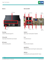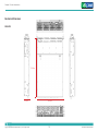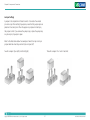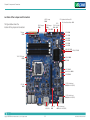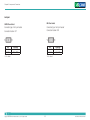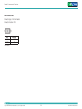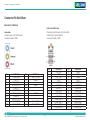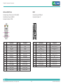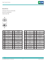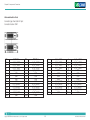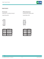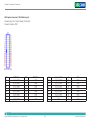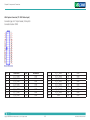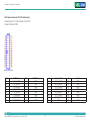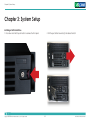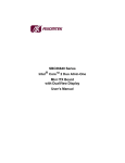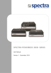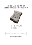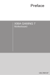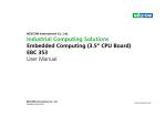
1
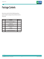
NEXCOM International Co., Ltd. Intelligent Digital Security Intelligent Survillance Solution NViS 6210/6220 User Manual NEXCOM International Co., Ltd. Published March 2012 www.nexcom.com Contents Contents Preface iv Knowing Your NViS 6210................................................................. 8 Knowing Your NViS 6220............................................................... 13 Mechanical Dimensions.................................................................. 18 Copyright.........................................................................................iv Disclaimer........................................................................................iv Acknowledgements..........................................................................iv Regulatory Compliance Statements..................................................iv Declaration of Conformity................................................................iv RoHS Compliance..............................................................................v Warranty and RMA...........................................................................vi Safety Information........................................................................... vii Installation Recommendations......................................................... vii Safety Precautions.......................................................................... viii Technical Support and Assistance.....................................................ix Conventions Used in this Manual.....................................................ix Global Service Contact Information...................................................x Package Contents........................................................................... xii Ordering Information...................................................................... xiii Chapter 1: Product Introduction Chapter 2: Jumpers and Connectors Before You Begin............................................................................ 20 Precautions..................................................................................... 20 Jumper Settings.............................................................................. 21 Locations of the Jumpers and Connectors...................................... 22 Jumpers......................................................................................... 23 CMOS Clear Select............................................................... 23 ME Clear Select.................................................................... 23 Power Mode Select............................................................... 24 Connector Pin Definitions............................................................... 25 External I/O Interfaces........................................................... 25 Audio Jacks.......................................................................... 25 LAN1 and USB0/1 Ports........................................................ 25 LAN2 and USB2/3 Ports........................................................ 26 HDMI.................................................................................... 26 VGA and DVI-D Ports............................................................ 27 Video and Audio In Ports...................................................... 28 1 Overview.......................................................................................... 1 Hardware Specifications................................................................... 4 Copyright © 2012 NEXCOM International Co., Ltd. All rights reserved 6 ii NViS 6210 / 6220 User Manual Contents Internal Connectors........................................................................ 29 CPU Fan Connector.............................................................. 29 ATX Power Output Connector.............................................. 29 ATX Power Connector.......................................................... 30 System Fan Connectors......................................................... 30 COM1 Connector................................................................. 31 COM2 Connector................................................................. 31 GPIO Connector................................................................... 32 Front Panel Control Connector.............................................. 32 Keyboard and Mouse............................................................ 33 SATA 3.0 Ports...................................................................... 33 SATA 2.0 Connectors............................................................ 34 USB Connectors.................................................................... 34 Mini-PCIe Slot....................................................................... 35 PCIEX1 to SATA2.0 Connectors............................................. 36 PCIe x16 Slot........................................................................ 37 VGA Capture Connector (1-16CH Video Input)..................... 39 Copyright © 2012 NEXCOM International Co., Ltd. All rights reserved VGA Capture Connector (17-32CH Video Input)................... 40 VGA Capture Connector (17-32CH Audio Input).................. 41 Chapter 3: System Setup 42 Installing a SATA Hard Drive............................................................ 42 Removing the Chassis Cover........................................................... 45 Chapter 4: BIOS Setup 47 About BIOS Setup.......................................................................... 47 When to Configure the BIOS.......................................................... 47 Default Configuration.................................................................... 48 Entering Setup............................................................................... 48 Legends......................................................................................... 48 BIOS Setup Utility........................................................................... 50 iii NViS 6210 / 6220 User Manual Preface Preface Copyright other product names mentioned herein are registered trademarks of their respective owners. This publication, including all photographs, illustrations and software, is protected under international copyright laws, with all rights reserved. No part of this manual may be reproduced, copied, translated or transmitted in any form or by any means without the prior written consent from NEXCOM International Co., Ltd. Regulatory Compliance Statements This section provides the FCC compliance statement for Class B devices and describes how to keep the system CE compliant. Disclaimer Declaration of Conformity The information in this document is subject to change without prior notice and does not represent commitment from NEXCOM International Co., Ltd. However, users may update their knowledge of any product in use by con-stantly checking its manual posted on our website: http://www.nexcom.com. NEXCOM shall not be liable for direct, indirect, special, incidental, or consequential damages arising out of the use of any product, nor for any infringements upon the rights of third parties, which may result from such use. Any implied warranties of merchantability or fitness for any particular purpose is also disclaimed. FCC This equipment has been tested and verified to comply with the limits for a Class B digital device, pursuant to Part 15 of FCC Rules. These limits are designed to provide reasonable protection against harmful interference when the equipment is operated in a commercial environment. This equip-ment generates, uses, and can radiate radio frequency energy and, if not installed and used in accordance with the instructions, may cause harmful interference to radio communications. Operation of this equipment in a residential area (domestic environment) is likely to cause harmful interfer-ence, in which case the user will be required to correct the interference (take adequate measures) at their own expense. Acknowledgements NViS 6210/6220 is a trademark of NEXCOM International Co., Ltd. All Copyright © 2012 NEXCOM International Co., Ltd. All rights reserved iv NViS 6210 / 6220 User Manual Preface CE Chromium (Cr6+) < 0.1% or 1,000ppm, Polybrominated biphenyls (PBB) < 0.1% or 1,000ppm, and Polybrominated diphenyl Ethers (PBDE) < 0.1% or 1,000ppm. The product(s) described in this manual complies with all applicable Euro-pean Union (CE) directives if it has a CE marking. For computer systems to remain CE compliant, only CE-compliant parts may be used. Maintaining CE compliance also requires proper cable and cabling techniques. In order to meet the RoHS compliant directives, NEXCOM has established an engineering and manufacturing task force in to implement the introduction of green products. The task force will ensure that we follow the standard NEXCOM development procedure and that all the new RoHS components and new manufacturing processes maintain the highest industry quality levels for which NEXCOM are renowned. RoHS Compliance NEXCOM RoHS Environmental Policy and Status Update The model selection criteria will be based on market demand. Vendors and suppliers will ensure that all designed components will be RoHS compliant. NEXCOM is a global citizen for building the digital infrastructure. We are committed to providing green products and services, which are compliant with European Union RoHS (Restriction on Use of Hazardous Substance in Electronic Equipment) directive 2002/95/EU, to be your trusted green partner and to protect our environment. How to recognize NEXCOM RoHS Products? For existing products where there are non-RoHS and RoHS versions, the suffix “(LF)” will be added to the compliant product name. All new product models launched after January 2006 will be RoHS compliant. They will use the usual NEXCOM naming convention. RoHS restricts the use of Lead (Pb) < 0.1% or 1,000ppm, Mercury (Hg) < 0.1% or 1,000ppm, Cadmium (Cd) < 0.01% or 100ppm, Hexavalent Copyright © 2012 NEXCOM International Co., Ltd. All rights reserved v NViS 6210 / 6220 User Manual Warranty and RMA Warranty and RMA making sure it is durable enough to be resistant against further damage and deterioration during transportation. In case of damages occurred during transportation, the repair is treated as “Out of Warranty.” • Any products returned by NEXCOM to other locations besides the customers’ site will bear an extra charge and will be billed to the customer. NEXCOM Warranty Period NEXCOM manufactures products that are new or equivalent to new in accordance with industry standard. NEXCOM warrants that products will be free from defect in material and workmanship for 2 years, beginning on the date of invoice by NEXCOM. HCP series products (Blade Server) which are manufactured by NEXCOM are covered by a three year warranty period. Repair Service Charges for Out-of-Warranty Products • NEXCOM will charge for out-of-warranty products in two categories, one is basic diagnostic fee and another is component (product) fee. System Level NEXCOM Return Merchandise Authorization (RMA) • Component fee: NEXCOM will only charge for main components such as SMD chip, BGA chip, etc. Passive components will be repaired for free, ex: resistor, capacitor. • Items will be replaced with NEXCOM products if the original one cannot be repaired. Ex: motherboard, power supply, etc. • Replace with 3rd party products if needed. • If RMA goods can not be repaired, NEXCOM will return it to the customer without any charge. • Customers shall enclose the “NEXCOM RMA Service Form” with the returned packages. • Customers must collect all the information about the problems encountered and note anything abnormal or, print out any on-screen messages, and describe the problems on the “NEXCOM RMA Service Form” for the RMA number apply process. • Customers can send back the faulty products with or without accessories (manuals, cable, etc.) and any components from the card, such as CPU and RAM. If the components were suspected as part of the problems, please note clearly which components are included. Otherwise, NEXCOM is not responsible for the devices/parts. • Customers are responsible for the safe packaging of defective products, Copyright © 2012 NEXCOM International Co., Ltd. All rights reserved Board Level • Component fee: NEXCOM will only charge for main components, such as SMD chip, BGA chip, etc. Passive components will be repaired for free, ex: resistors, capacitors. vi NViS 6210 / 6220 User Manual Warranty and RMA • If RMA goods can not be repaired, NEXCOM will return it to the customer without any charge • Avoid using the system near water, in direct sunlight, or near a heating device. • The load of the system unit does not solely rely for support from the rackmounts located on the sides. Firm support from the bottom is highly necessary in order to provide balance stability. • The computer is provided with a battery-powered real-time clock circuit. There is a danger of explosion if battery is incorrectly replaced. Replace only with the same or equivalent type recommended by the manufacturer. Discard used batteries according to the manufacturer’s instructions. Warnings Read and adhere to all warnings, cautions, and notices in this guide and the documentation supplied with the chassis, power supply, and accessory modules. If the instructions for the chassis and power supply are incon¬sistent with these instructions or the instructions for accessory modules, contact the supplier to find out how you can ensure that your computer meets safety and regulatory requirements. Installation Recommendations Cautions Ensure you have a stable, clean working environment. Dust and dirt can get into components and cause a malfunction. Use containers to keep small components separated. Electrostatic discharge (ESD) can damage system components. Do the de-scribed procedures only at an ESD workstation. If no such station is available, you can provide some ESD protection by wearing an antistatic wrist strap and attaching it to a metal part of the computer chassis. Adequate lighting and proper tools can prevent you from accidentally damaging the internal components. Most of the procedures that follow require only a few simple tools, including the following: Safety Information Before installing and using the device, note the following precautions: • Read all instructions carefully. • Do not place the unit on an unstable surface, cart, or stand. • Follow all warnings and cautions in this manual. • When replacing parts, ensure that your service technician uses parts specified by the manufacturer. Copyright © 2012 NEXCOM International Co., Ltd. All rights reserved • A Philips screwdriver • A flat-tipped screwdriver • A grounding strap • An anti-static pad Using your fingers can disconnect most of the connections. It is vii NViS 6210 / 6220 User Manual Warranty and RMA 9.Place the power cord in a way so that people will not step on it. Do not place anything on top of the power cord. Use a power cord that has been approved for use with the product and that it matches the voltage and current marked on the product’s electrical range label. The voltage and current rating of the cord must be greater than the voltage and current rating marked on the product. recommended that you do not use needle-nose pliers to disconnect connections as these can damage the soft metal or plastic parts of the connectors. Safety Precautions 1.Read these safety instructions carefully. 10. All cautions and warnings on the equipment should be noted. 2.Keep this User Manual for later reference. 11. If the equipment is not used for a long time, disconnect it from the power source to avoid damage by transient overvoltage. 3.Disconnect this equipment from any AC outlet before cleaning. Use a damp cloth. Do not use liquid or spray detergents for cleaning. 12. Never pour any liquid into an opening. This may cause fire or electrical shock. 4.For plug-in equipment, the power outlet socket must be located near the equipment and must be easily accessible. 5.Keep this equipment away from humidity. 13. Never open the equipment. For safety reasons, the equipment should be opened only by qualified service personnel. 6.Put this equipment on a stable surface during installation. Dropping it or letting it fall may cause damage. 14.If one of the following situations arises, get the equipment checked by service personnel: 7.The openings on the enclosure are for air convection to protect the equipment from overheating. DO NOT COVER THE OPENINGS. a.The power cord or plug is damaged. b.Liquid has penetrated into the equipment. c. The equipment has been exposed to moisture. d.The equipment does not work well, or you cannot get it to work according to the user’s manual. 8.Make sure the voltage of the power source is correct before connecting the equipment to the power outlet. Copyright © 2012 NEXCOM International Co., Ltd. All rights reserved viii NViS 6210 / 6220 User Manual Warranty and RMA e.The equipment has been dropped and damaged. f. The equipment has obvious signs of breakage. -- A complete description of the problem -- The exact wordings of the error messages 15.Do not place heavy objects on the equipment. Warning! 16.The unit uses a three-wire ground cable which is equipped with a third pin to ground the unit and prevent electric shock. Do not defeat the purpose of this pin. If your outlet does not support this kind of plug, contact your electrician to replace your obsolete outlet. 1.Handling the unit: carry the unit with both hands and handle it with care. 2.Maintenance: to keep the unit clean, use only approved cleaning products or clean with a dry cloth. 17.CAUTION: DANGER OF EXPLOSION IF BATTERY IS INCORRECTLY REPLACED. REPLACE ONLY WITH THE SAME OR EQUIVALENT TYPE RECOMMENDED BY THE MANUFACTURER. DISCARD USED BATTER¬IES ACCORDING TO THE MANUFACTURER’S INSTRUCTIONS. 3.CompactFlash: Turn off the unit’s power before inserting or removing a CompactFlash storage card. Conventions Used in this Manual Technical Support and Assistance Warning: Information about certain situations, which if not observed, can cause personal injury. This will prevent injury to yourself when performing a task. 1.For the most updated information of NEXCOM products, visit NEXCOM’s website at www.nexcom.com. 2.For technical issues that require contacting our technical support team or sales representative, please have the following information ready before calling: -- Product name and serial number -- Detailed information of the peripheral devices -- Detailed information of the installed software (operating system, version, application software, etc.) Copyright © 2012 NEXCOM International Co., Ltd. All rights reserved Caution: Information to avoid damaging components or losing data. Note: Provides additional information to complete a task easily. ix NViS 6210 / 6220 User Manual Global Service Contact Information Global Service Contact Information NEXCOM France United Kingdom NEXCOM EUROPE Z.I. des Amandiers, 17, Rue des entrepreneurs, 78420 Carrières sur Seine, France Tel: +33 (0)1 71 51 10 20 Fax: +33 (0)1 71 51 10 21 http://www.nexcom.eu 10 Vincent Avenue, Crownhill Business Centre, Milton Keynes, Buckinghamshire MK8 0AB, United Kingdom Tel: +44-1908-267121 Fax: +44-1908-262042 http://www.nexcom.eu 15F, No. 920, Chung-Cheng Rd., ZhongHe District, New Taipei City, 23586, Taiwan, R.O.C. Tel: +886-2-8226-7786 Fax: +886-2-8226-7782 http://www.nexcom.com.tw Germany China NEXCOM GmbH NEXCOM China Leopoldstraße Business Centre, Leopoldstraße 244, 80807 Munich, Germany Tel: +49-89-208039-278 Fax: +49-89-208039-279 http://www.nexcom.eu USA 2F, Block 4, Venus Plaza, Building 21, ZhongGuanCun Software Park, No. 8, Dongbeiwang West Road, Haidian District, Beijing, 100193, China Tel: +86-10-8282-5880 Fax: +86-10-8282-5955 http://www.nexcom.cn Italy NEXCOM USA NEXCOM ITALIA S.r.l China-Shanghai Office 3758 Spinnaker Court Fremont, CA, 94538, USA Tel: +1-510-656-2248 Fax: +1-510-656-2158 http://www.nexcom.com Via Gaudenzio Ferrari 29, 21047 Saronno (VA), Italia Tel: +39 02 9628 0333 Fax: +39 02 9619 8846 http://www.nexcom.eu Room 1505, Greenland He Chuang Building, No. 450 Caoyang Rd., Shanghai, 200062, China Tel: +86-21-6150-8008 Fax: +86-21-3251-6358 http://www.nexcom.cn Headquarters France Taiwan Copyright © 2012 NEXCOM International Co., Ltd. All rights reserved x NViS 6210 / 6220 User Manual Global Service Contact Information China-Nanjing Office China-Shenzhen Office Hall C, Block 17, Tian Xing Cui Lang Building, No. 49 Yunnan North Rd., Nanjing, 210018, China Tel: +86-25-8315-3486 Fax: +86-25-8315-3489 http://www.nexcom.cn Western Room 708, Block 210, Tairan Industry & Trading Place, Futian Area, Shenzhen, 518040, China TEL: +86-755-833 7203 FAX: +86-755-833 7213 http://www.nexcom.cn China-Wuhan Office Japan 1-C1804/1805, Mingze Liwan, No. 519 South Luoshi Rd., Hongshan District, Wuhan, 430070, China Tel: +86-27-8722-7400 Fax: +86-27-8722-7400 http://www.nexcom.cn NEXCOM Japan 9F, Tamachi Hara Bldg., 4-11-5, Shiba Minato-ku Tokyo, 108-0014, Japan Tel: +81-3-5419-7830 Fax: +81-3-5419-7832 http://www.nexcom-jp.com China-Chengdu Office 9F, Shuxiangxie,Xuefu Garden, No.12 Section 1, South Yihuan Rd., Chengdu, 610061,China Tel: +86-28-8523-0186 Fax: +86-28-8523-0186 http://www.nexcom.cn Copyright © 2012 NEXCOM International Co., Ltd. All rights reserved xi NViS 6210 / 6220 User Manual Package Contents Package Contents Before continuing, verify that the NViS 6210/6220 package that you received is complete. Your package should have all the items listed in the following table. Item Description Quantity 1 NViS 6210 or NViS 6220 system unit 1 2 US Power Cord 1 3 Decorative Front Panel 1 4 Screw bag 1 5 CPU Fan Kit 1 6 CD containing hardware drivers 1 Copyright © 2012 NEXCOM International Co., Ltd. All rights reserved xii NViS 6210 / 6220 User Manual Ordering Information Ordering Information The following information below provides ordering information for NViS 6210/6220. NViS 6210-16 (P/N: 10C0621000X0) RoHS Compliant 2U, 16CH hybrid DVR with Intel® Core™ i3/i5/i7 processors NViS 6210-32 (P/N: 10C621001X0) RoHS Compliant 2U, 32CH hybrid DVR with Intel® Core™ i3/i5/i7 processors NViS 6220 (P/N: 10C0622000X0) RoHS Compliant 2U, NVR with Intel® Core™ i3/i5/i7 processors Copyright © 2012 NEXCOM International Co., Ltd. All rights reserved xiii NViS 6210 / 6220 User Manual Chapter 1: Product Introduction Chapter 1: Product Introduction Overview NViS 6210-16 Key Features Only 1~16 BNC connectors on the top row (highlighted in red) are available for NViS 6210-16. • 2U Rackmount Hybrid DVR with BNC Connectors • Support Intel® Core™ i3/i5/i7 Desktop Processor • Video Decoder Chips On-Board • Up to 16CH 480/400FPS @D1 Display @ Recording • 8x 3.5” Hot-Swappable HDD Tray • Dual Local Display by (VGA+DVI), (VGA+HDMI) or (DVI+HDMI) • 2x Intel Gigabit Ethernet/Support Intel AMT7.0 for remote management • 1x PCIe X16 Slot • SDK Support (Windows OS) Copyright © 2012 NEXCOM International Co., Ltd. All rights reserved 1 NViS 6210 / 6220 User Manual Chapter 1: Product Introduction NViS 6210-32 Key Features • 2U Rackmount Hybrid DVR with BNC Connectors • Support Intel® Core™ i3/i5/i7 Desktop Processor • Video Decoder Chips On-Board • Up to 32CH 960/800FPS @ D1 Display @ Recording • 8x 3.5” Hot-Swappable HDD Tray Copyright © 2012 NEXCOM International Co., Ltd. All rights reserved • Dual Local Display by (VGA+DVI), (VGA+HDMI) or (DVI+HDMI) • 2x Intel® Gigabit Ethernet/ Support Intel® AMT7.0 for remote management • 1 x PCIe x16 Slot • SDK Support (Windows OS) 2 NViS 6210 / 6220 User Manual Chapter 1: Product Introduction NViS 6220 Key Features • 2U Rackmount NVR • Support Intel® Core™ i3/i5/i7 Desktop Processor • Up to 128CH 2M @ Recording • 8x 3.5” Hot-Swappable HDD Tray Copyright © 2012 NEXCOM International Co., Ltd. All rights reserved • Dual Local Display by (VGA+DVI), (VGA+HDMI) or (DVI+HDMI) • Dual Intel® Gigabit Ethernet/ Support Intel® AMT7.0 for remote management • One PCIe x16 Slot 3 NViS 6210 / 6220 User Manual Chapter 1: Product Introduction Hardware Specifications I/O Interface-Front • Power on/ off switch • HDD access/power status LEDs • 2x USB2.0 ports NViS 6210 I/O Interface-Rear Main Board • 2x GbE ports • 4x USB2.0 ports • 1x DB15 VGA port • 1x DVI-D port • 2x DVI ports for video and audio input • 1x HDMI port • 1x speaker-out and 1x Mic-in/Line-in • 32CH BNC connectors • 1x RS232/ 1x RS232/422/485 (internal) • NEX 882 CPU Support • Intel® Core™ i7 2600 desktop processor (8M cache 3.4 GHz, LGA 1155) • Intel® Core™ i5 2400 desktop processor (6M cache 3.1 GHz, LGA 1155) • Intel® Core™ i3 2120 desktop processor (3M cache 3.3 GHz, LGA 1155) Expansions Main Memory • 1x PCIe x16 (internal use) • 1x mini-PCIe (internal use) • 4x 240-pin memory DIMM sockets, up to 16GB DDR3 1066/1333 MHz SDRAM, un-buffered and non-ECC. Storage Platform Control Hub • 8x 3.5" hot-swappable HDD trays • Intel® Q67 Cooling System Capture Chip • 2x 80mm fan for system cooling • 1x copper heatsink with fan for CPU cooling • 8x Techwell 6816 video decoder chip on-board (32CH) • 4x Techwell 6816 video decoder chip on-board (16CH) Copyright © 2012 NEXCOM International Co., Ltd. All rights reserved 4 NViS 6210 / 6220 User Manual Chapter 1: Product Introduction Power Input • 600W ATX industrial-grade power supply • AC 100V to 240V Dimensions • 535.2mm(D) x 440.9mm(W) x 88.1mm(H) Construction • 2U rackmount, heavy-duty steel chassis Environment • Operating temperature: • Ambient with air flow: 0°C to 45°C • Storage temperature: -20°C to 70°C • Relative humidity: 10% to 90% (non-condensing) Certifications • CE approval • FCC Class A Copyright © 2012 NEXCOM International Co., Ltd. All rights reserved 5 NViS 6210 / 6220 User Manual Chapter 1: Product Introduction NViS 6220 I/O Interface-Rear • 2x GbE ports • 4x USB2.0 ports • 1x DB15 VGA port • 1x DVI-D port • 1x RS232/ 1x RS232/422/485 (internal) • 1x HDMI • 1x Speaker-out/ 1x Line-in and 1 x Mic-in Main Board • NEX 882L CPU Support • Intel® Core™ i7 2600 desktop processor (8M cache 3.4 GHz, LGA 1155) • Intel® Core™ i5 2400 desktop processor (6M cache 3.1 GHz, LGA 1155) • Intel® Core™ i3 2120 desktop processor (3M cache 3.3 GHz, LGA 1155) Expansions • 1x PCIe x16 (internal use) • 1x mini-PCIe (internal use) Cooling System Main Memory • 4x 240-pin memory DIMM sockets, up to 16GB DDR3 1066/1333 MHz SDRAM, un-buffered and non-ECC • 2x 80mm fan for system cooling • 1x copper heatsink with fan for CPU cooling Platform Control Hub Power Input • 600W ATX industrial-grade power supply • AC 100V to 240V • Intel Q67 ® I/O Interface-Front Dimensions • Power on/ off switch • HDD access/power status LEDs • 2x USB2.0 ports • 535.2mm(D) x 440.9mm(W) x 88.1mm(H) Construction • 2U rackmount, heavy-duty steel chassis Copyright © 2012 NEXCOM International Co., Ltd. All rights reserved 6 NViS 6210 / 6220 User Manual Chapter 1: Product Introduction Environment • Operating temperature: • Ambient with air flow: 0°C to 45°C • Storage temperature: -20°C to 70°C • Relative humidity: 10% to 90% (non-condensing) Certifications • CE approval • FCC Class A Copyright © 2012 NEXCOM International Co., Ltd. All rights reserved 7 NViS 6210 / 6220 User Manual Chapter 1: Product Introduction Knowing Your NViS 6210 Front view with Panel HDD Activity Power Status HDD Activity Indicates the hard drives’ activity. Power Status Indicates the system’s power status. Safety Lock Key lock to secure the front panel and protect the hard drives. Safety Lock Copyright © 2012 NEXCOM International Co., Ltd. All rights reserved 8 NViS 6210 / 6220 User Manual Chapter 1: Product Introduction Front view without Panel Power Status USB Ports LEDs Reset Button HDD Activity Power Button HDD Activity (Tray) HDD Power (Tray) Hot-swappable 3.5” HDD Tray HDD Tray Release Button USB Ports Used to connect USB2.0/1.1 devices. Hot-swappable 3.5” HDD Tray HDD Activity Hard drives trays to install hard drives on. Indicates the hard drives’ activity. LEDs Power Status Indicate the power status and HDD activity. Indicates the system’s power status. Reset Button Restarts the system. Copyright © 2012 NEXCOM International Co., Ltd. All rights reserved 9 NViS 6210 / 6220 User Manual Chapter 1: Product Introduction Power Button Turns on or shuts down the system. HDD Activity (Tray) LED indicating the hard drive’s activity installed on the tray. HDD Power (Tray) LED indicating the hard drive’s power status installed on the tray. HDD Tray Release Button Grab and pull this button towards right to remove the tray from its slot. Copyright © 2012 NEXCOM International Co., Ltd. All rights reserved 10 NViS 6210 / 6220 User Manual Chapter 1: Product Introduction Rear view Rear view in detail BNC Connectors Line-in Gigabit LAN Ports VGA Video and Audio In 1-8 DVI Video and Audio In 9-16 Speaker-out AC Power Socket Power Supply Mic-in USB2.0 Ports HDMI Power Supply Speaker-out Location of internal power supply and fan. Speaker-out jack to connect speakers or headphones. AC Power Socket Line-in Plug AC power cord here before turning on the system. Line-in jack for audio input. BNC Connectors Mic-in Used to connect analog cameras. Mic-in jack to connect microphones. Gigabit LAN Ports Dual Gigabit LAN ports to connect the system to a local area network. USB2.0 Ports Four USB2.0 ports to connect the system with USB2.0/1.1 devices. Copyright © 2012 NEXCOM International Co., Ltd. All rights reserved 11 NViS 6210 / 6220 User Manual Chapter 1: Product Introduction HDMI Used to connect a high-definition display. VGA Used to connect an analog VGA monitor. DVI Used to connect a digital LCD panel. Video and Audio In 1-8 Video and Audio input for 1-8 channel. Video and Audio In 9-16 Video and Audio input for 9-16 channel. Copyright © 2012 NEXCOM International Co., Ltd. All rights reserved 12 NViS 6210 / 6220 User Manual Chapter 1: Product Introduction Knowing Your NViS 6220 Front view with Panel HDD Activity Power Status HDD Activity Indicates the hard drives’ activity. Power Status Indicates the system’s power status. Safety Lock Key lock to secure the front panel and protect the hard drives. Safety Lock Copyright © 2012 NEXCOM International Co., Ltd. All rights reserved 13 NViS 6210 / 6220 User Manual Chapter 1: Product Introduction Front view without Panel Power Status USB Ports LEDs Reset Button HDD Activity Power Button HDD Activity (Tray) HDD Power (Tray) Hot-swappable 3.5” HDD Tray HDD Tray Release Button USB Ports Used to connect USB2.0/1.1 devices. Hot-swappable 3.5” HDD Tray HDD Activity Hard drives trays to install hard drives on. Indicates the hard drives’ activity. LEDs Power Status Indicate the power status and HDD activity. Indicates the system’s power status. Reset Button Restarts the system. Copyright © 2012 NEXCOM International Co., Ltd. All rights reserved 14 NViS 6210 / 6220 User Manual Chapter 1: Product Introduction HDD Activity (Tray) LED indicating the hard drive’s activity installed on the tray. HDD Power (Tray) LED indicating the hard drive’s power status installed on the tray. HDD Tray Release Button Grab and pull this button towards right to remove the tray from its slot. Copyright © 2012 NEXCOM International Co., Ltd. All rights reserved 15 NViS 6210 / 6220 User Manual Chapter 1: Product Introduction Rear view Rear view in detail Line-in Gigabit LAN Ports VGA USB2.0 Ports DVI AC Power Socket Power Supply Speaker-out Mic-in HDMI Power Supply Speaker-out Location of internal power supply and fan. Speaker-out jack to connect speakers or headphones. AC Power Socket Line-in Plug AC power cord here before turning on the system. Line-in jack for audio input. Mic-in Mic-in jack to connect microphones. Gigabit LAN Ports Dual Ethernet ports to connect the device to a local area network. USB2.0 Ports Four USB2.0 ports to connect the system to USB2.0/1.1 devices. Copyright © 2012 NEXCOM International Co., Ltd. All rights reserved 16 NViS 6210 / 6220 User Manual Chapter 1: Product Introduction HDMI Used to connect a high-definition display. VGA Used to connect an analog VGA monitor. DVI Used to connect a digital LCD panel. Copyright © 2012 NEXCOM International Co., Ltd. All rights reserved 17 NViS 6210 / 6220 User Manual Chapter 1: Product Introduction Mechanical Dimensions NViS 6210 535.2mm 88.1mm Copyright © 2012 NEXCOM International Co., Ltd. All rights reserved 440.9mm 18 NViS 6210 / 6220 User Manual Chapter 1: Product Introduction NViS 6220 535.2mm 88.1mm Copyright © 2012 NEXCOM International Co., Ltd. All rights reserved 438.4mm 19 NViS 6210 / 6220 User Manual Chapter 2: Jumpers and Connectors Chapter 2: Jumpers and Connectors This chapter describes how to set the jumpers and connectors on the NViS 6210/6220 motherboard. electronic components. Humid environment tend to have less static electricity than dry environments. A grounding strap is warranted whenever danger of static electricity exists. Before You Begin Precautions • Ensure you have a stable, clean working environment. Dust and dirt can get into components and cause a malfunction. Use containers to keep small components separated. • Adequate lighting and proper tools can prevent you from accidentally damaging the internal components. Most of the procedures that follow require only a few simple tools, including the following: -- A Philips screwdriver -- A flat-tipped screwdriver -- A set of jewelers screwdrivers -- A grounding strap -- An anti-static pad • Using your fingers can disconnect most of the connections. It is recommended that you do not use needle-nosed pliers to disconnect connections as these can damage the soft metal or plastic parts of the connectors. • Before working on internal components, make sure that the power is off. Ground yourself before touching any internal components, by touching a metal object. Static electricity can damage many of the Copyright © 2012 NEXCOM International Co., Ltd. All rights reserved Computer components and electronic circuit boards can be damaged by discharges of static electricity. Working on computers that are still connected to a power supply can be extremely dangerous. Follow the guidelines below to avoid damage to your computer or yourself: • Always disconnect the unit from the power outlet whenever you are working inside the case. • If possible, wear a grounded wrist strap when you are working inside the computer case. Alternatively, discharge any static electricity by touching the bare metal chassis of the unit case, or the bare metal body of any other grounded appliance. • Hold electronic circuit boards by the edges only. Do not touch the components on the board unless it is necessary to do so. Don’t flex or stress the circuit board. • Leave all components inside the static-proof packaging that they shipped with until they are ready for installation. • Use correct screws and do not over tighten screws. 20 NViS 6210 / 6220 User Manual Chapter 2: Jumpers and Connectors Jumper Settings A jumper is the simplest kind of electric switch. It consists of two metal pins and a cap. When setting the jumpers, ensure that the jumper caps are placed on the correct pins. When the jumper cap is placed on both pins, the jumper is short. If you remove the jumper cap, or place the jumper cap on just one pin, the jumper is open. Refer to the illustrations below for examples of what the 2-pin and 3-pin jumpers look like when they are short (on) and open (off). Two-Pin Jumpers: Open (Left) and Short (Right) Copyright © 2012 NEXCOM International Co., Ltd. All rights reserved Three-Pin Jumpers: Pins 1 and 2 Are Short 21 NViS 6210 / 6220 User Manual Chapter 2: Jumpers and Connectors Locations of the Jumpers and Connectors The figure below shows the location of the jumpers and connectors. PS2, Keyboard and Mouse J2 AT/ATX Jumper CON3 AT/ATX Jumper CON3 AT/ATX Jumper CON4 GPIO, COM1 4in/4out CN11 JP12 LEDs, Power/Reset Button JP11 COM2 CN12 TX Power CON3 SATA0 CN8 SATA1 CN8 SATA2 CN7 SATA3 CN3 SATA5 CN6 SATA4 CN2 USB6, USB7 JP9 USB6, USB7 JP6 USB8, USB9 JP3 12V DC ATX Power CON5 USB3.0 CN20 JP7, JP8 SATA7 CN15 Mini-PCIe slot CN10 SATA8 CN16 17-32CH Video Input CN18 (N/A in NViS 6220) CPU FAN FAN1 17-32CH Audio Input CN19 (N/A in NViS 6220) N/A in NViS 6220 Copyright © 2012 NEXCOM International Co., Ltd. All rights reserved 22 PCIe X16 JP14 1-16CH Video Input CN17 (N/A in NViS 6220) NViS 6210 / 6220 User Manual Chapter 2: Jumpers and Connectors Jumpers CMOS Clear Select ME Clear Select Connector type: 1x3 3-pin header Connector location: JP7 Connector type: 1x3 3-pin header Connector location: JP8 Pin 1-2 On 2-3 On Settings Normal Clear BIOS Pin 1-2 On 2-3 On 1-2 On: default Copyright © 2012 NEXCOM International Co., Ltd. All rights reserved Settings Normal Clear ME 1-2 On: default 23 NViS 6210 / 6220 User Manual Chapter 2: Jumpers and Connectors Power Mode Select Connector type: 1x3 3-pin header Connector location: JP18 Pin 1-2 On 2-3 On Settings ATX AT 1-2 On: default Copyright © 2012 NEXCOM International Co., Ltd. All rights reserved 24 NViS 6210 / 6220 User Manual Chapter 2: Jumpers and Connectors Connector Pin Definitions External I/O Interfaces LAN1 and USB0/1 Ports Connector type: RJ45 port with LEDs (LAN1) Dual USB port, Type A (USB0/1) Connector location: CON4 Audio Jacks Connector type: 1x3 Ear Phone jack Connector location: CN14 Pin 1 3 5 22 23 25 32 33 35 MH1 MH3 Definition Chassis_GND1 MIC_JD MIC_R_CR_IN FRONT_OUT_LC FRONT_JD FRONT_OUT_RC LINEIN_L_CR_IN LINEIN_JD LINEIN_R_CR_IN Chassis_GND1 Chassis_GND1 Pin 2 4 Definition MIC_L_CR_IN AGND 24 AGND 34 AGND MH2 MH4 Chassis_GND1 Chassis_GND1 Copyright © 2012 NEXCOM International Co., Ltd. All rights reserved Pin 1 3 5 7 9 11 13 15 17 19 21 23 25 27 25 Definition P5V_USB USBP P5V_USB USBP LANTXDP0 LANTXDP1 LANTXDP2 LANTXDP3 LAN_LED1P LAN_LINK Chassis_GND1 Chassis_GND1 Chassis_GND1 Chassis_GND1 Pin 2 4 6 8 10 12 14 16 18 20 22 24 26 28 Definition USBN GND USBN GND LANTXDN0 LANTXDN1 LANTXDN2 LANTXDN3 LAN_LED_LNK#_ACT LANLINKMIX Chassis_GND1 Chassis_GND1 Chassis_GND1 Chassis_GND1 NViS 6210 / 6220 User Manual Chapter 2: Jumpers and Connectors LAN2 and USB2/3 Ports HDMI Connector type: RJ45 port with LEDs (LAN2) Dual USB port, Type A (USB2/3) Connector location: CON2 Connector type: HDMI port Connector location: J5 Pin 1 3 5 7 9 11 13 15 17 19 21 23 25 27 Definition P5V_USB USBP P5V_USB USBP LANTXDP0 LANTXDP1 LANTXDP2 LANTXDP3 LAN_LED1P LAN_LINK Chassis_GND1 Chassis_GND1 Chassis_GND1 Chassis_GND1 Pin 2 4 6 8 10 12 14 16 18 20 22 24 26 28 Copyright © 2012 NEXCOM International Co., Ltd. All rights reserved Definition USBN GND USBN GND LANTXDN0 LANTXDN1 LANTXDN2 LANTXDN3 LAN_LED_LNK#_ACT LANLINKMIX Chassis_GND1 Chassis_GND1 Chassis_GND1 Chassis_GND1 Pin 1 3 5 7 9 11 13 15 17 19 MH2 MH4 26 Definition HDMI_DATA2_P HDMI_DATA2_N GND HDMI_DATA0_P HDMI_DATA0_N GND NC HDMI_CTRL_CLK GND HDMI_HPD_R Chassis_GND1 Chassis_GND1 Pin 2 4 6 8 10 12 14 16 18 MH1 MH3 Definition GND HDMI_DATA1_P HDMI_DATA1_N GND HDMI_CLK_P HDMI_CLK_N NC HDMI_CTRL_DATA HDMI_VCC5 Chassis_GND1 Chassis_GND1 NViS 6210 / 6220 User Manual Chapter 2: Jumpers and Connectors VGA and DVI-D Ports Connector type: DB-15 port, 15-pin D-Sub (VGA) 24-pin D-Sub, 2.0mm-M-180 (DVI) Connector location: CN22 Pin 1 3 5 7 9 11 13 15 17 19 21 23 Definition DVI_DATA2_N GND NC DVI_CTRL_DATA DVI_DATA1_N GND NC GND DVI_DATA0_N GND NC DVI_CLK_P Pin 2 4 6 8 10 12 14 16 18 20 22 24 Copyright © 2012 NEXCOM International Co., Ltd. All rights reserved Definition DVI_DATA2_P NC DVI_CTRL_CLK NC DVI_DATA1_P NC DVI_PWR_S_VCC5 DVI_HPDET DVI_DATA0_P NC NC DVI_CLK_N C1 C3 C5A MH1 25 27 29 31 33 35 37 39 MH3 27 NC NC GND Chassis_GND2 RED_VGA BLUE_VGA GND GND GND GND HSYNC_VGA DDC_CLK_VGA Chassis_GND2 C2 C4 C5B MH2 26 28 30 32 34 36 38 NC NC GND Chassis_GND2 GREEN_VGA GND GND GND GND DDC_DATA_VGA VSYNC_VGA MH4 Chassis_GND2 NViS 6210 / 6220 User Manual Chapter 2: Jumpers and Connectors Video and Audio In Ports Connector type: Dual stack DVI port Connector location: CN21 Pin 1 3 5 7 9 11 13 15 17 19 21 23 MH1 Definition A_C1_ VIDEO A_C3_ VIDEO A_C5_ VIDEO A_C7_ VIDEO GND GND GND GND A_C1_AUDIO A_C3_AUDIO A_C5_AUDIO A_C7_AUDIO GND Pin 2 4 6 8 10 12 14 16 18 20 22 24 MH2 Copyright © 2012 NEXCOM International Co., Ltd. All rights reserved Definition A_C2_ VIDEO A_C4_ VIDEO A_C6_ VIDEO A_C8_ VIDEO GND GND GND GND A_C2_AUDIO A_C4_AUDIO A_C6_AUDIO A_C8_AUDIO GND 1 3 5 7 9 11 13 15 17 19 21 23 MH1 28 B_C1_ VIDEO B_C3_ VIDEO B_C5_ VIDEO B_C7_ VIDEO GND GND GND GND B_C1_AUDIO B_C3_AUDIO B_C5_AUDIO B_C7_AUDIO GND 2 4 6 8 10 12 14 16 18 20 22 24 MH2 B_C2_ VIDEO B_C4_ VIDEO B_C6_ VIDEO B_C8_ VIDEO GND GND GND GND B_C2_AUDIO B_C4_AUDIO B_C6_AUDIO B_C8_AUDIO GND NViS 6210 / 6220 User Manual Chapter 2: Jumpers and Connectors Internal Connectors CPU Fan Connector ATX Power Output Connector Connector type: 1x4, 4-pin Wafer, 2.54mm pitch Connector location: FAN1 Connector type: 2x2 Aux power connector Connector location: CON5 Pin Definition Pin Definition 1 2 3 4 GND ATX 12V FAN_TAC1 FAN_CTL1 1 2 3 4 GND GND ATX 12V ATX 12V Copyright © 2012 NEXCOM International Co., Ltd. All rights reserved 29 NViS 6210 / 6220 User Manual Chapter 2: Jumpers and Connectors ATX Power Connector System Fan Connectors Connector type: 2x12 24-pin header connector Connector location: CON3 Connector size: 1x3, 3-pin Wafer, 2.54mm pitch Connector location: J3, J4 Pin 1 3 5 7 9 11 13 15 17 19 21 23 Definition VCC3 GND GND GND 5VSB VCC12 VCC3 GND GND GND VCC5 VCC5 Pin 2 4 6 8 10 12 14 16 18 20 22 24 Copyright © 2012 NEXCOM International Co., Ltd. All rights reserved Definition VCC3 VCC5 VCC5 ATXPWROK VCC12 VCC3 -12V ATX_PS_ON_N GND NA VCC5 GND 30 Pin Definition 1 2 3 GND +12V SENSE NViS 6210 / 6220 User Manual Chapter 2: Jumpers and Connectors COM1 Connector COM2 Connector Connector type: 2x5 10-pin boxed header, 2.0mm pitch Connector location: CN11 Connector type: 2x5 10-pin boxed header, 2.0mm pitch Connector location: CN12 Pin 1 3 5 7 9 Definition DCD/RS422_TX-/RS485_TXD/RS422_RX+ GND RTS/RS422_RTS+ RI/RS422_CTS- Pin 2 4 6 8 10 Copyright © 2012 NEXCOM International Co., Ltd. All rights reserved Definition RXD/RS422_TX+/RS485_+ DTR/RS422_RXDSR/RS422_RTSCTS/RS422_CTS+ RXD/RS422_TX+/RS485_+ Pin 1 3 5 7 9 31 Definition DCD/RS422_TX-/RS485_TXD/RS422_RX+ GND RTS/RS422_RTS+ RI/RS422_CTS- Pin 2 4 6 8 10 Definition RXD/RS422_TX+/RS485_+ DTR/RS422_RXDSR/RS422_RTSCTS/RS422_CTS+ RXD/RS422_TX+/RS485_+ NViS 6210 / 6220 User Manual Chapter 2: Jumpers and Connectors GPIO Connector Front Panel Control Connector Connector type: 2x6 12-pin header, 2.5mm pitch Connector location: JP12 Connector type: 2x5 10-pin header, 2.54mm pitch Connector location: JP11 Pin 1 3 5 7 9 11 Definition SIO_GPI_80 SIO_GPI_82 SIO_GPO_84 SIO_GPO_86 +3.3V GND Pin 2 4 6 8 10 12 Copyright © 2012 NEXCOM International Co., Ltd. All rights reserved Definition SIO_GPI_81 SIO_GPI_83 SIO_GPO_85 SIO_GPO_87 +3.3V GND Pin 1 3 5 7 9 32 Definition SATA_LED_P SATA_LED_N GND RST_BTN_N NC Pin 2 4 6 8 Definition PWR_LED_P GND BTN_A# GND NViS 6210 / 6220 User Manual Chapter 2: Jumpers and Connectors Keyboard and Mouse SATA 3.0 Ports Connector type: 1x6 6-pin header, 2.54mm pitch Connector location: J2 Connector type: Standard Serial ATAII 7P (1.27mm, SATA-M-180) Connector location: CN8 (SATA0), CN1 (SATA1) Pin 1 2 3 Definition +5V Mouse Clock Mouse Data Pin 4 5 6 Copyright © 2012 NEXCOM International Co., Ltd. All rights reserved Definition Keyboard Data Keyboard Clock GND Pin 1 2 3 4 5 6 7 33 Definition GND SATA_TX_P SATA_TX_N GND SATA_RX_P SATA_RX_N GND NViS 6210 / 6220 User Manual Chapter 2: Jumpers and Connectors SATA 2.0 Connectors USB Connectors Connector type: Standard Serial ATAII 7P (1.27mm, SATA-M-180) Connector location: CN7 (SATA2), CN3 (SATA3), CN2 (SATA4), CN6 (SATA5) Connector type: 2x5 10-pin header, 2.54mm pitch Connector location: JP6 (USB6, USB7), JP3 (USB8, USB9), JP9 (USB4, USB5) Pin 1 2 3 4 5 6 7 Definition GND SATA_TX_P SATA_TX_N GND SATA_RX_P SATA_RX_N GND Copyright © 2012 NEXCOM International Co., Ltd. All rights reserved Pin 1 3 5 7 9 34 Definition 5VDUAL DATA0_N DATA0_P GND Pin 2 4 6 8 10 Definition 5VDUAL DATA1_N DATA1_P GND NC NViS 6210 / 6220 User Manual Chapter 2: Jumpers and Connectors Mini-PCIe Slot Connector location: CN10 Pin 1 3 5 7 9 11 13 15 17 19 21 23 25 27 Definition WAKE_N NC NC MINICARD1CLKREQ# GND CK_PE_100M_Mini_DN CK_PE_100M_Mini_DP GND NC NC GND PCIE_RXN7_MINI PCIE_RXP7_MINI GND Pin 2 4 6 8 10 12 14 16 18 20 22 24 26 28 Copyright © 2012 NEXCOM International Co., Ltd. All rights reserved Definition 3VSB_MINI1 GND P1V5_MINI1 GND GND GND GND GND GND MINICARD1DIS# PLTRST_PCIE1_N 3VSB_MINI1 GND P1V5_MINI1 29 31 33 35 37 39 41 43 45 47 49 51 MH1 MH3 MH5 35 GND PCIE_TXN7_MINI PCIE_TXP7_MINI GND GND 3VSB_MINI1 3VSB_MINI1 GND NC NC NC NC GND GND GND 30 32 34 36 38 40 42 44 46 48 50 52 MH2 MH4 MH6 SMB_CLK_MAIN SMB_DATA_MAIN GND USB_10N USB_10P GND NC NC NC P1V5_MINI1 GND 3VSB_MINI1 GND GND GND NViS 6210 / 6220 User Manual Chapter 2: Jumpers and Connectors PCIe x1 to SATA2.0 Connectors Connector type: Standard Serial ATAII 7P (1.27mm, SATA-M-180) Connector location: CN15 (SATA7), CN16 (SATA8) Pin 1 2 3 4 5 6 7 Definition GND SATA_TX_P SATA_TX_N GND SATA_RX_P SATA_RX_N GND Copyright © 2012 NEXCOM International Co., Ltd. All rights reserved 36 NViS 6210 / 6220 User Manual Chapter 2: Jumpers and Connectors PCIe x16 Slot Connector type: PCIe x16 Connector location: JP14 Pin 1 2 3 4 5 6 7 8 9 10 11 12 13 14 15 16 17 18 19 Description (Side B) +12 volt power +12 volt power +12 volt power Ground SMBus clock SMBus data Ground +3.3 volt power NC 3.3VSB WAKE# Reserved Ground TXP0 TXN0 Ground PRSNT2# Ground TXP1 Copyright © 2012 NEXCOM International Co., Ltd. All rights reserved Description (Side A) GND +12 volt power +12 volt power Ground PEG_TCK PEG_TDI NC PEG_TMS 3.3v volt power 3.3v volt power PE_RESEET# Ground REFCLK_P REFCLK_N Ground RXP0 RXN0 Ground NC 20 21 22 23 24 25 26 27 28 29 30 31 32 33 34 35 36 37 38 39 37 TXN1 Ground Ground TXP2 TXN2 Ground Ground TXP3 TXN3 Ground Reserved PRSNT2# Ground TXP4 TXN4 Ground Ground TXP5 TXN5 Ground Ground RXP1 RXN1 Ground Ground RXP2 RXN2 Ground Ground RXP3 RXN3 Ground NC NC Ground RXP4 RXN4 Ground Ground RXP5 NViS 6210 / 6220 User Manual Chapter 2: Jumpers and Connectors 40 41 42 43 44 45 46 47 48 49 50 51 52 53 54 55 56 57 58 59 60 61 Ground TXP6 TXN6 Ground Ground TXP7 TXN7 Ground PRSNT2# Ground TXP8 TXN8 Ground Ground TXP9 TXN9 Ground Ground TXP10 TXN10 Ground Ground Copyright © 2012 NEXCOM International Co., Ltd. All rights reserved RXN5 Ground Ground RXP6 RXN6 Ground Ground RXP7 RXN7 Ground NC Ground RXP8 RXN8 Ground Ground RXP9 RXN9 Ground Ground RXP10 RXN10 62 63 64 65 66 67 68 69 70 71 72 73 74 75 76 77 78 79 80 81 82 38 TXP11 TXN11 Ground Ground TXP12 TXN12 Ground Ground TXP13 TXN13 Ground Ground TXP14 TXN14 Ground Ground TXP15 TXN15 Ground PRSNT2# NC Ground Ground RXP11 RXN11 Ground Ground RXP12 RXN12 Ground Ground RXP13 RXN13 Ground Ground RXP14 RXN14 Ground Ground RXP15 RXN15 Ground NViS 6210 / 6220 User Manual Chapter 2: Jumpers and Connectors VGA Capture Connector (1-16CH Video Input) Connector type: 2x17 34-pin header, 2.0mm pitch Connector location: CN17 Pin 1 3 5 7 9 11 13 15 Definition A_C1_VIDEO A_C2_VIDEO A_C3_VIDEO A_C4_VIDEO A_C5_VIDEO A_C6_VIDEO A_C7_VIDEO A_C8_VIDEO Pin 2 4 6 8 10 12 14 16 Copyright © 2012 NEXCOM International Co., Ltd. All rights reserved Definition GND GND GND GND GND GND GND GND 17 19 21 23 25 27 29 31 33 39 B_C1_VIDEO B_C2_VIDEO B_C3_VIDEO B_C4_VIDEO B_C5_VIDEO B_C6_VIDEO B_C7_VIDEO B_C8_VIDEO GND 18 20 22 24 26 28 30 32 34 GND GND GND GND GND GND GND GND GND NViS 6210 / 6220 User Manual Chapter 2: Jumpers and Connectors VGA Capture Connector (17-32CH Video Input) Connector type: 2x17 34-pin header, 2.0mm pitch Connector location: CN18 Pin 1 3 5 7 9 11 13 15 Definition C_C1_VIDEO C_C2_VIDEO C_C3_VIDEO C_C4_VIDEO C_C5_VIDEO C_C6_VIDEO C_C7_VIDEO C_C8_VIDEO Pin 2 4 6 8 10 12 14 16 Copyright © 2012 NEXCOM International Co., Ltd. All rights reserved Definition GND GND GND GND GND GND GND GND 17 19 21 23 25 27 29 31 33 40 D_C1_VIDEO D_C2_VIDEO D_C3_VIDEO D_C4_VIDEO D_C5_VIDEO D_C6_VIDEO D_C7_VIDEO D_C8_VIDEO GND 18 20 22 24 26 28 30 32 34 GND GND GND GND GND GND GND GND GND NViS 6210 / 6220 User Manual Chapter 2: Jumpers and Connectors VGA Capture Connector (17-32CH Audio Input) Connector type: 2x17 34-pin header, 2.0mm pitch Connector location: CN19 Pin 1 3 5 7 9 11 13 15 Definition C_C1_AUDIO C_C2_AUDIO C_C3_AUDIO C_C4_AUDIO C_C5_AUDIO C_C6_AUDIO C_C7_AUDIO C_C8_AUDIO Pin 2 4 6 8 10 12 14 16 Copyright © 2012 NEXCOM International Co., Ltd. All rights reserved Definition GND GND GND GND GND GND GND GND 17 19 21 23 25 27 29 31 33 41 D_C1_AUDIO D_C2_AUDIO D_C3_AUDIO D_C4_AUDIO D_C5_AUDIO D_C6_AUDIO D_C7_AUDIO D_C8_AUDIO GND 18 20 22 24 26 28 30 32 34 GND GND GND GND GND GND GND GND GND NViS 6210 / 6220 User Manual Chapter 3: System Setup Chapter 3: System Setup Installing a SATA Hard Drive 2. Pull the eject button towards right to release the latch. 1. Press down and hold the push button to remove the front panel. Copyright © 2012 NEXCOM International Co., Ltd. All rights reserved 42 NViS 6210 / 6220 User Manual Chapter 3: System Setup 3. Grab the latch and pull it gently to remove the HDD tray. Copyright © 2012 NEXCOM International Co., Ltd. All rights reserved 4. Loosen the screws on both sides of the tray and remove the dummy tray. 43 NViS 6210 / 6220 User Manual Chapter 3: System Setup 5. Place the SATA hard drive into the tray, and tighten the screws on both sides to secure the hard drive. Copyright © 2012 NEXCOM International Co., Ltd. All rights reserved 6. Insert the hard drive tray back to the empty slot, and push the latch gently until a click sound is heard to secure the tray. 44 NViS 6210 / 6220 User Manual Chapter 3: System Setup Removing the Chassis Cover Caution: Prior to removing the chassis cover, make sure the unit’s power is off and disconnected from the power source to prevent electric shock or system damage. 1. Loosen the screws on both sides of the chassis cover Copyright © 2012 NEXCOM International Co., Ltd. All rights reserved 45 NViS 6210 / 6220 User Manual Chapter 3: System Setup 2. Press and hold down the two silver buttons and push the cover forward to slide it off. Copyright © 2012 NEXCOM International Co., Ltd. All rights reserved 46 NViS 6210 / 6220 User Manual Chapter 3: System Setup Chapter 4: BIOS Setup This chapter describes how to use the BIOS setup program for the NViS 6210/6220. The BIOS screens provided in this chapter are for reference only and may change if the BIOS is updated in the future. • Password protection from unauthorized use • Power management features The settings made in the setup program affect how the computer performs. It is important, therefore, first to try to understand all the Setup options, and second, to make settings appropriate for the way you use the computer. To check for the latest updates and revisions, visit the NEXCOM Web site at www.nexcom.com.tw. About BIOS Setup When to Configure the BIOS The BIOS (Basic Input and Output System) Setup program is a menu driven utility that enables you to make changes to the system configuration and tailor your system to suit your individual work needs. It is a ROM-based configuration utility that displays the system’s configuration status and provides you with a tool to set system parameters. These parameters are stored in non-volatile battery-backed-up CMOS RAM that saves this information even when the power is turned off. When the system is turned back on, the system is configured with the values found in CMOS. This program should be executed under the following conditions: • When changing the system configuration • When a configuration error is detected by the system and you are prompted to make changes to the Setup program • When resetting the system clock • When redefining the communication ports to prevent any conflicts • When making changes to the Power Management configuration • When changing the password or making other changes to the security setup With easy-to-use pull down menus, you can configure such items as: • Hard drives, diskette drives, and peripherals • Video display type and display options Normally, CMOS setup is needed when the system hardware is not con sistent with the information contained in the CMOS RAM, whenever the CMOS RAM has lost power, or the system features need to be changed. Copyright © 2012 NEXCOM International Co., Ltd. All rights reserved 47 NViS 6210 / 6220 User Manual Chapter 3: System Setup Default Configuration Legends Most of the configuration settings are either predefined according to the Load Optimal Defaults settings which are stored in the BIOS or are automatically detected and configured without requiring any actions. There are a few settings that you may need to change depending on your system configuration. Key Right and Left arrows Up and Down arrows <Esc> + (plus key) Entering Setup - (minus key) When the system is powered on, the BIOS will enter the Power-On Self Test (POST) routines. These routines perform various diagnostic checks; if an error is encountered, the error will be reported in one of two different ways: Tab <F1> <F2> <F3> <F4> • If the error occurs before the display device is initialized, a series of beeps will be transmitted. • If the error occurs after the display device is initialized, the screen will display the error message. <Enter> Powering on the computer and immediately pressing <Del> allows you to enter Setup. Another way to enter Setup is to power on the computer and wait for the following message during the POST: Scroll Bar When a scroll bar appears to the right of the setup screen, it indicates that there are more available fields not shown on the screen. Use the up and down arrow keys to scroll through all the available fields. TO ENTER SETUP BEFORE BOOT PRESS <CTRL-ALT-ESC> Press the <Del> key to enter Setup: Copyright © 2012 NEXCOM International Co., Ltd. All rights reserved Function Moves the highlight left or right to select a menu. Moves the highlight up or down between submenus or fields. Exits the BIOS Setup Utility. Scrolls forward through the values or options of the highlighted field. Scrolls backward through the values or options of the highlighted field. Selects a field. Displays General Help. Load previous values Load optimized default values. Saves and exits the Setup program. Press <Enter> to enter the highlighted submenu 48 NViS 6210 / 6220 User Manual Chapter 3: System Setup Submenu When “” appears on the left of a particular field, it indicates that a submenu which contains additional options are available for that field. To display the submenu, move the highlight to that field and press <Enter>. Copyright © 2012 NEXCOM International Co., Ltd. All rights reserved 49 NViS 6210 / 6220 User Manual Chapter 3: System Setup BIOS Setup Utility BIOS Information Once you enter the AMI BIOS Setup Utility, the Main Menu will appear on the screen. The main menu allows you to select from several setup functions and one exit. Use arrow keys to select among the items and press <Enter> to accept or enter the submenu. Displays the detected BIOS information. Main System Date The Main menu is the first screen that you will see when you enter the BIOS Setup Utility. The date format is <day>, <month>, <date>, <year>. Day displays a day, from Sunday to Saturday. Month displays the month, from January to De cember. Date displays the date, from 1 to 31. Year displays the year, from 1999 to 2099. Memory Information Displays the detected system memory information. System Time The time format is <hour>, <minute>, <second>. The time is based on the 24-hour military-time clock. For example, 1 p.m. is 13:00:00. Hour displays hours from 00 to 23. Minute displays minutes from 00 to 59. Second dis plays seconds from 00 to 59. Copyright © 2012 NEXCOM International Co., Ltd. All rights reserved 50 NViS 6210 / 6220 User Manual Chapter 3: System Setup Advanced CPU Configuration The Advanced menu allows you to configure your system for basic operation. Some entries are defaults required by the system board, while others, if enabled, will improve the performance of your system or let you set some features according to your preference. This section is used to configure the CPU. Setting incorrect field values may cause the system to malfunction. CPU Configuration Displays the detected CPU information. Hyper-threading Disable or Enable hyper-threading technology. Active Processor Cores Launch PXE OpROM This field is used to enter the number of cores to enable in each processor package. Enables or disables the boot option for legacy network devices. Copyright © 2012 NEXCOM International Co., Ltd. All rights reserved 51 NViS 6210 / 6220 User Manual Chapter 3: System Setup Limit CPUID Maximum Intel Virtualization Technology The CPUID instruction of some newer CPUs will return a value greater than 3. The default is Disabled because this problem does not exist in the Windows series operating systems. If you are using an operating system other than Windows, this problem may occur. To avoid this problem, enable this field to limit the return value to 3 or lesser than 3. When this field is set to Enabled, the VMM can utilize the additional hardware capabilities provided by Vanderpool Technology. Execute Disable Bit Local x2APIC When this field is set to Disabled, it will force the XD feature flag to always return to 0. XD can prevent certain classes of malicious buffer overflow attacks when combined with a supporting OS (Windows Server 2003 SP1, Windows XP SP2, SuSE Linux 9.2, RedHat Enterprise 3 Update 3.) Enables or disables the Local x2APIC. Some OSs doesn’t support this feature. Power Technology Configures the power management features. Long Duration Power Limit Configures the long duration power limit in Watts. Hardware Prefetcher Tuns on or off the Mid level Cache (L2) streamer prefetcher. The options are Enabled and Disabled. Long Duration Maintained Adjacent Cache Line Prefetch Short Duration Power Limit Turns on or off prefetching of adjacent cache lines. The options are Enabled and Disabled. Configures the short duration power limit in Watts. Copyright © 2012 NEXCOM International Co., Ltd. All rights reserved Time window when the long duration power is maintained. 52 NViS 6210 / 6220 User Manual Chapter 3: System Setup SATA Configuration SATA Port0-5 This section is used to configure SATA. Displays the hard drive installed on the SATA port. SATA Mode IDE Mode This option configures the Serial ATA drives in IDE mode. AHCI Mode This option enables the RAID function for Serial ATA drives. RAID Mode This option configures the Serial ATA drives in AHCI mode. Copyright © 2012 NEXCOM International Co., Ltd. All rights reserved 53 NViS 6210 / 6220 User Manual Chapter 3: System Setup Intel® IGD SWSCI OpRegion Intel® TXT(LT) Configuration This section is used to configure the Intel graphics display. This section is used to configure the Intel TXT(LT). DVMT Mode Select Intel® TXT(LT) Support Selects the DVMT mode used by the internal graphics device. The options are Enabled and Disabled. DVMT/FIXED Memory Selects the DVMT/FIXED mode memory size used by the internal graphics device. IGD - Boot Type Selects the video device that will be activated during POST. This will not affect any external graphics that may be present. Copyright © 2012 NEXCOM International Co., Ltd. All rights reserved 54 NViS 6210 / 6220 User Manual Chapter 3: System Setup USB Configuration EHCI Hand-Off This section is used to configure the USB. This is a workaround for OSs that does not support EHCI hand-off. The EHCI ownership change should be claimed by the EHCI driver. Device Reset Timeout Selects the USB mass storage device’s start unit command timeout. USB Configuration Displays the detected USB devices. Legacy USB Support] Enable Auto Disable Enables Legacy USB. Disables support for Legacy when no USB devices are connected. Keeps USB devices available only for EFI applications. Copyright © 2012 NEXCOM International Co., Ltd. All rights reserved 55 NViS 6210 / 6220 User Manual Chapter 3: System Setup Super IO 2 Configuration Serial Port 0/1 Configuration This section is used to configure the serial ports. This section is used to configure the serial ports. Super IO Chip 2 Serial Port Displays the Super I/O chip used on the board. Enables or disables the serial port. Change Settings Selects an optimal setting for the Super IO device. Onboard Serial Port 0/1 Mode Select this to change the serial port mode to RS232, RS422 or RS485. Copyright © 2012 NEXCOM International Co., Ltd. All rights reserved 56 NViS 6210 / 6220 User Manual Chapter 3: System Setup Onboard Serial Port Max Baud Rate Select this to change the max baud rate of the serial port. Copyright © 2012 NEXCOM International Co., Ltd. All rights reserved 57 NViS 6210 / 6220 User Manual Chapter 3: System Setup H/W Monitor CPU Fan Speed to System Fan2 Speed This section is used to configure the hardware monitoring events such as temperature, fan speed and voltages. Detects and displays the current fan speed in RPM (Revolutions Per Minute). CPU:Vcore to +3.3V Detects and displays the output voltages. FAN Setting Enables or disables Smart Fan technology, or set the FAN to spin at full speed. System Temperature 1 to CPU Temperature Detects and displays the internal temperature of the system and the current temperature of the CPU. Copyright © 2012 NEXCOM International Co., Ltd. All rights reserved 58 NViS 6210 / 6220 User Manual Chapter 3: System Setup AMT Configuration Watchdog Timer This section is used to configure AMT. Enables or disables the Watchdog Timer function. OS Watchdog Timer Selects the time interval of the OS Watchdog Timer. BIOS Watchdog Timer Selects the time interval of the BIOS Watchdog Timer. AMT Enables or disables the AMT function. Unconfigure AMT/ME Select Enabled to unconfigure the AMT/ME function without the need for a password. Copyright © 2012 NEXCOM International Co., Ltd. All rights reserved 59 NViS 6210 / 6220 User Manual Chapter 3: System Setup Chipset North Bridge This section gives you functions to configure the system based on the specific features of the chipset. The chipset manages bus speeds and access to system memory resources. This section is used to configure the north bridge features. VT-d The options are Enabled and Disabled. Initate Graphic Adapter Enables or disables the onboard graphics card. Copyright © 2012 NEXCOM International Co., Ltd. All rights reserved 60 NViS 6210 / 6220 User Manual Chapter 3: System Setup South Bridge Restore AC Power Loss This section is used to configure the south bridge features. Power Off Power On Last State When power returns after an AC power failure, the system’s power is off. You must press the Power button to power-on the system. When power returns after an AC power failure, the system will automatically power-on. When power returns after an AC power failure, the system will return to the state where you left off before power failure occurs. If the system’s power is off when AC power failure occurs, it will remain off when power returns. If the system’s power is on when AC power failure occurs, the system will power-on when power returns. Azalia HD Audio Enables or disables the Azalia HD audio. High Precision Timer SMBus Controller Enables or disables the high precision event timer. Enables or disables the SMBus controller. GbE Controller Enables or disables the Gigabit LAN controller. Wake On Lan From S5 When enabled, it allows the system to wake up from S5 via the network LAN. Copyright © 2012 NEXCOM International Co., Ltd. All rights reserved 61 NViS 6210 / 6220 User Manual Chapter 3: System Setup USB Configuration All USB Devices Enables or disables USB devices EHCI Controller 1 Enables or disables EHCI Controller 1 EHCI Controller 2 Enables or disables EHCI Controller 2 Copyright © 2012 NEXCOM International Co., Ltd. All rights reserved 62 NViS 6210 / 6220 User Manual Chapter 3: System Setup Intel® ME Configuration Execute MEBx The options are Enabled and Disabled. MEBx Mode The options are Normal, Hidden Ctrl + P and Enter MEBx Setup. ME Subsystem The options are Enabled and Disabled. ME Temporary Disable The options are Enabled and Disabled. End of the POST Message The options are Enabled and Disabled. Copyright © 2012 NEXCOM International Co., Ltd. All rights reserved 63 NViS 6210 / 6220 User Manual Chapter 3: System Setup Boot Quiet Boot Enabled Disabled Displays OEM logo instead of the POST messages. Displays normal POST messages. Gate A20 Active Upon Request Always GA20 can be disabled using BIOS services Does not allow disabling GA20. This option is useful when an RT code is executed above 1M. Option ROM Messages Selects the display mode for Option ROM. The options are Force BIOS and Keep Current. Interrupt 19 Capture When enabled, it allows the optional ROM to trap interrupt 19. Boot Option Priorities Setup Prompt Timeout Adjust the boot sequence of the system. Boot Option #1 is the first boot device that the system will boot from, next will be #2 and so forth. Selects the number of seconds to wait for the setup activation key. 65535(0xFFFF) denotes indefinite waiting. Hard Drive BBS Priorities Bootup NumLock State Adjust the boot sequence of the hard drives. Hard drive listed on top will have priority over the one below. This allows you to determine the default state of the numeric keypad. By default, the system boots up with NumLock on wherein the function of the numeric keypad is the number keys. When set to Off, the function of the numeric keypad is the arrow keys. Copyright © 2012 NEXCOM International Co., Ltd. All rights reserved 64 NViS 6210 / 6220 User Manual Chapter 3: System Setup Save & Exit Save Changes and Reset To save the changes and reset, select this field then press <Enter>. A dialog box will appear. Confirm by selecting Yes. Discard Changes and Reset To exit the Setup utility without saving the changes, select this field then press <Enter>. You may be prompted to confirm again before exiting. Save Changes To save changes and continue configuring the BIOS, select this field then press <Enter>. A dialog box will appear. Confirm by selecting Yes. Discard Changes To discard the changes, select this field then press <Enter>. A dialog box will appear. Confirm by selecting Yes to discard all changes made and restore the previously saved settings. Restore Defaults Save Changes and Exit To restore the BIOS to default settings, select this field then press <Enter>. A dialog box will appear. Confirm by selecting Yes. To save the changes and exit the Setup utility, select this field then press <Enter>. A dialog box will appear. Confirm by selecting Yes. You can also press <F4> to save and exit Setup. Save as User Defaults To use the current configurations as user default settings for the BIOS, select this field then press <Enter>. A dialog box will appear. Confirm by selecting Yes. Discard Changes and Exit To exit the Setup utility without saving the changes, select this field then press <Enter>. You may be prompted to confirm again before exiting. You can also press <ESC> to exit without saving the changes. Copyright © 2012 NEXCOM International Co., Ltd. All rights reserved 65 NViS 6210 / 6220 User Manual Chapter 3: System Setup Restore User Defaults To restore the BIOS to user default settings, select this field then press <Enter>. A dialog box will appear. Confirm by selecing Yes. Boot Override To bypass the boot sequence from the Boot Option List and boot from a particular device, select the desired device and press <Enter>. Launch EFI Shell from filesystem device To launch EFI shell from a filesystem device, select this field and press <Enter>. Copyright © 2012 NEXCOM International Co., Ltd. All rights reserved 66 NViS 6210 / 6220 User Manual