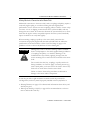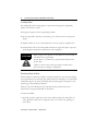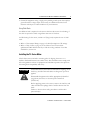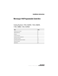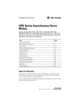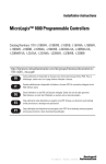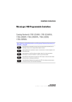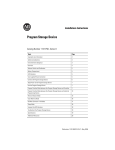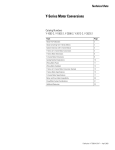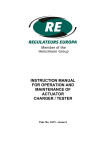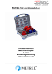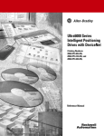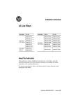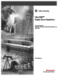
1
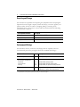
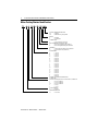
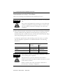
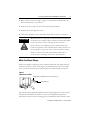
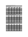
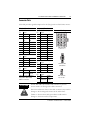
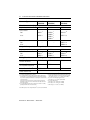
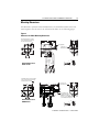
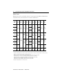
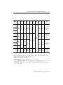
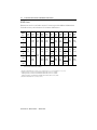
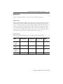
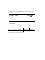
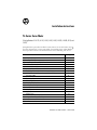
Installation Instructions
TL-Series Servo Motor
(Catalog Numbers TL-A110, -A120, -A130, -A220, -A230, -A2530, -A2540, A310, and
-A410)
This publication provides installation instructions for the TL-Series motors.
Use this document if you are responsible for installing these Allen-Bradley®
motor products. Please read all instructions before installing this motor.
For:
Receiving and Storage
Environmental Ratings
Operating Temperature and Shaft Materials
Motor Catalog Number Identification
Before You Install the Motor
Motor Installation and Maintenance Guidelines
Prolonging Motor Life
Making Mechanical Connection to the Motor Shaft
Installing Cables
Preventing Electrical Noise
Using Shaft Seals
Installing the TL-Series Motor
Motor Load Force Ratings
Connector Data
Mounting Dimensions
Metric Frame
NEMA Frame
Removing and Installing a Shaft Key
Accessories
Related Documentation
See Page
2
2
3
4
5
5
6
7
8
8
9
9
11
13
15
16
18
20
21
23
Publication TL-IN001C-EN-P — March 2005
2
TL-Series Servo Motor Installation Instructions
Receiving and Storage
The customer is responsible for inspecting the equipment before accepting the
shipment from the freight company. Check the item(s) you receive against your
purchase order. Notify the carrier of shipping damage or missing items
immediately. Store your motor in a clean and dry location within the following
environmental conditions:
Environmental Condition
Description
Storage Temperature
-10° to 85° C (14° to 185° F)
Relative Humidly
20% to 85% non-condensing
Atmosphere
non-corrosive
Environmental Ratings
The TL-Series motors, connectors, and flying leads are separately rated for
environmental protection per Ingress Protection standards (IP ratings).
TL-Series Motor
Rating Description 1
Motor with optional shaft seal 2
IP65
dust tight, water jets
Motor without a shaft seal, and
the mounted in the direction:
shaft down
shaft horizontal
shaft up
IP53
IP51
IP50
dust protected, spraying water
dust protected, vertically falling water
dust protected, no special moisture protection
Flying leads and connectors
IP30
protected from objects greater than 12.5 mm (0.5 in.)
in diameter, no special moisture protection
1 IP rating descriptions are for reference only. Refer to the international standards for more complete rating descriptions.
2 An optional shaft seal kit is required to provide the IP65 rating. See Accessories on page 21.
Publication TL-IN001C-EN-P — March 2005
TL-Series Servo Motor Installation Instructions
3
Operating Temperature and Shaft Materials
Condition or Material
Description
Operating Temperature
0° to 40° C (32° to 104° F)
Shaft Material
carbon steel
Shaft Key Material
carbon steel
Publication TL-IN001C-EN-P — March 2005
4
TL-Series Servo Motor Installation Instructions
Motor Catalog Number Identification
TL - A 4 10 M - B J 3 2 AA
FACTORY DESIGNATED OPTIONS
AA
= Standard
AN
= NEMA Mounting Flange/Shaft
BRAKE
2
= No Brake
4
= 24VDC Brake
CONNECTORS
3
= Flying Leads with Connectors
ENCLOSURE/SHAFT KEY/SHAFT SEAL
J
= IP65 Housing/Shaft Key/No Shaft Seal
K
= IP65 Housing/No Shaft Key/No Shaft Seal
FEEDBACK
B
= Absolute Encoder, Battery-backed Multi-turn
H
= Incremental Encoder (2000 lines)
RATED SPEED
A
= 500 rpm
B
= 1000 rpm
C
= 1500 rpm
D
= 2000 rpm
E
= 2500 rpm
F
= 3000 rpm
G
= 3250 rpm
H
= 3500 rpm
J
= 3750 rpm
K
= 4000 rpm
L
= 4250 rpm
M
= 4500 rpm
N
= 4750 rpm
P
= 5000 rpm
Q
= 5250 rpm
R
= 5500 rpm
S
= 5750 rpm
T
= 6000 rpm
MAGNET STACK LENGTH DESIGNATOR
FLANGE SIZE
Diameter of Mounting Bolt Circle for Metric Motors, or NEMA size
1
= 46 mm or NEMA 17
2
= 70 mm or NEMA 23
25
= 90 mm or NEMA 34
3
= 100 mm
4
= 115 mm
VOLTAGE RATING
A
= 230 VAC
SERIES DESIGNATOR
TL
= Low Inertia
Publication TL-IN001C-EN-P — March 2005
TL-Series Servo Motor Installation Instructions
5
Before You Install the Motor
1. Remove the motor carefully from its shipping container.
2. Visually inspect the motor for any damage.
3. Examine the motor frame, front output shaft, and mounting pilot for any
defects.
4. Notify the carrier of any shipping damage immediately.
ATTENTION
!
Do not attempt to open and modify the motor. Modifications
that can be performed in the field are described in this manual,
other changes should not be attempted.
Only a qualified Allen-Bradley employee can service this type
of motor.
Failure to observe these safety procedures could result in
personal injury, damage to equipment, and void warranty
coverage.
Motor Installation and Maintenance Guidelines
The following sections provide general installation and maintenance information.
The information should assist you to correctly install and to provide maintenance
that will prolong the lifetime of your TL servo motor.
ATTENTION
!
Ensure that cables are installed and restrained to prevent
uneven tension or flexing at the cable connectors.
Excessive and uneven force at the cable connectors may result
in damage to the connector housings and contacts as the cable
flexes.
Failure to observe these safety procedures could result in
damage to the motor and its components.
Publication TL-IN001C-EN-P — March 2005
6
TL-Series Servo Motor Installation Instructions
Prolonging Motor Life
Thoughtful design and proper maintenance can increase the life of a servo motor.
The following are guidelines to maximize the life of a servo motor.
• Always provide a drip loop in each cable to carry liquids away from connections.
• If design requirements permit, provide shields that protect the motor housing,
shaft seals, and their junctions from product contamination and fluids.
• Inspect the motor and seals for damage or wear at 6-month intervals. Replace
damaged items.
A dry and dusty environment will cause a seal to wear more rapidly than a wet or
oily environment. However, fluids can be forced around worn seals more easily
than dry particles. Replace a shaft seal at or before its expected lifetime, as
bearing contamination significantly shortens the life of a servo motor.
• Brakes on these servo motors are holding brakes. The brakes are spring-set, and
release when voltage is applied to the brake coil. A separate power source is
required to disengage the brake. This power source may be applied by a servo
motor controller, in addition to manual operator control.
The recommended method of preventing shaft rotation is:
1. Command the servo drive to 0 rpm.
2. Verify the motor is at 0 rpm.
3. Engage the brake.
4. Disable the drive.
Disabling the drive removes the potential for brake wear caused by a poorly
tuned servo system oscillating the shaft.
If system main power fails, holding brakes can withstand occasional use as
stopping brakes. This situation allows some shaft rotation as the braking occurs,
and also may create mechanical backlash within the system. Braking with power
applied to the motor is potentially damaging to the system, increases brake wear,
and reduces brake life.
IMPORTANT
Holding brakes are not designed to stop rotation of the
motor shaft, nor are they intended to be used as a safety
device. They will hold a motor shaft at 0 rpm for up to the
rated brake holding torque.
Publication TL-IN001C-EN-P — March 2005
TL-Series Servo Motor Installation Instructions
7
Making Mechanical Connection to the Motor Shaft
Mechanical connections to the motor shaft, such as couplings and pulleys, require a
torsionally rigid coupling or a reinforced timing belt. The high dynamic
performance of servo motors can cause couplings, pulleys or belts to loosen or slip
over time. A loose or slipping connection will cause system instability and may
damage the motor shaft. All connections between the system and the servo motor
shaft must be rigid to achieve acceptable response from the system. Periodically
inspect connections to verify their rigidity.
When mounting couplings or pulleys to the motor shaft, ensure that the
connections are properly aligned and that axial and radial loads are within the
specifications of the motor. Refer to Motor Load Force Ratings on page 11 for
guidelines on how to achieve 20,000 hours of motor bearing life.
ATTENTION
!
Damage may occur to the motor bearings and the feedback
device if sharp impact to the shaft is applied during installation
of couplings and pulleys, or a shaft key. Damage to the
feedback device may result by applying leverage from the
motor mounting face to remove devices mounted on the motor
shaft.
Do not strike the shaft, key, couplings, or pulleys with tools
during installation or removal. Apply a constant pressure (e.g.,
with a wheel puller) to the user end of the shaft to remove any
friction fit or stuck device from the motor shaft.
Failure to observe these safety procedures could result in
damage to the motor and its components.
A shaft key provides a rigid mechanical connection with the potential for
self-alignment, but the key must be properly installed in the keyway. Refer to:
• Mounting Dimensions on page 15 for dimensional information about the key and
shaft keyway, and
• Removing and Installing a Shaft Key on page 20 for recommendations on how to
remove and install a shaft key.
Publication TL-IN001C-EN-P — March 2005
8
TL-Series Servo Motor Installation Instructions
Installing Cables
Knowledgeable cable routing improves system electromagnetic compatibility
(EMC). To install the cables:
1. Keep wire lengths as short as physically possible.
2. Route signal cables (encoder, serial, analog, etc.) away from motor and power
wiring.
3. Separate cables by 0.3 m (1 ft) minimum for every 9 m (30 ft) of parallel run.
4. Ground both ends of the cable shield and twist the signal wire pairs to prevent
electromagnetic interference (EMI) from other equipment.
ATTENTION
!
High voltage can be present on the shields of a power cable, if
the shields are not grounded.
Ensure there is a connection to ground for all shields in the
power cable.
Failure to observe these safety procedures could result in
personal injury or damage to equipment.
Preventing Electrical Noise
Electromagnetic interference (EMI), commonly called noise, may adversely impact
motor performance by inducing stray signals. Effective techniques to counter EMI
include filtering the AC power, shielding and separating signal carrying lines, and
practicing good grounding techniques.
Effective AC power filtering can be achieved by using isolated AC power
transformers or properly installed AC line filters.
To help avoid EMI:
• Physically separate signal lines from motor cabling and power wiring. Do not
route signal wires with motor and power wires, or over the vent openings of
servo drives.
Publication TL-IN001C-EN-P — March 2005
TL-Series Servo Motor Installation Instructions
9
• Ground all equipment using a single-point parallel ground system that employs
ground bus bars or large straps. If necessary, use additional electrical noise
reduction techniques to reduce EMI in noisy environments.
Using Shaft Seals
An additional seal is required on the motor shaft near the motor front bearing, if
the shaft is exposed to fluids or significant amounts of fine dust.
An IP65 rating for the motor, exclusive of flying leads, requires the use of shaft
seals.
• Refer to Environmental Ratings on page 2 for brief descriptions of IP ratings.
• Refer to Shaft Seal Kits on page 21 or the Motion Control Selection Guide
(publication GMC-SG001x-EN-P) to find the catalog numbers of seal kits
available for your motor.
Installing the TL-Series Motor
All TL-Series motors include a mounting pilot for aligning the motor on a
machine. Preferred fasteners are stainless steel. The installation must comply with
all local regulations and use of equipment and installation practices that promote
electromagnetic compatibility and safety.
ATTENTION
!
Unmounted motors, disconnected mechanical couplings, loose
shaft keys, and disconnected cables are dangerous if power is
applied.
Disassembled equipment should be appropriately identified
(tagged-out) and access to electrical power restricted
(locked-out).
Before applying power to the motor, remove the shaft key and
other mechanical couplings which could be thrown from the
shaft.
Failure to observe these safety procedures could result in
personal injury.
Publication TL-IN001C-EN-P — March 2005
10
TL-Series Servo Motor Installation Instructions
Recommendations on Installing TL-Series Motors
Observe the following recommendations when installing the motor.
ATTENTION
TL-Series motors are not for direct connection to an AC power
line.
!
Servo motors are designed for connection to a servo drive that
controls the application of AC power. Failure to observe these
safety procedures could result in damage to the motor and
equipment.
1. Allow sufficient clearance around motor to keep it from exceeding its maximum
operating temperature range. Refer to Receiving and Storage on page 2 for the
operating range. Do not install the motor in an area with restricted airflow. Keep
other heat producing devices away from the motor.
To obtain the specified motor thermal rating, mount the motor on a surface
with heat dissipation equivalent to an aluminum heatsink of the following
dimensions:
Motor Frame Size
Heatsink Dimensions
millimeters
inches
TL-A1xx
203.2 x 203.2 x 6.35
8 x 8 x 0.25
TL-A2xx
254.0 x 254.0 x 6.35
10 x 10 x 0.25
TL-A25xx, TL-3xx, and TL-A4xx
304.8 x 304.8 x 12.7
12 x 12 x 0.50
ATTENTION
!
Outer surfaces of motor can reach high temperatures, 125° C
(257° F) during motor operation.
Take precautions to prevent accidental contact with hot
surfaces. Locate the motor and route cable connections to avoid
contact with hot surfaces.
Failure to observe these safety procedures could result in
personal injury or damage to equipment.
Publication TL-IN001C-EN-P — March 2005
TL-Series Servo Motor Installation Instructions
11
2. Refer to Motor Load Force Ratings on page 11 to determine the radial and axial
shaft load limitations of your motor.
3. Position the motor with the cable mounts pointing downward.
4. Properly mount and align the motor.
5. Connect the feedback, power, and brake cables after the motor is mounted.
ATTENTION
!
Mount the motor so exposure to dust and liquids is minimized
for both the motor and its cable connections, and restrain cables
to prevent uneven tension or flexing at the connectors.
Short circuits in the feedback, power, or brake circuits may
result from exposure of the unsealed motor cable connectors to
dust or liquids, or by uneven forces at the connector housing.
Failure to observe these safety procedures could result in
personal injury or damage to the motor and equipment.
Motor Load Force Ratings
Motors are capable of operating with a sustained shaft load. The radial and axial
load force location is shown in the figure, and maximum values are in the tables.
Note: Loads are measured in pounds, kilograms are mathematical conversions.
Figure 1
Load Forces on Shaft
Radial load force applied at center of shaft extension
Axial load force
The following tables represent 20,000 hour L10 bearing fatigue life at various loads
and speeds. The 20,000 hour life does not account for application-specific life
reduction that may occur due to bearing grease contamination from external sources.
Publication TL-IN001C-EN-P — March 2005
12
TL-Series Servo Motor Installation Instructions
Radial Load Force Ratings
Motor
1000 rpm
2000 rpm
3000 rpm
4500 rpm
5000 rpm
kg
(lb)
kg
(lb)
kg
(lb)
kg
(lb)
kg
(lb)
11
(24)
9
(19)
7
(16)
–
–
6
(14)
TL-A120P
12
(26)
10
(21)
8
(18)
–
–
7
(15)
TL-A130P
13
(29)
10
(23)
9
(20)
–
–
8
(17)
TL-A110P
TL-A220P
27
(60)
22
(48)
19
(42)
–
–
16
(35)
TL-A230P
31
(68)
24
(54)
21
(47)
–
–
18
(40)
TL-A2530P
48
(106)
38
(84)
34
(74)
–
–
28
(62)
TL-A2540P
50
(110)
39
(87)
34
(76)
–
–
29
(64)
TL-A310M
80
(177)
64
(140)
56
(123)
47
(103)
–
–
TL-A410M
76
(168)
60
(133)
53
(117)
44
(98)
–
–
Axial Load Force Ratings (Maximum Radial Load)
Motor
1000 rpm
2000 rpm
3000 rpm
4500 rpm
5000 rpm
kg
(lb)
kg
(lb)
kg
(lb)
kg
(lb)
kg
(lb)
TL-A110P
8
(18)
6
(14)
5
(10)
–
–
4
(9)
TL-A120P
9
(20)
7
(16)
5
(12)
–
–
5
(10)
TL-A130P
10
(22)
8
(17)
6
(13)
–
–
5
(11)
TL-A220P
15
(32)
11
(24)
9
(20)
–
–
7
(16)
TL-A230P
15
(34)
12
(26)
10
(21)
–
–
8
(17)
TL-A2530P
18
(39)
13
(29)
11
(24)
–
–
9
(19)
TL-A2540P
18
(39)
13
(29)
11
(25)
–
–
9
(20)
TL-A310M
24
(54)
18
(40)
15
(34)
12
(27)
–
–
TL-A410M
29
(64)
21
(47)
18
(40)
14
(31)
–
–
Axial Load Force Ratings (Zero Radial Load)
Motor
1000 rpm
2000 rpm
3000 rpm
4500 rpm
5000 rpm
kg
(lb)
kg
(lb)
kg
(lb)
kg
(lb)
kg
(lb)
TL-A110P
12
(26)
9
(20)
7
(16)
–
–
6
(13)
TL-A120P
12
(26)
9
(20)
7
(16)
–
–
6
(13)
TL-A130P
12
(26)
9
(20)
7
(16)
–
–
6
(13)
TL-A220P
19
(41)
14
(30)
11
(25)
–
–
9
(20)
TL-A230P
19
(41)
14
(30)
11
(25)
–
–
9
(20)
TL-A2530P
23
(50)
17
(37)
14
(31)
–
–
11
(25)
TL-A2540P
23
(50)
17
(37)
14
(31)
–
–
11
(25)
TL-A310M
29
(65)
22
(48)
19
(41)
15
(32)
–
–
TL-A410M
34
(75)
25
(55)
21
(47)
17
(37)
–
–
Publication TL-IN001C-EN-P — March 2005
TL-Series Servo Motor Installation Instructions
13
Connector Data
This table provides signal descriptions for the flying leads on all TL-Series motors.
Absolute Encoder
Feedback Connector
Pin Signal
1-6 Reserved —
7
EPWR
red
8
ECOM and brown/blk
BATblk
9
SHIELD
blk shrink
10-11 Reserved —
12
SD+
blue
13
SDblue/blk
14
BAT+
brown
15
Reserved —
Power Connector
Pin Signal
1
U phase
red
2
V phase
white
3
W phase black
4
Ground
yellow/grn
Brake Connector
Pin Signal
1
BR+
yellow
2
BRblue
-A410 only yellow
See page 14 for additional
information about these
AMP™ connectors.
ATTENTION
!
Incremental Encoder
Feedback Connector
Connector Housings
Pin Signal
6
1
11
1
A+
green
2
Agreen/blk
7
2
12
3
B+
blue
8
3
13
4
Bblue/blk
9
4
14
5
I+
yellow
10
5
15
6
S1
gray/blk
7
+5V DC
red
AMP HOUSING
8
ECOM
black
P/N 172171-1
9
SHIELD
blk shrink
10
Iyellow/blk
11
S2
brown/blk
1
12-14 Reserved —
2
3
15
S3
white/blk
4
Power Connector
Pin Signal
AMP HOUSING
1
U phase
red
P/N 350779-1
2
V phase
black
3
W phase white
4
Ground
yellow/grn
1
Brake Connector
2
Pin Signal
AMP HOUSING
1
BR+
yellow
P/N 172165-1
blue
2
BR-A410 only yellow
Ensure that cables are installed and restrained to prevent
uneven tension or flexing at the cable connectors.
Excessive and uneven force at the cable connector may result in
damage to the housing and contacts as the cable flexes.
Failure to observe these safety procedures could result in
damage to the motor and its components.
Publication TL-IN001C-EN-P — March 2005
14
TL-Series Servo Motor Installation Instructions
Connector Type
Feedback
(15 Position)
Brake
(2 Position)
Power
(4 Position)
172171-1
172165-1
350779-1
Reel
770835-1 5
350218-3 10
Loose
794059-1 5
170359-1 7
170360-1 8
170363-1 7
170364-1 8
Motor Connectors (on flying leads):
Plug Housing
Power Contacts 1
Ground Contacts 2
Reel
Loose
—
—
350547-3 10
350654-1 10
350669-1 10
Compatible Receptacles (on mating cables):
Cap (receptacle) Housing
172163-1
172157-1
350780-1
Socket Contacts
Reel
Loose
170361-1 6
170365-1 6
170362-1 9
170366-1 9
350536-3 10
350550-3 10
Tooling (Motor Connectors and/or Compatible Receptacles):
Hand Crimp Tool
for Motor Connectors
90870-1
90758-1
Hand Crimp Tool
for Compatible Receptacles
90758-1
90759-1
Contact Extraction Tool 3
189727-1
Contact Insertion Tool 4
455830-1
1 For U, V, W in Power connector.
2 For Motor Frame GND in Power connector.
3 The locking/retention tangs on pin and socket contacts may become
deformed by use of the Contact Extraction Tool. Ensure that the tangs
are positioned slightly outward before re-inserting the contact into the
connector housing.
After contacts are inserted into the connector housing, gently pull
backward on each wire to ensure that contacts are fully seated and
latched into position.
4 Use of the Contact Insertion Tool is optional, as contacts are readily
pushed by hand into the connector housing.
Note: AMP specifies wire sizing in AWG, mm2 is a conversion from AWG.
Publication TL-IN001C-EN-P — March 2005
90546-1
318851-1
5 Wire range 0.05 - 0.14 mm2 (30-26 AWG)
6 Contacts and AWG in Rockwell manufactured cables may
vary by cable conductor. For reference only, the wire range
of the above contacts is 0.14 - 0.34 mm2 (26-22 AWG).
7 Used on TL-A1xx through TL-A25xx motors
Wire range is 0.14 - 0.34 mm2 (26-22 AWG)
8 Used on TL-A4xx motors.
Wire range 0.34 - 0.75 mm2 (22-18 AWG)
9 Wire range 0.34 - 0.75 mm2 (22-18 AWG)
10Wire range 0.50 - 2.5 mm2 (20-14 AWG)
TL-Series Servo Motor Installation Instructions
15
Mounting Dimensions
The dimension symbols and actual dimensions for the different frame sizes and
stack lengths in the TL motors are referenced in tables on the following pages.
Figure 2
References for Motor Mounting Dimensions
Mounting pattern has two holes
for A110 through A130 (shown).
All others have four holes.
L
LB
P
N
NB
L-LB
T
TB
Key (supplied)
S dia. holes on
M dia. bolt circle
D
HD
AD
LE
LA
BE
Connector
for Brake
option
only
CAB
Motor Dimensions for
Metric Frame
F
G
Mounting pattern has two threaded
holes for A120 and A130 (shown).
All others have four holes.
AC
LB
L-LB
T
D
HD
AD
LA
LE
BE
Motor Dimensions for
NEMA Frame
P
N
S dia. holes on
M dia. bolt circle
L
Key supplied with
TL-A2xx and -A25xx
(NEMA 23 and 34) only.
TL-A120 or -A130 (NEMA 17)
is not available with key slot.
CAB
F
G
Publication TL-IN001C-EN-P — March 2005
16
TL-Series Servo Motor Installation Instructions
Metric Frame
Dimensions are for non-brake motors. Footnotes provide additional dimensions
for brake motors, and tolerances for common dimensions.
Motor
Series
TL-A
AD
mm
(in.)
BE
mm
(in.)
D1
mm
(in.)
HD
mm
(in.)
31.1
(1.22)
21.0
(0.83)
8.0
(0.315)
51.1
(2.01)
130
220
12.0
(0.472
4)
43.0
(1.69)
230
2530
L-LB 3
mm
(in.)
LA
mm
(in.)
53.0
(2.09)
27.6
(1.09)
16.0
(0.629
9)
2540
310
56.0
(2.20)
410
67.0
(2.64)
38.4
(1.51)
22.0
(0.87)
73.0
(2.87)
93.0
(3.66)
84.5
(3.33)
LB 2
mm
(in.)
mm
(in.)
25.0
(0.984)
5.0
(0.20)
39.1
(1.54)
46.0
(1.811)
42.8
(1.69)
70.0
(2.76)
43.8
(1.72)
90.0
(3.54)
144.2
(5.68)
57.1
(2.25)
100.0
(3.94)
176.0
(6.93)
102.0
(4.02)
115.0
(4.53)
59.5
(2.34)
73.5
(2.89)
106.1
(4.18)
76.1
(3.00)
30.0
(1.181)
6.0
(0.24)
99.0
(3.90)
179.2
(7.06)
117.0
(4.61)
216.0
(8.50)
98.1
(3.86)
99.7
(3.93)
134.7
(5.30)
143.7
(5.66)
M
mm
(in.)
98.5
(3.88)
128.1
(5.04)
LE 2
53.5
(2.11)
78.5
(3.09)
110
120
L2
mm
(in.)
35.0
(1.378)
40.0
(1.57)
8.0
(0.32)
17. 0
(0.67)
108.7
(4.28)
NOTE: Metric motor frames are designed to metric dimensions. Inch dimensions are a mathematical conversion.
1 Tolerance for this dimension is: TL-A1xx -0.009 mm (-0.0004 in.); TL-A2xx -0.011 mm (-0.0004 in.); TL-A25xx -0.011 mm (-0.0004 in.);
TL-A310 -0.011 mm (-0.0004 in.); TL-A410 -0.013 mm (-0.0005 in.).
2 If ordering a TL-A110, TL-A120, or TL-A130 motor with brake, add 35.6 mm (1.40 in.) to L, LB, and LE.
If ordering a TL-A220, or TL-A230 motor with brake, add 34.6 mm (1.36 in.) to L, LB, and LE.
If ordering a TL-A2530, or TL-A2540 motor with brake, add 36.6 mm (1.44 in.) to L, LB, and LE.
If ordering a TL-310 motor with brake, add 23.0 mm (0.90 in.) to L, LB, and LE.
If ordering a TL-410 motor with brake, add 32.0 mm (1.26 in.) to L, LB, and LE.
3 Tolerance for this dimension is: ±1.0 mm (±0.039 in.)
Publication TL-IN001C-EN-P — March 2005
TL-Series Servo Motor Installation Instructions
Motor
Series
TL-A
N4
NB
P
S5
T
TB
mm
(in.)
mm
(in.)
mm
(in.)
mm
(in.)
mm
(in.)
mm
(in.)
30.0
(1.1811)
20.0
(0.79)
40.0
(1.57)
4.5
(0.177)
2.5
(0.10)
4.5
(0.18)
50.0
(1.9685)
27.0
(1.06)
60.0
(2.36)
5.5
(0.217)
CAB6
mm
(in.)
17
G7
F8
Key 9
mm
(in.)
mm
(in.)
mm
(in.)
110
120
3 x 3 x 15
6.2
3.0
(0.118 x 0.118 x
(0.244) (0.118)
0.59)
130
220
300
(11.8)
230
2530
70.0
(2.7556)
2540
310
410
34.0
(1.34)
80.0
(3.15)
95.0
(3.74)
80.0
(3.15)
3.0
(0.12)
4 x 4 x 15
9.5
4.0
(0.158 x 0.158 x
(0.374) (0.157)
0.59)
7.0
(0.28)
5 x 5 x 20
13.0
5.0
(0.197 x 0.197 x
(0.512) (0.197)
0.79)
6.6
(0.260)
86.0
(3.39)
—
100.0
(3.94)
9.0
(0.354)
7.0
(0.28)
—
8 x 7 x 25
18.0
8.0
(0.315 x 0.276 x
(0.709) (0.315)
0.985)
NOTE: Metric motor frames are designed to metric dimensions. Inch dimensions are a mathematical conversion.
4 Tolerance for this dimension is: TL-A1xx -0.021 mm (-0.0008 in.); TL-A2xx -0.025 mm (-0.001 in.); TL-A25xx -0.03 mm (-0.0012 in.);
TL-A310 -0.03 mm (-0.0012 in.); TL-A410 -0.035 mm (-0.0014 in.).
5 TL-A1xx has 2 mounting holes, TL-A2xx through TL-A410 have 4 mounting holes.
Mounting holes are S diameter on M diameter bolt circle.
6 Tolerance for cable length is ±50.0 mm (±1.97 in.). Minimum bend radius is 15.00 mm (0.59 in.).
7 Tolerance for this dimension is: -0.20 mm (-0.008 in.).
8 Tolerance for this dimension is: TL-A1xx -0.006 to -0.031 mm (-0.0002 to -0.0012 in.); TL-A2xx and -A25xx -0.012 to -0.042 mm (-0.0005 to
-0.0017 in.); TL-A310 -0.012 to -0.042 mm (-0.0005 to -0.0017 in.); TL-A410 -0.015 to -0.051mm (-0.0006 to -0.0020 in.).
9 Tolerance for x and y dimensions is: TL-A1xx -0.025 mm, TL-A2xx -0.030 mm, TL-A25xx -0.030 mm, TL-A3xx -0.030 mm, and TL-A410
-0.036 mm, length is untoleranced.
Publication TL-IN001C-EN-P — March 2005
18
TL-Series Servo Motor Installation Instructions
NEMA Frame
Dimensions are for non-brake motors. Footnotes provide additional dimensions
for brake motors, and tolerances for common dimensions.
Motor
Series
TL-A
120
AC
mm
(in.)
AD
mm
(in.)
BE
mm
(in.)
D1
mm
(in.)
HD
mm
(in.)
L2
mm
(in.)
L-LB 3
mm
(in.)
91.5
(3.603)
130
27.0
105.5 (1.063)
(4.153)
220
137.9
(5.43)
—
60
(2.36)
31.10
(1.22)
6.35
(0.25)
12.70
(0.50)
43.0
(1.69)
230
2530
21.0
(0.83)
52.0
(2.05)
73.0
(2.87)
27.6
(1.09)
—
53.0
(2.09)
15.875
(0.625)
2540
96.0
(3.78)
159.9
(6.30)
149.2
(5.872)
38.1
(1.50)
44.5
158.2 (1.752)
(6.205)
LA
mm
(in.)
5.0
(0.20)
6.0
(0.24)
8.0
(0.32)
LB 2
mm
(in.)
64.5
(2.54)
78.5
(3.09)
99.8
(3.93)
121.8
(4.80)
104.7
(4.12)
113.7
(4.48)
LE 2
mm
(in.)
39.1
(1.54)
43.8
(1.725)
43.3
(1.70)
66.7
(2.625)
43.8
(1.72)
98.4
(3.875)
NOTE: NEMA motor flanges and shafts are designed to inch dimensions. Other frame areas are designed to metric dimensions.
Conversions are mathematically calculated.
1 Tolerance for this dimension is: TL-A1xx -0.009 (-0.0004); TL-A2xx -0.011 (-0.0004); TL-A25xx -0.011 (-0.0004).
2 If ordering a TL-A120, or TL-A130 motor with brake, add 35.6 mm (1.40 in.) to L, LB, and LE.
If ordering a TL-A220, or TL-A230 motor with brake, add 34.6 mm (1.36 in.) to L, LB, and LE.
If ordering a TL-A2530, or TL-A2540 motor with brake, add 36.6 mm (1.44 in.) to L, LB, and LE.
3 Tolerance for this dimension is: ±1.0 mm (±0.039 in.).
Publication TL-IN001C-EN-P — March 2005
M
mm
(in.)
TL-Series Servo Motor Installation Instructions
Motor
Series
TL-A
120
N4
NB
P
S5
T
19
G7
F8
Key 9
mm
(in.)
mm
(in.)
mm
(in.)
mm
(in.)
TB
CAB 6
mm
(in.)
mm
(in.)
mm
(in.)
mm
(in.)
mm
(in.)
mm
(in.)
22.0
(0.8661)
—
42.0
(1.65)
8-32
Thread
2.0
(0.08)
—
300
(11.8)
—
—
—
38.1
(1.50)
—
56.4
(2.22)
5.5
(0.217)
1.5
(0.06)
—
300
(11.8)
10.92
(0.43)
3.175
(0.125)
(0.125 x 0.125
x 0.9375)
73.02
(2.875)
—
86.0
(3.39)
5.5
(0.217)
1.6
(0.06)
—
300
(11.8)
13.13 4.763 (0.187 x 0.187
(0.517) (0.1875)
x 1.156)
130
220
230
2530
2540
NOTE: NEMA motor flanges and shafts are designed to inch dimensions. Other frame areas are designed to metric dimensions.
Conversions are mathematically calculated.
4 Tolerance for this dimension is: TL-A1xx -0.021 mm (-0.0008 in.); TL-A2xx -0.025 mm (-0.001 in.); -A25xx -0.03 mm (-0.0012 in.);.
5 TL-A1xx has 2 threaded holes, TL-A2xx and TL-A25xx have 4 mounting holes.
Mounting holes are S diameter on M diameter bolt circle.
6 Tolerance for cable length is ±50.0 mm (±1.97 in.). Minimum bend radius is 15.00 mm (0.59 in.).
7 Tolerance for this dimension is: -0.38 mm (-0.015 in.).
8 Tolerance for this dimension is: +0.051 mm (+0.002 in.)
9 Tolerance for x and y dimensions is: (-0.002 in.), length is untoleranced.
Publication TL-IN001C-EN-P — March 2005
20
TL-Series Servo Motor Installation Instructions
Removing and Installing a Shaft Key
TL shaft keys are constructed of carbon steel. Keys for metric mount motors are
toleranced for interference fit (slightly larger than the opening) to ensure a secure
and rigid fit for the mating connection. Keys for NEMA mount motors are
toleranced for a slightly loose (slip) fit.
ATTENTION
!
Damage may occur to the motor bearings and the feedback
device if sharp impact to the shaft is applied during installation
of couplings and pulleys, or a shaft key. Damage to the feedback
device may result by applying leverage from the motor
mounting face to remove devices mounted on the motor shaft.
Failure to observe these safety procedures could result in
damage to the motor and its components.
To remove an interference fit key:
• Lift the key by grasping it with a plier or similar tool.
• Lever the key with a flat blade screwdriver inserted between the key and the slot.
To install an interference fit key:
• Verify the replacement key matches the keyway in the shaft and the mating
mechanical connection (e.g., coupling or pulley) before proceeding.
• Support the underside of the shaft diameter with a fixture (Figure 3), and use a
controlled press device to apply a constant force across the top surface to press
the key into the shaft.
Figure 3
Key Alignment and Shaft Support
Shaft
Support for shaft
and/or motor
Publication TL-IN001C-EN-P — March 2005
TL-Series Servo Motor Installation Instructions
21
Accessories
Factory available accessories for the TL motors are described below.
Motor Cables
Factory manufactured feedback, brake, and power cables are available in standard
cable lengths. Transition cables are available to allow connection of a TL-Series
motor to existing N-Series or Y-Series power, feedback, and brake cables. Factory
cables provide proper shield termination which reduces the potential for EMI.
For a complete listing of available cables refer to your drive’s installation manual,
contact your nearest Rockwell Automation sales office, or access the information
from the web sites referenced in Related Documentation on page 23.
Shaft Seal Kits
Catalog numbers and dimensions for TL shaft seals are shown below.
Motor
Catalog Number 1 Inside Diameter Outside Diameter Width
mm
(in.)
mm
(in.)
mm
(in.)
TL-A110,
TL-A120,
TL-A130
TL-SSN-1
8.9
(0.35)
16
(0.71)
3
(0.12)
TL-A220,
TL-A230
TL-SSN-2
14.0
(0.55)
24
(0.95)
5
(0.20)
TL-A2530,
TL-A2540,
TL-A310
TL-SSN-3
19.8
(0.78)
30
(1.18)
5
(0.20)
TL-A410
TL-SSN-4
24.0
(0.95)
40
(1.57)
10
(0.39)
1 Shaft seals require a lubricant to reduce wear. Lubricant is provided with kit.
Publication TL-IN001C-EN-P — March 2005
22
TL-Series Servo Motor Installation Instructions
Transition Plates
Transition plates allow a TL-Series NEMA motor to physically replace N-Series
motors.
Compatible Motors
Catalog Number
Description
N-Series
TL-Series
NEMA
TL-TRPLAT-17-23
TL-Series Transition Plate, NEMA 17 to 23
N-23xx
TL-A1xxP-xxxxN
TL-TRPLAT-23-34
TL-Series Transition Plate, NEMA 23 to 34
N-34xx
TL-A2xxP-xxxxN
TL-TRPLAT-34-42
TL-Series Transition Plate, NEMA 34 to 42
N-42xx
TL-A25xxP-xxxxN
Transition plates are not available for the N-56xx motors.
Transition Cables
Transition cables interface between existing N-Series and Y-Series motor cables
and the flying lead cables on TL-Series motors with incremental encoders.
Motor Type
Cable Length
Feedback Cable
Power Cable
Brake Cable
N-Series
305 mm (12.0 in.)
2090-XXNFTN-S 1
2090-XXNPTN-16S 1
2090-XXNBTN-S 1
Y-Series
610 mm (24.0 in.)
2090-XXNFTY-S 1
2090-XXNPTY-16S 1, 2
1. Transition cables are only for use on TL-Series motors with incremental encoders.
2. Y-Series transition cables have Power and Brake connections combined in one cable.
Publication TL-IN001C-EN-P — March 2005
TL-Series Servo Motor Installation Instructions
23
Related Documentation
These publications provide additional information; specifically about TL motors
and compatible Rockwell Automation drives. To obtain a copy, contact your local
Rockwell Automation office or distributor, or access the documents on-line at
http://www.rockwellautomation.com/literature.
For information about:
Read this document:
Publication Number
Connecting to Ultra1500™
Digital Servo Drives
Quick Start Instructions
User Manual
2092-QS001x-EN-P
2092-IN001x-EN-E
Connecting to Ultra3000™
Digital Servo Drives
Installation Manual
Integration Manual
2098-IN003x-EN-P
2098-IN005x-EN-P
Connecting to Kinetix® 6000
Multi-Axis Servo Drives
Installation Manual
Integration Manual
2094-IN001x-EN-P
2094-IN002x-EN-P
TL-Series Motor Transition Plates
Installation Instructions
TL-IN001x-EN-P
A glossary of industrial automation terms Allen-Bradley Industrial
and abbreviations
Automation Glossary
AG-7.1
How to minimize and control
system-level noise.
System Design for Control
of Electrical Noise
Reference Manual
GMC-RM001x-EN-P
An overview of Allen-Bradley motion
controls and systems, including
information about the this and other
motors.
Motion Control Selection
Guide
GMC-SG001x-EN-P
Publication TL-IN001C-EN-P — March 2005
For more information refer to our web site: www.ab.com/motion
For Rockwell Automation Technical Support information refer to: www.ab.com/support or Tel: (1) 440.646.5800
Allen-Bradley and Kinetix are registered trademarks of Rockwell Automation, Inc.
Ultra1500 and Ultra3000 are registered trademarks of Rockwell Automation, Inc.
AMP and TYCO are trademarks of Tyco International, Ltd.
Publication TL-IN001C-EN-P — March 2005
Supersedes publication TL-IN001B-EN-P — December 2004
PN 0013-2067-001-03
Copyright © 2005 Rockwell Automation, Inc. All rights reserved. Printed in the USA.