1
ColumbiaUniversity Center
for Computing Activities
Terminal and Plotter
User Manual
(
Janet F. Asteroff
lJserServkesC;roup
(
(
Copyright IC) 1982 Columbia University Center For Computing Activities
(
Table of Contents
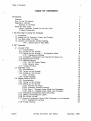
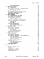
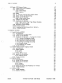
TABLE OF CONTENTS
Introduction
1
Overview
How To Use This Manual
Selecting A Terminal
Summary of Terminals
Notes For New Users
Using a Computer Terminal For the First Time
A Helpful Comparison
1
1
2
2
4
4
4
1. The First Step In Using The Computer
1.1.
1.2.
1.3.
1.4.
5
Procedures
Setting Up The Terminal In Theory and Practice
Two Basic Rules To Follow
Common and Important Terminal Settings
1.4.0.1. Special Note on Baud Rates
5
5
6
6
7
2. CRT Terminals
(
8
2. 1. Concept-APL8
2. 1. 1. Documentation
2.1.2. Turning on the Terminal
2.1.3. Setting Up the Terminal -- Configuration Mode
2. 1.3. 1. Changing the Settings
2.1.4. Completing Configuration and Clearing the Status Line
2.1.5. Resetting the Terminal
2.1.6. Optional Features
2.1.6.1. 80/132 Column Display
2.1.6.2. Reverse Video
2.1.7. Trouble-shooting
2.2. Datamedia 1520
2.2. 1. Documentation
2.2.2. Turning on the Terminal
2.2.3. Setting Up the Terminal
2.2.3.1. Switches
2.2.4. Trouble-shooting
2.3. Hewlett-Packard 2621A
2.3. 1. Documentation
2.3.2. Turning on the Terminal
2.3.3. Setting Up the Terminal
2.3.3.1. Function Key Group
2.3.3.2. Executing Terminal Functions
2.3.3.3. Step l--Changing Upper Mode Line Parameters
2.3.3.4. Step 2--Changing Lower Mode Line Parameters
2.3.4. Completing Configuration Mode and EXiting
2.3.5. Clearing and Recalling the Labels
2.3.6. The Column Counter
2.3.7. Entering Configuration Mode While Connected to the Computer
2.3.7.1. Resetting the Terminal
2.3.8. Trouble-shooting
CUCCA
Terminal And Plotter User Manual
8
8
8
8
11
12
12
12
12
13
13
14
14
14
15
15
16
17
18
18
19
19
19
20
22
22
23
23
23
23
24
November. 1982
Table of Contents
Ii
2.3.8.1. Special Problems
2.4. Hewlett-Packard National
2.4.1. Documentation
2.4.2. Setting Up the Terminal -- Configuration Mode
2.4.2.1. Changing the Straps
2.4.2.2. Lower Mode Line
2.4.3. Language Mode
2.4.4. Completing Configuration Mode and EXiting
2.4.5. Clearing and Recalling the Labels
2.4.6. Resetting the Terminal
2.5. Intertec SuperBrain
2.5.1. Documentation for File Transfer
2.5.2. Usage Policy and Scheduling
2.5.3. Operating the SuperBrain
2.5.3.1. Turning on the Terminal
2.5.3.2. Interrupting the Program
2.5.4. Using the SuperBrain as an ASCII Terminal
2.5.5. Using Floppy Disks with the SuperBrain
2.5.5.1. DEC-20
2.5.5.2. IBM
2.5.6. Notes on Floppy Disks
2.5.6.1. Storage Capacity
2.5.6.2. Purchase of Floppy Disks
2.6. Perkin-Elmer 1100
2.6.1. Documentation
2.6.2. Turning on the Terminal
2.6.3. Setting Up the Terminal
2.6.3.1. Switches
2.6.3.2. Configuration Buttons
2.6.4. Completing Configuration
2.6.5. Trouble-shooting
2.7. VT101
2.7. 1. Documentation
2.7.2. Turning on the Terminal
2.7.3. Setting Up the Terminal -- Set Up Modes A and B
2.7.3.1. Set-Up Mode A
2.7.3.2. Exiting Set-Up Mode A
2.7.3.3. Set-Up Mode B
2.7.3.4. Exiting Set-Up Mode B
2.7.4. Resetting the Terminal
2.7.5. Optional Features
2.7.5.1. 80/132 Column Display
2.7.5.2. Reverse Video
2.7.6. Trouble-shooting
24
25
25
26
26
26
27
27
27
27
28
29
29
29
29
29
30
30
30
31
31
32
32
33
33
33
34
34
36
36
37
38
38
38
39
39
39
39
40
40
41
41
41
42
(
(
43
3. Hardcopy Terminals
3. 1. DECwriter LA36 Matrix Printer
3. 1. 1. Documentation
3.1.2. Paper
3.1.3. Turning on the Terminal
3.1.4. Setting Up the Terminal
3.1.5. Trouble-shooting
43
43
45
45
45
46
(
CUCCA
Terminal And Plotter User l\IIanual
November, 1982
iii
Table of Contents
3.2. Diablo 1620 Hyterm Printer
3.2.1. Usage Policy and Scheduling
3.2.2. Diablo Supplies
3.2.2.1. Print Wheels
3.2.2.2. Ribbons
3.2.3. Paper
3.2.4. An Important Warning About Diablo Usage
3.2.5. Before Turning on the Terminal
3.2.6. Setting Up the Terminal
3.2.6.1. Inside Control Panel
3.2.7. Changing the Baud Rate
3.2.8. Turning on the Terminal
3.2.8.1. Right Control Panel--Red Rocker Switches
3.2.8.2. Left Control Panel
3.2.9. Impression Control Switch
3.2, 10. Printer Controls
3.2.11. Resetting the Terminal and Error Recovery
3.2,12. Trouble-shooting
4. Graphics Terminals
55
4.1. Hewlett-Packard 2623A
4.1. 1. Documentation
4.1.2. A Special Note on Baud Rates
4.1.3, Turning on the Terminal
4.1.4, Setting Up the Terminal -- Configuration Modes
4.1.4,1. Terminal Configuration Mode
4.1.4.2, Saving the Settings and Exiting
4.1.4,3. Datacomm Configuration Mode
4.1.4.4. Saving the Settings and Exiting
4.1.4,5. Graphics Mode
4. 1.4.6. Resetting the Terminal
4.1.5. Trouble-shooting
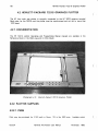
4.2. Hewlett-Packard 7221 S Graphics Plotter
4.2.1. Documentation
4.2.2. Plotter Supplies
4.2.2.1. Pens
4.2.2.2, Paper
4.2.3. Turning on the Plotter
4.2.4. Setting Up the Terminal
4.2.4.1. Manual Control
4.2,5. Trouble-shooting
4.3. Tektronix 4013
4.3.1. Documentation
4.3.2. Turning On the Terminal
4.3.3. Setting Up the Terminal
4,3.3.1. Knobs
4,3.3.2, Switches
4.3.4. Clearing the Screen and Resetting the Terminal
4.3.5. Trouble-shooting
4.4. Tektronix 4631
4.4,1. Trouble-shooting
4.4.2. Graphics Software
CUCCA
47
47
48
48
48
48
48
49
49
49
51
51
51
52
52
52
53
53
Terminal And Plotter User Manual
55
56
56
56
56
57
57
57
58
58
58
59
60
60
60
60
61
61
61
62
64
65
65
66
66
66
67
67
67
68
69
69
November, 1982
iv
Table of Contents
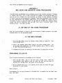
5. Terminal Repair and Installation Procedures
70
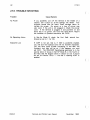
5.1. Terminal Problems
5. 1. 1. Reporting to Systems Assurance
5.2. Purchasing A Terminal
70
70
70
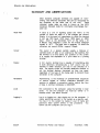
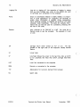
Glossary and Abbreviations
71
Appendix I. DEC WS78 and DECMATE Word Processors
73
1.1. Setting Up the Word Processor
1.2. The IBM Systems
Preparing to Log in
1.3. DEC-20 System
1.4. Returning to the Word Processor
Trouble-shooting
(
73
73
73
74
74
74
Appendix II. Solving Common Problems
75
Appendix III. HP 2621A and HP 2621 National Summary
76
Index
77
(
(
CUCCA
Terminal And Plotter User Manual
November, 1982
v
List of Photographs
LIST OF PHOTOGRAPHS
Photograph
Photograph
Photograph
Photograph
Photograph
Photograph
Photograph
Photograph
Photograph
Photograph
Photograph
Photograph
Photograph
Photograph
Photograph
Photograph
Photograph
Photograph
Photograph
Photograph
Photograph
Photograph
Photograph
Photograph
Photograph
Photograph
Photograph
Photograph
Photograph
CUCCA
2-1:
2-2:
2-3:
2-4:
2-5:
2-6:
2-7:
2-8:
2-9:
2-10:
2-11:
2-12:
2-13:
2-14:
2 - 15:
2-16:
3-1:
3-2:
3-3:
3-4:
3-5:
3-6:
4-1:
4-2:
4-3:
4-4:
4-5:
4-6:
4-7:
Concept-APL8
Concept-APL8 Keyboard
Concept APL-8 Cursor Control Pad and Numeric Pad
Datamedia 1520
Datamedia Switches
Datamedia Keyboard
Hewlett-Packard 2621A
Hewlett-Packard 2621A Keyboard
Hewlett-Packard Function Key Group
Hewlett-Packard National
I ntertec SuperBrain
Perkin-Elmer 1100
Perkin-Elmer Switches and Logo Plate
Perkin-Elmer Keyboard and Configuration Buttons
VT101
VTf01 Set-Up Card
~M
LA36 Keyboard
LA36 Switches
Diablo 1620
Diablo 1620 Keyboard
Diablo Inside and Right Control Panels
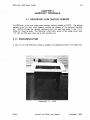
Hewlett-Packard 2623A
Hewlett-Packard 2623A Keyboard
Hewlett-Packard 7221S Graphics Plotter
Hewlett-Packard 7221S Front Control Panel
Tektronix 4013
Tektronix Knobs
Tektronix 4631
Terminal And Plotter User Manual
9
9
10
14
15
16
17
18
18
25
28
33
35
35
38
41
43
44
44
47
49
50
55
56
60
62
65
66
68
November, 1982
vi
List of Figures
LIST OF FIGURES
Figure
Figure
Figure
Figure
Figure
Figure
Figure
Figure
Figure
2-1:
2-2:
2-3:
2-4:
2-5:
2-6:
2-7:
2-8:
2-9:
Concept-APL Mode Line
Hewlett-Packard 2621A Upper Mode Line Labels
Hewlett-Packard 2621A Lower Mode Line Labels
Hewlett-Packard National Upper Mode Line Labels
Hewlett-Packard National Lower Mode Line Labels
Hewlett-Packard National Language Mode
Perkin-Elmer 1100 Settings
VT101 Set-Up Mode B--Four Left Fields
VT101 Set-Up Mode B--Three Right Fields
(
8
20
20
26
26
27
34
40
40
(
(
CUCCA
Terminal And Plotter User Manual
November, 1982
vii
List of Tables
LIST OF TABLES
Table 1-1:
Table 2-1:
CUCCA
IBM 4341 and DEC-20 Settings
Hewlett-Packard 2621A Value Settings
Terminal And Plotter User Manual
6
20
November, 1982
(
(
(
Introduction
INTRODUCTION
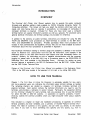
OVERVIEW
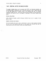
The Terminal And Plotter User Manual explains how to operate the public computer
terminals and graphics plotters made available by CUCCA (Columbia University Center for
Computing Activities). This manual will help you select the terminal which best suits your
needs, and once having done so, operate it successfully; no knowledge of computing or
computer terminals is required.
Included for those who have never used a computer
terminal before are special introductory sections as well as a glossary. For advanced users,
general technical information and terminal settings are provided for reference.
In addition to the sections on public terminals, instructions are included for using the DEC
WS78 and DECMATE word processors as ASCII terminals to connect to the IBM 3031,
4341, and DECSYSTEM-20 computers. Privately purchased, these word processors are
located in many administrative and academic offices; they are not made available by CUCCA.
Information about the word processors is presented in Appendix I.
Non-technical information relating to terminal usage and availability is detailed in the CUCCA
GUide To Research and Instructional Facilities and the Newsletter, both available in the
Reference Room in the SSIO (Self-Service Input-Output) area (see immediately below for
location). Similarly, for instructions on how to establish communications with the computer
1I0gging in), please refer to the IBM 4341 Log In Procedures sheet or the DECSYSTEM-20
Reference Card, both available in the Reference Room.
Software for setting up many
terminal features is explained in the DEC-20 Reference Card, the IBM 4341 Wylbur Manual
and the CMS Wylbur Technical Note.
Copies of the Terminal And Plotter User Manual are available in the Reference Room,
1 15A, in the SSIO area located in the basement of Uris Hall, or by calling 280-4330.
HOW TO USE THIS MANUAL
Chapter 1, The First Step In Using The Computer, is extremely valuable for new users,
and more advanced users can reference the information about terminal settings as needed
The remaining chapters are divided by category: crt terminals, hardcopy terminals and
graphiCS terminals. Each section contains the technical information you need to use the
terminals, and provides a reference to vendor manuals. Particularly, the subsection SeWng
Up the Terminal, included for every terminal, tells you precisely how to use that terminal
for either the IBM or DEC-20 systems.
A subsection on specific problems, Troubleshoot/ng, outlines the common problems which you might encounter while using a specific
terminal.
Also included is a chapter on repair and installation procedures, an appendix on common
terminal problems and their remedies, and a summary of Hewlett-Packard terminal information. The Table of Contents is very specific, and can refer you directly to the section
you need. If you want to know something very specific and very quickly. e.g., how to
CUCCA
Terminal And Plotter User Manual
November, 1982
2
Introduction
change the parity on the Concept APL-8 terminal, please check the index under the logical
headings, in this case either "Concept-APL, Parity, changing" or "Parity, Concept-APL."
(
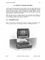
SELECTING A TERMINAL
Choosing a terminal depends on need and availability. Crt (cathode ray tube) terminals are
best for programming, text entry and editing, and can print at higher baud rates (speeds)
than hardcopy terminals. Crt terminals have screens similar to a television screen, and are
also referred to as vdt's (video display terminals), although there are some differences.
Hardcopy terminals have print elements but do not have screens, and are used for printing
output, either text or graphics, although they also can be used for programming and editing.
Some terminals combine both video and printing features. Graphics terminals often have
both a video screen and a hardcopy capability. Some hardcopy units are independent of
the crt, some are attached.
All CUCCA terminal keyboards have upper and lower case. CUCCA also provides terminals
with APL character sets, and terminals specifically for graphics. All the terminals described
in this Manual can be used with both the DECSYSTEM-20 and IBM 4341 computers.
SUMMARY OF TERMINALS
New terminals are continually being installed on the Morningside campus. The list provided
below presents a brief description of those currently available.
Further explanations,
information about availability, restrictions, or special equipment are provided in the specific
sections.
(
(
CUCCA
Terminal And Plotter User Manual
November, 1982
Introduction
3
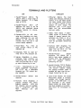
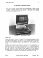
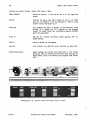
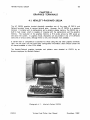
TERMINALS AND PLOTTERS
CRT
HARDCOPY
1. Hewlett-Packard
262 1A.
The
2621 A offers a large range of
special functions.
It is widely
used at CUCCA.
2. Hewlett-Packard
2621
AlP
(National), The same as the HP
2621 A with additional natural
language features for international use.
3. Concept-APL8. An APL character set is available, as is hardware windowing for use with
EMACS on the DEC-20. The
Concept APL8 also has a 132
column display capability.
4. Perkin-Elmer Fox
1100. An
older terminal without an APL
character set.
5. Datamedia 1520. An older terminal with an APL character set.
6. Intertec SuperBrain, A microcomputer used primarily for
transferring files from the IBM
4341 and the DEC-20 to floppy disks, Scheduling for use.
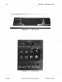
7. VT 10 1.
Manufactured by the
Digital Equipment Corporation,
the VT 10 1 has a detachable
keyboard and 132 column display capability,
8, Hewlett-Packard
opposite,
2623A.
See
9. Tektronix 4013 (Graphics!. A
graphics terminal with vector
graphics capability,
ASCII and
APL character sets are available,
Used in conjunction with the
4631
hardcopy
unit
(see
opposite),
CUCCA
1. DECwriter (Matrix). The most
widely used hardcopy terminal at
CUCCA, it is a dot matrix printer
(not letter quality) which allows
you to make a record of your
session or print output. The
DECwriter uses 1 1x 14 output
paper and can accommodate
narrower widths.
2, Diablo 1620 (Daisy). A letterquality printer to produce final
copies of essays, reports, dissertations etc. Prints in 10 or
12 pitch,
Wheels and ribbons
must be purchased, Scheduling
for use.
3, Tektronix 4631 (Graphics), The
hardcopy unit used in conjunction with the 40 13 crt. The
4631 prints the crt image,
4. Hewlett-Packard
2623A
(Graphicsl, The 2623A has a
built-in heat copier capable of
printing both the alphanumeric
and
the
graphics
memory.
Scheduling for use.
5, Hewlett-Packard 7221 S (Plotter).
Four-color graphics pen plotter
with vectors, rotation, scaling
and clipping facilities. Paper is
available but pens must be purchased. Scheduling for use.
6, Gould 5100 (Plotter), The Gould
electrostatic plotter is currently
available only through operator
service for the IBM 4341. It is
not described in this manual.
Please consult the Gould Technical Note available in the Reference Room for information on
usage.
Terminal And Plotter User Manual
November, 1982
Introduction
4
NOTES FOR NEW USERS
(
CUCCA offers several kinds of computer terminals to meet different needs. The preceding
paragraphs should familiarize you with the facilities. However, if you have never used a
computer terminal before, a few points might make your adjustment easier and thus
expedite your work,
USING A COMPUTER TERMINAL FOR THE FIRST TIME
If you have never used a computer terminal. it is best that someone show you the basics.
Consultants are available in the 5SI0 area and in Room 272A Engineering Terrace to answer
your questions and instruct you in the operation of the terminals. However, you may wish
to take instructions directly from the Manual.
A HELPFUL COMPARISON
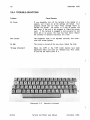
For many new users, the sight of the computer terminal keyboard immediately brings to
mind a typewriter.
This is particularly true of hardcopy terminals, which have print
elements instead of screens. The terminal keyboard closely resembles the keyboard of an
electric typewriter. The alphabetic and numeric arrangements are identical. although some
Backspace, caps lock, and shift keys
terminals have separate number pads as well,
perform the same function as on a typewriter. The carriage return key is located on the
right-hand side of the second bank of keys, as it is on an electric typewriter, and
performs roughly the same function, For further explanations of these keys as they relate
to typewriters and terminals, see the Concept 108 Users Manual pps. 1-4: 1-6, available in
the Reference Room in the SSIO area.
(
(
CUCCA
Terminal And Plotter User Manual
November, 1982
5
The First Step In Using The Computer
CHAPTER 1
THE FIRST STEP IN USING THE COMPUTER
1.1. PROCEDURES
The procedures for using the computer, listed in order of occurrence, are as follows:
1. Set up the terminal.
2. Turn on the PACX box and make a connection to the system.
3. Log in.
4. Do your work.
5. Log out.
This chapter presents comprehensive information about point 1.
1.2. SETTING UP THE TERMINAL IN THEORY AND PRACTICE
The first step in using most computer systems is to make sure that your terminal is set up
or "configured" for the system you will be using. This includes setting baud rate (terminal
speed!. parity, duplex and other parameters. (See the Glossary on p. 71 for definitions of
these terms.)
There are three distinct aspects to consider when configuring your terminal:
1. The IBM and DEC-20 systems require different values for certain settings,
e.g., parity. duplex etc.
2. Each terminal differs in the kinds of settings which are available and have to
be changed, although most terminals do share some common settings (see
below, section 1.4). For example, not all terminals have a handshake parameter,
but many have a duplex parameter. In short, different terminals have different
features; what you must change on one will not necessarily be present on
another. This will become clear after you have used at least two different
makes of terminals.
3. Each terminal differs in the physical manner in which these values are
established, i.e" older terminals tend to have switches and buttons, while the
newer terminals take typed-in sequences.
CUCCA
Terminal And Plotter User Manual
November, 1982
6
The First Step In Using The Computer
1.3. TWO BASIC RULES TO FOLLOW
(
1. Turning on the terminal is the first step in using one; it must be turned on
before it can be configured.
If you do not hear a beep or the screen
brighten after a minute to signify it is powered on, the terminal may be out
of order, although you should check to see that the brightness is turned up
and that the unit is plugged in. For hardcopy terminals you may physically
feel that the power is on if there are no indicator lights, but usually the print
element moves slightly to signal power on.
2. You should configure your terminal for the proper system before making a
connection with the computer through the PACX Gandalf blue box located
near the terminal. Some systems will not recognize changes in settings once
you have logged in, although others will. For PACX information see the 4341
Log In Procedures sheet or the DEC-20 Reference Card.
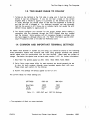
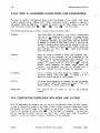
1.4. COMMON AND IMPORTANT TERMINAL SETTINGS
No matter what terminal or system you are using, you should be aware of the following
three parameters. Please note however that when using graphics terminals and plotters,
certain values must be synchronized with the host terminal. (Baud rates are subject to
change. See below the special note on baud rates, section 1.4.0.1 for further information.)
1. Baud Rate. The speeds appear as 300; 1200; 1800; 4800; 7200; 9600.
(
2. Parity. Parity value names differ for each terminal. but should generally be set
to none for both systems, although some terminals equate mark with none.
Please check each section for the choices.
3. Duplex. The settings will always appear as half or full.
The current values for these settings are:
SETTINGS
DEC-20
IBM 4341
Baud Rate
Parity
Duplex
4800
None'
Full
1800
None'
Half
Table 1-1:
IBM 4341 and
DEC-20 Settings
• The equivaient of Mark on some terminals.
(
CUCCA
Terminal And Plotter User Manual
November, 1982
The First Step In Using The Computer
7
1.4.0.1. SPECIAL NOTE ON BAUD RATES
The speeds indicated above are the maximum that PACX. not hardwired terminals, can
comfortably support. Development work is currently underway to allow a higher baud rate
for the IBM systems. But at present, 1BOO is the maximum baud rate for terminals
connected through the PACK Users also should note that individual crt's may have built-in
restrictions and therefore may not be capable of operating at the maximum speeds listed
above.
Hardcopy Baud Rates
Unless otherwise indicated, CUCCA's hardcopy terminals must be run at speeds of 300
baud or lower.
Graphics Terminals and Plotters
The HP pen-plotter can be run only at 1200 baud or lower. All other graphics terminals
may be run at the specified baud rate for that system. But the baud rate must be
synchronized with the host terminal. Consult the individual sections.
CUCCA
Terminal And Plotter User Manual
November, 1982
8
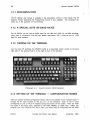
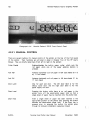
Concept-APl8
CHAPTER 2
CRT TERMINALS
(
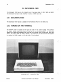
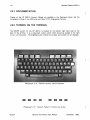
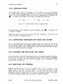
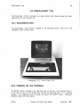
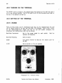
2.1. CONCEPT-APL8
The Concept-APl8 terminal is a microprocessor-based terminal which offers an APl
character set and advanced features such as hardware windowing. which are well
supported by EMACS on the DEC-20. The Concept-APl8 also has a 132 column display
capability.
2.1.1. DOCUMENTATION
Copies of the Concept Manual and Reference Card are available in the Reference Room in
SSIO.
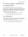
2.1.2. TURNING ON THE TERMINAL
The ON/OFF switch for the Concept is located In the rear center of the terminal. It should
be pressed to the left to turn on the terminal. The brightness knob is located on the left
side of the terminal under the screen housing. Turn it counterclockwise to brighten the
display.
(.
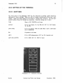
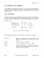
2.1.3. SETTING UP THE TERMINAL -- CONFIGURATION MODE
RESET/STAT Key
The Concept uses typed-in characters rather than switches to set its operation modes.
After turning on the terminal. press the RESET/STAT key on the Cursor Control Pad on the
upper right side of the keyboard (see photograph 2-3). This will display the inverse video
status line (white background with dark lettering), across the bottom of the screen. The
status may display many different values.
Following is a mode line configured for the
DEC-20:
KB 4800 FUll lSTOP NONE/OFF REM PROG CHAR
Figure 2-1:
U/l 047:003 ASC 000,000,048.080 F0100
Concept-APL Mode Line
(
CUCCA
Terminal And Plotter User Manual
November, 1982
9
Concept-APL8
Photographs: Peter Sprung
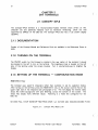
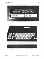
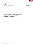
Photograph 2-1:
Photograph 2-2:
CUCCA
Concept-APi8
Concept-APL8 Keyboard
Terminal And Plotter User Manual
November, 1982
Concept-APL8
10
Note: Unlike some other terminals, the Concept APL does not display the names of the
settings, only the values, i.e" 4800 in the second field above refers to baud rate.
(
You need not be concerned with all the fields displayed on the mode line. The instructions
below correspond to the mode line, reading from left to right. Important settings are noted
in italics.
(
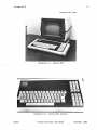
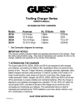
Photograph 2-3:
Concept APL-B Cursor Control Pad and Numeric Pad
(
CUCCA
Terminal And Plotter User Manual
November, 1982
11
Concept-APL8
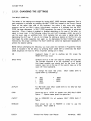
2.1.3.1. CHANGING THE SETTINGS
The MULT CODE Key
The values of the settings are changed by issuing MULT CODE character sequences, That is,
each sequence is prefaced by pressing the MULT CODE key located on the Cursor Control
Panel on the upper right side of the keyboard. You press it only once with regular
pressure, and do not hold it down, Unfortunateiy, nowhere is it indicated that the MULT
CODE has been depressed, In MULT CODE sequences, the case of the ietters is extremely
important Often a feature is enabled or disabled depending on the case of the letter, i,e"
upper or lower case, In the following. unless the word shift precedes a letter, be sure to
use the lower case or unshifted form, Shift indicates that you enter a capital letter by
depressing the shift key; If you do not change the setting as desired on the first try, you
must begin the entire sequence over again, I.e., by depressing the MULT CODE key again,
followed by the proper command, The MULT CODE key cannot be depressed repeatedly to
achieve the desired setting,
NOTE: Before attempting the following, you must place the terminal in Programmer Mode,
which is included in the list below, by pressing MULT CODE Shift U, Otherwise, the MULT
CODE .sequences will have no effect. Important settings are in italics,
(
,
KB
Keyboard mode, If set
RESET/STAT key twice,
to
anything
BAUD RATE
Symbols such as % and ( are used for setting the baud rate,
The Concept keyboard is an APL keyboard, so to quickly
find these symbols you should look on the front of the
numeric keys, not on the top of the numeric keys, as is the
case with most keyboards,
To change the baud rate press:
(capital letter 0), followed by:
%
*
300
1200
1800
2400
+
but
KB,
press
the
MULT CODE Shift 0
3600
4800
9600
DUPLEX
For IBM (half) enter MULT CODE Shift 8; for DEC-20 (full)
enter MULT CODE 8 ,
STOP
Should be set to 1STOP for speeds over 300; MULT CODE
Space < ", (Space means press the space bar,)
PAR/TY
Set to NONE/OFF for all systems; MULT CODE Shift P
Space,
REM/WC
Must always be set to REMOTE
computer, MULT CODE 9,
CUCCA
Terminal And Plotter User Manual
in
order
to use the
November. 1982
12
Concept-APL8
PROG
Programmer mode. MULT CODE Shift U. Can also be set
to User mode by MULT CODE u, but you cannot configure
the terminal in user mode.
CHAR
Should always be set to CHAR. If not, press MULT CODE 7.
U/L
Upper and lower case letters. MULT CODE % for upper
case; MULT CODE 5 for upper and lower case.
CURSOR POSITION
Indicates the position of the cursor on the screen.
ASC/APL
To enable for APL, MULT CODE 0 (numeral). To disable and
return to ASCII for regular use, MULT CODE SHIFT O.
(
The Numeric Keypad -- An Easy Way to Setup the Terminal
Note that some of the settings are clearly displayed on the Numeric Pad on the right side
of the keyboard (see photograph 2-3). For instance, "8" corresponds to Duplex, "9" to
Local/Remote, "5" to upper!lower case, and "0" to ASCIi/APL. Those markings on the top
half of the keys indicate that you use them in shifted mode, i.e., while depressing the shift.
You may use these numeric keys after typing a MULT CODE instead of the numeric keys
on the top row of the regular keyboard.
2.1,4. COMPLETING CONFIGURATION AND CLEARING THE STATUS LINE
(
You are now ready to use the computer. You can clear the status line by pressing the
RESET/STAT key. Recall the status line by pressing the RESET ISTAT key again.
2.1.5. RESETTING THE TERMINAL
Resetting the terminal puts it back to the state it was in when it was first turned on. Press
Shift RESET/STAT simultaneously.
2.1.6. OPTIONAL FEATURES
2.1.6.1.80/132 COLUMN DISPLAY
You may vary the display width between 80 columns, which is the default, and 132
columns, for typeout or editing. The change to 132 columns, enter the sequence MULT
CODE " (quotation marksl. To return to 80 columns, enter MULT CODE ! (exclamation point!.
(
CUCCA
Terminal And Plotter User Manual
November, 1982
Concept-APL8
13
2.1.6.2. REVERSE VIDEO
The Concept APL has a reverse video mode that is very easy to set. Most terminals offer
only white characters on a dark background. This is the default for the Concept, but you
can also invoke reverse video mode, Le., dark characters on a white background. Do this by
pressing MULT CODE Shift D. Adjust the brightness with the knob on the left under side
of the screen. Turn off the reverse video, that is, go back to normal video, by pressing
MULT CODE d. It is not a part of the standard configuration procedure; it does not appear
on the mode line nor does it affect the operation of the terminal.
2.1.7. TROUBLE-SHOOTING
Problem
Cause/Remedy
No Power
If you accidently turn off the terminal in the middle of a
session, the terminal will revert to the settings it had when
first turned on.
Your program should be intact, but you
may have to reconfigure the terminal. Press carriage return
or refresh the screen. No power or a loss of power will
also occur if the unit is not plugged in. Check the power
cord.
If the terminal is plugged in and powered on and
there still is no power, the fuse may have blown. Report
the condition to Systems Assurance, ext. 3100.
Dark Screen
If you cannot see the cursor on the screen, the brightness
knob is turned all the way down. Turn counterclockwise
until cursor appears or screen lightens. If this does not
work, see below "Strange" Modes.
Upper Case Only
Make sure U/C button on left is unlit; depress to turn off
light. Check the status line to indicate U/L and not CAP.
Computer Does
Not Respond
Check to see that Remote and not Local is enabled.
INSRT Mode Enabled
Insert Mode. The light will be lit. This may cause disruption
of text, especially while using EMACS on the DEC-20. To
disable, reset the terminal; see above.
"Strange" Modes
Unspecific symptoms include buzzing, strange patterns on
the screen, a missing cursor, bright vertical lines etc. Turn
off the terminal for about 10 seconds, and turn it back on.
You may need to reconfigure the terminal.
CUCCA
Terminal And Plotter User Manual
November, 1982
14
Datamedia 1520
2.2. DATAMEDIA 1520
(
The Datamedia 1520 has an APL character set. It has baud rates of 300. 1800 and 4800.
The Datamedia has been locally modified to allow a 4800 baud rate.
2.2.1. DOCUMENTATION
The Datamedia 1520 manual is available in the Reference Room in the 5510 area.
2.2.2. TURNING ON THE TERMINAL
The ON/OFF switch is located on the right rear side of the screen housing. The positions
are clearly marked; push the switch on the top to turn on the terminal. To focus the
screen first rotate the brightness knob, and then the contrast knob on the lower right hand
side of the casing (both are clearly marked). The volume of the belt can also be adjusted
by rotating the knob located on the right side of the keyboard.
(
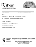
Photograph 2-4:
CUCCA
(
Datamedia 1520
Terminal And Plotter User Manual
November, 1982
15
Datamedia 1520
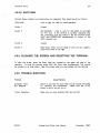
2.2.3. SETTING UP THE TERMINAL
2.2.3.1. SWITCHES
The front panel of the Datamedia 1520 has the following 8 switches which should be
depressed to record settings. When you want to change a setting push all the way in and
release. Labels have been placed on the buttons to indicate their functions. The sixth and
seventh buttons (those not markedl are inoperative. Important settings are in italics.
TAPE
Place in OUT POSITION at all times.
DUPLEX
IN for Full Duplex for the DEC-20; OUT for Half Duplex
for the IBM.
DATA RATE
IN for all systems. When the Data Rate is OUT a 300 baud
rate is established.
EIA
IN position at all times.
ASCII
IN for ASCII alphanumerics; OUT for APL character set.
LAST (8th) BUTTON
IN for 4800; OUT for 1800 for baud.
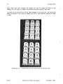
Photograph 2-5:
CUCCA
Datamedia Switches
Terminal And Plotter User Manual
November. 1982
Datamedia 1520
16
2.2.4. TROUBLE-SHOOTING
Problem
(
Cause/Remedy
No Power
If you accidently turn off the terminal in the middle of a
session, turn it back on; all the settings will remain. Your
program should also be intact. Press carriage return or
refresh the screen.
No power or a loss of power will
also occur if the unit is not plugged in. Check the power
cord.
if the terminal is plugged in and powered on and
there still is no power. the fuse may have blown. Report
the condition to Systems Assurance, ext. 3100.
Dark Screen
The brightness knob is not adjusted correctly; turn clockwise until screen lightens.
No Bell
The volume is turned all the way down. Adjust the knob.
"Strange Characters"
Either the TAPE or the TAPE LOAD buttons have been
depressed. Make sure both are released (out). Also. check
to see that the ASCII button is in.
(
Photograph 2-6:
Datamedia Keyboard
(
CUCCA
Terminal And Plotter User Manual
November. 1982
Hewlett-Packard 2621 A
17
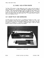
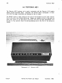
2.3. HEWLETT-PACKARD 2621A
The HP 2621 A offers an attractive character set and a large range of special functions
which give it the versatility necessary for use with much of the software currently available
at Columbia. For a summary of instructions about the HP 2621 A and HP2621 National
terminals. please see Appendix III, p. 76
(
Photograph 2-7:
Hewlett-Packard 2621 A
PLEASE NOTE
The HP 2621 A and the HP 2621 AlP National terminals are physically identical, but they
have slightly different settings.
Still. almost all of the information listed in this section
applies to the HP National as well. and thus is not repeated in that section. Currently. most
of the HP National terminals are located in the Carman terminal room. although this may
change.
The easiest way to determine which terminal you are using is to enter Configuration Mode
(see beiow section 2.3.3 p. 19) and examine the lower mode line. If LANGUAGE instead of
EX I T appears in the left most setting of the lower mode line it is a National terminal. The
mode lines are the white blocks with dark lettering which appear at the top and bottom of
the screen. Check p. 20 to see the mode line for the HP 2621A Also, check the Straps
parameter on the upper mode line. If it does not appear exactly as specified on p. 20,
i.e.. the National has an "a" in the field on the upper mode line, see below. 2.4. p. 25.
CUCCA
Terminal And Plotter User Manual
November, 1982
Hewlett-Packard 2621 A
18
2.3.1. DOCUMENTATION
(
Copies of the HP 2621 A Owner's Manual are available in the Reference Room and the
consultant's offices in the SSIO area and Room 272A Engineering Terrace.
2.3.2. TURNING ON THE TERMINAL
The ONIOFF switch for the HP 2621 A is located on the bottom right hand side on the
back of the terminal. It is a wide black rocker switch which should be pushed to the right
to turn on the power. The brightness and contrast are preset and should not be changed.
(
Photograph 2-8:
Hewlett-Packard 2621A Keyboard
DDlEIlDII
Photograph 2-9:
CUCCA
(
Hewlett-Packard Function Key Group
Terminal And Plotter User Manual
November, 1982
Hewlett-Packard 2621 A
19
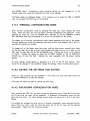
2.3.3. SETTING UP THE TERMINAL
2.3.3.1. FUNCTION KEY GROUP
The Function Key Group consists of eight Function Keys located across the top of the
keyboard (as illustrated opposite), and the Labels Key (the only blank key). located to the
right above the carriage return. These keys are used in a shifted mode, i.e., while holding
down the shift key, to configure the terminal for a given computer system. When the
keys are used without the shift key, they control cursor and scrolling functions. When
using these keys to configure your terminal. the computer has no knowledge that the
cursor has been moved. You cannot use these keys to position the cursor when using an
editor, e.g., EMACS.
After the terminal is turned on, eight labels--the Primary Labels--will appear along the
bottom of the screen. Each label corresponds to one of the eight function keys located
along the top of the keyboard.
There are six different sets of labels that may appear, depending upon what mode the
terminal is in. For the HP 2621A however, we will discuss only two sets, the Primary
Labels and the Configuration Mode Labels.
Note: When depressed, the Labels key calls back the primary labels, no matter what mode
you are in.
2,3.3.2, EXECUTING TERMINAL FUNCTIONS
Each of the labels along the bottom of the screen names a terminal function that you may
execute to achieve a desired effect.
There is a one-to-one correspondence between these labels and the function keys larrows)
on the top of the keyboard. The functions are executed by pressing the corresponding
function key while holding down the shift key.
When the terminal is turned on, the Primary Labels are initially displayed. In order to set
the values of various configuration parameters. you must put the terminal into
Configuration Mode.
NOTE: It is impossible to enter Configuration Mode unless the Primary Labels are currently
displayed. At any time you may recall the Primary Labels by pressing the Labels key, the
blank key on the right.
a
To enter Configuration Mode. hold down the shift key while pressing the
key.
Parameter labels and values will appear along the top of the screen. and the bottom labels
will change to the Configuration Mode labels.
The labels for the upper mode line are
displayed as follows for the DEC-20:
CUCCA
Terminal And Plotter User Manual
November, 1982
Hewlett-Packard 2621 A
20
Baud Rate
4800
Parity
NDNE(O)
Figure 2-2:
Duplex
FULL
Straps
bCGHxz
Handshake
etx
Hewlett-Packard 2621A
Hz
60
Start Col
1
Return
[or 1
(
Upper Mode Line Labels
Only those values below in italics should be changed. The recommended values for the
configuration parameters are:
SETTING
DEC-20
IBM 4341
Baud Rate
Parity
Duplex
Straps
Handshake
4800
NONE(OJ
1800
NONE(1)
Hz
Full
bCGHxz
etx
60
Start Col
Return
[cr ]
Half
bcGHxz
etx
60
1
[cr ]
Table 2-1:
,
Hewlett-Packard 2621A
Value Settings
(
The lower mode line will also be displayed:
EXIT
NEXT
PREVIOUS
Figure 2-3:
MODM OFF
REMOTE*
CAPS LK
LN MODE
AUTO LF
Hewlett-Packard 2621A Lower Mode Line Labels
Note: Only the REMOTE function is enabled 1*1. See below 2.3.3.4. p. 22.
2.3.3.3. STEP 1--CHANGING UPPER MODE LINE PARAMETERS
Change the values if they do not conform to the above chart. This is very easy to do.
and once you have changed one parameter. you wiil understand how to change the
remainder.
First select the parameter that needs to be changed. i.e., baud rate. parity etc. Do this by
positioning the cursor under the proper field using the I:lI and £:II
keys on the upper
right side of the keyboard, unshifted, that is, without pressing the shift key.
Each parameter is changed by pressing the shift and the
the _
key.
CUCCA
!I
Terminal And Plotter User Manual
key andlor the shift and
(
November. 1982
Hewlett-Packard 2621 A
21
IIi3 or E:II keys to
Once the parameter is changed to the proper value, press the
move to the next field and repeat the procedure. Those parameters in italics are different
for each system.
BAUD RATE
To
change the baud rate, press the shift and the
key. Once may not be enough however to get the
proper value. To change the value again, continue to press
the
elII key while holding down the shift until the
desired value appears. In other words, don't remove your
finger from the shift key, but continue to press the
elII
key.
The elII
key returns higher values. The
_
key returns lower values. You can use either one.
elII
PARITY
The parity is changed in the same manner as the baud rate.
After positioning the cursor to the proper location, press
the shift and elII
key until the proper setting appears.
For the IBM 4341 the setting is NONE( 11 and for the DEC20 NONE(O).
DUPLEX
Same as above. For the DEC-20 it is set to Full, for the
4341 to Half.
STRAPS
Straps operate slightly differently, since the cursor is positioned under each letter instead of the entire field. If one
of the letters is not in the correct case, you must change
it by moving the cursor underneath the letter that must be
and E:II
keys unshifted), and
changed (using the IIi3
then pressing the shift and elII key.
HANDSHAKE
Handshake works the same as Straps.
If the current
Handshake setting is eTx, and you must change this to etx,
do the following. First, position the cursor under the T in
eTx by using the IIi3
and/or E:II
keys. Then press
shif t elII. The upper case T will change to a lower case
t, leaVing the Handshake parameter with the value, etx.
Hz
Should not be changed if set to 60. If it is not set
properly, change in the same manner as indicated above.
START COL
Should not be changed if set to 1.
If it is not set
properly, change in the same manner as indicated above.
RETURN
This generally should not be changed
However, if it is
ever anything other than [cr 1 you may change it as
follows: First position the cursor so that it is immediately
to the right of the left bracket L using the IIi3
and/or
E:II keys. Then press the RETURN key followed by the
SPACE bar.
CUCCA
Terminal And Plotter User Manual
November, 1982
22
Hewlett-Packard 2621 A
2.3.3.4. STEP 2--CHANGING LOWER MODE LINE PARAMETERS
(
The last four labels in Configuration Mode control the settings of four modes. Each mode
is either enabled (on) or disabled (off). When a particular mode is enabled, an asterisk *
will appear inside the label box. To change the state of one of these modes, you use the
E:lI ,and 0 in shifted mode.
right-hand side function keys 0
,a ,
The modes should be set as follows. Those in italics should be noted.
REMOTE
This mode MUST be enabled if you wish to communicate
with any of the computers at Columbia. To enable Remote
press shift 0
and the * will appear. Often this mode
is accidently disabled, and users think that the terminal
is broken or the line is bad. Please check to see that this
function is enabled before reporting the terminal or line out
of order. To disable the Remote mode, simply repeat the
same function, i.e., press the 0
again while holding
down the shift key.
CAPS LK
When this mode is enabled all lower-case aiphabetic characters typed .at the keyboard will be transmitted to the
computer as the corresponding upper-case characters. An
* will appear in the corresponding label to signify it is
enabled. To disable CAPS LK, press shift
and the
asterisk should disappear. To enable, simply repeat the
function.
Non-alphabetic keys are not effected, and no
characters received from the computer are translated.
a
LN MODE
If it is
This is a special mode that should be disabled.
accidently enabled, press shift E:lI
to disable it. If enabled. you cannot connect to the computer.
AUTO LF
This mode should generally be disabled, but may be enabled
as a convenient method for typing out a piece of text with
double spacing. To enable, press shift 0
MODM OFF
This function
systems.
has
no
effect
on
any
of
the
(
Columbia
2,3.4. COMPLETING CONFIGURATION MODE AND EXITING
Once the parameters are properly set, you may exit Configuration Mode. The EXIT function
is used to restore the screen to the state it was in before entering Configuration Mode
and display the Primary Labels at the bottom of the screen. To exit, simply repeat the
function for entering, i.e., press shift ~
The top labels will disappear. You may also
exit by pressing the Labeis key. Use the Labeis key if some other mode is accidently
selected. You are now ready to make a connection with the computer.
(
CUCCA
Terminal And Plotter User Manual
November, 1982
23
Hewlett-Packard 2621 A
2.3.5. CLEARING AND RECALLING THE LABELS
If you do not wish to see the Primary Labels while you are using the computer, hold down
both the shift and Control (ctrl) keys while pressing the Labels key; the labels will
disappear.
To bring back the labels, (and you must have them displayed to enter
Configuration Mode), simply depress the Labels key.
2,3,6. THE COLUMN COUNTER
Another reason for recalling (or leaving) the Primary Labels, other than as an intermediate
step for getting Into Configuration Mode, is that the column counter appears in the middle
of the line of Labels. This counter always displays the screen column in which the cursor
is currently located. It is often useful when entering data into tables or according to some
strict format.
2.3.7. ENTERING CONFIGURATION MODE WHILE CONNECTED TO
THE COMPUTER
If you wish to change a setting during a session, enter Configuration Mode as previously
described. As long as the Primary Labels are displayed, simply press the shift and
key to display the settings.
m
2.3.7.1. RESETTING THE TERMINAL
Resetting the terminal puts it back to the settings when it was first turned on. If the
battery is dead, it will revert to factory settings. To reset, press the Break key while
holding down both the shift and Control keys.
You may at this point have to enter Configuration Mode and change some of the mode and
parameter settings. If this does not correct the problem, please report the terminal to
Systems Assurance, 280-3100.
CUCCA
Terminal And Plotter User Manual
November, 1982
24
Hewlett-Packard 2621A
2.3.8. TROUBLE-SHOOTING
Problem
(
Cause/Remedy
No Power
If you accidently turn off the terminal in the middle of a
session. turn it back on; all the settings will remain. Your
program should also be intact. Press carriage return or
refresh the screen.
No power or a loss of power will
also occur if the unit is not plugged in. Check the power
cord.
If the terminal is plugged in and powered on and
there still is no power, the fuse may have blown. Report
the condition to Systems Assurance, ext. 3100.
No Labels/Wrong Labels
Press the Labe/ s key to display the Primary Labels.
Upper Case Only
Press the CAPS key on the left of the keyboard. Check the
lower Configuration Mode labels to make sure that CAPS
LK is disabled (no *).
Alphabetic Keys
Transmit Digits
The numeric keypad feature has been accidently enabled.
Press the NUM key once to disable.
Compl1ter Does
Not Respond
Check to see that Remote is enabled (with a *).
LN MODE is disabled (no *).
Test Mode
If you wanted to enter Configuration Mode and accidently
key instead of the
key you will
pressed the
be placed in test mode. which displays an alphabetic pattern.
This mode only lasts for a few seconds; after it is finished,
enter Configuration Mode as indicated previously.
m
Make sure
m
(
2,3.8.1. SPECIAL PROBLEMS
If when the terminal is turned on the Configuration Mode labels instead of the Primary
Labels are initially displayed, simply continue as if you had intentionally placed the terminal
in Configuration Mode, and inform Systems Assurance of the number of the terminal.
(
CUCCA
Terminal And Plotter User Manual
November, 1982
25
Hewlett-Packard National
2.4. HEWLETT-PACKARD NATIONAL
The HP 2621 AlP National terminal is almost identical to the HP 2621 A except for an
additional strap in the Configuration Mode labels. and an additional Language Mode. Language
in this case does not refer to computer languages but to natural language.
The two
terminals are physically identical, and you may not be able to discern which one you are
using until you enter Configuration Mode. since the Primary Labels (the labels you see when
first the terminal is turned on) are also identical.
NOTE: The straps and the U5 language setting are the only settings that are different on
the HP Nationals. Therefore, only these will be explained below. For all other instructions
for the HP National terminal, please see above, section 2.3.
2.4.1. DOCUMENTATION
Copies of the HP 2621 AlP National Owner's Manual are available in the Reference Room
and the consultant's offices in the 5510 area and Room 272A Engineering Terrace.
Photograph 2-10:
CUCCA
Hewlett-Packard NatIonal
Terminal And Plotter User Manual
November, 1982
26
Hewlett-Packard National
2.4.2. SETTING UP THE TERMINAL -- CONFIGURATION MODE
(
2.4.2.1. CHANGING THE STRAPS
You enter Configuration Mode in the same manner as you do for the HP 2621 A.
Once the upper mode line Is displayed, you will see that all the straps are the same as the
HP 2621 A except for an additional Escape Sequence Transmission parameter, "a" in the
strap field. This must be disabled, i.e., lower cased. Place the cursor under the "a" and
execute the proper function. See above p. 21 for instructions on how to adjust the strap.
The upper Configuration Mode line appears as follows:
Baud Rate
1800
Parity
NONE ( 1 )
Figure 2-4:
Duplex
HALF
Straps
aboGHxz
Handshake
etx
Hz
60
Start Col
1
Return
(or)
Hewlett-Packard National Upper Mode Line Labels
2.4.2.2. LOWER MODE LINE
The lower mode line of the Configuration Mode is the same as on the HP 2621A with the
exception of LANGUAGE appearing on the lower left. Still, Remote must be enabled, and
this is accomplished in the same manner as stated above on p. 22.
LANGUAGE
NEXT
PREVIOUS MODM
Figure 2-5:
DFF
REMOTE<
CAPS LK
LN MODE
.
(
AUTO LF
Hewlett-Packard National Lower Mode Line Labels
(
CUCCA
Terminal And Plotter User Manual
November, 1982
27
Hewlett-Packard National
2.4.3. LANGUAGE MODE
The Language Mode. which is not available on the HP 2621 A must also be configured.
You cannot enter the Language Mode directly; you must first be in Configuration Mode.
When in the initial Configuration Mode. you enter the Language Mode by pressing shift
GIl
The labels on the bottom of the screen will change to the following:
D
DK/N
Figure 2-6:
E
F
SISU
UK
US*
Hewlett-Packard National Language Mode
US (United States) must be enabled for proper transmission. ShIft
"*" means it is enabled.
0
Please note however, that you are in a mode other than Configuration.
mode to get back to Configuration Mode.
to enable US. An
You must exit this
2.4.4. COMPLETING CONFIGURATION MODE AND EXITING
This is a two-step process. First you exit Language mode, and only then can you exit the
first Configuration Mode. Exit Language Mode by pressing the Labels key; you will be
returned to Configuration Mode. Exit Configuration Mode by pressing the Labels key again.
You are now ready to login to the computer.
2.4,5. CLEARING AND RECALLING THE LABELS
If you do not wish to see the Primary Labels while you are using the computer, hold down
both the shift and Control keys while pressing the Labels key; the labels will disappear.
To bring back the labels, (you must have them displayed to enter Configuration Model.
simply depress the Labels key.
2.4.6. RESETTING THE TERMINAL
Resetting the terminal puts it back to the settings when it was first turned on. If the
battery is dead, it will revert to factory settings. To reset, press the Break key while
holding down both the shift and Control keys.
You may at this point have to enter
Configuration Mode and change some of the mode and parameter settings. If this does
not correct the problem, please report the terminal to Systems Assurance.
CUCCA
Terminal And Plotter User Manual
November, 1982
28
Intertec SuperBrain
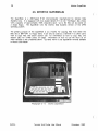
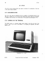
2.5. INTERTEC SUPERBRAIN
(
The SuperBrain is a Z80-based 8-bit microcomputer manufactured by Intertec Data
Systems Corp. It is equipped with two double-density 5-1/4 inch "minifloppy" disk drives
with a capacity of approximately 160K characters each. Up to 64 files can be stored on
a single floppy.
The SuperBrain runs the Intertec Data Systems version of the CP 1M
operating system.
The primary purpose of the SuperBrain is as a facility for copying files from either the
DEC-20 or IBM 4341 to floppy disks. It can only be used as a terminal if no other users
wish to copy files. See below section 2.5.1 for information on how to copy files. and
section 2.5.2 for further policy on usage. Information on how to use the micro as an
ASCII terminal is also presented below. Currently there is one SuperBrain terminal available
in Room 272A Mudd.
(
Photograph 2- 11:
f ntertec SuperBrain
(
CUCCA
Terminal And Plotter User Manual
November. 1982
Intertee SuperBrain
29
2.5.1. DOCUMENTATION FOR FILE TRANSFER
KERMIT is the program used for copying files to and from the DEC-20 or IBM computers.
The Kermit Technical Note for the IBM 4341 is available free of charge. For the DEC-20,
the Kermit Manual is available for purchase, but an excerpt of the Manual is also available
free of charge in the Reference Room in the SSIO area, room 115A.
2.5.2. USAGE POLICY AND SCHEDULING
The primary purpose of the SuperBrain is for file transfer to and from floppy disk.
Anyone using them for other purposes. i.e., as a terminal, must yield to users who need to
transfer files. Signup sheets are provided for scheduling of 20-minute slots. The length. of
the slot may be adjusted depending on requirements and demand. During periods of heavy
usage, t(he end of the semester), CUCCA reserves the right to limit use of the micro for
floppy access only.
2.5.3. OPERATING THE SUPERBRAIN
2.5.3.1. TURNING ON THE TERMINAL
1
To turn on the SuperBrain, flip up the toggle switch located on the back right-hand side.
This is known as a cold start. On a cold start the micro is automatically "booted", i.e. the
operating system is loaded into memory from the System floppy and started. After the
appropriate disks are loaded, (see below section 2.5.5), the following message will appear:
64K SUPERBRAIN DOS VER 3.1 FOR CP/M 2.2
A>
The "A>" is the micro's prompt. which signifies it is ready to accept input.
2.5.3.2. INTERRUPTING THE PROGRAM
There are two red keys located at the bottom corners of the main keypad. If these two
keys are depressed at the same time a warm start takes place; this means that whatever
program may be running is interrupted. the operating system is reinitialized, and you are put
back at CP/M command level. This is preferable to shutting off the terminal.
1
.
These sectIons
are excerpte d from the Kermit Users Guide
Cruz, and Daphne Tzear.
CUCCA
d
~
SpecifIcation by Bill Catchings. Frank d a
Terminal And Plotter User Manual
November, 1982
Intertec SuperBrain
30
2.5.4. USING THE SUPERBRAIN AS AN ASCII TERMINAL
(
The SuperBrain emulates a VT52 terminal. Start up the micro with the system disk mounted
in the A drive. The B drive should be empty.
2.5.5. USING FLOPPY DISKS WITH THE SUPERBRAIN
The SuperBrain uses a pair of 5-1/4 inch single-sided, double density, soft-sectored
floppies, A (left) and B (right).
The System floppy disk should be mounted in Drive A, and should not normally be
removed. The System Floppy is available from the consultant when you leave your ID card.
The system disk contains the CP/M operating system and utilities, and the SuperBrain
version of Kermit, Kermit-80.
Drive B is available for user floppies. It is the vertical opening on the right. To insert a
disk in Drive B, open the drive by applying a very slight outward pressure on the small flat
door located in the center of the opening. Insert the disk with the label facing right, away
from the screen, notched edge up. Make sure the disk is all the way in by applying a
gentle' pressure on the rear edge of the disk. Once you are certain that the disk is fully
inserted, you may close the disk drive door by applying a slight pressure on the door,
pulling it back in the direction from which it was originally opened. Once the micro has
been started, you may give it commands.
(
When you are finished using the SuperBrain, remove the disks and turn it off. Turning of
the terminal with the disks still in place can cause damage.
2.5.5.1. DEC-20
Then run Kermit and login on the DEC-20 as follows. You type what is in italics. All text
starting with a "!" to the end of the line is a comment, and everything else represents
computer typeout.
A>B:
B>A:KERM/T
! Switch to your disk.
! Run Kermit.
Kermit V 1.1
Kermit-80>
! Kermit prompt on the micro
Kermit-80>CONNECT
! Connect to the DEC-20.
! Set PACX to 12, etc.
(
CUCCA
Terminal And Plotter User Manual
November, 1982
31
Intertec SuperBrain
2.5.5.2. IBM
Set up the systems disk as indicated above. then do the following:
B>A:Kermit
Kermit-BO>Set loc on
Kermit-80>Set ibm on
Kermit-80>Set baud
Kermit-80>
Kermit-80>CONN ECT
! Indicate half duplex
! Cause line turn around wait
! Will list 15 baud rates - choose
1800
Kermit prompt on the micro
Connect to the IBM.
Set PACX to 13.
The micro will act as a regular terminal from now on.
Login as you would normally.
Logging Out
For both the DEC-20 and and IBM systems. logout as indicated for both systems. Then
type Control-] C. Control means the control key. You are returned to the micro.
For documentation on Kermit. see above p. 29.
2.5.6. NOTES ON FLOPPY DISKS
Floppy disks (flexible disks. diskettes!. provide economical "removable media", i.e.. a cheap
way to store files offline such that they can be restored at a later time. Floppies consist
of a flexible platter mounted permanently inside a square cardboard jacket. The platter
turns inside the jacket. The machine's read-write head actually comes in contact with the
surface of the platter through a slot in the jacket. The rubbing of the platter against the
inside of the jacket and the read-write head can cause the the floppy to wear out after
prolonged or repeated use.
,
The jacket, in turn. is often kept in a paper envelope. The floppy is taken out of the
paper envelope and inserted in the drive with its jacket on. Floppies should never be
removed from their cardboard jackets. The shiny surface of the disk should never be
touched; always handle disks by their jackets. Disks shouid be stored in a box or solid
container. Never have the disks in their drives while the power is being turned on or off.
Do not bend the disk, or allow liquids or moisture to come in contact with the disk. Do
not place disk where they might be subject to magnetic fields, temperature extremes. dust,
or other contaminants. Finally. to not write on the jacket with a ball point pen.
CUCCA
Terminal And Plotter User Manual
November. 1982
32
Intertee SuperBrain
2.5.6.1. STORAGE CAPACITY
(
One floppy can hold about 160,000 characters (equivalent to about 60 DEC-20 file pages),
in up to 64 files.
2.5.6.2. PURCHASE OF FLOPPY DISKS
Users may purchase floppy disks in the User Services Office, 115 Computer Center.
CUCCA cannot guarantee that disks purchased elsewhere will be compatible with the
SuperBrain.
(
(
CUCCA
Terminal And Plotter User Manual
November, 1982
33
Perkin-Elmer 1100
2.6. PERKIN-ELMER 1100
The Perkin-Elmer 1100 crt terminal is an older terminal which features upper and lower
case. but has no APL character set.
2.6.1. DOCUMENTATION
The Perkin-Elmer 1100 manual is available in the Reference Room.
consultant's office in Room 272A
Photograph 2-12:
1158, and in the
Perkin-Elmer 1100
2,6.2. TURNING ON THE TERMINAL
The ONiOFF switch is located on the right hand side on the back of the terminal. Press it
to the right to turn on the terminal. The terminal will beep and blink if it is working
properly.
The brightness knob is located just above the ON/OFF switch.
Clockwise
movement makes the screen darker.
CUCCA
Terminal And Plotter User Manual
November, 1982
Perkin-Elmer 1 100
34
2.6.3. SETTING UP THE TERMINAL
(
Terminal settings can be made with the terminal on or off, and while you are signed on to
the computer. Terminal switches are located in a well beneath the logo plate in the upper
right-hand corner of the keyboard and a series of configuration keys is on the left-hand
side of the terminal.
2.6.3.1. SWITCHES
Pry up the logo plate to reveal the switches (do not forget to replace it). The back of the
logo plate has all the markings necessary for configuring the terminal. Turn it over after
removing it, and place it horizontally to correspond to the switches and use it as a guide.
From left to right:
970211
6 204 8 263 2 1
o 0 8 0 0 0 000 1 7
o 0 4 0 0 0 0 0 005
I
I
I
I
I
I
I
I
I
I
I
I
I
I
I
,
I
I
BAUO RATE
I
I
ONE
I
I
TWO
FULL
I
I
HALF
s
P
A
c
I
I
E
STOP
BIT
OUPLEX
M
A
R
K
E
V
E
N
a
a
a
PARITY
(
Figure 2-7:
Perkin-Elmer 1/00 Settings
Usually, all that should be changed on the Perkin-Elmer are the baud rate and duplex.
BAUD RATE
Move switch horizontally, gUided by the settings on the
back of the logo plate, until it corresponds to the proper
settings.
STOP BIT
Leave at ONE (upperl for all systems.
DUPLEX
HALF (down) for IBM 4341; FULL (up) for DEC-20.
PARITY
MARK for the IBM; SPACE for the DEC-20. If you have to
change the setting while the terminal is on, press the Clear
All button to record the change.
(
CUCCA
Terminal And Plotter User Manual
November, 1982
35
Perkin-Elmer 1100
Photograph 2-13:
Photograph 2-14:
CUCCA
Perkin-Elmer Switches and Logo Plate
Perkin-Elmer Keyboard and Configuration Buttons
Terminal And Plotter User Manual
November, 1982
36
Perkin-Elmer 1100
2.6.3.2. CONFIGURATION BUTTONS
(
There are a series of configuration buttons on the lefthand side of the terminal (see
photograph 2- 14). Important settings are noted in italics. They should be set by depressing
them.
LINE
Must be depressed to connect to the computer. The same
as the REMOTE function on the HP and Concept terminals.
NEW LINE ENABLE
For the DEC-20. should be in an UP (disabled) position.
Should be DOWN (enabledl for the IBM.
BREAK
For use with all systems as indicated. Not a configuration
key.
SCROLL ENABLE
Should be depressed for all systems.
U/C
When depressed. will produce only upper-case output.
AUTO LF
Inserts an extra line feed for double spacing.
CLEAR ALL
Clears the screen of all text and leaves the cursor in the
upper-Iefthand corner and records settings made with the
terminal on. Also does a reset on the terminal.
HERE IS
Inoperative on CUCCA systems.
PRINT
Inoperative on CUCCA systems.
(
2.6.4. COMPLETING CONFIGURATION
Once you have correctly set all the values. replace the logo plate. Press the CLEAR ALL
button to initialize the settings. You are now ready to make a connection to the computer
through the Gandalf blue box.
(
CUCCA
Terminal And Plotter User Manual
November. 1982
37
Perkin-Elmer 1100
2.6.5. TROUBLE-SHOOTING
Problem
CauselRemedy
No Power
If you accidently turn off the terminal in the middle of a
session, turn it back on; all the settings will remain. Your
program should also be intact. Press carriage return or
refresh the screen.
No power or a loss of power will
also occur if the unit is not plugged in. Check the power
cord.
If the terminal is plugged in and powered on and
there still is no power, the fuse may have blown. Report
the condition to Systems Assurance, ext. 3100.
Dark Screen
If you cannot see the cursor on screen, the brightness
knob may be turned all th'e way down. Turn it counterclockwise until cursor appears or screen lightens.
Overwriting lines
Depress the SCROLL ENABLE key.
Cursor does not move
Depress the LI N E key.
Upper Case Only
Make sure UIC button on left is in the up position.
Double Spacing
AUTO LF (automatic line feed) button is in the up position.
Everything is correct
Press Clear AI! to initialize the settings.
CUCCA
Terminal And Plotter User Manual
November. 1982
VT101
38
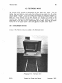
2.7. VT101
(
The VT 10 1, like the Concept-APL8, uses typed-in characters for configuration. It also has
a 132 column display capability.
2.7.1. DOCUMENTATION
The VT 10 1 User Guide and Reference Card are available in the Reference Room in the
S510 area. In addition, the VT 10 1 Set-Up Card, listing all the proper values for the settings,
is available at each terminal on the reverse side of the keyboard (see photograph 2-16).
2.7.2. TURNING ON THE TERMINAL
The ON/OFF switch is a cylindrical toggle switch located on the left rear side of the
terminal.
Push it up to turn on the terminal.
For adjusting the brightness, see below
section 2.7.3.1.
(
Photograph 2-15:
CUCCA
VTf01
Terminal And Plotter User Manual
(
November, 1982
VT10,
39
2.7.3. SETTING UP THE TERMINAL -- SET UP MODES A AND B
There are two set up modes on the VT101; A and B. You must enter Mode A before
Mode B. Enter Set Up Mode A by pressing the Set-Up key in the upper left- hand corner;
it is clearly marked. Enter Set-Up Mode B from Mode A by pressing the number 5 key.
2.7.3.1. SET-UP MODE A
You change the following settings in this mode:
Tabs
The SET/CLEAR tab and CLEAR ALL tabs use the number 2
and 3 keys respectively, as indicated on the main keyboard.
To set tabs manually, use the < and > keys on the upper
right side of the terminal to set the tabs in the position you
want them then press SET/CLEAR. When tabs are set, a
"1" will appear above the mode line. Software is available
on the DEC-20 to automatically set up the tabs. IBM users
may set tabs in Wylbur.
Brightness
Adjust the brightness by pressing the up-arrow and downarrow keys located on the right side of the upper row of
the main keyboard. Press as many times as necessary to
achieve the desired brightness.
Local/Online
MUST be set to ONLINE for all systems. Press the number
4 key on the main keyboard to switch between the two
modes. The corresponding lights above the keyboard will
show which mode you are in.
80/132
Choose between using a normal 80 column width or 132,
for wider files. To do this, press the number 9 key. You
should immediately see the change in character width on
your screen. To get back to 80 columns, press 9 again.
2.7.3.2. EXITING SET-UP MODE A
When first configuring your terminal, you must enter Set-Up Mode B before exiting SetUp Mode A. If you have already configured your terminal however, and simply want to
enter and exit from Set-Up Mode A, press the Set-Up key, as indicated on the terminal
screen.
2.7,3,3. SET-UP MODE B
To enter Set-Up B mode from Mode A, press the number 5 key on the main keyboard.
Seven settings will appear along the bottom of the screen. The four left most settings vary
CUCCA
Terminal And Plotter User Manual
November, 1982
40
VT101
between 0 for off and 1 for on. Using the < and > keys, position the cursor directly
over the setting, then use the Toggle 1/0 key (the number 6 key) to vary between 0 and 1.
Only the fourth block, third position, Duplex need be changed for the different systems. All
others should be left at the following settings:
0101
0010
Figure 2-8:
0000
(
0010 (for lBM)
0000 (for DEC-20)
VTlOl Set-Up Mode B--Four Left Fields
The three right fields are displayed as follows:
p= 7M
p= 8N
FIgure 2-9:
Parity (P=)
Baud Rate(T=/R=)
T= 1800 R= 1800 (for IBM)
T= 4800 R= 4800 (for DEC-20)
VTlOl Set-Up Mode B--Three RIght Fields
Set to 8N (8 No parity for the DEC-20) by pressing the
shift key and then depressing the P key until the proper
value appears. Set to 7M (7 Mark) for the IBM in the same
manner.
(
Press the number 7 key to alter the transmit speed and
the number 8 to modify the receive speed. These must be
synchronized. Keep depressing these keys until the desired
values appear.
2.7.3.4. EXITING SET-UP MODE B
As instructed on the screen, you exit this mode by pressing the Set-Up key again. If you
wish to return to Set-Up Mode A, press the number 5 key on the main keyboard. You
may reenter Set-Up mode A at anytime by pressing the SETUP key.
2.7.4. RESETTING THE TERMINAL
If you want to reset the terminal to its settings when it was first turned on, while in either
A or B configuration mode press the RESET key (numeral 0) in the keyboard.
(
CUCCA
Terminal And Plotter User Manual
November, 1982
VT10l
41
{O~US
U.S.lUK
Auto Repeat
{Q:Off
'0""
Auto Wrap {~.=g::
Line Feed!
Q'Da'k Backgrfld
S Creen { l'Ught Backg.-nd
Cursor
New Line
{a.OIl
I-On
r-r-r.'r...,' 5'"
1 0 I 0 I
Margin Bell
Key Click
AnSIIVT52
Auto XOn XOff
3
{ o·on
'0""
{ ooon
l~On
{~:::;2
{?:8:
4
00
P=
06C-
Set-Up
E=Even Parity
O=Odd Parity
N=No Parity
S=Space Parity
M=Mark Parity
Interlace {~:.g::
Q=UnOert:ne
{ I'Block
momoomo
7=7 Data Bits
8=8 Data Bits
I~UK
Character Set
'b Ii -p£.e?o T=
7 \ll-t;I>",
use A Pen<:~ To
RecOl'd Too
Set-Up Features
You Have Se!e<led
ffim
R=
c.EEE8
Receive Parity {O-Ignore
1-Check
WPS Terminal
Local Echo
{?:f:
{?.g:
t
t
Power {O-5O
Hz
\-SO Hz
-
-
To lrn:rease SCleen Brtghtness
To Decrease Screen Brightness
80 CoUrros Per Une
1n C()lurros Per Line
Answer Back:
Tabs:
Photograph 2-16:
lb1649901
VTlOI Set-Up Card
2.7.5. OPTIONAL FEATURES
2.7.5.1. 80/132 COLUMN DISPLAY
You may change the display width from the 80 columns, which is the default, to 132
columns, for typeout or editing. See above p. 39 for instructions.
2.7.5.2. REVERSE VIDEO
The VTl 0 1 has a reverse Video mode that is very easy to set. Most terminals offer only
white characters on a dark background. This is the default for the VTl 01, but you can also
invoke r'everse video mode, i.e., dark characters on a white background. Do this in SET-UP
Mode B, setting the fourth field in the first block of boxes to 1, i.e.. 01 11. Turn off the
reverse video by setting it back to O.
It is not a part of the standard configuration
procedure; it does not appear on the mode line nor does it affect the operation of the
terminal.
CUCCA
Terminal And Piotter User Manual
November, 1982
42
VTlOl
2.7.6. TROUBLE-SHOOTING
Problem
(
Cause/Remedy
No Power
If you accidently turn off the terminal in the middle of a
session, turn it back on; all the settings will remain. Your
program should also be intact. Press carriage return or
refresh the screen. No power or a loss of power may
also occur if the unit is not plugged in. Check the power
cord.
If the terminal is plugged in and powered on and
there still is no power, the fuse may have blown. Report
the condition to Systems Assurance, ext. 3 100.
No Repeating Action
In Set-Up Mode B, check the first field,
Should be set to 1 for ON.
Keyboard Lock
If XOFF is not set. that is, if XON is accidently enabled,
you will lock the keyboard and will not transmit characters.
You will have some trouble connecting to the IBM. The
Keyboard Lock light will go on. If this happens, you must
set XOF F. The XON/XOFF (handshaking) parameter is in the
second block of boxes in Set-UP Mode B, in the fourth or
last field. See the diagram above in section 2.7.3.3. It should
be set as follows: 0010 -- the last 0 meaning XOFF is
enabled.
second box.
(
(
CUCCA
Terminal And Plotter User Manual
November. 1982
43
DECwriter LA36 Matrix Printer
CHAPTER 3
HARDCOPY TERMINALS
3.1. DECWRITER LA36 MATRIX PRINTER
The DECwriter is the most widely-used hardcopy terminal available at CUCCA. The printing
element forms tiny dots which together produce the likeness of the keyboard character
set. CUCCA provides the standard continuous-form, pin-feed type paper in size 11 x 14
inches for these terminals. The DECwriter LA36 matrix printer offers upper-lower case,
110, 150 and 300 Baud rates, and an APL character set.
3,1.1 , DOCUMENTATION
A copy of the LA36 DECwriter manual is available in the Reference Room in the 5510 area.
Photograph 3-1:
CUCCA
LA36
Terminal And Plotter User Manual
November, 1982
44
DECwriter LA36 Matrix Printer
(
Photograph 3-2:
LA36 Keyboard
(
Photograph 3-3:
LA36 Switches
(
CUCCA
Terminal And Plotter User Manual
November, 1982
45
DECwriter LA36 Matrix Printer
3.1.2. PAPER
The paper for the DECwriter is fed into the roller from a box located under the terminal
on the floor. Please make sure the paper is held firmly by the tractor. After your session
is finished. tear off the paper by rotating the roller on the ieft-hand side until the
perforation is visible. If there is no paper in the terminal or the ribbon is very faded or
otherwise mangled. please inform Systems Assurance.
3.1.3. TURNING ON THE TERMINAL
The DECwriter is an extremely easy terminal to operate. All the switches are located on the
left side of the keyboard and are clearly marked.
The ON/OFF switch is clearly marked and should be pushed to the right to turn on the
terminal.
All the other switches are the push-to-set type. The dot on the switch indicates the
function of the switch when depressed. Please note those settings in italics.
3.1.4. SETTING UP THE TERMINAL
LlNE:LOC
UP for computer usage; DOWN for local usage.
ALT CHAR SET
UP for ASCII; DOWN for APL.
CHAR SET LOCK
To lock terminal in current character set. DOWN to lock,
UP to unlock.
FDX/HDX
UP is FULL DUPLEX
DUPLEX for the IBM.
HERE IS
INOPERATIVE,
110
IN for 110 Baud Rate, Baud Rate switch 300 should be in
the up position.
300
IN for 300 Baud Rate, Baud Rate switch 150 should be in
the up position.
To establish a 150 baud rate both the
110 and 300 switches should be down,
AUTO LF
DOWN for double spacing; UP for single spacing.
CUCCA
for the DEC-20; DOWN is HALF
Terminal And Plotter User Manual
November. 1982
46
DECwriter LA36 Matrix Printer
Special Note on the PACX Gandalf Blue Box
(
PACX boxes are usually attached to the DECwriter terminals on the right hand side of the
base.
3.1.5. TROUBLE-SHOOTING
Problem
Cause/Remedy
No Power
If you accidently turn off the terminal in the middle of a
session, turn it back on; all the settings will remain. Your
program should also be intact. Press carriage return or
refresh the screen. No power or a loss of power may
also occur if the unit is not plugged in. Check the power
cord.
If the terminal is plugged in and powered on and
there still is no power, the fuse may have blown. Report
the condition to Systems Assurance, ext. 3 100.
Bad Ribbon
If the ribbon is too light or otherwise mangled, please
report it to Systems Assurance, 280-3100.
No Paper
Please report to Systems Assurance, 280-3100.
(
(
CUCCA
Terminal And Plotter User Manual
November, 1982
47
Diablo 1620 Hyterm Printer
3.2. DIABLO 1620 HYTERM PRINTER
The Diablo 1620 terminal is a letter-quality printer which is used to print final copies of
essays, dissertations, etc. The quality of Diablo output is comparable to that of an electric
typewriter. Unlike most hardcopy terminals at CUCCA, the Diablo has been modified to run
at 1200 as well as 300 baud. The higher speed will expedite your work. To use this
terminal you must purchase a print wheel and ribbon available in the User Services Office,
Room 115, Computer Center (see below section 3.2.2). The Diablo terminal is located in
Room 272A Engineering Terrace.
3.2,1. USAGE POLICY AND SCHEDULING
The Diablo should not be used in lieu of a crt terminal but expressly
book is maintained in Room 272A for scheduling purposes. Access
first served basis, but users are encouraged to reserve a time slot in
are limited to a maximum of 1 1/2 hours of consecutive usage if
Demand is usually very heavy at the end of the semester.
Photograph 3-4:
CUCCA
as a printer. A log
is on a first come,
advance. Time slots
others are waiting.
Diablo 1620
Terminal And Plotter User Manual
November, 1982
48
Diablo 1620 Hyterm Printer
3.2.2. DIABLO SUPPLIES
(
A print wheel and ribbon cartridge can be purchased from CUCCA's User Services Office,
Room 115, in the SSIO area during working hours.
Payment can be made through a
requisition, charged to a project number, or with cash. No checks are accepted.
3.2.2.1. PRINT WHEELS
Two print wheels are made available by CUCCA. The
be used in 10 (wider spacing) or 12 pitch (pinched
The Pica 10 wheel, which can only be used in 10
Courier wheel, is currently priced at $12.00. Please
change. Many other wheels are available, and wheels
(see immediately below).
standard Courier 72 wheel which can
spacing) is currently priced at $9.00
pitch, and has smaller print than the
note that these prices are subject to
can be made for special applications
3.2.2.2. RIBBONS
Users may purchase a multiple pass (reusable) cloth ribbon (black) for $5.00, or a single
pass carbon ribbon (black) for $8.00. A carbon ribbon has a 360,000 character capacity
(character, not word), approximately 300-350 double spaced typewritten pages. Carbon
ribbons tend to snap, so it is best to have a cloth or another carbon ribbon available.
Exchanges are made on defective ribbons. The ribbon is finished when a series of colored
x's appear. You also can check the top of the ribbon to see how much has been used. For
further information on ribbons see below, p. 54. Ribbons are also available in a variety of
colors. Please refer all inquiries about special Diablo supplies to the Matrix Computer Corp.,
45 West 34 Street. New York, New York 10001, 564-2464. You may also contact the
Xerox Corporation directly.
(
3.2.3. PAPER
CUCCA supplies scrap output paper, the standard continuous-form, pin-feed type in size
11 x 14 inches for login and logout procedures. All other paper must be supplied by the
user. Do not print directly on the platen; always print on paper.
3.2.4. AN IMPORTANT WARNING ABOUT DIABLO USAGE
The front cover plate has been removed in order to facilitate usage with several
computers. Warning messages are printed inside the terminal chassis. Please keep your
fingers, pens, etc. out of this area. The Diablo print head can move very quickly: if a
glitch character is encountered during transmission or receiving, if a system goes down, or
there is difficulty in attaching to a PACX line during the login procedure, the print head
CUCCA
Terminal And Plotter User Manual
November, 1982
(
49
Diablo 1620 Hyterm Printer
Photograph 3-5:
Diablo 1620 Keyboard
occasionally moves from the initial left margin to the far right margin with great speed,
Do not have anything in its path. Do not put anything in the corridor formed by the print
head moving in either direction along the guide bar, Injury may occur,
3.2.5. BEFORE TURNING ON THE TERMINAL
Print Wheel and Ribbon Installation
To prepare the terminal for operation, first install the print wheel and ribbon cartridge,
These two operations must be done with the terminal power off (power light will be
off). NEVER attempt to install these Items when the power switch is ON,
All CUCCA consultants have been instructed in the proper use of the Diablo, Please ask
the consultant how to install the ribbon and wheel as well as how to handle the feeding
and allgrment of paper,
3.2.6, SETTING UP THE TERMINAL
There are three control panels on the Diablo, all of which should be checked before use,
3.2,6.1. INSIDE CONTROL PANEL
Note: These switches should be set with the terminal off,
Because of poor design, these switches are located within the housing of the terminal.
The cover plate has not been installed so that you may have access to these switches, All
CUCCA
Terminal And Plotter User Manuai
November, 1982
50
Diablo 1620 Hyterm Printer
switches are clearly marked.
Please note those in italics.
FORM LENGTH
Should be kept at 11, but can be set to 14 for legal size
sheets.
SPEED
Controls the baud rate. Must initially be set to 30 (300)
baud for all systems. It can be changed to 1200 by using
another switch. See below 3.2.7
SPACING
This controls the pitch or spread of the characters being
printed; 10 is regular and 12 is pinched for the standard
Courier 72 wheel. Some text formatting programs (SCRIBEI
ignore this parameter.
AUTO LF
Set ON for terminal controlled double spacing; OFF for
single spacing.
PARITY
Leave at MARK for all systems.
DUPLEX
FULL DUPLEX for DEC-20; HALF DUPLEX for IBM 4341.
CLEAR (Red Button)
Clears settings and moves print head back to left margin.
Should be used to reset the terminal only after pressing the
Reset button, since it will interrupt the program See section
3.2.11.
(
(
Photograph 3-6:
Diablo Inside and Right Control Panels
(
CUCCA
Terminal And Plotter User Manual
November, 1982
51
Diablo 1620 Hyterm Printer
3.2.7. CHANGING THE BAUD RATE
CUCCA has installed a special switch to enable you to use the Diablo at 1200 instead of
300 baud.
NOTE: Please be aware however, that the baud rate switch on the inside control panel
must be set initially to 30 for either system. The Diablo terminal may only be used reliably
at 1200 baud in conjunction with specifically designed programs. The Diablo program on
the DEC-20 is the only such program supplied by CUCCA. If you are experiencing
problems at 1200 baud. it is advisable to switch back to 300 baUd. DEC-20 users must
reset the speed of the terminal before using this switch.
The 1200 baud toggle switch is located under the keyboard on the left side of the
terminal. It is clearly marked for both speeds; DOWN for 300 baud; UP for 1200 baud.
3.2.8. TURNING ON THE TERMINAL
Only after setting the above switches and installing the print wheel and ribbon should the
terminal be turned on. The ON/OFF switch is the red rocker switch on the upper right hand
side of the terminal. Press it to the ON position.
3.2.8.1. RIGHT CONTROL PANEL--RED ROCKER SWITCHES
Several red rocker switches which provide more terminal control are located on the front
panel above the keyboard and to the right (see photograph opposite).
ERROR LAMP
A red light to indicate a problem with the software or
terminal.
RESET
To be depressed once the error lamp is lit to clear the
error condition and extinguish the light. For more information on error recovery see below, 3.2.11.
FORMFEED
Primarily for use with forms tractor which is not supplied
in Room 272A.
SET TOF
Used with Formfeed.
SCROLL
ON or OFF; leave off.
POWER
ON or OFF. The main power switch.
NOTE:
Because the front cover plate is not instalied. the white cover button located
directly in the middle of the terminal must be kept in the middle position (it will lock). If
this button is in the down or up positions. the terminal will not operate.
CUCCA
Terminal And Plotter User Manual
November. 1982
52
Diablo 1620 Hyterm Printer
3.2.8.2. LEFT CONTROL PANEL
(
Three buttons are located on the left side of the terminal. They shouid be used as follows:
Break
For use with all systems as Indicated.
Local
UP for computer usage; DOWN for local usage.
The
button should only be depressed if you wish to use the
Diablo as an electric typewriter.
UC Only
When depressed prints only in upper case.
3.2.9. IMPRESSION CONTROL SWITCH
To the right of the inside control panel is a black toggle switch which controls the print
impression. It ideally should be set to the center for medium intensity for normal printing. If
your copy is too light, set it to the up position for high intensity; to the down position for
low intensity or lighter printing.
3.2.10. PRINTER CONTROLS
(
The controls on the Diablo are almost identical to a typewriter.
- Platen Knobs: To manually rotate the platen, as with a typewriter. Used to
insert and correctly position the paper.
- Platen Adjust Lever: Depending on the thickness of the paper, or the number
of carbons desired, this should be set to A for one sheet, or B-E for
additional .sheets.
- Paper Bail Levers and Paper Bail: The paper bail holds the paper against the
platen. To insert paper, pull the lever forward. Position the rollers across the
page. Do not forget to push the paper bail back into place after inserting the
paper.
- Paper Release Lever: To reposition the paper, pull forward. To secure paper in
the platen for printing, push back.
(
CUCCA
Terminal And Plotter User Manual
November, 1982
53
Diablo 1620 Hyterm Printer
3.2.11. RESETTING THE TERMINAL AND ERROR RECOVERY
Reset Button
When the Error lamp is lit an alarm will sound. Press Reset to clear the condition. The
terminal settings, i.e., baud rate, duplex, etc.
remain the same. See below "Troubleshooting."
Clear Button
The red Clear button located on the right most side of the inside of the control panel
resets the terminal to the original settings. The print head is returned to the left It should
be used to clear a printer check error, or when the Reset button does not extinguish the
error light. Be aware however that the Clear button can clear all the software settings,
although it leaves the baud rate etc. as set. It should be used only if pressing the Reset
button does not clear the condition.
3.2.12. TROUBLE-SHOOTING
There could be a number of reasons why the error light is lit and the alarm sounds. At
times, it could be an erroneous error message which really does not require pressing the
Reset button, i.e" you could continue with the error lamp lit. However, to be safe you
should press Reset to extinguish the light. What follows is a brief summary of the most
common problems.
Problem
Cause/Remedy
Computer Does
Not Respond
Check all the important settings, but be particularly mindful
of the Local switch on the left control panel. Make sure it
is in the up (disabled) position. Also check the white cover
button, and make sure it is in the middle position.
Error light lit
while 16gging in
While trying to log in, the error light goes on. This is
usually not a fatal error; press Reset. If this does not
correct the problem, check the cover button (the white
button) on the inside of the terminal. TURN OFF THE
TERMINAL and lock the button in the middle position. After
placing it in the middle position, turn the terminal back on,
press Reset to extinguish the light or if necessary press
Clear button. Settings will remain.
Paper scrolls
Continuously
When logging in, the paper may not stop scrolling. Press
the Reset button if the lamp is lit. Failing that, press the
Clear button to return to print head to its original position
and proceed as usual.
Power Off
If you accidently turn off the terminal in the middle of a
session, simply turn it back on; all the settings will remain.
Your program however may not remain.
CUCCA
Terminal And Plotter User Manual
November, 1982
54
Diablo 1620 Hyterm Printer
The following problems will cause the Error lamp to light and the alarm to sound.
Ribbon Ended
When using a single-strike film ribbon, a series of colored
x's will appear to signal the end of the ribbon. You should
also check the window on the top of the ribbon. You can
only print a few more pages after seeing the x's. If
possible, replace the ribbon when the Diablo stops by
pressing LOCAL and removing the cartridge. If, unfortunately, the ribbon reaches the end in the middle of a
program, the Error Lamp will light and the alarm will sound.
Put the terminal in LOCAL, replace the ribbon and press
Reset, and your program should continue exactly where it
left off, so be sure to position your paper correctly.
Printer Overflow
You have overflowed the buffer, possibly because the baud
rate is too high. Press Reset and continue. If this does not
correct the problem, lower the baud rate.
Printer Check
Press the
program.
(
Clear button. You will have to restart the
If you are unable to solve the problem, please talk with the consultant.
(
(
CUCCA
Terminal And Plotter User Manual
November, 1982
Hewlett-Packard 2623A
55
CHAPTER 4
GRAPHICS TERMINALS
4.1. HEWLETT-PACKARD 2623A
The HP 2623A graphics terminal physically resembles one of the many HP 2621 A and
National terminals found at campus terminal sites. However. the HP 2623A is a graphics
terminal. It contains both an alphanumeric and a graphics display memory. The 2623A has a
built-in heat copier. which is capable of copying both the alphanumeric and the graphics
memory. The resolution of the graphics memory is 512 pixels across by 390 pixels up
and down the screen. in graphics mode. characters can be plotted in one of 8 different
sizes and at various slants. although there is only one hardware font available.
A certain level of competence is assumed for those using this and other graphics terminals.
Thus. we will cover only the most basic configuration information. Users should consult the
HP manual available in room 272A Mudd.
The HeWlett-Packard graphics terminals and plotters were donated to CUCCA by an
alumnus employed by Hewlett-Packard.
Photograph 4-1:
CUCCA
Hewlett-Packard 2623A
Terminal And Plotter User Manual
November. 1982
Hewlett-Packard 2623A
56
4.1.1. DOCUMENTATION
(
The HP 2623A user manual is available in the consultant's office in 272A Mudd. The HP
Graphics Plotter Operating and Programming manual is also available. The consultant can
assist you in the operation of the terminals.
4.1.2. A SPECIAL NOTE ON BAUD RATES
The HP 2623A can be used at 4800 baud for the DEC and 1800 for the IBM. However,
when used in conjunction with the pen plotter (see below 4.2), it must be set to 1200
baud for both systems.
4.1.3. TURNING ON THE TERMINAL
Like the other HP terminals, the ONIOFF switch is a wide black rocker switch on the back
right side of the terminal. Push it to the right to turn on the terminal.
(
Photograph 4-2:
Hewlett-Packard 2623A Keyboard
4.1.4. SETTING UP THE TERMINAL -- CONFIGURATION MODES
There are several terminal configuration menus which are accessed via the function keys F 1
through F8 (Fn keys) located on the top row of the keyboard.
Each of the Fn keys
corresponds to one of the 8 lit windows along the bottom of the screen. There are three
top nodes in the setup menu, selected by the AIDS, MODES, or USER keys. Unless you
program your own functions into the Fn keys. you should only be concerned with the AIDS
CUCCA
Terminal And Plotter User Manual
November. 1982
(
Hewlett-Packard 2623A
57
and MODES menus.
Furthermore, unless someone before you has changed all of the
default modes, you should be concerned with only a few settings.
The Mode Labels are displayed initially. If no windows are lit, press the AIDS or MODES
keys on the upper left-hand side of the terminal.
4.1.4.1. TERMINAL CONFIGURATION MODE
Enter Terminal Configuration mode by pressing the AIDS key, which displays the AIDS
mode. Within this menu are two sub-menus, Terminal Configuration and Datacomm. After
pressing the AIDS key, press F8 (CONFIG KEY), followed by the F5 (TERMINAL CONFIG
KEYI. Remember each key corresponds to a lit box on the bottom of the screen.
This places you in terminal configuration mode, clearly specified at the top of the screen.
The only setting you should be concerned with here is Local Echo (duplex). Set to OFF for
the DEC-20 and ON for the IBM.
To change any of the fields, move the cursor with the local cursor controls keys which
are the left, right down and up arrow keys located just under the row of Fn keys on the
right side. You may also use the Tab and Backtab keys. Position the cursor in the window
of choice.
Change the values by using the F2 (NEXT CHOICE) or the F3 (PREVIOUS
CHOICE) keys to alter the field.
Depress the keys repeatedly until the proper setting
appears.
All other settings should appear as specified on p. 5-5 of the HP User Manual.
They
should not be changed. If you accidently change the settings, follow the instructions above.
4.1.4.2. SAVING THE SETTINGS AND EXITING
When you have correctly set the parameters in this menu, you must save them. Press the
F1 ISAVE CONFIG) key to save the settings.
Then press the AIDS key again to choose the next menu.
4.1.4.3. DATACOMM CONFIGURATION MODE
After pressing the AIDS key, you must choose the Datacomm menu. Press the F8 and then
the F3 keys and the menu will be displayed. In Datacomm Configuration mode you set
baud rate and parity. All other settings should remain as shown on p. 5-6 in the User
Manual.
The settings are changed the same way as in terminal configuration mode described directly
above. Place the cursor under the field and press the F2 and F3 keys until the desired
values appear. Please note the following settings.
CUCCA
Terminal And Plotter User Manual
November, 1982
58
Hewlett-Packard 2623A
Baud Rate
Usually, the terminal should be left at 1200 baud, which is
good for both the DEC and IBM systems. This is also the
maximum speed at which the plotter runs, and the two
must be synchronized. If you are not using the plotter, you
may set the baud rate to 4800 for the DEC and 1800 for
the IBM by positioning the cursor under the values and
pressing the F2 and F3 keys.
Parity
Set to NONE (the default) for all systems. It should not have
to be changed.
(
4.1.4.4. SAVING THE SETTINGS AND EXITING
Press F1 (SAVE CONFIGI to save the settings.
menu if necessary.
Press the AIDS key again to enter the next
4.1.4.5. GRAPHICS MODE
To place the terminal in graphics mode, press the ALPHA DISPLAY key followed by the
GRAPH DISPLAY key, both of which are located on the numeric pad on the right side of
the terminal. These two keys toggle their respective modes.
Note: If keys on the numerics pad only prints digits, press the NUM key so that the
graphics control functions are enabled.
(
4.1.4.6. RESETTING THE TERMINAL
There are two kinds of resets for this terminal.
A Soft reset is achieved by pressing the
Reset key on the right side of the terminal. All the software settings remain, but the
keyboard is unlocked. This should be done if you are having trouble in graphics mode.
A Hard reset is achieved by pressing the Control key while holding down the Shift and
Reset keys. All of the settings are put back to the default. I.e., the way they were when
the terminal was turned on. All data in the display is destroyed. Most problems are related
to the plotter; see section 4.2.5
(
CUCCA
Terminal And Plotter User Manual
November, 1982
59
Hewlett-Packard 2623A
4.1.5. TROUBLE-SHOOTING
Problem
Cause/Remedy
No Power
If you accidently turn off the terminal in the middle of a
session, turn it back on; all the settings will remain. Your
program should also be intact. Press carriage return or
refresh the screen. No power or a loss of power may
also occur if the unit is not plugged in. Check the power
cord.
If the terminal is plugged in and powered on and
there still is no power, the fuse may have blown. Report
the condition to Systems Assurance, ext. 3 100.
Keyboard Locked
Press Reset.
CUCCA
Terminal And Plotter User Manual
November, 1982
Hewlett-Packard 72215 Graphics Plotter
60
4.2. HEWLETT-PACKARD 7221S GRAPHICS PLOTTER
(
The HP four-color pen plotter is currently connected to the HP 2623 graphics terminal.
Baud rates for the 2623A and the plotter must be synchronized and not set to more than
1200 baud.
4.2.1. DOCUMENTATION
The HP 72215 plotter Operating and Programming Manual manuals are available in the
Reference Room in the 5510 area and in 272A Mudd.
(
Photograph 4-3:
Hewlett-Packard 7221S Graphics Plotter
4.2.2. PLOTTER SUPPLIES
4.2.2.1. PENS
Pens may be purchased for 51.50 each in Room 115 in the 5510 area.
CUCCA
Terminal And Plotter User Manual
Available colors
November, 1982
(
61
Hewlett-Packard 7221 S Graphics Plotter
are black, red, blue and green, in .3mm or .7mm widths.
Prices are subject to change.
4.2.2.2. PAPER
Rolled paper is provided in the plotter room. You may also purchase special paper in
Room 115. Gridless paper in sizes 8 1/2 x 11 and 11 x 15 1/2 is also available.
4.2.3. TURNING ON THE PLOTTER
The power switch is located underneath the front panel.
Push it in to turn on the plotter.
4.2.4. SETTING UP THE TERMINAL
The plotter can be in one of three basic modes: 2
1. Plotter is powered off.
An internal relay within the plotter connects the host
computer directly to the terminal.
The plotter never sees incoming or
outgoing data.
The host computer may operate at any baud rate that the
terminal and modem allow. This is not the case when the plotter is powered
on.
2. Plotter is powered on but not in plot mode. The plotter, when powered on,
passes data between the host computer and the terminal in the same way as
when the plotter is turned off, with two exceptions: (1) Since the plotter is
now powered up, it is actually interpreting the incoming data from the host
computer.
Therefore, the baud rate setting in the back of the plotter is
significant. This setting should be left at 1200 baud all the time, as should
the terminal and the host computer, to avoid confusion. (2) Since the plotter
is interpreting data when it is powered on, it can at any time intercept a
"plotter on" instruction from the host computer, at which point the plotter is
in mode 3 below.
3. Plotter is powered on and in plot mode.
At this point, the plotter will
intercept and interpret all incoming data from the host computer as plot data
up to the next "plotter off" command. The only thing seen at the terminal at
the time a "plotter on" instruction is sent is the "plotter on" instruction itself.
All other data following the "plotter on" instruction is intercepted by the
plotter and is not passed to the terminal until a "plotter off" instruction is
sent.
2 The sections on the operation of the 7221S were written by Ken Rossman.
CUCCA
Terminal And Plotter User Manual
November. 1982
Hewlett-Packard 7221 S Graphics Plotter
62
(
Photograph 4-4:
Hewlett-Packard 72215 Front Control Panel
4.2.4.1. MANUAL CONTROL
There are several buttons for manual control of the plotter on the top of the front panel
of the plotter. Their functions are all listed in detail in Chapter Two of the HP User's
Manual. They are briefly listed here (from left to right on the plotter):
Cutter Enable
Enablesldisables the built-in paper cutter, which cuts the
roll paper when one of the paper advance buttons is
pressed
Adv Half
Advance (optionally cut) roll paper in half size sheets (8 1/2
by 1 1 inch sheet).
Adv Full
Advance (optionally cut) roll paper in full size sheets (1 1 by
17 inch sheet).
Door Latch
The left door latch is for the
One for each end door.
the
right door latch is for the
takeup spool door, and
paper supply roll door.
Chart Load
Pressing this button while there is no roll paper in the
plotter turns off the electrostatic paper hold so that a
single sheet of paper may be inserted onto the plotter bed
Chart Hold
After a single sheet of paper has been inserted in the
appropriate position on the plotter bed, pressing this button
actuates the electrostatic paper hold If the Enter key is
pressed prior to pressing this button, the plotter goes
through its hardware initialization sequence instead.
CUCCA
Terminal And Plotter User Manual
November, 1982
(,
(
Hewlett-Packard 7221 S Graphics Plotter
63
Upper Right
Move plotter arm to current upper right corner of plotting
area. If the Enter key is pressed prior to pressing this key,
the plotter sets the current arm position to be the new
upper right corner of the plotting area.
Lower Left
Move plotter arm to cu~rent lower left corner of plotting
area. If the Enter key is pressed prior to pressing this key,
the plotter sets the current arm position to be the new
lower left corner of the plotting area.
Enter
Enables alternate functions for some keys. When the Enter
key is pressed, the light in the center should start flashing
and continue to do so until another key is pressed which
executes the alternate function.
Pen position controls
The four buttons grouped around a larger button marked
"fast" are for manually positioning the plotter arm. Pressing
one of the buttons with the arrows on them moves the
plotter arm in that direction at the rate of 4.8 mm/sec.
Holding two adjacent direction buttons will move the arm in
a 45 degree angle between the directions specified by the
arrows. Pressing the "fast" button in conjunction with any
of the direction buttons causes the plotter arm to move in
the specified direction at a rate of 93.2 mm/sec. If the
plotter is in LOCAL mode and the Enter key is pressed
prior to pressing one of the direction keys, a rotation angle
is stored in the plotter causing subsequent relative plots to
be referenced in the direction of the arrow.
Pen Up
Raise pen arm off of the paper.
Pen Down
Lower pen arm on to paper.
Stby
Standby mode.
When this button is pressed, the light in
the center of the button comes on, the plotter buffer is
cleared of all unexecuted instructions, and the plotter
passes all data between the host computer and the terminal
unaltered.
The computer no longer has program control
over the plotter.
Local
Local mode. When this button is pressed, the plotter is
"listening" solely to the terminal. The light in the center of
the button comes on and any instructions currently in the
plotter buffer continue to be executed until the buffer is
empty. The host computer is disconnected from both the
plotter and the terminal. The plotter interprets instructions
coming from the terminal keyboard directly. If this button
is pressed repeatedly, the plotter goes alternately into and
out of "plotter on" mode.
This is indicated by the light
flashing when in "plotter on" mode. Graphics instructions
from the terminal are interpreted by the plotter only when
in "plotter on" mode (i.e" when the light is flashing).
CUCCA
Terminal And Piotter User Manual
November, 1982
Hewlett-Packard 7221 S Graphics Plotter
64
On Line
Plotter on line mode.
When this button is pressed, the
plotter is "listening" to the host computer. The light in the
center of the button comes on and if the button is pressed
repeatedly, the plotter alternates between "plotter on" mode
and "plotter off" mode, as indicated by the light flashing
when in "plotter on" mode.
Any graphics instructions
currently in the plotter buffer continue to execute uninterrupted.
Pen select buttons
The four buttons marked with the digits 1 through 4 are
the pen select buttons.
Pressing one of these buttons
causes the plotter arm to pick up the corresponding pen,
returning any pen it already had to its stall. Pressing the
Enter key prior to pressing one of these keys has the
effect of returning the pen to that stall if the stall is
empty, and not picking up another pen.
(
Almost all of the above functions can be done under computer control, thus allowing the
user to maintain full interactive control over the plotter from the terminal.
4.2.5. TROUBLE-SHOOTING
Problem
2623 Does
Not Respond
Cause/Remedy
The plotter may be in plot mode. All communications are
cut off.
Press the Standby switch to turn it off. Don't
forget to put the plotter back ONLINE when you want to
use it.
(
(
CUCCA
Terminal And Plotter User Manual
November, 1982
Tektronix 4013
65
4.3. TEKTRONIX 4013
The Tektronix 40 13 terminals are distinguished by their green color screen.
They are
storage tube type terminals, which means that nothing can be erased from the screen
without clearing it entirely. The 4013 provides the extremely fine resolution necessary for
graphic displays. CUCCA currently has two Tektronix model 4013 terminals located in the
5510 area. These terminals have an APL character set. Graphics are printed on the
Tektronix 4631 hardcopy unit explained below in section 4.4. This terminal is used in the
same manner as are other crt's for communicating with a system. Baud rate and duplex
must be set for the proper system. Users doing graphics are given priority access.
4.3.1. DOCUMENTATION
A copy of the Tektronix manual is available in the Reference Room.
Photograph 4-5:
CUCCA
Tektronix 4013
Terminal And Plotter User Manual
November, 1982
66
Tektronix 4013
4.3.2. TURNING ON THE TERMINAL
(
The ONIOFF switch is located on the pedestal below the keyboard on the right hand side. It
is in a very awkward position. Push to the right to turn on. and the green power light on
the top of the keyboard will light up.
4.3.3. SETTING UP THE TERMINAL
4.3.3.1. KNOBS
There are three knobs. one for transmission baud rate. one for receiving baud rate, and
one for duplex located on the back right hand side of the pedestal. There is also a switch
for line feed/carriage-return. Please note that for use with CUCCA computers, the
transmission and receiving baud rates must be identical.
Must be
Baud Rate-Transmission
Set to the proper speed for each system.
matched with Receiving.
Baud Rate-Receiving
Same as above.
Duplex
Full Duplex Normal for DEC-20; Full Duplex Local for
the IBM.
LF-CR
Set to the left or LF for all systems.
Photograph 4-6:
CUCCA
(
(
Tektronix Knobs
Terminal And Piotter User Manual
November. 1982
67
Tektronix 4013
(
4.3.3.2. SWITCHES
Terminal Mode switches are located above the keyboard. They should be set as follows:
LOCAL:L1NE
Push to right for LINE for online operation.
Switch
Unused
Switch 2
APLIASCII:APL - Push to Left for APLIASCII; to the Right
for APL only. If the terminal is currently displaying only
APL characters, push this switch to the left and then press
SHIFT and RESETIPAGE simultaneously to switch to the
ASCII character set
Switch 3
Unused
Switch 4
Make Copy. When you are ready to print out your graphic,
press this switch to the right
4.3.4. CLEARING THE SCREEN AND RESETTING THE TERMINAL
To clear the screen, press the Reset Page key, located on the upper left side of the
keyboard. To reset the terminal, press Shift and Reset Page simultaneously. This returns
the terminal to its initial status. Clear the screen when you are finished with the terminal.
4.3.5. TROUBLE-SHOOTING
Problem
Cause/Remedy
Computer Does
Not Respond
Check to see that the baud rates are set exactly the same
for receiving and transmission.
Make sure the LF-CR
switch is set to the left for LF.
"Funny" Characters
Make sure you have selected ASCII and not APL
CUCCA
Terminal And Plotter User Manual
November, 1982
68
Tektronix 4631
4,4. TEKTRONIX 4631
(
The Tektronix 4631 hardcopy unit is used in conjunction with the Tektronix 4013 graphic
display terminal discussed above, Essentially, this terminal takes a photograph, or raster
scan, after the image is generated and displayed on the crt screen,
The ON/OFF switch is clearly marked on the front of the terminal, as are all other controls.
Turn on the unit a few minutes before use. Display your graphic on the crt then push the
Make Copy switch on the right side of the 4013. Your print will eject automatically from
the unit in a few seconds. Adjust the darknessllightness dial on the front of the terminal as
needed.
(
Photograph 4- 7:
Tektron/ x 4631
(
CUCCA
Terminal And Plotter User Manual
November, 1982
69
Graphics Terminals
4.4.1. TROUBLE-SHOOTING
Problem
No Copy
Cause/Remedy
If no copy is produced, either the unit is out of paper or
the paper is jammed.
Please report the problem to the
consultant.
4.4.2. GRAPHICS SOFTWARE
A variety of software is available for use with these graphics devices. DEC-20 users
should type "Help Graphics" for further information.
IBM users should consult the
SAS/Graph User's Manual, the SAS/Graph Enhancement and Update Manual and the SAS
User's Manua/ as well as the SAS Technical Note available in SSIO.
CUCCA
Terminal And Plotter User Manual
November, 1982
70
Terminal Repair and Installation Procedures
CHAPTER 5
TERMINAL REPAIR AND INSTALLATION PROCEDURES
(
5.1. TERMINAL PROBLEMS
5.1.1. REPORTING TO SYSTEMS ASSURANCE
Hardware problems with CUCCA installed terminals and other teleprocessing equipment
should be reported to the Systems Assurance Group, 280-3100, or to the consultants in
SSIO, 280-3631, or in 272A Mudd, 280-3185. Each terminal has a two-digit identification number printed on red tape on the top of the terminal casing. Please tell Systems
Assurance the identification number as well as the location' of the terminal. Don't attempt
to repair CUCCA terminals yourself.
PACX problems should also be reported to 280-3100.
are planning to install teleprocessing equipment.
Contact Systems Assurance if you
5.2. PURCHASING A TERMINAL
It is strongly recommended that you consult with CUCCA before purchasing hardware which
is intended for use with any of the University's computer systems.
Requests for
information concerning types, performance, features of terminals, and possible discounts
should be directed to the Manager of User Services, Columbia University Computer Center,
612 W. 115th Street, New York, New York 10025, 280-3259.
Selecting the proper
terminal is especially important if you are considering using both the IBM 4341 and
DECSYSTEM-20 in conjunction with PACX.
(
(
CUCCA
Terminal And Plotter User Manual
November, 1982
Glossary and Abbreviations
71
GLOSSARY AND ABBREVIATIONS
ASCII
Most standard computer terminals are capable of transmitting 128 different characters that can be recognized by
the computer at the other end of the wire.
These
character codes make up what is known as the ASCII
(American Standard Code for Information Interchange) character set.
Baud Rate
A baud is a unit of signaling speed and refers to the
number of times the state of a line changes per second.
Simply, it is the speed of transmission to which the terminal
is set, e.g. 300 baud, 1200 baud, 1800 baud, or 4800
baud.
Baud is the shortened form of the name J. M.
E. Baudot, who designed a code for the French telegraph
system in 1877. The baud rate is generally 10 times the
characters per second (300b = approx. 30cps).
Cursor
The cursor is a special symbol--usually a blinking or
constant block of light, or an underscore, that signifies that
the terminal is on and charts your position on the screen.
It is roughly the equivalent of a print head on a printing
terminal.
Duplex
A full duplex terminal line is capable of transmitting data
in both directions simultaneously; a half duplex line can
transmit in either direction, but only in one direction at a
time. The duplex switch will normally determine whether or
not the terminal displays characters as they are typed,
regardless of the type of line being used to transmit those
characters to the computer.
Handshake
Handshaking, is the exchange of predetermined sequences
of control signals or control characters between two
systems to establish a connection, and lor control the flow
of data. A common handshake is XON/XOFF.
Local
Not connected to the computer; using the terminal in local
mode.
To use the computer you must be "online" or in
Remote mode. See below Remote.
Logging In
Log in or logging on--also signing on--to the computer. It
means identifying yourself to the system as a specific user.
You log in to the system by typing in your 10 name and
password. Each system differs in this procedure.
You
cannot use the computer until you log in.
(
CUCCA
Terminal And Plotter User Manual
November, 1982
72
Logging Out
Glossary and Abbreviations
Log out or signing off, the opposite of logging in, means
that you have finished your work on the system and want
to terminate your connection to the computer.
Parity
Since no transmission medium is totally reliable, it is important in some applications for computers and terminals to
notice when information is garbled during transmission.
Parity checking consists of sending one extra bit with each
character code transmitted. The extra bit contains information that can then be used for consistency checking with
the rest of the code.
Remote
Also referred to as ONLINE or LINE. You must be in
Remote mode to use the computer. The opposite of Local
or LaC.
CR
Carriage return often written as <cr> or (cr).
The key
iocated on the right side of the keyboard. Usually marked
(
Return.
LC
Lower case.
LF
Line Feed. Moves the cursor to the next line. Also as AUTO
LF for automatic line feed. Also CR/LF, carriage returnlline
feed.
LaC
Local. Not connected to the computer.
REM
Remote or connected to the computer.
TTY
Abbreviation for terminal, derived from teletype.
UC
Upper case.
(
(
CUCCA
Terminal And Plotter User Manual
November, 1982
73
DEC WS78 and DECMATE Word Processors
APPENDIX I
DEC WS78 AND DECMATE WORD PROCESSORS
The DEC WS78 and DECMATE word processors can be used as ASCII terminals to connect
to CUCCA's IBM 3031, 4341 A and B, and DEC-20 systems. The instructions below will
only tell you how configure the word processor to connect to these systems; knowledge
of how to 'use the word processors is assumed. These word processors, which are used
by many administrative and academic departments, are not available for general use. For
information on how to login and logout for the DEC-20 and IBM 4341 systems, please
consult the DEC-20 Reference Card and IBM 4341 Log In Instruction sheet in the
Reference Room, 115A SSIO, ext.4330.
1.1. SETTING UP THE WORD PROCESSOR
After the word processor is turned on and the software is loaded, proceed in the order
explained below for the appropriate system.
1.2. THE IBM SYSTEMS
1. From the Main Menu, invoke the Systems Option Menu by typing So.
press carriage return.
Then
2. Once in the Systems Option Menu, type ee and press carriage return. You
set the baud rate Ispeed) here. For all IBM computers, set to 1800 by typing
B 1800. Then press carriage return.
3. Complete the process by returning to the Main Menu by typing Gold M twice.
PREP ARING TO LOG IN
Once the above procedures are completed, do the following:
1. From the Main Menu, type ex and then press carriage return. When the
Communications Menu appears, press the space bar once, and then type KS
followed by a carriage return. The screen will now be blank.
2. Set the Gandalf PACX box to the desired service class and follow the login
procedures for each system.
How to Log In
Documentation for the login procedure for the IBM 3031 is available from the User's Help
Desk, 280-2629.
CUCCA
Terminal And Plotter User Manual
November, 1982
76
HP 2621 A and HP 2621 National Summary
APPENDIX III
HP 2621A AND HP 2621 NATIONAL SUMMARY
Please refer to the appropriate sections above for more detailed information and instructions.
Function
Procedure
Entering Configuration Mode
Display the Primary Labels, then press Shift
Exiting Configuration Mode
Press the Labels key.
Recalling the Primary Labels
Press the Labels Key.
Clearing the Primary Labels
Shift-Control-Labels.
Resetting the terminal
Shift-Control-Break.
Enabling Remote
In Configuration Mode press Shift D
so an * appears in the Remote window.
Disabling LN Mode
In Configuration Mode press Shift £:I
until the * disappears. Then enable Remote.
CUCCA
Terminal And Plotter User Manual
IillII
November, 1982
77
Index
INDEX
ASCII, definition of,
71
Baud Rate
chart for IBM & DEC,
6
definition of,
71
special note,
7
Concept-APL,
11
Datamedia 1520,
15
DECwriter,
45
Diablo 1620,
50
graphics terminals,
7
hardcopy terminals,
7
Hewlett-Packard 2621 A,
21
Hewlett-Packard 2623A,
56,58
Perkin-Elmer
34
Perkin-Elmer,
34
Tektronix 4013,
66
VT 101,
40
Computer, using
order of procedures,
5
Concept-APL
Baud Rate, changing,
11
Clearing status line,
12
Configuration Mode,
8
Configuration Mode, exiting,
documentation,
8
Duplex, changing,
11
MULT CODE key,
11
numeric keypad,
12
Parity, changing,
11
Programmer Mode,
12
RESET/STAT key,
8
resetting,
12
reverse video, setting,
13
setting up,
8
turning on,
8
Consultants
272A Mudd,
4
5510 area,
4
CR, definition of,
72
CRT terminals
explanation of,
2
list and description,
3
Cursor, definition of,
71
Datamedia 1520
Baud Rate, changing,
15
documentation,
14
Duplex, changing,
15
CUCCA
12
setting up,
15
turning on,
14
DEC W578 Word Processor
connecting to IBM,
73
74
connecting to the DEC-20,
logging in to IBM,
73
DEC-20, logging in
See
Logging in
DECMATE Word Processor
connecting to IBM,
73
connecting to the DEC-20,
74
logging in to IBM,
73
DECwriter
baud rate, changing,
45
documentation,
43
duplex, changing,
45
PAC X box,
46
paper,
45
setting up,
45
turning on,
45
Diablo 1620
1200 baud rate,
51
baud rate, setting,
50, 51
Clear button,
50, 53
duplex, changing,
50
impression, adjusting,
52
local usage,
52
parity, changing,
50
print wheels, purchase,
48
resetting,
53
ribbons, capacity of,
48
ribbons, purchase,
48
ribbons, things to know,
54
scheduling,
47
setting up,
49
turning on,
51
Duplex
chart for IBM & DEC,
6
definition of,
71
Concept-APL
11
Datamedia 1520,
15
DECwriter,
45
Diablo 1620,
50
Hewlett-Packard 2621 A
21
Tektronix 4013,
66
VT101,
40
Floppy Disks
See
SuperBrain
Gould Plotter
Terminal And Plotter User Manual
3
November, 1982
Index
78
Graphics terminals
explanation of,
2
Graphics, software,
69
Guide To Research & Instructional Facilities
obtaining,
1
Handshake
definition of,
71
Hewlett-Packard 2621 A,
21
Hardcopy terminals
explanation of,
2
list and description,
3
Hewlett-Packard 2621 A
Baud Rate, changing,
21
column counter
23
Configuration Mode,
19
Configuration Mode, exiting,
22
difference from National,
17
documentation,
18
Duplex, changing,
21
function keys,
19
Handshake, changing,
21
Labels Key,
19
labels,
19
labels, recalling and clearing,
23
labels, recalling,
19
Lower Mode Line, changing,
22
Parity, changing,
21
Remote, changing,
22
resetting,
23
setting up,
19
Straps, changing,
21
turning on,
18
Upper Mode Line, changing,
20
values for configuration,
20
Hewlett-Packard 2623A
Baud Rate, changing,
58
baud rate, note,
56
Datacomm configuration mode,
57
documentation,
56
exiting datacomm configuration,
58
exiting terminal configuration,
57
graphics mode,
58
Parity, changing,
58
resetting,
58
setting up,
56
Terminal configuration mode,
57
turning on,
56
Hewlett-Packard 7221 S
documentation,
60
manual switches,
62
plot mode,
61
setting up,
61
supplies,
60
turning on,
61
CUCCA
Hewlett-Packard National
Configuration Mode,
25
Configuration Mode, exiting,
27
difference from 2621 A
25
documentation
25
labels, recalling and clearing,
27
Language Mode,
27
Language Mode, exiting,
27
resetting,
27
Straps, changing,
26
Hewlett-Packard Terminals
summary of information,
76
(
IBM 4341 logging in
See Logging in
IBM Wylbur Documentation
See Wylbur Documentation
Kermit Manual
obtaining,
29
Kermit Technical Note
for IBM, obtaining,
Keyboard design,
4
29
LC, definition of,
72
Local
definition of,
71
abbreviation,
72
Logging in
definition of,
71
documentation,
1
Logging out
definition of,
72
(
Microcomputers
See SuperBrain
Parity
chart for IBM & DEC,
6
definition of,
72
Concept-APL
11
Diablo 1620,
50
Hewlett-Packard 2621 A
21
Hewlett-Packard 2623A,
58
Perkin-Elmer
34
VT101,
40
Perkin-Elmer
Baud Rate, changing,
34
Clear All,
34
completing configuration,
36
documentation,
33
Duplex, changing,
34
Line key,
36
New Line Enable key,
36
Parity, changing,
34
Terminal And Plotter User Manual
November, 1982
(
79
Index
Typewriters, comparison to terminals,
Scroll Enable key
36
setting up,
34
turning on,
33
Problems
common, solving yourself,
See Systems Assurance,
Purchasing terminals
70
UC, definition of,
75
Reference Room, location,
Remote
definition of,
72
abbreviation,
72
SSIO area, location,
Straps
Hewlett-Packard 2621A
Hewlett-Packard National
SuperBrain
description,
28
file transfer,
28
floppy disks, information,
floppy disks, using,
30
operating system,
28
operating,
29
scheduling,
29
turning on,
29
Systems Assurance
reporting problems,
70
21
26
31
4
72
VT101
132 column display
41
Baud Rate, changing,
40
brightness, adjusting,
39
documentation,
38
Duplex, changing,
40
Parity, changing,
40
resetting,
40
reverse video,
41
Set-Up Mode A
39
Set-Up Mode A exiting,
39
Set-Up Mode B,
39
Set-Up Mode B, exiting,
40
setting up,
39
turning on,
38
VVord processors
See DECMATE or DEC VVS78
VVylbur Documentation
CMS VVylbur Technical Note, obtaining,
VVylbur Manual, obtaining,
1
Tektronix 4013
Baud Rate, changing,
66
clearing screen,
67
documentation,
65
Duplex, changing,
66
knobs
66
making copies,
67
resetting,
67
setting up,
66
turning on,
66
Tektronix 4631
making copies,
68
turning on,
68
Terminal and Plotter User Manual
obtaining,
1
organization,
1
Terminal keyboards
See Keyboard design
Terminal settings
chart for IBM & DEC,
6
explanation,
6
Terminals, general
See CRT or Hardcopy,
Terminals, purchasing
See Purchasing terminals,
TTY, definition of
72
CUCCA
Terminal And Plotter User Manual
November, 1982
(
(
(