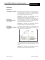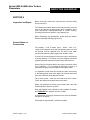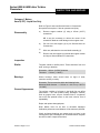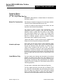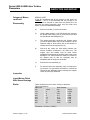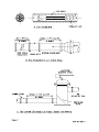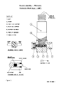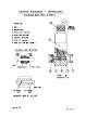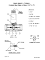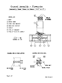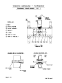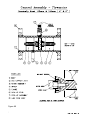
1
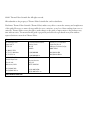
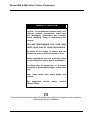
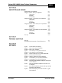
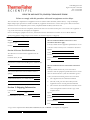
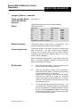
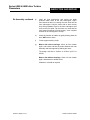
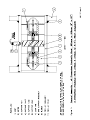
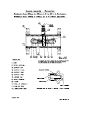
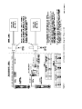
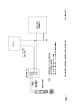
Series 6500 & 6600
Inline Turbine Flowmeters
User Guide
P/N 057-0352-002
Revision C
Part of Thermo Fisher Scientific
Series 6500 & 6600
Inline Turbine Flowmeters
User Guide
P/N 057-0352-002
Revision C
©2011 Thermo Fisher Scientific Inc. All rights reserved.
All trademarks are the property of Thermo Fisher Scientific Inc. and its subsidiaries.
Disclaimer: Thermo Fisher Scientific (Thermo Fisher) makes every effort to ensure the accuracy and completeness
of this guide. However, we cannot be responsible for errors, omissions, or any loss of data resulting from errors or
omissions. Thermo Fisher reserves the right to make changes to the guide or improvement to the product at any
time without notice. The material in this guide is proprietary and cannot be reproduced in any form without
expressed written consent from Thermo Fisher.
Process Instruments
14 Gormley Industrial Avenue
Gormley, Ontario
L0H 1G0
CANADA
Unit 702-715, 7/F Tower West
Yonghe Plaza No. 28
Andingmen East Street, Beijing
100007 CHINA
+1 (800) 437-7979
+1 (713) 272-0404 direct
+1 (713) 4573 fax
+1 (905) 888-8808
+1 (905) 888-8828 fax
+86 (10) 8419-3588
+86 (10) 8419-3580 fax
A-101, 1CC Trade Tower
Senapati Bapat Road
Pune 411 016
Maharashtra, INDIA
Ion Path, Road Three
Winsford, Cheshire
CW7 3GA
UNITED KINGDOM
1410 Gillingham Lane
Sugar Land, TX
77478 USA
+91 (20) 6626 7000
+91 (20) 6626 7001 fax
www.thermoscientific.com
+44 (0) 1606 548700
+44 (0) 1606 548711 fax
This page intentionally left blank.
Series 6500 & 6600 Inline Turbine Flowmeters
INLINE TURBINE FLOWMETERS
SERIES 6500 & 6600
HANDBOOK
Rev. C
Revision History
Issue
Description
0
CN 8653
A
Per ERO 4690
B
Per ECO 5978
C
Per ECO 7662
Thermo Fisher Scientific
Series 6500 & 6600 Inline Turbine Flowmeters
This page is blank
Thermo Fisher Scientific
Series 6500 & 6600 Inline Turbine Flowmeters
SAFETY NOTICE
Read this manual before working with the
product. For personal and system safety, and
optimum product performance, make sure
you thoroughly understand the contents
before installing, using or maintaining this
product.
YOU ARE RESPONSIBLE FOR YOUR OWN
SAFETY AND THAT OF YOUR COLLEAGUES.
Be aware of the weight of meters and the
component parts as meters increase in size.
Safety boots/shoes and eye protection must
be worn whenever bench work is undertaken.
Use lifting gear as appropriate, or, at certain
assembly or disassembly stages, enlist extra
help.
Note: some items have sharp edges and
corners.
For equipment
Thermo Fisher.
service,
please
contact
Thermo Scientific products satisfy all obligations arising from European Union legislation
to harmonise product standards.
Thermo Fisher Scientific
Series 6500 & 6600 Inline Turbine Flowmeters
This page is blank
Thermo Fisher Scientific
Series 6500 & 6600 Inline Turbine Flowmeters
SECTION 1
INTRODUCTION
INDEX
Purpose
Applicability
Other Sources of Information
Page
No.
1-1
1-1
1-2
Control of Substances Hazardous to Health
Pressure Hazards
Electrical Safety
Meter Protection
Handling
Pick-ups
Installed Protection
2-1
2-1
2-1
2-2
2-1
2-2
2-2
SECTION 2
SAFETY
SECTION 3
GENERAL DESCRIPTION
Principles of Operation
3-1
Installation
Flow Straightening
Pipe Reduction
Tanks (Liquid Applications)
Air Entrainment (Liquid Applications)
Filtration
General Notes on Pick-ups
Electrical Installation
4-1
4-1
4-1
4-2
4-2
4-2
4-3
4-5
Liquid Meters, All Sizes
Gas Meters, Sizes 12 to 64mm (0.5 to 2.5”)
Gas Meters, Sizes 100 to 508mm (4 to 20”)
5-1
5-1
5-1
SECTION 4
INSTALLATION
SECTION 5
MAINTENANCE
Index Page 1
Thermo Fisher Scientific
Series 6500 & 6600 Inline Turbine Flowmeters
INDEX
SECTION 6
INSPECTION AND REPAIR
General Notes on Construction
Category 1 Meters – 6mm (0.25”)diameter
Disassembly
Inspection
Re-assembly
Category 2 Meters – 12 to 50mm (0.5 to 2")diameter
Disassembly
Inspection
Re-assembly
Category 3 Meters – 64 to 150mm (2.5 to 6") diameter
Disassembly
Inspection
Re-assembly
Category 4 Meters – 100 to 508mm (4 to 20") diameter
Pick-ups
6-1
6-2
6-2
6-2
6-3
6-4
6-4
6-4
6-5
6-7
6-7
6-7
6-8
6-10
6-10
6-11
6-13
6-14
Pick-ups
Flowmeter And Accessories – Fault Finding Chart
7-1
7-2
Disassembly
Inspection
Re-assembly
SECTION 7
TROUBLE SHOOTING
SECTION 8
APPENDIX
Figure 1
Figure 2
Figure 2a
Figure 3
Figure 3a
Figure 4
Figure 4a
Figure 4b
Figure 5
Figure 5a
Figure 6
Figure 7
Figure 8
Figure 9
Index Page 2
Product Stream Conditioning
6mm (0.25” ) Sleeve Flowmeter
6mm (0.25” ) Flowmeter
12 to 50mm (0.5 to 2") Sleeve Flowmeter
12 to 50mm (0.5 to 2") Flowmeter
64mm to 150mm (2.5" to 6”) Sleeve Flowmeter
64mm (2.5") Gas Flowmeter
100mm to 150mm (4” and 6”) Flowmeter
100 to 508mm (4" to 20”) Sleeve Flowmeter
100 to 508mm (4" to 20”) Gas Flowmeter
Intrinsically Safe Installations, Magnetic Pick-up and
A10 Pre-Amplifier
Safe Area Installations, Magnetic Pick-up and A10
Pre-Amplifier
Non-certified Installations, Standard Pick-up and SQ2
Square Wave Pre-Amplifier
FDC1100 Frequency to Current Converter – Typical
Field Installation
Thermo Fisher Scientific
Series 6500 & 6600 Inline Turbine Flowmeters
INTRODUCTION
SECTION 1
Introduction
Purpose
This manual has been laid out to give the end user guidance on
installation, detailed maintenance procedures, and spare parts
availability.
All turbine meters require a pick-up, to provide a measurable
electrical output, and in turn there are electronic accessories
that may be connected to the pick-up output to condition or
enhance the signal for onward transmission. It should be noted
that a wide range of pick-ups is available to suit various
operating conditions, as outlined under General Description.
Applicability
The information contained in this manual is applicable to
Thermo Fisher’s in-line flowmeters fitted with sleeve or ballrace
bearings. The information is not influenced by the type of end
connection with which individual flowmeters are provided, e.g.
flanged, threaded etc.
The basic designs of the internal parts of the flowmeter vary
with nominal size. As a result of this, for the purposes of
describing maintenance procedures, the meters have been
divided into four categories, as follows:
Category 1
Category 2
Category 3
Category 4
6mm
12 to 50mm
64mm to 150mm
100 to 508mm
(0.25”)
(0.5" to 2")
(2.5" to 6")
(4" to 20")
In the case of 100 to 150mm (4" to 6") meters two design types
exist, one of which will be superseded. Maintenance
procedures for each option are included in this manual.
Section 1 Page 1 of 2
Thermo Fisher Scientific
Series 6500 & 6600 Inline Turbine Flowmeters
Other Sources Of
Information
INTRODUCTION
For specific details of meter types available, operating ranges,
special applications, accessories, physical dimensions etc,
reference should be made to the current product datasheets.
If there are any doubts regarding the proposed use or
installation of the meter/s supplied, please contact Thermo
Fisher.
Technical Notes are available containing detailed performance
specifications and application requirements for all types of
turbine meter. For Inline Meters fitted with sleeve bearings the
following publications are available:
Technical Note 003:
Inline Flowmeter Application Guide.
Technical Note 005:
Inline Flowmeter Calibration and
Performance Specifications
Thermo Fisher offers a full service and calibration facility.
Calibration is offered as a separate service if required.
Section 1 Page 2 of 2
Thermo Fisher Scientific
Series 6500 & 6600 Inline Turbine Flowmeters
SAFETY
SECTION 2
Safety – Important Notice
Control Of Substances
Hazardous To Health
Many metering installations involve the measurement of
hazardous fluids. Before removal from service it is important to
ensure that the COSHH data is available and appropriate
protective measures are taken.
In addition there may be site specific procedures relating to
protective clothing and hazard handling. Ensure that such
procedures are adhered to.
Pressure Hazards
An inline flowmeter is considered as a pressure piping
component as defined by the Pressure Equipment Directive.
Care must be exercised to ensure that the line section is
isolated, drained and relieved of pressure before the meter is
removed. Before installing new equipment check that the
instrument service limits are compatible with the line conditions
in to which the meter is to be placed in service. The customer
is responsible for ensuring that all equipment is protected
against over-pressurisation, including that caused by external
fire.
Electrical Safety
Before starting any work, ensure that the power connections
are isolated and precautions are taken to prevent power being
restored whilst work is taking place. Particular attention should
be paid to installation conditions specified for hazardous areas.
Such installations forbid the use of tools or equipment which
could produce an explosion hazard.
Meter Protection
Handling
DO NOT subject the meter or the pick-up to excessive shock
loading - never use hammers or mallets. Shock loading can
shatter tungsten carbide parts in the meter internals. Neither
should foreign bodies - dirt, swarf etc be allowed to enter the
meter bore or the pick-up cavity.
N.B. Surface damage to any of the meter internal parts can
affect its performance.
DO NOT use air lines or hoses - any pressured source of
air/gas or liquid - to check or clean a flowmeter. (It may be
ultrasonically cleaned). The danger is that rotor over-speed
may occur.
If a rotor is allowed to over-speed serious bearing damage may
occur.
Section 2 Page 1 of 2
Thermo Fisher Scientific
Series 6500 & 6600 Inline Turbine Flowmeters
Pick-ups
SAFETY
If required these are easily removed for inspection, access
maintenance etc. All pick-ups have a male thread that engages
with a female threaded flat-bottomed hole.
In order to detect the passage of rotor blades, the end face of
the pick-up has to be close to the rotor, therefore, the bottom of
the pick-up hole is a thin section of the meter body material.
Pick-ups are a "finger tight" fit only. NEVER try to tighten
further.
On some models a locking ring is fitted (the same rule applies –
locking rings should be finger tight only) - usually where,
because the meter is small, the well thread depth is limited.
Installed Protection
The notes in ‘Handling’ still apply. However, the following
additional precautions should be observed:
AVOID sudden shocks e.g. sudden filling of the process line
with a liquid. The trapped air will cause rapid acceleration of the
turbine and potential overspeeding. ALWAYS introduce a liquid
slowly (relate to the meter range and DO NOT exceed its
normal maximum flowrate).
Section 2 Page 2 of 2
Thermo Fisher Scientific
1410 Gillingham Lane
Sugar Land, TX 77478 USA
Tel: 713.272.0404
Fax: 713.272.2272
HEALTH AND SAFETY (COSHH) CLEARANCE FORM
Failure to comply with this procedure will result in equipment service delays.
This form must be completed for all equipment returned to Thermo Fisher Scientific (Thermo Fisher) – Sugar Land Depot
Repair. Depot repair personnel are unable to handle any equipment that has been in contact with a process fluid or hazardous
material if it is not accompanied by this correctly completed Health and Safety Clearance Form.
All sections of this form must be completed, and the form must arrive at Thermo Fisher prior to the arrival of the equipment. A
copy of this form must also accompany the equipment.
Prior to returning any equipment for service, authorization must be obtained from customer service. A Return Material
Authorization (RMA) number will be issued and must be entered in Section 1 of this form.
Section 1: Reference Details
Section 4: Declaration
RMA #:
Must be authorized ONLY if non-toxic or nonhazardous substances apply.
Equipment type:
Serial #:
I hereby confirm that the equipment specified above has not
come into contact with any toxic or hazardous substances.
Section 2: Process Fluid Information
Signed:
All substances in contact with the equipment must be
declared.
Name:
Position:
For/on behalf of:
Chemical names (list all):
Date:
Precautions to be taken when handling these substances (list
all):
Must be authorized if toxic or hazardous substances
apply.
Action to be taken in the event of human contact or
spillage:
I hereby confirm that the only toxic or hazardous
substances that the equipment specified has been in contact
with are named in Section 2, that the information given is
correct, and that the following actions have been taken:
Additional information you consider relevant:
1.
The equipment has been drained and flushed.
2.
The inlet/outlet ports have been sealed, and the
equipment has been securely packed and labeled.
3.
The carrier has been informed of the hazardous nature
of the consignment and has received a copy of this
completed form.
Section 3: Shipping Information
Carrier details:
Tel:
/ Fax:
Signed:
Scheduled delivery date to Thermo Fisher:
Name:
Position:
For/on behalf of:
Date:
A copy of this completed form MUST BE HANDED TO THE CARRIER to accompany the equipment.
Form No.: QF_COSHH
ECO: 5424
REV: B
Date 12-08-06
This page intentionally left blank.
Series 6500 & 6600 Inline Turbine
Flowmeters
GENERAL DESCRIPTION
SECTION 3
General Description
Principles of Operation
The turbine flowmeter is essentially a velocity-measuring
device, which is calibrated to indicate volumetric flow of liquid or
gas in a pipeline. The operation of the flowmeter is based upon
the speed (angular velocity) of a freely supported rotor, which
revolves at a rate directly proportional to the flow rate of the
medium.
The rotor blades cut a magnetic field set up by a permanent
magnet assembly which is installed in a pick-up unit.
The pick-up is constructed of a coil placed adjacent to a
permanent magnet and wound on to a former. The former is
positioned over a ferromagnetic core, which is arranged such
that it is close to a turbine meter rotor blade when passed
beneath.
The design of pick-up bodies is standard, with variations on
material or length. They all have male threaded ends, which
either screw directly into the meter body, or into a welded stub
which has a mating internal thread.
The change in flux density resulting from the passage of rotor
blades induces a voltage across the coil. The generated
frequency is proportional to the speed of the rotor. The number
of pulses per unit volume is established during calibration and
is termed "The Calibration Constant". The variation of this
constant over a specified rate of flow range is defined as the
meter linearity.
The pulses are fed to appropriate electronic units or computer
interface cards for processing to provide totalised and rate of
flow readouts.
The pulse density (number of pulses per rotor revolution)
depends on the number of rotor blades.
It is generally desirable to have as high a pulse density as
possible to increase the resolution of measurement, increasing
the pulse density by increasing the number of rotor blades is
only possible within certain limits.
This effect, where it exists, is overcome by "shrouding" the rotor
(fitting a rim) into which are embedded slugs of ferromagnetic
material at regular intervals around the periphery.
Section 3 Page 1 of 2
Thermo Fisher Scientific
Series 6500 & 6600 Inline Turbine
Flowmeters
GENERAL DESCRIPTION
This page is blank
Section 3 Page 2 of 2
Thermo Fisher Scientific
Series 6500 & 6600 Inline Turbine Flowmeters
INSTALLATION
SECTION 4
Installation
The Thermo Scientific range of turbine flowmeters has been
designed to give high accuracy with long term stability and
operating life. To ensure this it is recommended that the
following points be considered during installation.
All meters have the "Direction of Flow" marked on the body.
Incorrect flow direction will produce an installed calibration
error.
Flow Straightening
The main requirement for turbine meter flow measurement is
repeatability i.e. for any particular flow rate the same number
of pulse per unit volume is obtained. This can only be
achieved if the liquid or gas is flowing smoothly and fully
"axially" in the pipe (i.e. there is no "swirl" or flow pulsation).
If the upstream pipe work, for a distance of at least twenty
pipe diameters, has no fittings such as valves (other than full
flow gate or ball valves) or bends, other than large radius, tees
etc, then a minimum length of clean bore pipe of ten flowmeter
pipe diameters should be provided immediately upstream of
the meter.
Wherever any fittings or pumps are installed upstream of the
meter, then a length of pipe of twenty diameters should be
provided.
The best practice is to use a Thermo Scientific flow
straightener as illustrated in Figure 1(A) (see Appendix).
Downstream conditions can "reflect back" on a meter. Usually
it is satisfactory to halve the straightener pipe lengths stated
above. The API manual of flow measurement recommends 10
diameters of straight pipe upstream and 5 diameters
downstream as a minimum.
Pipe Reduction
A turbine meter is sized to accommodate a rate of flow range
and not necessarily to match a given pipe size. It is thus often
the case that pipe reduction is required prior to installing the
meter.
Reducers should be installed with a minimum of 10 diameters
of straight pipe (of meter diameter) upstream and 5 diameters
downstream of the meter.
Reducers should be tapered cone sections where possible.
(See Figure 1(B).)
Section 4 Page 1 of 6
Thermo Fisher Scientific
Series 6500 & 6600 Inline Turbine Flowmeters
INSTALLATION
Tanks
(Liquid Applications)
Where the flowmeter is installed in a line fitted to the bottom of
a storage vessel it is advisable to fit a baffle plate over the
hole in the tank in order to prevent the liquid vortexing through
the flowmeter. (See Figure 1(C).)
Air Entrainment (Liquid
Applications)
For liquid applications air entrainment is to be avoided. Where
it is possible that air could be present in the line an air
eliminator may be fitted as illustrated in Figure 1(C).
In custody transfer applications it is imperative that all air
entrainment be removed from the liquid before it reaches the
flowmeter. This can be achieved by fitting an Air/Gas
Separator. (See Figure 1(C).)
Filtration
Liquid Meters With
Sleeve Bearing
Extremely fine filtration is not required with sleeve bearings,
however, a coarse filter should be fitted upstream of the
flowmeter for protection against damage by pipe scale,
welding splatter and other foreign material.
Recommended filter mesh sizes are as follows:
Liquid And Gas Meters
With Ballrace Bearing
Meter size
mm
Meter size
inches
Perforation
size
Mesh size
6mm to 12mm
16mm to 25mm
38mm to 64mm
100mm to 150mm
203mm to 406mm
0.25” to 5”
0.625" to 1"
1.5" to 2.5"
4.0" to 6.0"
8.0" to 16.0"
0.12mm
0.2mm
0.5mm
2.0mm
5.0mm
120
80
40
10
4 or 6
Good filtration is recommended for meters fitted with ballrace
bearings for liquid or gas use.
Recommended filter sizes are as follows:
Section 4 Page 2 of 6
Meter size
mm
Meter size
inches
Perforation size
6mm to 12mm
16mm to 25mm
38mm to 64mm
100mm to 150mm
203mm to 406mm
0.25” to 5”
0.625" to 1"
1.5" to 2.5"
4.0" to 6.0"
8.0" to 16.0"
5 micron
10 micron
20 micron
50 micron
200 micron
Thermo Fisher Scientific
Series 6500 & 6600 Inline Turbine Flowmeters
INSTALLATION
General Notes Regarding Turbine meters often have more than one pick-up. After
installing the turbine meter in the process line, if the pick-ups
Pick-Ups
are available, fit them in order to protect the wells into which
they fit.
All "standard" flowmeters leave Thermo Fisher with at least
one pick-up. In special applications more than one pick-up
may be supplied, eg.:
(a) Custody transfer/pulse security checking requires
two pick-ups, usually 90° displaced in electrical
phase relationship.
(b) Where a third pick-up is fitted for meter proving.
(c) Two pick-ups are used with bi-directional turbine
meters, and the direction of flow is derived from
the phase difference between the outputs.
Pick-ups are easily removed for installation, access
maintenance etc. NB. All pick-ups have a male thread that
engages with a female threaded blind hole. In order to detect
rotor blades, the end face of the pick-up hole is constructed as
a thin membrane of the meter body material. Pick-ups are a
"finger tight" fit only. NEVER try to tighten further.
On some models a locking ring is fitted - usually where,
because the meter is small, the well thread depth is limited.
The same rule applies – locking rings should be finger tight
only.
The pick-up signal output amplitude and frequency range is
dependent on the meter size. As a guide, for a standard pickup, typical figures apply over the standard flow range:
(See following page for table)
Section 4 Page 3 of 6
Thermo Fisher Scientific
Series 6500 & 6600 Inline Turbine Flowmeters
INSTALLATION
TYPICAL PICK-UP SIGNAL OUTPUT
Meters fitted with sleeve bearings (liquid use only)
Category 1
6mm (.25”)
Frequency: 130 to 1300Hz
Amplitude: 10 to 100mV RMS
Category 2
12mm to 25mm (.5” to 1”)
Frequency: 130 to 1300Hz
Amplitude: 30 to 300mV RMS
Category 2
38mm to 50mm (1.5” to 2”)
Frequency: 50 to 500 Hz
Amplitude: 40 to 400 mV RMS
Category 3
64mm to 150mm (2.5” to 6”)
un-shrouded rotor
Frequency: 50 to 500 Hz
Amplitude: 40 to 400 mV RMS
Category 3
64mm to 150mm (2.5” to 6”)
shrouded rotor
Frequency: 120 to 1200 Hz
Amplitude: 15 to 150 mV RMS
Category 4
100mm to 508mm (4” to 20”)
shrouded rotor
Frequency: 120 to 1200Hz
Amplitude: 15 to 150 mV RMS
Meters fitted with ballrace bearings (clean liquid and gas use)
Category 1
6mm (.25”)
Liquid meter only
Frequency: 130 to 1300Hz
Amplitude: 10 to 100mV RMS
Category 2
12mm to 25mm (.5” to 1”)
Liquid meter
Frequency: 130 to 1300Hz
Amplitude: 30 to 300mV RMS
Gas meter
Frequency: 240 to 2400Hz
Amplitude: 30 to 300mV RMS
Category 2
38mm to 50mm (1.5” to 2”)
Liquid meter
Frequency: 50 to 500 Hz
Amplitude: 40 to 400 mV RMS
Gas meter
Frequency: 175 to 1750Hz
Amplitude: 40 to 400mV RMS
Category 3
64mm to 150mm (2.5” to 6”)
Liquid meter
Frequency: 50 to 500 Hz
Amplitude: 40 to 400 mV RMS
Gas meter
Frequency: 150 to 1500Hz
Amplitude: 50 to 500mV RMS
Section 4 Page 4 of 6
Thermo Fisher Scientific
Series 6500 & 6600 Inline Turbine Flowmeters
Category 4
100mm to 508mm (4” to 20”)
Electrical Installation
INSTALLATION
Liquid meter
Frequency: 40 to 400Hz
Amplitude: 50 to 500V RMS
Gas meter
Frequency: 160 to 1600Hz
Amplitude: 100 to 1000V RMS
Because of the nature of the output signal and in particular its
susceptibility to noise, screened twisted cable should be used
properly earthed. If the distance between the flowmeter and
signal conditioning electronics exceeds 200 metres (650ft), an
ISA 10 pre-amplifier should be fitted. (See Appendix, Figures 6
and 7.)
Utilize approved Class 1 Division 1 explosion proof wiring
methods.
Section 4 Page 5 of 6
Thermo Fisher Scientific
Series 6500 & 6600 Inline Turbine Flowmeters
INSTALLATION
This page is blank
Section 4 Page 6 of 6
Thermo Fisher Scientific
Series 6500 & 6600 Inline Turbine Flowmeters
MAINTENANCE
SECTION 5
Maintenance
Liquid Meters, All Sizes
No maintenance can be carried out on the internal parts of this
type of meter whilst it is in operation. The only maintenance is
to the external parts of the meter i.e. electrical enclosures,
electrical signal conditioning units and circuits.
REMEMBER TO ISOLATE ALL ELECTRICAL SUPPLIES
BEFORE CARRYING OUT MAINTENANCE WORK
Gas meters
Sizes 12mm to 64mm
( 0.5” to 2.5”)
No maintenance can be carried out on the internal parts of this
type of meter whilst it is in operation. The only maintenance is
to the external parts of the meter i.e. electrical enclosures,
electrical signal conditioning units and circuits.
REMEMBER TO ISOLATE ALL ELECTRICAL SUPPLIES
BEFORE CARRYING OUT MAINTENANCE WORK
Gas Meters
Sizes 100mm to 508mm
(4” to 20”)
No maintenance can be carried out on the internal parts of this
type of meter whilst it is in operation except for lubrication of the
meters bearings via the lubrication tube.
The only other maintenance is to the external parts of the meter
i.e. electrical enclosures, electrical signal conditioning units and
circuits.
REMEMBER TO ISOLATE ALL ELECTRICAL SUPPLIES
BEFORE CARRYING OUT MAINTENANCE WORK
Section 5 Page 1 of 1
Thermo Fisher Scientific
Series 6500 & 6600 Inline Turbine Flowmeters
MAINTENANCE
This page is blank
Section 5 Page 2 of 2
Thermo Fisher Scientific
Series 6500 & 6600 Inline Turbine
Flowmeters
INSPECTION AND REPAIR
SECTION 6
Inspection and Repair
Before removing a meter from a process line, read the Safety
notes in section 2.
The following procedures assume the meter has been removed
from the line and that a clean working area is available, with a
clean high-density rubber/polyurethane or similar covering.
Covering should be non-splinter, non-powdering etc.
Before attempting any disassembly, please study the relative
General Assembly Drawing (Figures 2-5)
General Notes on
Construction
The category 1 and 2 meters (6mm - 50mm / 0.25” to 2”
inclusive) are designed such that sub-assembly parts can only
be removed from the upstream end. The body of the meter
provides the positioning stops against the direction of flow.
A close fit of the end supports in the meter body is achieved by
a honing operation. For removal, front end-supports should be
gripped by parallel motion pliers (plain faces) and pulled out.
Where fitting new supports that for any reason have been found
to be "undersize" - i.e. not capable of achieving a tight fit, it is
permissible to lightly peen the edges of the support vanes.
It is important to treat each vane equally (to retain concentricity
of the bearing/shaft centre with respect to the body bore) and
peen with a flat face small diameter hammer.
Tap at three points - near the vane ends and at the centre.
"Draw" the material using both faces of the vanes.
Where new supports are found to be oversize each vane may
be filed equally to achieve a good fit.
Rear end supports may be drifted out using a plastic or wooden
drift TOWARDS the upstream end of the meter.
A small amount of free play movement in the rotors is allowable
and part of the design.
All threads are right handed - clockwise to tighten.
Section 6 Page 1 of 14
Thermo Fisher Scientific
Series 6500 & 6600 Inline Turbine
Flowmeters
INSPECTION AND REPAIR
Category 1 Meters
6mm (0.25”) Liquid Use Only
Refer to Figure 2 and read General Notes on Construction.
No special tools required. Start at upstream end (inlet).
Disassembly
a)
Remove support retainer (5) using a 9.5mm (0.375”)
screwdriver.
NB It may be necessary to relieve the centre of the
screwdriver blade to avoid damage to the support nose.
b)
Pull out front end support (3) as per General Notes on
Construction.
c)
With care, withdraw the rotor and shaft assembly (2).
d)
Remove rear end support (4) towards the support retainer
end as per General Notes on Construction.
Inspection
Shafts
Tungsten carbide or stellite pinion. These should be free from
wear, scoring or abrasion.
Dimension: 1.93mm (0.0760”) diameter
Tolerance: - 0.01mm (- 0.0005”)
Bearings
Sleeve bearings: these should show no signs of wear,
excessive scoring or ovality.
Dimension: The bore must be within the following limits:
Measured shaft diameter: + 0.05 mm to + 0.01 mm (+ 0.002” to
+ 0.0005”)
General Appearance
The surface condition of all parts in the liquid flow can affect
performance – the main problem being "damaged" surfaces,
such as gouges, burrs, cuts etc. Surface finish or "roughness"
has much less potential effect on the main criterion, that of
repeatability.
Reject and replace damaged parts.
Rotor blades must not be bent or otherwise damaged.
Calibration performance and balance will be adversely affected.
Check end-stone bearings are present and not loose in the
end-supports, split or damaged. An illuminated bench magnifier
should be used to inspect these items.
Section 6 Page 2 of 14
Thermo Fisher Scientific
Series 6500 & 6600 Inline Turbine
Flowmeters
INSPECTION AND REPAIR
Category 1 Meters continued
a)
Select the rear end-support. Note this has a smaller
overall diameter than the front end-support assembly.
b)
Insert the rear end-support carefully, using if necessary
a soft drift and rubber mallet – the drift should be
almost full bore diameter (do not use punches). It may
be necessary to file a small lead in chamfer on the
edge of the vanes to ensure correct positioning in the
downstream bore. See General Notes on Construction
if in doubt about the fit.
Re-assembly
Support vane orientation – insert the rear end-support
such that two vanes are orientated at roughly 45°
each, to the centre line of the pick-up, i.e. with the
centre line of the meter and pick-up vertical, the vanes
are positioned as an "X".
c)
Fit the rotor and shaft (for gas meters rotor, shaft and
bearing) assembly into the bore. Note the rotor blades
have a leading edge and a trailing edge and must be
installed in a particular direction - refer to Figure 2.
Do not attempt to "force" the rotor shaft into the rear
end support – gentle guidance only should be used.
Shaft ends are chamfered
d)
Insert the front end-support and ensure the blade
positions match those of the rear support.
Again, care should be taken in positioning the rotor
shaft into the front end-support. Hold the meter with its
bore vertical, entry facing upwards. Ease in the front
end-support until close to the rotor shaft. Tip the meter
over such that the rotor drops forward into its front
bearing – then complete insertion of the end support to
its stop.
Section 6 Page 3 of 14
e)
Check the freedom of rotation by gently blowing down
the bore, NOT with an airline.
f)
Screw in the support retaining nut and tighten up to a
torque value of 5ftlbf (7nm).
g)
Check for free rotation again, and ensure end float
between the rotor assembly and end-support is present
by shaking the meter. The design end float is 0.25 to
0.75mm (0.010” to 0.030”).
h)
Calibrate or reinstall as required.
Thermo Fisher Scientific
Series 6500 & 6600 Inline Turbine
Flowmeters
INSPECTION AND REPAIR
Category 2 Meters
12mm to 50mm (0.5 to 2”)
Liquid and Gas Use
Disassembly
No special tools required. Start at upstream end (inlet). Refer
to Figure 3 and General Notes on Construction.
a)
Remove circlip (5). Note: the 6800 series meter has a
circlip at both ends, but only one needs to be removed
to enable the capsule to be removed.
b)
c)
d)
Pull out front end support (3).
With care, extract the rotor and shaft assembly (2).
Remove rear end support (4) towards the circlip end of
the meter, as per General Notes on Construction.
Inspection
Liquid Meters Fitted
With Sleeve Bearings
Shafts
These should be free from wear, scoring or abrasion.
Table of dimensions:
Meter size
Shaft diameter
Mm
inches
mm
Inches
12
0.5
1.93
0.0760
15
0.625
1.93
0.0760
18
0.75
2.77
0.1094
25
1.0
2.77
0.1094
37
1.5
4.77
0.1850
50
2.0
6.35
0.2500
Tolerances - 0.01mm (- 0.0005”)
Sleeve Bearings
These should show no signs of wear, excessive scoring or
ovality
Dimension: The bore must be within the following limits:
Measured shaft diameter: + 0.05 mm to + 0.01 mm (+ 0.002” to
+ 0.0005”)
Check end-stones are present and not loose, split or damaged.
General appearance
Section 6 Page 4 of 14
The surface condition of all parts in the liquid flow can affect
performance – the main problem being "damaged" surfaces,
such as gouges, burrs, cuts etc. Surface finish or "roughness"
has much less potential effect on the main criterion, that of
repeatability. The rotor blades must not be bent or otherwise
damaged. Calibration performance and balance will be
adversely affected. Reject and replace damaged parts.
Thermo Fisher Scientific
Series 6500 & 6600 Inline Turbine
Flowmeters
INSPECTION AND REPAIR
Category 2 Meters – Inspection
Liquid and Gas Meters
Fitted With Ballrace
Bearings
Shafts
See Figure 3a.
These should be free from wear, scoring or abrasion.
Table of Dimensions:
Meter size
Shaft diameter
mm
inches
mm
inches
12
0.5
1.20
0.0469
15
0.625
1.20
0.0469
18
0.75
1.98
0.0781
25
1.0
1.98
0.0781
37
1.5
6.35
0.2500
50
2.0
6.35
0.2500
Tolerances - 0.01mm (- 0.0005”)
Ballrace Bearings
These should show no signs of wear or contamination. They
should be replaced if any deterioration is suspected.
General Appearance
The surface condition of all parts in the liquid or gas flow can
affect performance - the main problem being "damaged"
surfaces, such as gouges, burrs, cuts etc. Surface finish or
"roughness" has much less potential effect on the main
criterion, that of repeatability.
Reject and replace damaged parts. Rotor blades must not be
bent or otherwise damaged. Calibration performance and
balance will be adversely affected.
Re-Assembly
Section 6 Page 5 of 14
a)
Select the rear end-support. This has a smaller overall
diameter than the front support assembly.
b)
Insert rear end-support carefully, using if necessary a
soft drift and rubber mallet - the drift should be almost
full bore diameter - do not use punches.
Support vane positioning - insert the rear end support
such that two vanes are at roughly 45° each with
respect to the centre line of the pickup well, i.e. with the
centre line of the meter and pick-up vertical, the vanes
are positioned as an “X”.
c)
Fit the rotor and shaft assembly into the bore. The
rotor blades have a leading edge and a trailing edge
and must be installed in a particular direction - refer to
Figure 3). Do not attempt to "force" the rotor shaft
into the rear end-support - gentle guidance only should
be used. Shaft ends are tapered.
Thermo Fisher Scientific
Series 6500 & 6600 Inline Turbine
Flowmeters
Re-Assembly continued
INSPECTION AND REPAIR
d)
Insert the front end-support and ensure the blade
positions match those of the rear end-support. Again,
care should be taken in inserting the rotor shaft into the
front end-support. Hold the meter with its bore vertical,
entry facing upwards. Ease in the front end-support until
close to the rotor shaft. Tip the meter over such that the
rotor drops forward into its front bearing - then complete
insertion of the end-support to its stop.
e)
Check the freedom of rotation by gently blowing down the
bore, NOT with an airline.
f)
Fit the support retaining circlip.
g)
Meters with sleeve bearings: Check for free rotation
again, and ensure end float is present between the rotor
assembly and end-supports by shaking the meter.
The design end float is 0.25mm to 0.75mm (0.010” to
0.030”).
Meters with ballrace bearings: Check for free rotation
again, and absence of audible noise.
Calibrate or reinstall as required.
Section 6 Page 6 of 14
Thermo Fisher Scientific
Series 6500 & 6600 Inline Turbine
Flowmeters
INSPECTION AND REPAIR
Category 3 Meters – REMINDER: Read Section 6, General Notes On Construction,
64mm to 150mm (2.5 to and refer to Figure 4.
6”) Liquid and Gas Use
Disassembly
General note on construction:
For liquid meters the rotor end-supports are identical. They are
also removable from the end they "face", front end from the inlet
end, rear end from the downstream end. For gas meters
100mm and 150mm (4” and 6”) the rear end-support has
provision for the lubricating tube.
TOOL REQUIRED: Part No: TOOL/001 100mm (4”) meter) /
002 150mm (6” meter)
The circlip is a spirolox retaining ring - it will spiral into the
groove by hand; removal is by using a screwdriver - the ring
has a notch or slot to start the "unspiralling" out of the groove.
Recommended screwdriver is plastic handle (electrician’s type)
with long reach blade.
a)
Remove circlip – front end support (4)
b)
With the meter supported in a vertical position, front
end uppermost, remove front bearing support (2).
Note: for 100mm and 150mm (4” and 6”) meters use
the removal tool (TOOL/001)
c)
Remove the rotor and shaft assembly
d)
Reverse position of the meter
e)
Remove circlip - rear end support (4)
f)
Remove rear end-support (2).
NOTE: 100mm and 150mm (4” and 6” meters) used on
gas have a lubrication tube assembly which must be
removed before the rear end-support is removed.
Section 6 Page 7 of 14
Thermo Fisher Scientific
Series 6500 & 6600 Inline Turbine
Flowmeters
INSPECTION AND REPAIR
Category 3 Meters Continued
Inspection
Liquid Meters Fitted
With Sleeve Bearings
Shafts
These should be free from wear, scoring or abrasions.
Dimensions:
Diameter
2.5" meter: 6.35mm (0.25”)
Tolerance: - 0.01mm (- 0.0005”)
4" meter: 7.94mm (0.312”) Tolerance: - 0.02mm (- 0.001”)
6" meter: 9.52mm (0.375”) Tolerance: - 0.02mm (- 0.001”)
Sleeve Bearings
These should show no signs of wear, excessive scoring or
ovality.
Dimension: The bore must be within the following limits:
Measured shaft diameter: + 0.05 mm to + 0.01 mm (+ 0.002” to
+ 0.0005”)
General Appearance
The surface condition of all parts in the liquid flow can affect
performance - the main problem being “damaged” surfaces,
such as gouges, burrs, cuts etc. Surface finish or "roughness"
has much less potential effect on the main criterion, that of
repeatability. The rotor blades must not be bent or otherwise
damaged. Calibration performance and balance may be
adversely affected.
Reject and replace damaged parts.
Check end-stones (or in the case of the 100mm and 150mm /
4" and 6" sizes, thrust balls) are not loose, split or otherwise
damaged.
Inspection
Liquid And Gas Meters
Fitted with Ballrace
Bearings
See Figure 4a)
Shafts
These should be free from wear, scoring or abrasions.
2.5" meter: 6.35mm (0.25”)
4" meter: 7.94mm (0.312”)
6" meter: 9.52mm (0.375”)
Section 6 Page 8 of 14
Tolerance: - 0.01mm (- 0.0005”)
Tolerance: - 0.02mm (- 0.001”)
Tolerance: - 0.02mm (- 0.001”)
Thermo Fisher Scientific
Series 6500 & 6600 Inline Turbine
Flowmeters
INSPECTION AND REPAIR
Category 3 Meters Continued
Ballrace Bearings
These should show no signs of wear or excessive play. If
deterioration is suspected renew as a matter of course.
General Appearance
The surface condition of all parts in the fluid flow can affect
performance - the main problem being “damaged” surfaces,
such as gouges, burrs, cuts etc. Surface finish or "roughness"
has much less potential effect on the main criteria, that of
repeatability. The rotor blades must not be bent or otherwise
damaged. Calibration performance and balance may be
adversely affected.
Reject and replace damaged parts.
Re-Assembly
For liquid meters and 64mm (2.5”) gas meters, both endsupports are identical. NOTE: For liquid meters with sleeve
bearings, if some end-stone wear is discovered in the support
that was at the rear (downstream) end, the two can be
reversed. Most wear of course will occur on the downstream
stone.
For gas meters 100mm and 150mm (4” and 6”) the rear endsupport has provision for a lubrication tube.
a)
Insert rear end-support to the shoulder depth and
ensure that it is correctly seated. Fit the lubrication
tube assembly (100mm and 150mm / 4” & 6” gas
meters only).
b)
Fit rear circlip and ensure that it is correctly seated.
c)
Ease the rotor and shaft assembly into the bore, and
feed the shaft into the sleeve. Ensure the rotor is facing
the correct way - enter trailing edge first.
d)
Fit the front end-support with care, and ensure the shaft
correctly enters the sleeve.
e)
Fit front circlip and ensure that it is correctly seated.
f)
Meters with sleeve bearings: Check the rotor has end
float and rotates freely.
The design end float is 0.64 to 1.20mm (0.025 to
0.050”) .
g)
Section 6 Page 9 of 14
Calibrate or re-install as applicable.
Thermo Fisher Scientific
Series 6500 & 6600 Inline Turbine
Flowmeters
INSPECTION AND REPAIR
Category 4 Meters
100mm To 508mm
(4" - 20") Liquid And Gas Use
REMINDER: Read Section 6, General Notes On Construction,
and refer to Figure 5.
Notes On Construction
This category comprises the largest of the total range available.
There are some fundamental differences to note:
In order to increase the pulse output per unit volume, the rotor
may have a shroud around its periphery.
The shroud is used to house small ferromagnetic slugs
equispaced around its periphery, such that the number of
magnetic inserts is greater than the number of rotor blades,
thus giving better resolution as a result of the higher pulse
density so achieved. There are occasions where shrouds are
fitted for a different purpose, such as to improve linearity
performance under conditions of high viscosity.
100mm and 150mm / 4" and 6" meters may be supplied to this
design as well as the previous category as described.
Intrusive pick-ups
Liquid Meters Only
Some users may find early models of these flowmeters which
were fitted with an ‘intrusive style’ pick-up which penetrated
through the flowmeter body and picked up pulses from a
‘phonic wheel’ mounted at the side of the rotor. For these
models it is necessary to remove the pick-up and shims before
attempting to remove the internals. On re-assembly care must
be taken to ensure that the pick-up hole in the support tube and
body are aligned with the phonic wheel to permit fitting of the
pick-up.
For liquid meters only, bearings are lubricated by the process
medium. An orifice in the nose of the rotor support nut, (3)
allows the flow of liquid through the end support assembly (8) to
the bearings. The bearings, being manufactured from tungsten
carbide will function correctly even if the flowing medium has no
lubricating properties.
For gas meters, a lubrication tube is fitted (see Figure 5a).
The rotor support structures, front and rear, are identical. They
are multi-piece sub-assemblies and self-centring and locking,
when the support nut is tightened. This is achieved by tapered
slots in the end support tube, to which the vanes (three per
end) slide and are forced against the bore of the meter body.
Section 6 Page 10 of 14
Thermo Fisher Scientific
Series 6500 & 6600 Inline Turbine
Flowmeters
Category 4 Meters
continued
Disassembly
INSPECTION AND REPAIR
SPECIAL NOTE:
It can be considered that all the meters in this range are
"HEAVY" - thus it is recommended that the pick-ups if not
removed prior to removal of meter from the process line, are
removed and stored physically away from the meter work
station, to prevent inadvertent damage.
a)
Remove lock tabs (7) each end of meter.
b)
Using a plate spanner or soft drift loosen then unscrew
the slotted front bearing nut (3) and remove that plus
the shouldered centralising disc (4).
c)
The support assembly comprising the location vanes
(6) held in tapered slots may now be released. Tap the
upstream edge of these vanes with a soft hammer to
release them from the support tube (5).
d)
Note that the vanes are held axially between two
narrow shoulders machined in the body bore. The
support tube and blades must be loose before
withdrawal is attempted, as shoulder edges must not be
damaged. The vanes should be drawn out relative to
the support tube so that the assembly may be
withdrawn past the body bore shoulders.
e)
Remove the rotor assembly (2).
f)
For removal of the rear assembly, carry out steps (b) to
(d) inclusive. For gas meters remember to remove the
lubrication tube assembly before loosening the support
vanes as previously described.
Inspection
Liquid Meters Fitted
With Sleeve Bearings
Shafts
These should be free from wear, scoring or abrasions.
Table of dimensions:
Meter size
Shaft diameter
mm
inches
mm
inches
100
4
7.93
0.3125
150
6
9.52
0.375
200
8
12.7
0.500
250
10
12.7
0.500
300
12
19.05
0.750
400
16
19.05
0.750
500
20
19.05
0.750
Tolerances - 0.01mm (- 0.0005”)
Section 6 Page 11 of 14
Thermo Fisher Scientific
Series 6500 & 6600 Inline Turbine
Flowmeters
INSPECTION AND REPAIR
Category 4 Meters
Continued
Sleeve Bearings
These should show no signs of wear, excessive scoring or
ovality.
Dimensions: The bore must be within the following limits:
Measured shaft diameter: + 0.15 mm (+ 0.006") 202mm (8")
and above, + 0.10 mm (+ 0.004") 150mm (6") and below.
General Appearance
The surface condition of all parts in the liquid flow can affect
performance - the main problem being "damaged" surfaces,
such as gouges, burns, cuts etc. The rotor blades must not be
bent or otherwise damaged. Calibration performance and
balance may be adversely affected.
Replace any damaged parts.
In each end support assembly and directly behind the sleeve
bearings, is a separate end-stone thrust plate. Check this for
excessive centre wear, or damage etc.
Inspection
Liquid And Gas Meters
Fitted With Ballrace
Bearings
See Figure 5a.
Shafts
These should be free from wear, scoring or abrasions.
Table of dimensions:
Meter size
Shaft diameter
mm
inches
Mm
100
4
7.93
150
6
9.52
200
8
12.7
250
10
12.7
300
12
19.05
400
16
19.05
500
20
19.05
Tolerances - 0.01mm (- 0.0005”)
Ballrace Bearings
Section 6 Page 12 of 14
Inches
0.3125
0.375
0.500
0.500
0.750
0.750
0.750
These should show no signs of excessive play. If deterioration
is suspected, replace as a matter of course.
Thermo Fisher Scientific
Series 6500 & 6600 Inline Turbine
Flowmeters
Category 4 Meters
Continued
General Appearance
INSPECTION AND REPAIR
The surface condition of all parts in the liquid or gas flow can
affect performance - the main problem being "damaged"
surfaces, such as gouges, burrs, cuts etc. Surface finish or
"roughness" has much less potential effect on the main
criterion, that of repeatability. The rotor blades must not be bent
or otherwise damaged. Calibration performance and balance
may be adversely affected.
Replace any damaged parts.
Re-Assembly
See Figure 5. The re-assembly procedure is very much the
reverse of disassembly, with the following notes:
a)
Rear - Assemble an end-support assembly (8), with a
support tube (5) and three vanes (6) held together. The
vane taper mates up to the tube taper. The vanes should
be drawn away from the tube axially to reduce the overall
assembly diameter. This will enable the assembly to be
entered and centralised in between the two location
shoulders machined in the body.
Note: for gas meters the end-support assembly (8)
and support tube (5) have holes to accept the
lubrication tube. These holes must be aligned with
the hole in the meter body. (See Figure 5a)
Adjust the vane positions such that pickup positions are
roughly in the mid position of space between vanes.
Obviously the easiest to position is the single pickup –
position the vanes like a "Y" with the pickup position mid
position in the arms of the "Y".
Section 6 Page 13 of 14
b)
Assemble the centralising plate (4) and then support nut
(3) loosely. It can be seen that tightening the nut will
cause the vanes to rise on their tapers. This is how they
lock into their location diameter. BEFORE tightening
ensure that all three vanes are within their locating
shoulders - due to the mechanical advantage of the taper
system, it is very easy to damage the shoulder edges.
For gas meters make sure the lubrication tube can be
correctly located.
c)
When perfectly positioned, the nut can be tightened. As
there is a need to align the locking tab (7) to straddle a
vane, the torque can be increased to obtain alignment i.e.
there is an allowance in the torque applied to safely
achieve an additional 60° of rotation. The torque applied
should be at least 20ftlbf (25 nm).
Thermo Fisher Scientific
Series 6500 & 6600 Inline Turbine
Flowmeters
INSPECTION AND REPAIR
d)
Fit the locking tab and shakeproof washer.
e)
Position the meter body vertically with the already
assembled support at the bottom. Carefully enter the
rotor assembly.
f)
Fit the other end support assembly (8) on to the exposed
shaft of the rotor.
g)
Assemble together the three vanes (6) and the support
tube (5), laying the vanes such that they overhang the
inner end of the support tube to enable entry into the
meter bore. On lowering the vanes/support tube over the
end support, the vanes will automatically move outwards
when their edges make contact with the end support
assembly (8). To avoid damage to any parts, lower
gently.
h)
Fit the support plate (4) and then nut (3). Hand tighten the
nut, ensuring the vanes are correctly positioned between
the bore shoulders. Hand tighten until the end support
total assembly is firm in the meter body, then check the
rotor for freedom of rotation and some end float. DO NOT
USE YOUR FINGERS TO ROTATE ROTOR! Instead
carefully use (for example) wood dowel or aluminium rod.
The design end float for meters with sleeve bearings is
0.75 to 1.92mm (0.036” to 0.075”).
Pick-ups
i)
When satisfied with the rotor fit, torque the nut as before,
fit locking tab and shakeproof washer.
j)
Fit the lubrication tube assembly (gas meters only)
There are no customer serviceable parts.
For Maintenance go to Section 5.
Section 6 Page 14 of 14
Thermo Fisher Scientific
Series 6500 & 6600 Inline Turbine
Flowmeters
TROUBLE SHOOTING
SECTION 7
Trouble Shooting
Pick-ups
Two in situ tests can be done: (Leads disconnected at first
terminations)
•
Coil resistance - should read 1 K ohm.
•
Insulation - Megger test at 500V, resistance should read
"infinite".
Removed test: In addition to those above, using an
oscilloscope, look for an induced voltage when a screwdriver or
other ferromagnetic metal object is passed close to the coil end
of the pickup body. (A gentle tap on the assembly coil face
produces an appreciable output).
In the event of failure to satisfy the above - change the pickup.
If all the above tests are positive and if only one pickup is fitted,
then remove the flowmeter and check the rotor condition and
that freedom of rotation is still present.
See Flowmeter and Accessories – Fault Finding Chart
overpage.
Section 7 Page 1 of 2
Thermo Fisher Scientific
CHECK PROCESS
LINE (SEE NOTE 1)
NO
ISOLATE PROCESS LINE
& ELECTRICAL SUPPLY,
REMOVE FLOWMETER,
INSPECT / REPAIR
(SEE SECTION 6 )
NO
CHECK FLOWMETER
(SEE NOTE 3)
YES
CHECK PICKUP LEADS
UNDAMAGED & OUTPUT
OKAY
(SEE NOTE 2)
YES
IS PROCESS FLUID
FLOWING?
FLOWMETER
Y
E
S
N
O
CHECK ACCESSORIES
REPLACE PICKUP
(SEE SECTION 7 )
NO OUTPUT SIGNAL
C: SQ2 PREAMPLIFIER: INPUT FROM PICKUP 10MA MINIMUM, 10HZ-5 KHZ; POWER 5-24VDC;
OUTPUT 5V PP WITH VCC=6V, 10V PP WITH VCC=12V INTO AN OPEN CIRCUIT.
D: A30 DIRECTIONAL AMPLIFIER; INPUT FROM PICKUP 5MV PP, 5-2500HZ, POWER 7-15VDC @
90MICROAMPS; OUTPUT 5V PULSED
7.
8.
A: A10 PREAMPLIFIER: INPUT FROM PICKUP 25MV MINIMUM; POWER 7-20VDC @ 20 MA; OUTPUT
4-20MA SQUARE WAVE, CURRENT MODULATED PULSE: 4MA=MARK 20MA=SPACE
5.
B: FDC1100 FREQUENCY TO CURRENT CONVERTER: INPUT FROM PICKUP 30 MV MINIMUM; 52500HZ; POWER 15-40VDC @ 20MA; OUTPUT LINEAR 4-20MA, 4MA=0 20MA=MAX FLOW.
FROM FLOWMETER ACCESSORY,2 CORE METAL SCREENED CABLE SHOULD BE USED, EARTHED
AT CONTROL ROOM / INSTRUMENT END ONLY
4.
6.
ESTABLISH IF FLOWMETER ROTOR ROTATES FREELY WITHOUT EXCESSIVE / UNUSUAL NOISE
FROM INSIDE.
PICKUP OUTPUT SHOULD BE A SMOOTH SINUSOIDAL SIGNAL WITH MINIMUM 30 Mv PEAK TO
PEAK @ 100 HZ, IF NOT, CARRY OUT INSULATION & RESISTANCE TESTS (SEE SECTION 7).
2.
3.
CHECK PROCESS LINE: INLET / OUTLET VALVES OPEN; PUMP/S OPERATING; CONTROL VALVES
OPEN / SET; FILTERS BLOCKED?
FOR FDC1100,
A10, SQ2, A30
PCB’s
(SEE NOTE 5)
1.
UNITS FUNCTION
CORRECTLY
CHECK CURRENT LOOPS / POWER SUPPLIES
TO ACCESSORIES ARE FUNCTIONING
CORRECTLY
FOR METER
MOUNTED / REMOTE
INDICATORS, SEE
MANUFACTURERS
HANDBOOK
NOTES:
ACCESSORIES
CHECK FOR LOOSE / CORRODED CONNECTIONS, DAMAGED /
BROKEN / INCORRECT WIRING / EARTHING, ETC. (SEE NOTE 4)
ERRATIC OUTPUT /
OPERATION
FAULT FINDING CHART
Series 6500 & 6600 Inline Turbine Flowmeters
APPENDIX
SECTION 8
Appendix
Figure 1
Figure 2
Figure 2a
Figure 3
Figure 3a
Figure 4
Figure 4a
Figure 4b
Figure 5
Figure 5a
Figure 6
Figure 7
Figure 8
Figure 9
Appendix Page 1 of 2
Product Stream Conditioning
6mm (0.25” )Sleeve Flowmeter
6mm (0.25” ) Flowmeter
12 to 50mm (0.5 to 2") Sleeve Flowmeter
12 to 50mm (0.5 to 2") Flowmeter
64mm to 150mm (2.5" to 6”) Sleeve Flowmeter
64mm (2.5") Gas Flowmeter
100mm to 150mm (4” and 6”) Flowmeter
100 to 508mm (4" to 20”) Sleeve Flowmeter
100 to 508mm (4" to 20”) Gas Flowmeter
Intrinsically Safe Installations, Magnetic Pick-up
and A10 Pre-Amplifier
Safe Area Installations, Magnetic Pick-up and A10
Pre-Amplifier
Non-certified Installations, Standard Pick-up and
SQ2 Square Wave Pre-Amplifier
FDC1100 Frequency to Current Converter –
Typical Field Installation
Thermo Fisher Scientific
Series 6500 & 6600 Inline Turbine Flowmeters
APPENDIX
This page is blank
Appendix Page 2 of 2
Thermo Fisher Scientific
Figure 4B
Thermo Fisher Scientific
81 Wyman Street
P.O. Box 9046
Waltham, Massachusetts 02454-9046
United States
www.thermofisher.com