1
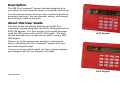
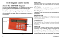
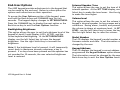
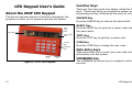
Fire Command™ Keypad
XR5
User’s Guide
Silencing an Alarm
While the fire alarm horns, strobes, or sirens are sounding use one of the following methods to silence the alarm depending
on which type of keypad you own.
690F LCD Display Keypad
While the alarm bell or siren is sounding, enter the user code. The keypad displays ALARM SILENCED.
692F LED Keypad
Press the SILENCE key and enter the user code to silence a system alarm and the keypad sounder.
Copyright © 2000-2002 Digital Monitoring Products, Inc.
Information furnished by DMP is believed to be accurate and reliable.
This information is subject to change without notice.
User's Guide
for XR5 Fire Command™ Panels
Table of Contents
Section
Page
Emergency Evacuation Plans .................................. iv
Description ........................................................ 1
About this User Guide ........................................... 1
About the 690F LCD Keypad .................................... 2
End-User Options .......................................... 3
Fire Command Messages ....................................... 4
Fire Command Tones ............................................ 5
Fire System Terms ............................................... 5
Silencing the Bells During an Alarm ............................ 5
Silencing the keypad trouble sounder ......................... 5
Keypad User Menu ............................................... 6
Sensor Reset ...................................................... 7
System Test ....................................................... 7
Fire Drill ........................................................... 8
User Codes ........................................................ 8
Display Events .................................................... 8
Zone Event Displays ....................................... 9
Zone Bypass Event Displays .............................. 9
Supervisory Event Displays ............................... 9
Auto Recall Event Displays ............................... 9
Section
Page
About the 692F LED Keypad ................................... 10
Function Keys ............................................. 10
Data Entry keys ........................................... 10
Command key ............................................. 10
System LEDs .............................................. 11
Zone Alarm and Trouble LEDs ........................... 11
Alert Tones ................................................ 11
Keyboard Backlighting ................................... 11
Keypad Function Keys ........................................... 12
Resetting Sensors ............................................... 13
Testing the System ............................................. 13
User Codes ....................................................... 13
2-Button Fire Keys .............................................. 13
iii
Emergency Evacuation Plans
First Floor
The National Fire Protection Association recommends that
you establish an emergency evacuation plan to safeguard
lives in the event of a fire or other emergency. Use the
following steps as a guide.
Fire Escape
Draw a floorplan of your home or business
On a sheet of paper, draw the walls, windows, doors, and
stairs. Also draw any obstacles a person may encounter
exiting the building.
Develop escape routes
Determine at least two routes the occupants in each room
can take to safely escape. One route can be the most
obvious such as the door. Another might be through a
window that can be easily opened.
Second Floor
Window Ladder
Building Front
Building Back
Draw arrows on the floorplan to show escape routes from
each room.
Decide where to meet
Prearrange a meeting place at a neighbor's house or across
the street in the front of the house. Always perform a head
count to make sure all occupants safely exited. NEVER
ENTER A BURNING BUILDING. If the head count shows a
person missing, give this information immediately to the
authorities. Never enter a burning building to look for
someone.
iv
Practice your escape plans
Devising an escape plan is only the beginning. For the plan
to be effective, everyone should practice the escape routes
from each room.
Description
The XR5 Fire Command™ system has been designed with
your safety in mind using the latest in computer technology.
You can perform system functions such as silencing bells by
pressing a few keys. You can also add, delete, and change
personal user codes at any time.
About this User Guide
This User Guide will discuss features of the XR5 Fire
Command™ system using both the 690F LCD keypad and the
692F LED keypad. The first section of the guide discusses
using the XR5 system with a 690F LCD keypad. The back
section describes how to operate the system using a 692F
LED keypad.
692F Keypad
Please turn to the appropriate section for information
about controlling your Fire Command™ system with your
particular keypad model.
If you are not sure which model you have, please compare
your keypad with the two images to the right.
690F Keypad
Introduction
1
LCD Keypad User’s Guide
About the 690F LCD Keypad
This device has been placed on the premises to allow you to
properly operate the system and review previous event
history. The keypad provides a passcode protected User
Menu where you can access the functions needed to
operate the system. See Keypad User Menu. In addition to
the User Menu, the items below list operational features of
your keypad.
POWER LED
Select Keys
Data Entry
Keys
Back
Arrow Key
COMMAND
Key
690F Fire Command Keypad
2
Select keys
These keys allow you to choose an option by pressing the
Select key under the choices shown in the display.
LCD display
The keypad uses a backlit LCD display and plain English text
to show events occurring on your system.
Data Entry keys
These keys allow you to enter the code number when using
the system.
Back Arrow key
The Back Arrow key allows you to back up through the list
of functions in the User Menu, or make corrections when
entering information.
COMMAND key
The COMMAND key allows you to advance through the
options on the keypad display, and enter information into
the system.
Power LED
This remains on steady as long as your fire system is
connected to its AC power supply. Should there be an
interruption, the green LED will turn off. The system’s
backup battery maintains normal operation for a time,
allowing you to contact our service department. Should the
battery power become low, the Power LED flashes.
LCD Keypad User’s Guide
End-User Options
The 690F keypad provides adjustments to the keypad that
can be made by the end-user. Below is a description the
options and instructions on their operation.
To access the User Options portion of the keypad, press
and hold the Back Arrow and COMMAND keys for two
seconds. The keypad display changes to SET BRIGHTNESS.
Press the COMMAND key to display the next option or the
Back Arrow key to exit the User Options function.
Backlighting Brightness
This option allows the user to set the brightness level of the
keypad’s Liquid Crystal Display (LCD), AC LED, and the
Green keyboard backlighting. At the SET BRIGHTNESS
display, use the left Select key to lower the keypad
brightness. Use the right Select key to increase the
brightness.
Note: If the brightness level is lowered, it will temporarily
revert back to maximum intensity whenever a key is
pressed. If no keys have been pressed and the speaker has
not sounded for 30 seconds, the user selected brightness
level is restored.
LCD Keypad User’s Guide
Internal Speaker Tone
This option allows the user to set the tone of the keypad’s
internal speaker. At the SET TONE display, use the top left
Select key to make the tone lower. Use the right Select key
to make the tone higher.
Volume level
This option allows the user to set the volume level of the
keypad’s internal speaker for key presses and prewarn
conditions. During alarm, trouble, and prewarn conditions,
the volume is always at maximum level. At SET VOLUME
LEVEL, use the left Select key to lower the keypad volume.
Use the right Select key to raise the volume.
Model Number
The LCD displays the keypad’s model number as well as the
firmware version and date. The information cannot be
changed by the user.
Keypad Address
The LCD displays the keypad’s current address as
programmed the Keypad Address option discussed below.
The information cannot be changed by the user. Press the
Back Arrow key to exit the User Options function.
3
Fire Command Messages
SYSTEM NORMAL
This display indicates that fire protection devices, phone
lines to the panel, and the panel itself, are in good
condition.
ALARM
A fire, supervisory, or auxiliary zone has been tripped.
Your system may sound the fire bells, strobes, and any
other response programmed into the system.
ALARM SILENCED
A user has silenced the fire bells by entering the code or
by using the Alarm Silence function in the User Menu. Even
though the bells are silenced, the system is still in a state
of alarm and, depending on the keypad model, the keypad
keys will glow red or a red LED on your keypad will flash
until a System Reset is performed (see page 2).
BYPASS
A zone has been disabled by the system due to repeated
trips. If the zone remains normal for one hour it can be
restored into the system.
4
ENTER CODE
The system requires you to enter the user code. As you
enter the code, the display shows an asterisk (*) in place of
each digit pressed.
TRY AGAIN
The user code you have entered is not recognized by the
system. Check the code and try again.
INVALID CODE
You receive this message if you enter an incorrect user code
a second time, after receiving the Try Again message.
PH LINE 1 TRBL
There is a problem with the phone line connected to your
system. Call for service as soon as possible.
TROUBLE
There is a problem with a protection device or system
component. This display is accompanied by a description of
the problem.
SERVICE REQUIRED or SYSTEM TROUBLE
There is a problem on the system. Call for service.
LCD Keypad User’s Guide
Fire Command Tones
Your keypad also contains a small speaker that alerts you to
events as they occur on your system. Below are brief
descriptions of the different tones you’ll hear from the
keypad:
Key press tone: A short beep when you press a key on the
keypad.
Status List
Status is a feature that automatically displays the status of
your system on the keypads. The Status List displays alarm
or trouble conditions on zones and trouble conditions that
occur with AC or battery power or the phone lines. If more
than one alarm or trouble condition occurs at the same
time, the keypad displays this information in order of
occurrence.
Trouble tone: A steady tone indicating a trouble condition
on your system. Press a Select key and then enter the user
code to silence the trouble tone.
Silencing the Bells During an Alarm
Fire Alarm Tone: Your keypad sounds a siren-like tone in
one-second intervals. This is in addition to other bells or
sirens you may have on your system.
Silencing the Keypad Trouble Sounder
Fire System Terms
Zone
A zone refers to one or more fire system devices. For
example, smoke detectors on the east side of the premises
can be grouped together under the zone name EAST
SMOKES.
While the alarm bell or siren is sounding, enter the user
code. The keypad displays ALARM SILENCED.
To silence the trouble sounder in the keypad, press any
Select key on the keypad. To silence the keypad sounder
when a Supervisory zone is in alarm, you must enter the
user code.
Central Station Monitoring
Your system can also be programmed to send alarm and
trouble reports to a central station where operators can
dispatch the appropriate authorities.
LCD Keypad User’s Guide
5
Keypad User Menu
Menu Option
Description
Many of the features of your system are accessible in the
User Menu you can access from the keypad. The menu
requires you to enter the user code before you can access
any functions.
SENSOR RESET
Resets smoke detectors that have
latched due to an alarm condition.
SYSTEM TEST
Tests the system’s siren,
communication to the central
station, and backup battery.
1. Press the COMMAND key until MENU? NO YES displays.
FIRE DRILL
2. Select YES. The keypad displays ENTER CODE: –. Enter the
user code and press the COMMAND key. You can now scroll
down through the list of system features.
Allows you to test the system’s
notification appliances, such as fire
bells and strobes.
USER CODES
Allows you to add, delete, or
change user codes and authority
levels.
DISPLAY EVENTS
Allows you to view or print the last
200 events that occurred on your
system.
To access the User Menu:
User Menu Options
The list below shows the User Menu options in the order
they will appear in the display. A detailed description of
each option follows in this guide.
The following pages detail each user menu item and
provide instructions on when and how to use them properly.
6
LCD Keypad User’s Guide
Sensor Reset
System Test
Function: Sensor Reset momentarily removes power to
smoke detectors allowing them to reset after they have
tripped. The detectors must be reset before they can
detect any additional alarm conditions.
Function: Tests the battery, alarm bell or siren, and
communication to a central station. The System Test
function begins automatically as soon as you select it.
Make sure all smoke is cleared from around the smoke
detectors before performing a Sensor Reset to prevent the
alarm from occurring again.
1. Access the User Menu. Press the COMMAND key until
SYSTEM TEST? displays.
2. Press any Select key. The system test begins automatically
and the keypad displays:
1. Access the User Menu.
1) BELL SOUNDING during a two second bell test, then:
2. When SENSOR RESET? displays, press any Select key. The
keypad displays SENSORS OFF for five seconds followed by
SENSORS ON.
2) BATTERY - OKAY or BATTERY - TRBL to indicate the
condition of the battery, then:
3. The keypad returns to the status display.
Enter the user code to reset sensors
You can also just enter the user code and press COMMAND
to reset the sensors without having to enter the User Menu.
3) * TRANSMIT TEST and ATTEMPT NO : 1 during the
transmit test, then:
4) * TRANSMIT OKAY or TRANSMIT FAILED to show the
results of the transmit test, then:
5) TEST END to indicate the System Test is complete.
6) You can cancel the transmit test by pressing the Back
Arrow key.
* The transmit tests are not applicable for local systems.
LCD Keypad User’s Guide
7
Fire Drill
Display Events
Function: Allows you to practice fire drill evacuations.
Function: Allows you to review up to 16 past events that
occurred on your system in the order of their occurrence.
1. Access the User Menu. Press COMMAND until FIRE DRILL
displays.
2. Press any Select key. The keypad displays SURE? NO YES.
Press the Select key under YES. The system rings the bells
until you enter the user code or until the programmed bell
time expires.
User Codes
Function: Allows you to change the user code number you
enter at the keypad.
NOTE: The user code must always have 4 digits.
Zone Events - Records zone alarms, troubles, restorals, and
service.
Supervisory - Records problems with the system’s hardware
components.
The system’s memory can hold up to 16 events. After 16
events are in memory, any new event causes the oldest
event to be cleared.
1. Access the User Menu.
1. Access the User Menu.
2. Press COMMAND until DISPLAY EVENTS? appears.
2. Press COMMAND until CODE NO: * * * * displays.
3. Press any Select key. The keypad displays the first recorded
event. Use COMMAND to scroll down through the event
displays.
3. Press any Select key. The keypad displays CODE NO: –.
Enter a new 4-digit user code. If the code you entered is a
special service code used internally by the system, the
keypad displays ALREADY IN USE. You must enter a
different user code.
8
The system records two event types:
Use the Back Arrow key to scroll back up through the event
displays. If you press the Back Arrow key when you first
enter Display Events, the keypad returns to the Status List.
LCD Keypad User’s Guide
Zone Event Displays
Supervisory Event Displays
# FIRE ALARM
POWER TROUBLE
The display actually contains three separate sections.
The display contains two separate sections.
# - Records the zone number. Press the Select key under the
zone number to display the custom zone name programmed
into the system.
POWER - The type of condition that occurred on your
system.
FIRE - This is the type of zone on which the activity
occurred. There are three possible zone types you may see
on your keypad.
PH LINE # - Problem with phone line 1 or 2.
FIRE - Fire
SUPV - Supervisory
AUX1 - Auxiliary 1
ALARM - This is the event that occurred. There are 3 event
types:
ALARM
TROUBLE
RESTORE
Zone Bypass Event Displays
# BYPAS
BYPAS - This zone has been bypassed by the system.
RESET - This zone has been reset by the system.
POWER - Problem with the AC power supply.
BATTERY - Problem with a low battery. This could be due to
the battery exceeding its life expectancy. Call the service
department whenever you see a low battery display.
The status regarding that condition.
TROUBLE
RESTORE
Auto Recall Event Displays
Your system sends periodic recall (test) reports to the
central station to test the communications link. Each
successful test transmission is logged into the Display
Events and shown as AUTO RECALL.
Press the Select key under the zone number to display the
custom zone name programmed into the system.
LCD Keypad User’s Guide
9
LED Keypad User’s Guide
About the 692F LED Keypad
This device has been placed at locations throughout the
premises to allow you to properly operate the system.
Zone
Alarm
LEDs
System LEDs
Zone Trouble
LEDs
Function
Keys
Data Entry
Keys
Function Keys
There are four keys under the display called the Function
keys. These keys allow you to perform system operations
by pressing one key, followed by the entry of a user code.
SILENCE Key
Press the SILENCE key to silence the alarm bells.
RESET Key
Press the RESET key to perform a sensor reset and silence
the alarm bells.
TEST Key
Press the TEST key to perform a system test.
CODE Key
Press the CODE key to change the user code.
Data Entry keys
These keys allow you to enter your user code and other
information into the system.
SPECIAL
Key
COMMAND
Key
Figure 2: 692F LED Keypad
10
COMMAND key
The COMMAND key allows you to complete a data entry
function.
LED Keypad User’s Guide
System LEDs
Zone Alarm and Trouble LEDs
The Fire Command Center incorporates three LEDs to indicate
the status of the system. The three indicator lights are
described below.
Red Zone Alarm LEDs
On steady during an alarm condition.
Yellow Silenced LED
On when the system is when the bells are silenced manually
from the keypad or after the Bell Cutoff time.
Off when a Sensor Reset is performed or if the alarm sounds
again.
Yellow Trouble LED
On when the system is unable to send a report to your
central station or when the phone line is in a bad condition.
Off when the system is operating correctly.
Pulse (1 second on, 1 second off) when there is a problem
with the system. Call for service.
Green Power LED
On when AC and battery power are okay.
Off when the zone has restored to normal and a Sensor
Reset has been performed.
Yellow Zone Trouble LEDs
On during a trouble condition.
Off when the zone restores to normal.
Pulses if the zone alarm or trouble is a Supervisory type
zone.
Alert Tones
Steady Tone indicates a trouble condition on the system or
a fire zone. Follows the operation of the bells. Pressing any
key silences a steady alert tone.
1 Short Beep is emitted each time a key is pressed or a
valid function is entered.
Off during AC trouble.
4 Short Beeps are emitted when an incorrect key or
function is entered.
Flash (1/2 second on, 1/2 second off) when the system’s
battery is low or missing.
Keyboard Backlighting
LED Keypad User’s Guide
The keyboard on the 692F lights any time a key is pressed
or the alert buzzer sounds making it easy for a user in a
darkened room to enter their code or perform a command
function.
11
Keypad Function Keys
SILENCE
Press the SILENCE key and enter the user code to silence a
system alarm and the keypad sounder. You may also use
the SILENCE key to silence the bells during the Fire Drill
function.
RESET
Press the RESET key and enter the user code to reset a
zone after an alarm.
This resets all zone alarm LEDs and momentarily drops
power to the panel’s zones 2 to 5 and smoke power output.
TEST
Press the TEST function key and enter the user code to
initiate the panel’s System Test function.
This test rings the panel bells for 2 seconds, checks the
battery charge level, and sends a system test report to the
central station on monitored systems.
12
CODE
To change the system user code, press CODE, enter the
current user code followed by 0 + 1, and then enter the
new 4-digit user code.
The user code must always be 4 digits.
SPECIAL
Pressing the SPECIAL key and entering the user code
initiates the Fire Drill function.
The Fire Drill sounds the alarm bells and keypad sounder for
the duration of the Bell Cutoff time. If the Bell Cutoff time
is set to zero (0), the Fire Drill continues until the bells are
silenced by entering a code. No keypad LEDs are turned on
and no reports are sent to the central station during the
Fire Drill.
In the event of a real fire during a fire drill, the system
sends a report to the central station and the LED for any
fire-detecting zone glows red on the 692F.
Manual Fire Alarm
To manually initiate a Fire Alarm, press and hold the TEST
and CODE keys simultaneously for about 2 seconds until the
alarm sounds.
LED Keypad User’s Guide
Resetting Sensors
User Codes
Use this function to reset smoke detectors after an alarm
when the Fire zone light is flashing in alarm memory.
Use this function to change the current User Code.
Enter COMMAND + 4 + 7 to perform a Sensor Reset. The
system resets the smoke detectors and stops the flashing
light if the zone restores to normal.
You can also initiate a Sensor Reset by pressing the RESET
function key followed by your User Code.
Testing the System
It is good practice to test your system at least once each
week. This assures you that the system is working correctly
and identifies any potential problems.
Enter COMMAND + 4 + 1 to perform a system test. The bell
rings for 2 seconds then the battery and communications to
the central station are tested.
Press the CODE key followed by the current User Code. You
will hear one beep if successful. Enter 0 (zero) + 1. Enter
the new 4-digit User Code.
2-Button Fire Keys
If your system has a label showing a Flame under the TEST
and CODE keys, the optional Panic key function has been
enabled.
Press the two keys over the icon, and hold them down for
at least 2 seconds. The system will send a Fire report to
the central station. The keypad beeps to confirm the Fire
key entry.
You can also initiate a System Test by pressing the TEST
function key followed by your User Code.
LED Keypad User’s Guide
13
Index
Symbols
F
S
2-Button Fire Keys (LED) 13
690F LCD Keypad 2
692F LED Keypad 10
Fire Command Messages (LCD) 4
Fire Command Tones (LCD) 5
Fire Drill (LCD) 8
Fire System Terms (LCD) 5
Sensor Reset 7
Sensor Reset (LCD) 6
SILENCE (LED) 10
Silencing the Bells During an Alarm
(LCD) 5
Silencing the Keypad Trouble Sounder
(LCD) 5
System LEDs (LED) 11
System Test (LCD) 7
A
Alert Tones (LED) 11
K
C
Keypad Function Keys (LED) 12
Keypad User Menu (LCD) 6
CODE Key (LED) 10
D
L
Display Events (LCD) 6, 8
LCD Keypad 2
LED Keypad 10
E
M
TEST (LED) 10
Testing the System (LED) 13
Manual Fire Alarm (LED) 12
U
R
User Codes (LCD) 6, 8
User Codes (LED) 13
User Menu (LCD) 6
End-User Options (LCD) 3
Event Displays
Supervisory 9
Zone 9
Zone Bypass 9
Event Displays (LED
Auto Recall 9
14
RESET (LED) 10
Resetting Sensors (LED) 13
T
Z
Zone Alarm and Trouble LEDs (LED) 11
Index
This page has been intentionally left blank.
LT-0296 (4/02)


![Lvn De Novo Board Game User Manual [VER 1.0]](http://vs1.manualzilla.com/store/data/005785305_1-ef88b505e9e90be8a5d323ed52b38254-150x150.png)