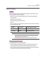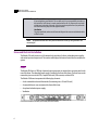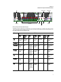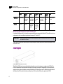
1
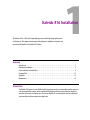
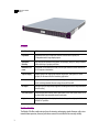
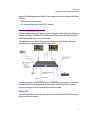
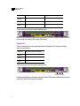
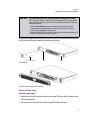
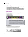
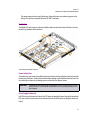
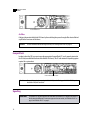
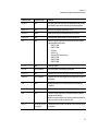
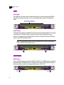
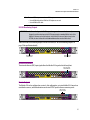
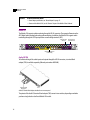
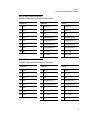
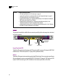
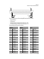
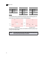
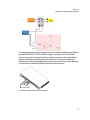
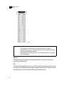
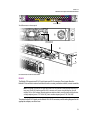
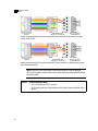
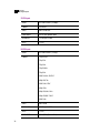
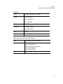
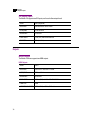
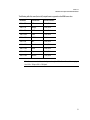
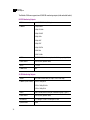
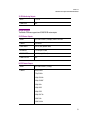
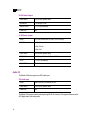
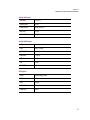
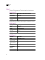
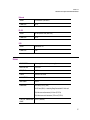
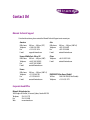
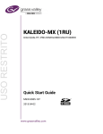
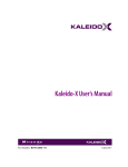
Kaleido-X16
Hardware Description & Installation Manual
Part Number: M869-9902-107
27 May 2011
0
Copyright © 2009–2011, Miranda Technologies Inc.
All rights reserved.
ATTENTION: please read the following terms and conditions carefully. By using Kaleido-X16
documentation, you agree to the following terms and conditions:
Miranda Technologies Inc. hereby grants permission and license to owners of Kaleido-X16 to use
their product manuals for their own internal business use. Manuals for Miranda Technologies Inc.
products may not be reproduced or transmitted in any form or by any means, electronic or
mechanical, including photocopying and recording, for any purpose unless specifically authorized
in writing by Miranda Technologies Inc.
A Miranda Technologies Inc. manual may have been revised to reflect changes made to the
product during its manufacturing life. Thus, different versions of a manual may exist for any given
product. Care should be taken to ensure that one obtains the proper manual version for a specific
product serial number.
Information in this document is subject to change without notice and does not represent a
commitment on the part of Miranda Technologies Inc.
ii
Title
Kaleido-X16 Hardware Description & Installation Manual
Part Number
M869-9902-107
Revision
27 May 2011, 7:30 pm
Kaleido-X16
Hardware Description & Installation Manual
Safety Compliance
This equipment complies with the requirements of the following standards for safety of
information technology equipment:
• CSA-C22.2 No. 60950-1-07
• UL 60950-1 (2nd Edition)
• EN 60950-1:2006 ITE
• IEC 60950-1:2005 (2nd Edition)
WARNING:
An appropriately listed/certified mains supply power cord must be used for the
connection of the equipment to the mains voltage at either 120V~ or 240V~.
CAUTION:
These servicing instructions are for use by qualified service personnel only.
To reduce the risk of electric shock, do not perform any servicing other than that contained
in the operating instructions unless you are qualified to do so. Refer all servicing to
qualified service personnel. Servicing should be done in a static-free environment.
Electromagnetic Compatibility
This equipment has been tested for verification of compliance with FCC Part 15, Subpart B
requirements for class A digital devices.
Note: This equipment has been tested and found to comply with the limits for a Class A digital device,
pursuant to Part 15 of the FCC rules. These limits are designed to provide reasonable protection against
harmful interference when the equipment is operated in a commercial environment. This equipment
generates, uses, and can radiate radio frequency energy, and, if not installed and used in accordance with
the instruction manual, may cause harmful interference to radio communications. Operation of this
equipment in a residential area is likely to cause harmful interference in which case the user will be
required to correct the interference at his own expense.
This equipment has been tested and complies with the requirements of the directive
2004/108/CE:
• EN 55022 Class A Radiated and conducted emissions
• EN 61000-3-2 Limits for harmonic current emissions
• EN 61000-3-3 Limitation of voltage changes, voltage fluctuations and flicker
• EN 61000-4-2 Electrostatic discharge immunity
iii
• EN 61000-4-3 Radiated, radio-frequency, electromagnetic field immunity
• EN 61000-4-5 Surge transient immunity
• EN 61000-4-6 Conducted disturbances immunity
• EN 61000-4-11 Voltage dips, short interruptions and voltage variations immunity
Warranty Policies
Warranty information is available in the Support section of the Miranda Web site (www.miranda.com).
Table of Contents
1 Kaleido-X16 Installation
1
Introduction . . . . . . . . . . . . . . . . . . . . . . . . . . . . . . . . . . . . . . . . . . . . . . . . . . . . . . . . . . . . . . . . . . . . . . . . . . . . . . . . . . . . . . . . . . . . . . . . . . . 1
Mechanical Installation . . . . . . . . . . . . . . . . . . . . . . . . . . . . . . . . . . . . . . . . . . . . . . . . . . . . . . . . . . . . . . . . . . . . . . . . . . . . . . . . . . . . . . . . . . 5
Frame and Electrical Installation . . . . . . . . . . . . . . . . . . . . . . . . . . . . . . . . . . . . . . . . . . . . . . . . . . . . . . . . . . . . . . . . . . . . . . . . . . . . . . . . . . 6
CompactFlash . . . . . . . . . . . . . . . . . . . . . . . . . . . . . . . . . . . . . . . . . . . . . . . . . . . . . . . . . . . . . . . . . . . . . . . . . . . . . . . . . . . . . . . . . . . . . . . . . 12
Signalling . . . . . . . . . . . . . . . . . . . . . . . . . . . . . . . . . . . . . . . . . . . . . . . . . . . . . . . . . . . . . . . . . . . . . . . . . . . . . . . . . . . . . . . . . . . . . . . . . . . . 12
Maintenance . . . . . . . . . . . . . . . . . . . . . . . . . . . . . . . . . . . . . . . . . . . . . . . . . . . . . . . . . . . . . . . . . . . . . . . . . . . . . . . . . . . . . . . . . . . . . . . . . . 25
2 Specifications
27
Inputs . . . . . . . . . . . . . . . . . . . . . . . . . . . . . . . . . . . . . . . . . . . . . . . . . . . . . . . . . . . . . . . . . . . . . . . . . . . . . . . . . . . . . . . . . . . . . . . . . . . . . . . 27
Outputs . . . . . . . . . . . . . . . . . . . . . . . . . . . . . . . . . . . . . . . . . . . . . . . . . . . . . . . . . . . . . . . . . . . . . . . . . . . . . . . . . . . . . . . . . . . . . . . . . . . . . . 30
Audio I/O . . . . . . . . . . . . . . . . . . . . . . . . . . . . . . . . . . . . . . . . . . . . . . . . . . . . . . . . . . . . . . . . . . . . . . . . . . . . . . . . . . . . . . . . . . . . . . . . . . . . . 34
Control . . . . . . . . . . . . . . . . . . . . . . . . . . . . . . . . . . . . . . . . . . . . . . . . . . . . . . . . . . . . . . . . . . . . . . . . . . . . . . . . . . . . . . . . . . . . . . . . . . . . . . . 36
Frame . . . . . . . . . . . . . . . . . . . . . . . . . . . . . . . . . . . . . . . . . . . . . . . . . . . . . . . . . . . . . . . . . . . . . . . . . . . . . . . . . . . . . . . . . . . . . . . . . . . . . . . 37
Contact Us!
39
v
toc
vi
Kaleido-X16 Installation
The Kaleido-X16 is a 1RU, multi-image display processor with high image quality and a
rich feature set. This chapter contains physical descriptions, installation instructions and
connection information for the Kaleido-X16 frame.
Summary
Introduction . . . . . . . . . . . . . . . . . . . . . . . . . . . . . . . . . . . . . . . . . . . . . . . . . . . . . . . . . . . . . . . . . . . . . . . . . . 1
Mechanical Installation . . . . . . . . . . . . . . . . . . . . . . . . . . . . . . . . . . . . . . . . . . . . . . . . . . . . . . . . . . . . . . . . . 5
Frame and Electrical Installation . . . . . . . . . . . . . . . . . . . . . . . . . . . . . . . . . . . . . . . . . . . . . . . . . . . . . . . . . 6
CompactFlash . . . . . . . . . . . . . . . . . . . . . . . . . . . . . . . . . . . . . . . . . . . . . . . . . . . . . . . . . . . . . . . . . . . . . . . . 12
Signalling . . . . . . . . . . . . . . . . . . . . . . . . . . . . . . . . . . . . . . . . . . . . . . . . . . . . . . . . . . . . . . . . . . . . . . . . . . . 12
Maintenance . . . . . . . . . . . . . . . . . . . . . . . . . . . . . . . . . . . . . . . . . . . . . . . . . . . . . . . . . . . . . . . . . . . . . . . . . 25
Introduction
The Kaleido-X16 system is a cost-effective multi-image processor. It can accommodate smaller systems or
scale up to production systems, where smaller building blocks with fewer input counts per display are
desirable. Each chassis can display up to 16 auto-sensing HD, SD, or Analog inputs that can be displayed
across two high resolution outputs at multiple sizes.
1 Kaleido-X16 Installation
Features
Features
Small form factor
1RU
Expandable
Expandable multi-room architecture, based on a chassis with 16 inputs, and
2 independent multi-image display outputs
Unmatched
flexibility
Any source can be repeated to any position, to any display, at any size, at any resolution,
without blocking or grouping restrictions
Kaleido-X16 as a
router
The Kaleido-X16 can behave as a router, with 16 input channels as sources and the two
RT OUT outputs as destinations
Superior display
Highest quality multi-image output without compression, with superior on-screen
graphics, for the most critical live monitoring applications
128 audio channels
Unprecedented audio performance with the ability to monitor up to 128 channels of
audio, including embedded, discrete analog, discrete AES from ABT
DVI inputs
DVI inputs (one per output head) mappable in the background of each output without the
need for scaling
Two-room layouts
Intuitive layout editor software allows rapid creation of two-room layouts, which can be
recalled quickly from networked remote control panels
Highly robust
Highly robust design, with multiple points of redundancy, and no single point of failure for
reliable 24/7 operation
Port Availability
The Kaleido-X16 offers a wide variety of ports for incoming and outgoing signals. However, with a view
towards future expansion, there are ports whose connections exist but that are currently not fully
2
Kaleido-X16
Hardware Description & Installation Manual
supported. The following ports on the Kaleido-X16 are not supported in the current release of the KaleidoX Software:
• OPTION streaming output connector
• PC In analog audio input ports at the AUDIO I/O connector
Overview of the Kaleido-X16 System
The following diagram shows a basic Kaleido-X16 system configuration, with a single Kaleido-X16 feeding
2 monitor wall displays. The Kaleido-RCP2 would be located on the production desk, while the Client PC
could be anywhere with Internet access to the network.
The diagram below shows a Kaleido-X16 system with its inputs and outputs. Examples of the various
external devices that connect to the Kaleido-X16 are also shown.
The Kaleido-X16 system is available in two model types: a single-head model (Kaleido-X16-S) and a dualhead model (Kaleido-X16-D). Throughout this manual, Kaleido-X16 refers to both models unless it is
necessary to distinguish the single-head model from the dual-head model.
Kaleido-X16-D
There are two heads (Head 1 and Head 2) on the dual-head Kaleido-X16 (Kaleido-X16-D). The Input and
Output connections are as follows.
3
1 Kaleido-X16 Installation
Kaleido-X16-S
Connector
Number of connectors on Head 1
Number of connectors on Head 2
MV OUT
1
1
SDI OUT
1
1
DVI IN
1
1
The rear connector panel for this model is displayed, below:
In addition to the difference in the number of output heads, the Audio I/O TBA pinout is different between
the two models (see “Audio I/O TBA” on page 16 for details).
Kaleido-X16-S
There is one head (Head 1) on the single-head Kaleido-X16 (Kaleido-X16-S). The Input and Output
connections are as follows.
Connector
Number of connectors on Head 1
MV OUT
1
SDI OUT
1
DVI IN
1
The rear connector panel for this model is displayed, below:
No Head 2 connectors
(DVI IN2, SDI OUT2, MV OUT2)
In addition to the difference in the number of heads, the Audio I/O TBA pinout is different between the two
models (see “Audio I/O TBA” on page 16 for details).
4
Kaleido-X16
Hardware Description & Installation Manual
Mechanical Installation
Unpacking
Make sure the following items have been shipped with your Kaleido-X16. If any of these are missing,
contact your distributor or Miranda Technologies Inc.
• Kaleido-X16 unit with one or two power supplies pre-installed (second power supply optional)
• Two support brackets
• One AC power cord per power supply
• DVD including manuals, software and release notes
• One mouse
• Four serial port adapters (one with straight wiring and one with crossover wiring for each of the two
RS-422 ports on your multi-viewer):
Part number
Adapter cabling
RS-422 pinout at the DE-9P connector
1737-3000-102
Straight
Controller (SMPTE master) mode
1792-3700-100
Crossover
Tributary (SMPTE slave) mode
Notes
• The Kaleido-RCP2 unit is optional and is not included in the standard Kaleido-X16 package.
Refer to the Kaleido-RCP2 Guide to Installation and Operation (available on the DVD that
shipped with your system) for more information.
• The standard Kaleido-X16 comes with one PSU. A redundant, second PSU is optional.
Mounting the Kaleido-X16 in a Rack
To mount the Kaleido-X16 in a standard 19-inch rack:
1. Install both support brackets at the back of the rack by using suitable screws and washers (not
included), so that the bottom of the Kaleido-X16 frame will be supported by the brackets.
2. Insert the Kaleido-X16 frame at the designated location within the rack, and secure the front of the
frame to the rack by using suitable screws and washers (not included).
5
1 Kaleido-X16 Installation
Frame and Electrical Installation
IMPORTANT:
Mobile Installation
If you are deploying your Kaleido-X16 in a mobile unit, it is your responsibility to make sure
the back of the multi-viewer is securely attached to the rack. For instance you may install
a blank panel at the back of the rack, so that it meets the top of the frame, to prevent the
frame from bouncing away from the support brackets.
Ventilation
For proper ventilation, make sure the front and side panel air vents are not blocked and the
air filter is clean.
Note: The optional Kaleido-RCP2 may also be installed in a rack, by using the KRCP-RK2
mounting kit.
Frame and Electrical Installation
The Kaleido-X16 multi-viewer is a self-contained unit consisting of a frame, redundant power supplies,
and various input and output cards. The monitor wall displays and external control devices complete the
system.
Frame
The Kaleido-X16 frame is 1 RU high. Input and output connectors are mounted on a connector panel on the
rear of the frame. The redundant power supply is installed in the front of the frame. The front cover can be
removed to give access to the PSUs, CompactFlash card, USB connector, and basic LEDs.
The Kaleido-X16 frame incorporates the following key elements:
• A rack-mountable mechanical framework (for mounting into a 19-inch EIA rack)
• A removable door to cover and protect the front of the frame
• An optional redundant power supply
• Ventilation
Front view of the Kaleido-X16 frame (PSUs installed; front cover removed)
6
Kaleido-X16
Hardware Description & Installation Manual
CPU
General Status
SDTI
Severity
DVI Inputs
Video Inputs
CPF Activity
Reference Input
LTC
LEDs on the front of the frame (behind the cover)
The LEDs on the front of the frame (behind the cover) indicate the following conditions depending on their
color and whether they are blinking or not:
LED
LED Status
Green
Blinking
green
Red
Blinking
red
Yellow
Blinking
yellow
Off
CPU
Normal op- Application
eration
booting
Error
Live Update
OS Booting
N/A
Front cover is
closed
CPF Activity
N/A
Activity
N/A
N/A
N/A
N/A
No Activity
Video Inputs
Inputs are
locked
N/A
Inputs are
unlocked, or
no input
ERROR ON
SIGNAL
N/A
N/A
Front cover is
closed
DVI Inputs
Inputs are
locked
N/A
Inputs are
unlocked, or
no input
ERROR ON
SIGNAL
N/A
N/A
Front cover is
closed
LTC
LTC valid
N/A
No signal
N/A
N/A
N/A
Front cover is
closed
Ref. Input
Input is
locked
N/A
Input is unlocked, or no
input
ERROR ON
SIGNAL
N/A
N/A
Front cover is
closed
SDTI
Inputs are
locked
N/A
Inputs are
unlocked, or
no input, or
no SDTI signal
ERROR ON
SIGNAL
N/A
N/A
Front cover is
closed
7
1 Kaleido-X16 Installation
Monitoring the Temperature of the Kaleido-X16
LED
LED Status
Green
Blinking
green
Gen. Status
System OK
Severity
Boot OK
Red
Blinking
red
Yellow
Intrusive self- Configuration Failed,
diagnostic
Safe Mode
finished
Firmware
Upgrading
Boot up Diag- Firmware
error
nostic (Verbose switch
on)
Booting
N/A
Fatal error, CALL
TECH SUPPORT
Boot error,
Need liveupdate
Blinking
yellow
N/A
Off
Front cover is
closed
No power
Monitoring the Temperature of the Kaleido-X16
For optimal performance, it is strongly recommended that you operate the Kaleido-X16 multi-viewer in an
environment with an ambient temperature between 0 °C and 40 °C.
IMPORTANT:
When measuring the ambient room temperature, take your readings from directly in front of
the Kaleido-X16 frame.
There are two factors that could influence airflow inside the frame: altitude and airflow obstruction on the
sides of the unit.
Power Supplies
Power supply for the Kaleido-X16 frame
The Kaleido-X16 frame is powered by dual redundant, current-sharing power supply units (PSUs). The
PSUs are installed and removed from the front of the frame and are hot-swappable, so that a defective
supply may be replaced without removing the Kaleido-X16 frame from service. When facing the front of
the frame, the PSU on the left side is referred to as PSU A and the PSU on the right side is PSU B.
8
Kaleido-X16
Hardware Description & Installation Manual
IMPORTANT:
If your frame has only one PSU, it must be installed in Slot A (left side of frame)
There are two power supplies: an operational PSU and a redundant PSU. The system operates
with a single PSU. If you choose to have only one PSU installed in your Kaleido-X16 frame, you
should do the following:
• Clear the PSU B Installed check box for this Kaleido-X16 frame in XAdmin (see the
“Configuring Power Supply Redundancy on the Kaleido-X16” section in the “Getting
Started” chapter of the Kaleido-X User’s Manual).
• Install the single PSU (PSU A) in Slot A (the left side of the frame when facing the front of the
frame) (see “Installing a Power Supply” on page 10).
Access the power supplies by removing the front cover of the frame. Viewed from the front of the frame,
the PSUs are located on the left-hand and right-hand sides of the frame:
PSU A removed from Slot A
Slot A
Slot B
PSU slot locations
Two PSUs installed in a frame; front cover removed
Removing a Power Supply
To remove a power supply:
1. Open the front cover of the frame and locate the power supply (PSU) you would like to remove (either
the left or the right side).
2. Pull on the handle on the right side of the PSU and pull the PSU out of the frame.
9
1 Kaleido-X16 Installation
Installing a Power Supply
Installing a Power Supply
To install a power supply:
1. Position the power supply (PSU) in front of an empty power supply slot in front of the frame, with the
connector end towards the frame and the PSU handle on the right side.
2. Slide the PSU into the empty slot, moving it gently until it contacts the sockets at the rear of the slot.
3. Push firmly but gently on the PSU faceplate until the PSU’s connectors have mated with the frame's
sockets, and the PSU will go in no further.
Powering up the Kaleido-X16
Separate AC power sockets serve the two power supplies. On the rear of the frame, connect both power
sockets of the Kaleido-X16 to an appropriate power source using the supplied power cords.
As seen from the rear of the frame:
• The left power socket is for PSU B.
• The right power socket is for PSU A.
Power socket for PSU B
IMPORTANT:
Power socket for PSU A
• A Kaleido-X16 multi-viewer can draw 4.0 amps of current. Ensure that the circuit to which
the frame is connected can handle that load, and that of any other connected devices.
• If you only have one PSU, make sure you plug your power cable into the power connector on
the right side of the rear connector panel (as you face the rear of the frame). This should be
on the same side of the frame as the one PSU you have installed. If you do not do this, your
system cannot draw power.
• If you have two PSUs, make sure you plug in both power cables into both power connectors
of the rear connector panel. If you do not do this your system cannot have PSU redundancy.
To power up the Kaleido-X16:
1. Plug the power cord(s) from the Kaleido-X16 into a grounded power outlet.
2. Push the power button at the front of the frame (behind the front cover).
Power button
10
Kaleido-X16
Hardware Description & Installation Manual
The startup sequence takes a couple of minutes, during which time some video may appear on the
displays. The startup is completed when the CPU LED is solid green.
Ventilation
The Kaleido-X16 multi-viewer is cooled by ventilation intakes located on the front of the frame. Fans are
located in key positions within the frame:
Air flow through the Kaleido-X16 frame
Frame Cooling Fans
Air intake for the multi-viewer is handled by six fans located near the front of the frame and two heat sinks
near the rear of the frame. The fans draw air into the frame through a grille and filter in the front cover. The
heat sinks help to exhaust air out through grates on either side (see diagram, above).
IMPORTANT:
The Kaleido-X16 multi-viewer requires a constant flow of cooling air during operation. DO NOT
OPERATE THE UNIT IF THESE FANS ARE NOT WORKING. If a fan is not working contact your next
level of support.
Power Supply Cooling Fan
Each PSU has one fan located on its front. Each PSU draws air through the frame’s front grille, through the
PSU, then out to the closest rear fan to be exhausted out the side of the frame (see diagrams, above and
below):
11
1 Kaleido-X16 Installation
Air Filter
PSU fan on front of PSU A
Air Filter
Cooling air drawn into the Kaleido-X16 frame by the ventilating fans passes through a filter located behind
a grille in the front cover of the frame.
See also:
For more information about cleaning the air filter, see “Cleaning the Air Filter” on page 25.
CompactFlash
In order to boot the CPU, you must ensure the appropriate CompactFlash (CF) card is properly inserted in
the CF slot (accessible from the front of the Kaleido-X16 frame). The CF card contains the operating system
required for a system boot.
CF slot on front of Kaleido-X16 frame
See also:
For more information about starting the Kaleido-X16, see the “Setting up the Kaleido-X16” chapter in
the Kaleido-X16 Quick Start Guide.
Signalling
IMPORTANT:
12
The Kaleido-X16-D model supports two Heads while the Kaleido-X16-S supports one Head. For
details about the difference in connector support on the two models, see “Kaleido-X16-D” on
page 3 and “Kaleido-X16-S” on page 4.
Kaleido-X16
Hardware Description & Installation Manual
Connector label
Connector type
Function
DVI IN1-2
DVI
DVI input signal that can be used as a background in the monitor
wall display in place of the internally-generated background.
INPUTS 1-16
BNC
HD/SD-SDI or composite video inputs 1 to 16.
MV OUT 1-2
HDMI
HDMI output including embedded audio for each head.
SDI OUT 1-2
BNC
Serial digital HD output signal for monitoring purposes.
REF
BNC
Reference signal to genlock the multi-viewer to the local plant.
Supported Reference formats:
•SMPTE 170M
•SMPTE 318M
•ITU 624-4
•BUT 470-6
•PAL and NTSC composite sync
•SMPTE 274M
•SMPTE 296M
•SMPTE 240M
LTC 1-2
BNC
Time code inputs.
GPI 1-44
DB-44 (female)
GPI input/output (unidirectional) connections.
RT OUT 1-2
BNC
Supports 3Gbps-SDI, HD-SDI, and SD-SDI router output signals.
AUDIO I/O
HD-26 (female)
Supports two AES3 audio outputs or two analog audio inputs for
monitoring.
SDTI
BNC
Multiplexed audio from an external audio box (Audio Bridge
Terminal).
ETHERNET
RJ-45
100 Base-T Ethernet connection.
USB
USB
Connect a mouse, keyboard, or USB flash memory for software
upgrade or data backup.
Note: There are three USB ports, one on the front of the frame (behind the
front cover) and two on the rear connector panel.
RS-422
RJ-45 (see “RS-422”
on page 23)
Connect to an RS-422 (SMPTE 207M, EBU-3245) or RS-485 device
or network.
13
1 Kaleido-X16 Installation
Inputs
Inputs
Video Signals
The 16 BNC Input connectors located on the Kaleido-X16 frame’s rear connector panel support HD/SD/
3 Gbps SDI or composite video inputs 1 to 16 (see “Video Signal Inputs” on page 27 for specification
details).
BNC connectors (16) for SD-SDI, HD-SDI,
3Gbps-SDI, and Analog Composite Inputs
Graphic Signals
The Kaleido-X16-D supports two digital DVI inputs, one for each of two heads (the Kaleido-X16-S supports
a single DVI input). The DVI IN connectors on the rear panel are female, dual-link DVI-I universal
connectors. The supported signal and cabling for this connection is single-link DVI-D (see “DVI Graphic
Inputs” on page 30 for specification details).
Note: The two DVI inputs cannot be crossed nor combined. That is, DVI IN 1 must output on
Head 1, and DVI IN 2 must output on Head 2.
DVI-D In1
DVI-D In2
Mosaic Outputs
HDMI Outputs
There is one HDMI output for each output head (MV OUT 1, MV OUT 2). See “HDMI Outputs” on page 30 for
specification details. The HDMI connection is a high definition connection for the multi-viewer output,
which carries audio and video, and can support resolutions up to 1920 × 1200.
MV OUT 1/DVI OUT 1
14
MV OUT 2/DVI OUT 2
Kaleido-X16
Hardware Description & Installation Manual
Note: To use an HDMI output connection as a DVI output:
• Use an HDMI cable with an HDMI-to-DVI adapter at one end.
• Use an HDMI-to-DVI cable.
HD-SDI Monitoring Outputs
IMPORTANT:
Audio monitoring at the HD-SDI outputs is supported on recent hardware only.
Support for audio monitoring at the HD-SDI outputs requires version 5.30 (or later) of the
Kaleido-X Software, and recent hardware. In the XAdmin Status and Options page, under
SYSTEM, the value indicated for the Card revision attribute must be 0x4 or more.
There are two HD-SDI monitoring outputs: one for each head (see “HD-SDI Monitoring Outputs” on
page 32 for specification details).
BNC connector for
Mosaic SDI OUT 1
BNC connector for
Mosaic SDI OUT 2
External Reference
The external reference (REF) input signal allows the Kaleido-X16 to genlock to the local plant.
BNC connector for
External Reference
Router Outputs
The Kaleido-X16 can be configured as a router. In this configuration, up to two Kaleido-X16 channels are
considered as sources, and the destinations are the two RT OUT ports on the rear connector panel:
BNC connectors
for router outputs
15
1 Kaleido-X16 Installation
Audio I/O
See also:
For more information about:
• Router Output specifications, see “Router Outputs” on page 33.
• Routers and the Kaleido-X16, see the “Routers” chapter of the Kaleido-X User’s Manual.
Audio I/O
The Kaleido-X16 supports audio monitoring through its HD-26 connector. The supported formats are the
AES3 digital audio standard and analog audio monitoring. In addition, the Kaleido-X16 supports audio
monitoring through the SDTI input port from an audio bridge terminal (ABT).
BNC connector for
SDTI input
BNC connector for
External Reference
HD-26 audio I/O connector
for AES, Analog
Audio I/O TBA
To facilitate cabling of the audio inputs and outputs through the HD-26 connector, a terminal block
adapter (TBA) is available separately (Miranda part number NSH26M).
Audio I/O Terminal
Block Adapter
Audio I/O Terminal Block Adapter installed in rear connector panel
The pinout of the Audio I/O terminal block adapter (TBA) comes in two varieties, depending on whether
you have a single-head or dual-head Kaleido-X16 model.
16
Kaleido-X16
Hardware Description & Installation Manual
Audio I/O TBA Pinout on the Kaleido-X16-D
The Audio I/O TBA pinout on the Kaleido-X16-D is as follows:
Bottom row
Center row
Top row
19
GND
10
AES Out 1 (+)
1
AES Out 1 (-)
20
GND
11
AES Out 2 (+)
2
AES Out 2 (-)
21
GND
12
GND
3
GND
22
GND
13
Analog Left Out 1 (+)
4
Analog Left Out 1 (-)
23
GND
14
Analog Right Out 1 (+)
5
Analog Right Out 1 (-)
24
GND
15
Analog Left Out 2 (+)
6
Analog Left Out 2 (-)
25
GND
16
Analog Right Out 2 (+)
7
Analog Right Out 2 (-)
26
GND
17
PC In 1 Left
8
PC In 1 Right
18
PC In 2 Left
9
PC In 2 Right
Audio I/O TBA Pinout on the Kaleido-X16-S
The Audio I/O TBA pinout on the Kaleido-X16-S is as follows:
Bottom row
Center row
Top row
19
GND
10
AES 1 (+)
1
AES 1 (-)
20
GND
11
NC
2
NC
21
GND
12
GND
3
GND
22
GND
13
Analog Left Out 1 (+)
4
Analog Left Out 1 (-)
23
GND
14
Analog Right Out 1 (+)
5
Analog Right Out 1 (-)
24
GND
15
NC
6
NC
25
GND
16
NC
7
NC
26
GND
17
PC In 1 Left
8
PC In 1 Right
18
NC
9
NC
17
1 Kaleido-X16 Installation
Control
See also:
For more information about:
• SDTI audio specifications, see “SDTI Audio Input” on page 34.
• analog audio specifications, see “Analog Audio Input” and “Analog Audio Output” on page 35.
• AES output specifications, see “AES Outputs” on page 35.
• triggering audio monitoring, see “Triggering Audio Monitoring” in the “Operation of the Monitor
Wall” chapter of the Kaleido-X User’s Manual.
• calibrating audio monitoring delay, see “Calibrating the Audio Monitoring Delay” in the
“Calibrating the Kaleido-X” chapter of the Kaleido-X User’s Manual.
• calibrating audio monitoring color, see “Calibrating the Audio Monitoring Color” in the “Calibrating
the Kaleido-X” chapter of the Kaleido-X User’s Manual.
Control
The connectors located in the middle of the rear connector panel (the yellow and orange color-coded area)
are Control connectors.
BNC connectors
for LTC inputs
RJ-45 Ethernet
connector
DB-44 connector
for GPI I/O
RJ-45 connectors (2)
for RS-422 serial
connections
USB connectors (2)
Linear Time Code (LTC)
The Kaleido-X16 supports two linear time code (LTC) inputs over BNC connectors. The format is SMPTE 12M
unbalanced (see “Time Code Inputs (LTC)” on page 36 for specification details).
GPI I/O
The Kaleido-X16 supports status monitoring, genlock and GPI interfacing. The rear connector panel houses
all input and output connectors associated with GPI I/O. The Kaleido-X16 supports 32 GPI inputs and 4 GPI
outputs. The GPI connector type is a DB-44 (female on the connector panel; male on the cable):
18
Kaleido-X16
Hardware Description & Installation Manual
Pin 15
Pin 1
Pin 31
Pin 44
Pin 16
Pin 30
There are 44 GPI connector pins (40 not including GND) whose functions are as follows:
• 4 Ground (GND) pins
• 32 GPI Input pins
• 4 GPI Output Emitter pins (designated in the table, below, as “N”)
• 4 GPI Output Collector pins (designated in the table, below, as “P”)
The exact pinout for the GPI connector is as follows:
Bottom row
Middle row
Top row
Pin #
Description
Pin #
Description
Pin #
Description
31
GND
16
GPI Output N 1
1
GPI Output P 1
32
GPI Output N 2
17
GPI Output P 2
2
GPI Output N 3
33
GPI Output P 3
18
GPI Output N 4
3
GPI Output P 4
34
GPI Input 21
19
GPI Input 22
4
GPI Input 23
35
GND
20
GPI Input 24
5
GPI Input 25
36
GPI Input 26
21
GPI Input 27
6
GPI Input 28
37
GPI Input 29
22
GPI Input 30
7
GPI Input 31
38
GPI Input 20
23
GPI Input 32
8
GPI Input 18
39
GPI Input 16
24
GPI Input 19
9
GPI Input 15
40
GPI Input 14
25
GPI Input 17
10
GPI Input 12
41
GND
26
GPI Input 13
11
GPI Input 10
42
GPI Input 9
27
GPI Input 11
12
GPI Input 7
43
GPI Input 6
28
GPI Input 8
13
GPI Input 4
19
1 Kaleido-X16 Installation
GPI I/O
Bottom row
Middle row
Top row
Pin #
Description
Pin #
Description
Pin #
Description
44
GPI Input 3
29
GPI Input 5
14
GPI Input 1
30
GPI Input 2
15
GND
GPI Circuits
The individual GPI contacts are reconfigurable as either inputs or outputs. For interfacing purposes, the
input and output circuit configurations are as shown in the following diagrams:
GPI configured as INPUT
GPI configured as OUTPUT
You should ensure your GPI physical connections are well established. In the following example, the goal
is to trigger a relay and light up a light.
CAUTION:
20
In the example, below, make sure your P and N connections are in the proper polarity
otherwise your GPI output will always be in the ON state.
Kaleido-X16
Hardware Description & Installation Manual
To facilitate cabling of the GPI inputs and outputs, a terminal block adapter is available separately (Miranda
part number KXA-TBA-44). The GPI Terminal Block Adapter accommodates up to 44 terminal block
connections using positive and negative terminal connections. Each column on the terminal block has
6 positive and 6 negative terminal connections that correspond to each pin position. Negative pins
(labelled with an N) on the Terminal Block Adapter are not used as connections. Positive pins (labelled with
a P) and Ground pins (labelled with a GND) correspond to GPI input connections:
GPI Terminal Block Adapter
GPI Terminal Block Adapter installed in rear connector panel
21
1 Kaleido-X16 Installation
Ethernet
Kaleido-X16 GPI Terminal Block Adapter pinout
See also:
For more information about:
• GPI specifications, see “GPI INPUT (up to 32)” and “GPI OUTPUT (up to 4)” on page 36.
• triggering GPI output events, see “Triggering GPI Output Events” in the “Operation of the Monitor
Wall” chapter of the Kaleido-X User’s Manual.
• calibrating GPI lines, see “Calibrating GPI Lines” in the “Calibrating the Kaleido-X” chapter of the
Kaleido-X User’s Manual.
Ethernet
The Kaleido-X16 supports one Ethernet connection through an RJ-45 connector (see “Ethernet” on
page 37 for specification details).
USB
The Kaleido-X16 has three USB 1.0 connectors (see “USB” on page 37 for specification details). Connect a
mouse, keyboard, or USB flash memory for a software upgrade or data backup. Two connectors are on the
rear connector panel, and one is on the front of the frame behind the front cover.
22
Kaleido-X16
Hardware Description & Installation Manual
Two USB connectors
Two USB connectors on the rear panel
USB (1) connector on
front of Kaleido-X16
One USB connector on the front of the frame
RS-422
The Kaleido-X16 supports two RS-422 serial inputs over RJ-45 connectors. These inputs allow the
Kaleido-X16 to connect to external serial devices such as a router, production switcher, or router controller.
Note: The Kaleido-X16’s two RS-422 ports each have an RJ-45 connector in order to preserve space on a
busy panel. The RS-422 interface specifies a DE-9 connector, so if you are using this interface, you will
require a DE-9-to-RJ-45 adapter. Miranda supplies two adapter models, correctly wired for this application:
a straight adapter (part no. 1737-3000-102), and a crossover adapter (part no. 1792-3700-100).
The pinout for the RS-422 signals on the Kaleido-X16’s RJ-45 connectors, and the wiring diagrams for the
appropriate adapters, are shown here:
23
1 Kaleido-X16 Installation
RS-422
Pinout of each RS-422 port’s
RJ-45 connector on the
Kaleido-X16
RJ-45
DE-9 male
Pinout of straight adapter
(Miranda part no. 1737-3000-102)
DE-9 female
Pinout of RS-422 connector
on SMPTE slave device
Standard wiring between Kaleido-X16 and devices wired to SMPTE “slave” specification (e.g. most routers, Ross Synergy
switchers, Nevion ETH-CON)
Pinout of each RS-422 port’s
RJ-45 connector on the
Kaleido-X16
RJ-45
DE-9 male
Pinout of crossover adapter
(Miranda part no. 1792-3700-100)
DE-9 female
Pinout of RS-422 connector
on SMPTE master device
Standard wiring between Kaleido-X16 and devices wired to SMPTE “master” specification (e.g. Philips Jupiter router control
system, Miranda Presmaster PCS)
Note: The two RS-422 ports on the Kaleido-X16 side have no ground pin. Using the appropriate
DE-9S-to-RJ-45 adapter, an external device should be able to communicate with a Kaleido-X16 despite
the lack of a ground.
See also:
24
For more information about:
• RS-422 specifications, see “RS-422” on page 37.
• RS-422 serial connections, see “Serial Connections” in the “Routers” chapter of the Kaleido-X User’s
Manual.
Kaleido-X16
Hardware Description & Installation Manual
Maintenance
Cleaning the Air Filter
Occasionally, the air filter has to be cleaned in order to maintain proper ventilation. The air filter is located
in the front cover of the Kaleido-X16 frame. The filter may be cleaned without removing it from the cover.
To clean the air filter:
1. Carefully remove the cover from the frame.
IMPORTANT:
Risk of damage to CompactFlash card
Be careful not to damage the CompactFlash card as you remove the front cover of the
frame. Lift the cover directly away from the frame (i.e.: not up or down).
2. Place the cover flat on a work surface with the inside facing up.
3. Using a vacuum cleaner with a brush nozzle to prevent scratching, vacuum the dust from the inner side
of the cover.
4. Turn the cover over and vacuum the outer side of it.
5. Reinstall the cover onto the frame.
Replacing a Defective Power Supply
In the event of a power supply failure, the unit will switch to the redundant power supply for its power
source. If a PSU’s LED is not green, you must replace the unit.
See also:
For more information about removing and reinstalling a power supply, see “Power Supplies” on
page 8.
25
1 Kaleido-X16 Installation
Replacing a Defective Power Supply
26
Specifications
This chapter lists equipment specifications for the Kaleido-X16 multi-viewer.
Inputs
Video Signal Inputs
The Kaleido-X16 frame supports 16 signal inputs. The supported input types include Composite, SD/SDI,
HD-SDI, and 3Gbps (auto-detected). The processing delay is two fields if the video inputs are genlocked,
and two or three fields if the video inputs are not genlocked. Signal inputs require BNC connectors.
Composite Inputs
SIGNAL
NTSC (SMPTE 170M), NTSC-J, PAL-BGDHI, PAL-N, PAL-M, SECAM
RETURN LOSS
> 30 dB up to 5.75 MHz
QUANTIZATION
8 bits
2 Specifications
Video Signal Inputs
SD-SDI Inputs
SIGNAL
4:2:2 SMPTE 259M-C (270 Mbps)
FORMATS
525 and 625
AUDIO
SMPTE 274M-1994
CABLE LENGTH
225 m (738 ft) (Belden 1694A)
RETURN LOSS
>15 dB up to 270 MHz
JITTER
< 0.2 UI
HD-SDI Inputs
SIGNAL
4:2:2 SMPTE 292M-C (1.5 Gbps)
FORMATS
720p 29.97 Hz
720p 25 Hz
720p 24 Hz
720p 59.94 Hz
720p 50 Hz
1080i 59.94 Hz / 29.97PsF
1080p 29.97 Hz
1080i 50 Hz / 25PsF
1080p 25 Hz
1080p 23.98 Hz / 24 Hz
1080p 23.98PsF / 24PsF
1080i 50 Hz
28
AUDIO
SMPTE 299M
RETURN LOSS
>15 dB up to 1.485 GHz
JITTER
< 0.2 UI
CABLE LENGTH
100 m (328 ft) (Belden 1694A)
Kaleido-X16
Hardware Description & Installation Manual
3Gbps Inputs
SIGNAL
4:2:2 SMPTE 424M-2006 (2.97/1.001 Gbps)
FORMATS
1920 × 1080p 60 Hz
1920 × 1080p 59.94 Hz
1920 × 1080p 50 Hz
AUDIO
SMPTE 299M
RETURN LOSS
> 15 dB up to 1.485 GHz
> 10dB up to 2.97GHz
JITTER
< 0.2 UI
CABLE LENGTH
100 m (328 ft) (Belden 1694A)
Graphic converted to HD-SDI from KXI-DVI-Bridge
Signal
SMPTE 292M-C (1.485, 1.485/1.001 Gbps)
Formats
1024 × 768 @ 60 (XGA)
1280 × 1024 @ 60 (SXGA)
1366 × 768 or 1368 × 768 @ 60 (WXGA)
1680 × 1050 @ 60 (WSXGA+)
1600 × 1200 @ 60 (UXGA)
Cable length
100 m (328 ft) (Belden 1694A)
29
2 Specifications
DVI Graphic Inputs
DVI Graphic Inputs
The Kaleido-X16 supports two DVI inputs, one for each of two output heads.
SIGNAL
DVI-D (single link)
RESOLUTION
From 800×600 to 1920×1200 NI
H FREQUENCY
37 kHz to 96 kHz
REFRESH RATE
50/59.94 Hz
CABLE LENGTH
3.6 m (12 ft) with Altinex CB4012DV
CONNECTOR
DVI-I (dual link)
Outputs
Mosaic Outputs
The Kaleido-X16 frame supports two HDMI outputs.
HDMI Outputs
30
SIGNAL
DVI-D
RESOLUTION
From 1024 × 768 to 1920 × 1200 NI
H FREQUENCY
37 kHz to 96 kHz
REFRESH RATE
50/59.94 Hz
CABLE LENGTH
15.24 m (50 ft) with Gefen CAB-HDMI-50MM
CONNECTOR
HDMI
SUPPORTED CABLE TYPES
HDMI to HDMI, or HDMI to DVI-D cables
Kaleido-X16
Hardware Description & Installation Manual
The following table lists some (but not all) output formats supported on the HDMI connection.
Resolution
Format name
Refresh rates (Hz)
1024 × 768
XGA
50.00, 59.94
1280 × 720
Margay
50.00, 59.94
1280 × 768
WXGA
50.00, 59.94
1280 × 1024
SXGA
50.00, 59.94
1280 × 1024
BARCO
59.94
1360 × 768
NEC
50.00, 59.94
1480 × 1200
Christie
50.00, 59.94
1600 × 1200
UXGA
50.00, 59.94
1920 × 1080
Baycat
50.00, 59.94
1920 × 1200
WUXGA
50.00, 59.94
Note: Users can customize their own timing rates through the XEdit software for resolutions ranging
from 1024 × 768 up to 1920 × 1200 pixels.
31
2 Specifications
Mosaic Outputs
The Kaleido-X16 frame supports two 3G/HD-SDI monitoring outputs (with embedded audio).
HD-SDI Monitoring Outputs
SIGNAL
4:2:2 SMPTE 292M-C (1.5 Gbps)
FORMATS
720p 59.94 Hz
1080p 23.98 Hz
1080p 23.98SF
1080p 24 Hz
1080p 24SF
1080p 25SF
1080p 29.97Hz
1080i 50Hz
1080i 59.94Hz
AUDIO
SMPTE 299M (limited to one pair, embedded on group 1, pair 1)
CABLE LENGTH
100 m (328 ft) (Belden 1694A)
JITTER
< 0.2 UI
CONNECTORS
BNC
3G-SDI Monitoring Outputs
SIGNAL
4:2:2 SMPTE 424M-2006 (2.97 Gbps / 2.907/1.001 Gbps)
FORMATS (LEVEL A ONLY)
1920 × 1080p 60 Hz
1920 × 1080p 59.94 Hz
1920 × 1080p 50 Hz
32
AUDIO
SMPTE 299M (limited to one pair, embedded on group 1, pair 1)
CABLE LENGTH
100 m (328 ft) (Belden 1694A)
RETURN LOSS
> 15 dB up to 1.5 GHz + 10 dB up to 2.97 GHz
QUANTIZATION
8 bits
Kaleido-X16
Hardware Description & Installation Manual
3G-SDI Monitoring Outputs
JITTER
< 0.33 UI
CONNECTORS
BNC
Router Outputs
The Kaleido-X16 frame supports two 3G/HD/SD-SDI router outputs.
SD-SDI Router Outputs
SIGNAL
4:2:2 SMPTE 259M-C (270 Mbps), SMPTE 272M-1994
FORMATS
525 and 625
CABLE LENGTH
225 m (738 ft) (Belden 1694A)
RETURN LOSS
>15 dB up to 270 MHz
ADDITIVE JITTER
< 0.2 UI p-p (wideband)
CONNECTOR TYPE
BNC
HD-SDI Router Outputs
SIGNAL
4:2:2 SMPTE 292M-C (1.5 Gbps)
FORMATS
480p 59.94 Hz
720p 59.94 Hz
1080p 23.98 Hz
1080p 23.98PsF
1080p 24 Hz
1080p 24PsF
1080p 25PsF
1080p 29.97 Hz
1080i 50 Hz
1080i 59.94 Hz
33
2 Specifications
Audio I/O
HD-SDI Router Outputs
CABLE LENGTH
100 m (328 ft) (Belden 1694A)
RETURN LOSS
>15 dB up to 1.5 GHz
ADDITIVE JITTER
< 0.2 UI p-p (wideband)
CONNECTOR
BNC
3G-SDI Router Outputs
SIGNAL
4:2:2 SMPTE 424M-2006 (2.97 Gbps / 2.97/1.001 Gbps)
FORMATS
1080p 60 Hz
1080p 59.94 Hz
1080p 50 Hz
CABLE LENGTH
100 m (328 ft) (Belden 1694A)
RETURN LOSS
>15 dB up to 1.5 GHz + 10 dB up to 2.97 GHz
JITTER
< 0.3 UI p-p (wideband)
CONNECTORS
BNC
Audio I/O
The Kaleido-X16 frame supports one SDTI audio input.
SDTI Audio Input
SIGNAL
SMPTE-305 (up to 128 channels/64 AES)
CABLE LENGTH
250 m (820 ft) (Belden 1694A)
CONNECTOR
BNC
The Kaleido-X16 supports audio monitoring through its HD-26 connector. The supported formats are the
AES3 digital audio, and analog audio.
34
Kaleido-X16
Hardware Description & Installation Manual
Analog Audio Input
IMPEDANCE
16,000 Ω
QUANTIZATION
20 bits
SAMPLING RATE
48 kHz (free-run)
MAX LEVEL
2 V p-p
CONNECTOR
HD-26
Analog Audio Output
SIGNAL
Balanced analog audio
LEVEL
MAX + 24 dBU
QUANTIZATION
20-24 bits
IMPEDANCE
< 600 Ω
THD+N
80 dB
SNR
92 dB
CONNECTOR
HD-26
AES Outputs
SIGNAL
Balanced digital audio
FORMAT
AES3
LEVEL
4 V p-p
IMPEDANCE
110 Ω
CONNECTOR
HD-26
35
2 Specifications
Control
Control
The Kaleido-X16 frame supports two LTC unbalanced inputs for clock synchronization.
Time Code Inputs (LTC)
SIGNAL
SMPTE 309M-1999, SMPTE 12M-1995(EBU-3259-E)
ELECTRICAL LEVEL
0.3 to 5 V p-p
IMPEDANCE
High Impedance (>10k Ω )
CONNECTOR
BNC
The Kaleido-X16 supports 32 GPI inputs and 4 GPI outputs, on a DB-44 female connector.
GPI INPUT (up to 32)
DESCRIPTION
Contact closure
SIGNAL
5 to 12 VDC
FORMATS
Fixed (Not bidirectional)
PROTECTION
Up to 24 V
CONNECTOR
DB-44
GPI OUTPUT (up to 4)
36
DESCRIPTION
Contact closure
SIGNAL
Open collector 5 to 12 VDC
MAXIMUM VOLTAGE
12 V
MAXIMUM CURRENT AT
12V
70 mA
FORMATS
Fixed (Not bidirectional)
PULSE MINIMUM
DURATION
100 ms
CONNECTOR
DB-44
Kaleido-X16
Hardware Description & Installation Manual
Ethernet
SIGNAL
10/100 BASE-T (IEEE 802.3)
CONNECTOR
RJ-45
RS-422
SIGNAL
RS-422 (SMPTE 207M, EBU-3245)
CONNECTOR
RJ-45
USB
SIGNAL
USB Version 1.0
CONNECTOR
USB
POWER SUPPLY
Hot-swappable redundant power supply
INPUT VOLTAGE
100-240 V
FREQUENCY
47.63 Hz
POWER
300 W @ 75% of PSU
MAX CURRENT
4A
MAX POWER
300 W
DIMENSIONS
H: 45 mm (1.75 in) (1 RU)
Frame
W: 451 mm (18 in) + mounting flange for standard 19-inch rack
D (with cover and connectors): 641 mm (25.25 in)
D (without cover and connectors): 591 mm (23.25 in)
FULL SPEC. TEMPERATURE
RANGE
0-40 °C (ambient)
37
2 Specifications
Frame
38
WEIGHT (2 PSUs)
10.5 kg (23 lbs)
WEIGHT (1 PSU)
9.5 kg (21 lbs)
Contact Us!
Miranda Technical Support
For technical assistance, please contact the Miranda Technical Support center nearest you:
Americas
Office hours:
Telephone:
Fax:
E-mail:
Asia
9:00 a.m. – 9:00 p.m. (EST)
+1-800-224-7882
+1-514-335-1614
[email protected]
Office hours:
Telephone:
Fax:
E-mail:
Europe, Middle East, Africa, UK
China
Office hours:
Telephone:
Fax:
E-mail:
Telephone:
E-mail:
9:00 a.m. – 6:00 p.m. (GMT)
+44 (0) 1491 820222
+44 (0) 1491 820002
[email protected]
9:00 a.m. – 5:00 p.m. (GMT+8)
+852-2539-6987
+852-2539-0804
[email protected]
+86-10-5873-1814
[email protected]
France
Office hours:
Telephone:
Fax:
E-mail:
9:00 a.m. – 5:00 p.m. (GMT+1)
+33 1 55 86 87 88
+33 1 55 86 00 29
[email protected]
Corporate Head Office
Miranda Technologies Inc.
3499 Douglas-B.-Floreani, St-Laurent, Quebec, Canada H4S 2C6
Telephone:
514-333-1772
Fax:
514-333-9828
Web:
www.miranda.com
EMERGENCY After Hours (Global)
Toll Free:
Telephone:
1-800-224-7882 (US and Canada)
+1-514-333-1772