1
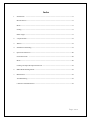
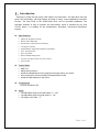
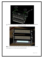
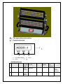
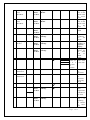
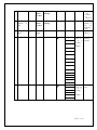
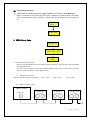
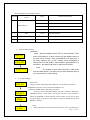
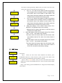
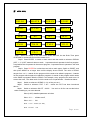
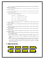
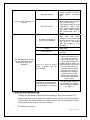
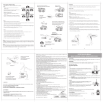
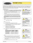
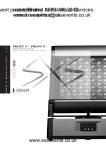
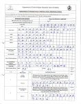
High Power LED Wash ILDW-4090583-00D-19 (Outdoor White) User Manual Page 1 of 16 Index 1. Introduction ----------------------------------------------------------------------------------------17 Main Function --------------------------------------------------------------------------------------17 Menu -------------------------------------------------------------------------------------------------17 Setting------------------------------------------------------------------------------------------------17 Beam Angle -----------------------------------------------------------------------------------------17 2. 2. Specification--------------------------------------------------------------------------------------18 3. Warnin ------------------------------------------------------------------------------------------------18 4. Installation and Setting-----------------------------------------------------------------------------18 5. Operation Instruction-------------------------------------------------------------------------------20 Panel Instruction ----------------------------------------------------------------------------------20 Menu -------------------------------------------------------------------------------------------------20 Linking and Input & Output Instruction --------------------------------------------------------23 6. DMX Mode/Linking Mode------------------------------------------------------------------------23 7. Maintenance -----------------------------------------------------------------------------------------25 Troubleshooting ------------------------------------------------------------------------------------25 Clearance and Maintenance-----------------------------------------------------------------------25 Page 2 of 16 Ⅰ、Introduction Welcome to using the high power LED washer from Neo-Neon. The light takes the high power LED technology, with long lifespan and high IP rating. It has temperature protection function. The each head of the VARIFLOOD DUO can be controlled separately. The operation interface is easy to operate and user-friendly, which is achieved by key and 5*7LED matrix. It is suitable for the entertainment, decorative, architecture illumination industry. z Main Function * * * * * * * * * * z Control Mode * * * * * z Adjust the brightness linearly Strobe effect adjustable Set all kinds of specifications manually 180 degree rotatable English Menu, digital tube brightness adjustable Over- heat protestion Auto Test Mode Record LED Running Time Can edit 3 programs with 30 scenes in total Time Switch DMX-512 Stand-alone program Install the independent running programs everyday during one week Drive 30 pieces of fixtures through the Master/Slave mode Install the DMX address of the fixture Configuration: 90 PCS 3W White LED z Angle: * The adjustable angle for double heads: 0°---120° * The adjustable angle for single head: 0°---90° * The angle of this item:5° Page 3 of 16 Ⅱ、Technical Specification DMX 512 AND Four channels LED Beam Angel: 120° All dim :0-100% Power consumption :300W Voltage:AC90--265V 50/60Hz Dimension:L660XW250XH496MM Weight:25.25KG(including the connecting line and the accessorie) Ⅲ、Security Warning: z z Please read the user manual carefully before using and abide by the operation introduction The fixture should be connected with the earth linked power supply, and the power voltage should be matched with the rated voltage The fixture is not attached with any accessory and just can choose the accessory which belongs to the manufacture The operating temperature should be not above 40℃ and not below -20℃ If there are some problems, please ask the professional for repair z z Note: When the power plug is not earth linked, please add grounding connection to the housing so as to avoid the damages of the accumulated static and charge. Ⅳ、Installation and Setup ⅰThe sketch map of hanging and installing The product can be locked on the truss by the lock nip: at first, put the nip into the truss and then screw down and adjust the screw. Page 4 of 16 2、This product can be laid on the flat ground by the rubber cushion under the bracket of the fixture shown as below: ⅲ、You can pull out the screw used for securing the power supply and then take out the power supply crust. The effect picture is illustrated as below:。 Page 5 of 16 Ⅴ、The operation instruction ⅰ. The panel instruction 1 2 3 4 1: LED Matrix display 3: Down 2: enter 4: Up Ii Menu Instruction No Item Content 1 Address A001 2 Boost boost Content of main menu Press Enter Button Change content Press Enter Button OFF the Sub-menu Sub-menu options How to enter submenu functions Set up the DMX starting channels Boost off Press Up/enter Page 6 of 16 3 White_0 Led Run Hour W0_H Press Enter to show Up/enter Delete 4 White_1 Led Run Hour W1_H Press Enter to show Up/enter Delete 5 Signal signal Unchangeable 6 brightness bright Press Enter to show Press Enter to show 7 Display Flip Or Not DSPFLI Press Enter to show Up/enter Change 8 Dmx delay Dmxdl Press Enter to show Up/enter Change 9 Time time 10 Factory Parameters FACT 11 Previous Parameters PREV 12 TEST White 13 Temperature Temp1 Operating time of the White LED on lower head) Operating time of the White LED on top head) Choose DMX Up/enter Change √ YEAR M/D H:M WEEK Press Enter for 2 or 3 seconds to confirm Recover the parameter Recover the parameter previously set up √ Press Enter to show Up/enter Change Press Enter to show Up/enter Change White √ Test the color temperature of RGB on the wash Temp2 14 Master Adjust the brightness of the screen Adjust the positive or opposite display Set up the period for the wash with no DMX signal Set up the inner time of the wash Set up the way of operating on Master or Slave unit Page 7 of 16 15 Slaver SlavID Press Enter to show Up/enter Change Set 16 Schedule Enable or not Sched Press Enter to show Up/enter Change 17 Program Run Pgrun Off 1,2,3 To see whether it runs as scheduled or not Program Selection 18 Program Set Pgset √ Prog SCENE FIXT up the Slave Number in Master/Sl ave Mode Press Enter for 2 or 3 seconds to confirm Edit the operating program Press Enter for 2 or 3 seconds to confirm Edit Time Event shutt Dim W0 W1 mac tm_h tm_m tm_s fd_h fd_m fd_s 19 Schedule Schedu √ SCNRUN event program day start end enable Page 8 of 16 ⅲ:Function Instruction: 1. 1. Reset after it is connected to power supply and below are steps to control RGB light. When it is connected to the power supply, the system is initialized. The reset interface of the display shows as below drawing. After two seconds, it will enter into the operation mode the last time it has run. Init… HELLO 2. DMX/Linking Mode HELLO MASTR=OFF A001 2.1 DMX Operation Instruction: Step One: When HELLO is shown and flicker. Press Up button to enter the main menu MASTER. Set MASTER to OFF. Step Two: Come back to the main menu for DMX address setting, such as A001. After connected to the controller, the fixture is under DMX control. 2.2 DMX Pin Assignment Male and Female DMX pin assignment: 2.3 Pin1 = Gnd Pin2 = Dmx- Pin3 = Dmx+ DMX Connection Chart: DMX Controller Dmx out In Dmx Out In Dmx Out In Dmx Out Fixture 1 Fixture 2 Fixture 3 Page 9 of 16 (Note Distribution Under DMX control) Channel 1 Name Value Function Description 0-3 Off 4-6 On 7-59 Strobe (20~1Hz) Shutter/Strobe others On 2 Dim 0-255 All dim Channel 3 W0 0-255 White Brightness of the Top Head 4 W1 0-255 White Brightness of the lower Head 1> SLavID. Menu Setting Instruction: Steps:When the display shows HELLO, the dot flickers. Then HELLO press UP/DOWM for a short second until the display switch to the main menu SLAVID. Then press MODE for a short time. It will show submenu XX(01-39),flicking. Press UP/DOWN to S L Av I D change the ID of this product. After selection, press MODE for a short time,the display will return to main menu SLAVID. Note: The setting of main menu SLAVID is valid under XX(1-39) auto and DMX mode. If you want to know more explicitly about it, you can read the Fix menu setting. 2> Fixt. Menu Setting: HELLO PGSET PRog. Fixt. Instruction: Step One: When the display shows HELLO , the dot flicker. Then Press UP/DOWN button for a short second until PGSET is set.. Then press MODE button until PRog is showed. Step Two: Press UP/DOWN button until Fixt is showed. Then press ENTER button for a short while., the display will show ALL or ODD or ENEN or MASTER or SLV01-SLV29, the dot flicker. Choose one of them and press Mode to go back to Fixt display. Then Press MODE button until PGSET is showed. . Note: 1. When the display of the master unit shows Fixt =ALL, it indicates that Page 10 of 16 ALL ODD EVEM MASTR SLvxx the master is running normally. Whatever the Fixt value of the slave units shows, they will receive the data from the master unit. 2: When the Fixt value of the master is ODD, the program of the master will run normally under the condition that the SLAVID value of the master is odd number. The slave fixture will receive data from the master under the condition that the SLAVID of the slave is odd .3: When the Fixt value of the master is EVEN, the program of the master will run normally under the condition that the SLAVID value of the master is even number. The slave fixture will receive data from the master under the condition that the SLAVID of the slave is even. 4 : When the display of the master fixture shows Fixt= MASTER. This indicates that it runs normally. Whatever the Fixt value of the slave is, it will not receive the data from master fixture. 5: When the display of the host computer shows Fixt= SLV01 (XX=(01-29), the master runs normally. The slave fixture will receive data from the master under the condition that the Fixt value of the slave fixture is SLV01. When the display of the host computer shows Fixt= SLV02 (XX=(01-29)), the master runs normally. The slave fixture will receive data from the master under the condition that the Fixt value of the slave fixture is SLV02.The rest will be deduced by analogy. 。 三.TSET Mode: HELLO TEST WHITE Instruction: Step 1 : When the main menu shows HELLO and flickers, press UP/DOWN button for a short second to switch to main menu TEST., then keep on pressing ENTER until submenu White is showed. Step 2:Press ENTER button,then you can see the white LED of both heads start to fade. Press MODE button for a short second, the white LEDs will be off. Step 3:After testing, press ENTER button for a longer time until the display shows TEST. Page 11 of 16 Ⅳ.AUTO MODE: HELLO MASTR PGRUN PGSET P R O G. SCENE F I X T. SHUTT DIM W0 W1 MAC TM-H TM-M TM-S FD-H FD-M FD-S SCRUN Step1:When the display of the main menu shows HELLLO, the dot flicks. Then press UP/DOWN for a short second until the master is on. Step2:Press ENTER to switch to main menu and then switch to submenu PGRUN (OFF, 1 ,2, 3) OFF means it does not work,1 represents that it operates in the first program. 2 represents that it operates in the second program. 3 represents that it operates in the third program. Step3:Press ENTER for a short time and exit to main menu. Switch to PGSET, and then press MODE for a longer time until the display shows PROG. The value of PROG ranges from 1 to 3. 1 stands for the program which needs to be edited is program1. 2 stands for the program which needs to be edited is program2. 3 stands for the program which needs to be edited is program3.Take the PROG=1 as example, every program can used to set 10 scenes the most, 1 the least each of which needs to set 18 parameters。Detailed as below: Step4: Switch to submenu SCENE (1-10), at first you set 1. Step5: Switch to submenu FIXT. = ALL,(about the FIXT has been introduced above). Step6: Switch to submenu SHUTT(0-255). You set it to 80.You can set the below value according to your own demand. Shutt (0-255): detailed parameter as below Shutt(0-3): all leds are off; Shutt(4-6): ON Shutt(7-59): Strobe (20~1Hz); Shutt(60-255): ON Page 12 of 16 Step7: Switch to submenu DIM0.This value cannot be set 0. The value is 255(the total brightness of light head ). Step 8:Switch to submenu W0 (0-255). Any value is OK. Set Value 255 for the white LED brightness of the top head Step 9:Switch to submenu W1(0-255)Any value is OK,Set Value 255 for the white LED brightness of the lower head Step 10:Back to sub-value MAC(0-255),Set 255(0-7)or(88-255)then the value W0, W1 is valid. If not, it will run the inner W value. MAC(0-7): Value W0, W1 is valid; MAC(8-31): Fade Mode Last for five seconds MAC(32-55): Fade Mode No time to remain MAC(56-255): The setting of W0,W1 is valid Step 11:Switch to submenu TM-H(0-23),The start value is 0 here, which is used to record running hours. Step 12: Switch to submenu TM-M (0-59), the start value is 0 here, which is used to record running minutes. Step 13: Switch to submenu TM-M (0-59), the start value is 0 here, which is used to record running seconds. Step 14: Switch to submenu FD-H (0-23), the start value is 0 here, which is used to record fading hours. Step 15: Switch to submenu FD-M(0-59), the start value is 0 here, which is used to record fading minutes. Step 16:Switch to submenu FD-S (0-59), the start value is 4,which is used to used to record fading seconds. Step 17: Switch to Switch to submenu SCRUN, when the display shows ON. This indicates that the set can run. When the display shows OFF, the parameter set is invalid. Step 18: The first scene of the first program is finished. Then switch to submenu SCENE (1-10). At first you select scene 2.Follwing the above step 4 to step 17, totaling 13 parameters. You can set the quantity of scene (maximum: 10 minimum: 1) according to your own requirement. 5.Timing Operation Modes: HELLO MASTR PGRUN SCHEDI EVENT P R O G. SCHED. D AY Page 13 of 16 S TA RT END ENABL Instruction: Step1:When the display shows HELLO, the dot flicks. Then press UP/DOWM for a short second. And then switch to main menu and set it ON. Step 2: Press Enter Button for a short second and back to main menu, switch to main menu PGRUN and set it OFF. Step 3: Press Enter Button for a short second and back to main menu, switch to main menu SCHED and set it ON. Step 4: Press Enter Button for a short second and back to main menu, switch to main menu SCHEDI. Then Press MODE for a longer time until the display shows EVENT (1-36). It can edit 36 pieces of time events for maximum. When the value is 1, edit event 1 operating parameter. Step 5:Switch to submenu PROG.(1,2,3), which indicate that the program event1 run, is shown, totaling 3, three programs under auto mode. You choose program1 here. Step6:Switch to submenu DAY to ensure which day this event runs. You can choose from Monday to Sunday. DAY=MON: indicates that this event can only run on Monday; DAY=TUE: indicates that this event can only run on Thursday; DAY=WED: indicates that this event can only run on Wednesday; DAY=THU: indicates that this event can only run on Thursday; DAY=FRI: indicates that this event can only run on Friday; DAY=SAT: indicates that this event can only run on Saturday; DAY=SUN: indicates that this event can only run on Sunday; DAY=ALL: indicates that this event can only run from Monday to Sunday. Step7: Switch to submenu START to ensure when the event starts run. The time is set at 08:00. Step8: Switch to submenu END to ensure when the event ends. The time is set at 23:00. Step9: Switch to submenu ENABLE = ON, which represent that the time is valid. Step10:When you repeat the steps 4 to steps 9, you can make other events run at scheduled time. (Remark:Set SCRUN of main menu PGSET =ON) ⅶ Temperature protection Mode: When the temperature of the fixture is higher than 50℃,the brightness will decrease correspondingly. When the temperature of the fixture is higher than 80℃, the fixture will be off automatically. After the light cool off to 70℃, it will light up again. Ⅵ. Daily Maintenance Trouble Shooting Trouble Reasons Trouble Shooting Page 14 of 16 No power supply One or many of fixtures do not work The fuse is burnt. The data connecting is wrong or uncompleted Whether it is in Master mode Wrong address The replacement is normal but the controller can not work well or there is no feedback There is a piece of fixture whose connector can not work normally The signal output of the controller is not matched with the connector of the signal receiving(PINS2—3 is wrong) ) Check whether the power supply is turned on and the power cable is connected well. Turn of the power supply. Then change into the same type of power supply. If the power supply is burnt continuously, there may have some problems with the power cable. Please ask professional staff to repair. Check, repair or change the data cable and check whether it is connected well and the signal input of the first fixture is connected with the output of the controller Set it in slave mode under DMX Mode Check the address and set uniformly After pulling the input and output signal cable out of the fixture and connect each other directly. Then check whether there is a problem with the fixture. If it works well after connecting, it proves that there is a problem with the signal connector of the fixture. According to the method--trouble shooting, then select the broken fixture and ask the professional staff to repair. Dial the polarity switch of the controller to “PHASE”, and exchange the address of PIN2—3 Cleaning and Maintaining Although we have already strengthened the credibility of the product in design, we always continue to keep the high level of quality and try our best to extend the lifetime of the product. We should maintain the product regularly and confirm the light to show itself under the best situation, which is necessary. I、 The cleaning of the fixture. Page 15 of 16 II、 The cleaning maintaining of the lens To ensure the optimum effect of the fixture, please clean each lens or the reflecting configuration. Please use the soft cotton cloth with little lotion to clean lens and protect the lens from damage. III、The regular examine of the cables Check the connecting cable, cloth cable and ground cable to ensure the security of the fixture of usage. Page 16 of 16