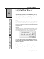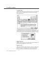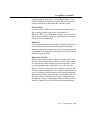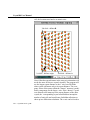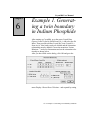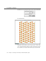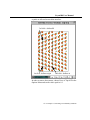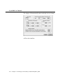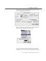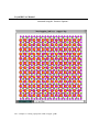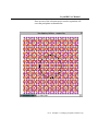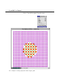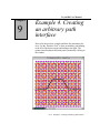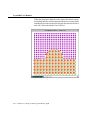
1
User Guide
to
Software Package for
Defect and Interface Modelling
in Crystalline Structures
CrystalKit User Manual
CONTENT
Page
Installation
Installing the Extensions
Installing the Hardware Protection Key
Activating the Hardware Key and Personalizing the Program.
1
1
1
1
Introduction
3
CrystalKit Menus
The File Menu
Selection to Pict
Window to Pict
Mac Screen to Pict
Write U.Cell to file
Write Xtal A/B to File
Write U.Cell to EMS file
Slice U.Cell to File
Recreate Interface
Page Setup
Print...
The Edit Menu
Undo
Show Clipboard
Create A/B Precipitate
Preferences...
The Crystal Data Menu
Crystal Data Menu
Create Crystal B
Show Crystal A
Show Crystal B
Orientation Menu
Set Orientation...
The Display Menu
Display Menu
Draw Crystal A
Draw Crystal B
Draw X-Section
5
5
5
5
5
5
5
5
5
6
6
6
6
6
6
7
7
8
8
8
10
10
10
10
11
11
12
12
13
CrystalKit User Manual
CONTENT
Draw Penetrating Lattices
Redraw Display
Make Movie
Play Movie
The Option Menu
Option Menu
Interface Options...
3D Atom Shading
Atomic Bonds
Boundary Tolerance
Remove Close Atoms...
Show Guides
Real Lattice
Reciprocal Lattice Options
Constrain Clicks to atoms.
Draw Bonds out of Layer.
Outline Atoms not in Layer.
Hilite 2D Atoms
The "Miscellaneous Menu"
Miscellaneous Menu
Draw Unit Cell Outline
Show Crystal during Rotation
Perspective...
Scale Volume...
Extend Crystal...
Randomize..
Page
14
15
15
15
15
15
15
17
17
18
18
18
19
19
20
20
20
20
21
21
21
21
22
22
23
23
CrystalKit Windows
Atom Window
Info Window
Tools Window
Main Drawing Window
25
25
25
26
26
CrystalKit Tools
Pointer
Info Tool
29
29
29
CrystalKit User Manual
CONTENT
Page
Move Atom Tool
Add Atom Tool
Delete Atom Tool
Interface Tool
Selection Tools
Ruler Tool
Define Unit Cell Tool
Rotate Tool
Lighting Tool
Animate Tool
Angle Tool
Plane Tool
Magnifying Glass
Color Picker Tool
29
30
30
30
31
31
31
33
33
34
34
34
34
34
General Information
Basis Atoms vs. Displayed atoms
35
35
Example 1. Generating a twin boundary in Indium Phosphide
37
Example 2. Creating a void in InP
41
Example 3. Creating a precipitate of InP in Copper
47
Example 4. Creating an arbitrary path interface
53
CrystalKit User Manual
CrystalKit User Manual
Chapter
I
Installation
The application CrystalKit and its associated files are all compacted in the file CrystalKit.sea which is a self-extracting
archive. After double-clicking on the application on the disk,
select a location on your hard disk for placement of the folder
“CrystalKit Folder” which will be created automatically as part
of the extraction procedure. There are two versions of CrystalKit supplied on your disk, CrystalKitPPC and CrystalKit68K
for the PowerPC and 680XX Macintoshes respectively. Only
one version will run on your machine.
Installing the
Extensions
(PowerPC and 68K) and the Math Library (PowerPC only) Skip
this step if you have already installed MacTempas)
Drag the files TRSecurity and MathLib as required from “CrystalKit Folder:Put In System Folder:Put In Extension Folder: to a
closed System Folder. The files will be placed in your extensions folder. Make sure you install the init TRSecurity before
installing the hardware protection key.
Installing the
Hardware Protection Key
Skip this step if you have already installed MacTempas
CrystalKit uses a hardware copy protection key which must be
installed on your computer. If you already have installed a key
for use with MacTempas, you do not need a second key to run
CrystalKit. Shut down the computer. With the computer turned
off, unplug the keyboard from the back of the computer and
plug the hardware key into the freed up port in the back of the
computer. Connect the keyboard cable to the other end of the
hardware protection key, making sure that all connections are
good. Restart the computer.
Activating the
Hardware Key and
Personalizing the
Program
Before CrystalKit can be run on a new system, you must run the
program, CrystalKitKey. Enter your name and affiliation as
appropriate. This program is not required again unless the program is moved to another machine.
Ch.
Installation - p.1
CrystalKit User Manual
Ch.
Installation - p.2
CrystalKit User Manual
Chapter
1
Introduction
CrystalKit is a general purpose program for modeling atomistic
defect and interface structures in crystalline material. The program works with either one or two crystals (A/B) which can be
perfect crystals or “unit cells” defined by CrystalKit in previous
sessions. CrystalKit accepts files created in MacTempas and
also outputs files in the MacTempas file-format. Optionally, the
program can also read and write files in the EMS supercell format. When creating precipitates or geometric interfaces/grainboundaries, the program works with crystals A and B which
may or may not be the same crystalline structure. In order to
create point defects, voids, interstitials etc., it is necessary only
to work with a single crystal. CrystalKit can be used to visualize
crystal-structures and chemical bonds. Angles and distances are
easily measured and planes can be identified. Atoms can be
moved either single or in groups and can be cut from and pasted
into the structure. New atoms are added by the click of the
mouse. It is also possible to view the kinematical diffraction
patterns for a given crystal.
Ch. 1 Introduction - p.3
CrystalKit User Manual
Ch. 1 Introduction - p.4
CrystalKit User Manual
Chapter
2
The File Menu
CrystalKit Menus
Unlike most Macintosh Applications, the File Menu has no
Open... menuitem. The File Menu is not used to open existing
CrystalKit files, but rather to store created defects as structure
files or create Pict files from the display.
The first three menu-commands
Selection to Pict
Window to Pict
Mac Screen to Pict
are used to create a PICT file from either the current selection,
(created by the selection tool), the CrystalKit Display Window
or the entire Macintosh Screen.
Write U.Cell to file
is used to write a structure file ready for simulation in
MacTempas using a unit cell that has been defined by the use of
the “Define Unit Cell” tool.
Write Xtal A/B to File
writes a structure file using the currently defined data of either
crystal A or Crystal B. This is useful for saving a structure that
has been defined within CrystalKit and also for structures that
have been modified since they were read in. Note: See General
Info for use of the Option Key in conjunction with saving the
structure.
Write U.Cell to EMS file
is for writing a unit cell defined with the “Define U.C. Tool” as
an EMS compatible file for further manipulation.
Slice U.Cell to File
will instead of writing the defined unit cell out as a single structure file, write the structure out as n separate files where the z-
Ch. 2 CrystalKit Menus - p.5
CrystalKit User Manual
direction has been divided into n equal slices.
Recreate Interface
When CrystalKit saves a unit cell defined with the Unit Cell
Tool, it also saves information regarding the two crystals, their
orientation relationship and other settings. Thus when the user
opens a file through the “Recreate Interface...” command, the
two crystals are loaded into crystal A and B and the display
shows the interface identical to when the unit cell was defined.
Page Setup
is the normal Print Dialog for page setup.
Print...
will print either the content of the image window or the content
of any selected region.
Quit
Exits CrystalKit
The Edit Menu
The Edit Menu
serves a dual function. First it provides for the normal cut, copy,
etc. functions that allow all Macintosh applications to share
data. Thus one can bring any picture displayed in CrystalKit
into any other Macintosh application. However, by using the
Option key in conjunction with Cut, Copy, Paste and Clear, the
operation takes place on the atoms that are visible in the display.
It is important to remember that in order for the “special” version of Cut, Copy, etc. to work, the Keyboard equivalents can
not be used, the menu commands must be invoked by selecting
them with the mouse. The use will be further described in a
working example.
Undo
is not implemented.
Show Clipboard
Ch. 2 CrystalKit Menus - p.6
CrystalKit User Manual
shows the content of the clipboard in its own window.
Create A/B Precipitate
allows the user to create a precipitate of one of the crystals
within the other. In order for this to work, the user defines two
crystals, specifies the orientation relationship, an interface plane
and a zone axis. The user then selects “Draw Penetrating Lattices” from the Display Menu. After the program draws the penetrating lattices the user creates a “selection” with one of the
“Selection Tools” and chooses “Create A or B Precipitate” to
keep A or B within the selection and B or A outside the selection.
Preferences...
is used to set the preferences associated with CrystalKit. One
set of parameters determines the preference values for the
microscope values and the crystal thickness to be used by
MacTempas for doing an image simulation.
Atomic radii can be set to be either covalent or ionic by default.
Individual atomic radii can always be changed manually by the
user at any time. The maximum number of atoms that the program can handle is set through the preference dialog. As is indicated, one also must make sure that adequate memory is
Ch. 2 CrystalKit Menus - p.7
CrystalKit User Manual
allocated to the program by selecting the program in the finder
and requesting “Get Info” from the menu and setting the
amount of memory that is allocated to the program.
Crystal Data
Menu
The Crystal Data Menu
is where the crystals A or B gets defined. Each crystal can be
either read in from an existing file, entered manually or set
equal to a structure that has already been read in.
Create Crystal A
Create Crystal B
brings up the following choice
If the data is read from file, the normal Apple file-dialog
appears, allowing the user to select an input file. If the Option
key is held down when selecting “Read from File...” the program allows the user to choose an EMS file to be read in. No
check on the filename is performed and the file must be a valid
supercell EMS file.
The normal CrystalKit file shares the data format with the
MacTempas program and has an extension of type ".at".
Ch. 2 CrystalKit Menus - p.8
CrystalKit User Manual
In addition, the resource fork can hold data about the two crystals that went into defining the unit cell if the structure was created by CrystalKit through the use of the “Unit Cell Tool”.
If the data is to be entered from within the program, the following dialog box appears, prompting for the relevant information.
If the crystal can be defined as one of the 230 spacegroups
defined in the international table of crystallography, the user
selects from the pop-up menu the type of crystal-structure
(monoclinic, orthorhombic, cubic, etc.), and is presented with a
choice of possible spacegroups for the selected crystal structure.
The number of symmetry operators associated with the crystal
is automatically created by the program and the user only needs
to fill out the data for the atoms in the basis (motif) after the
Ch. 2 CrystalKit Menus - p.9
CrystalKit User Manual
data for the lattice parameters are entered.
Both the total set of atoms in the entire structure and the set of
symmetry operators can be displayed by clicking on the two
buttons “Atoms ...” and “Symop ...”
Show Crystal A
Show Crystal B
shows the user the data associated with the two crystals. The
data is presented in the same fashion as when a new structure is
created within the structure. The data can be edited to modify
the structure.
Orientation Menu
Ch. 2 CrystalKit Menus - p.10
has only one menu-command
Set Orientation...
which is used to specify the orientation relationship between the
two crystals. The orientation relationship between the two crystals can be defined in two ways. The usual way to define the orientation relationship between two different crystals is to define
two parallel planes and two parallel directions for the two crystals. It is also possible to define a common orientation axis and a
rotation angle. Keep in mind that the axis/angle pair specifica-
CrystalKit User Manual
tion is only properly defined in the special case where the two
crystals are identical. In this case, the two lattices are first oriented with their lattice parameters parallel to each other, before
the rotation is performed about the common axis.
This allows for quickly defining a twin boundary in a crystal. In
addition to defining the orientation relationship, the dialog is
also used for defining the interface plane between the crystals
and the zone axis. The interface plane cuts through the two lattices and crystal A is retained on one side of the plane and crystal B on the other side. This plane can be defined with respect to
either crystal A or crystal B. The zone axis is used for defining
the orientation for viewing direction and CrystalKit currently
enforces the restriction that the zone axis must be perpendicular
to the interface plane. Thus CrystalKit currently does not allow
easily for the creation of inclined interfaces.
Display Menu
The Display Menu
is used to visually display the crystals or cross-section of crystals. In order to visually define a new unit cell with defects,
interstitials etc., the user must first draw the crystal. In the case
where the user wishes to define a unit cell containing an interface between two crystals, a cross-section showing the interface
must first be drawn.
Ch. 2 CrystalKit Menus - p.11
CrystalKit User Manual
Draw Crystal A
Draw Crystal B
allow the user to display either a single unit cell or a cross-section of either crystal given a specified viewing direction.
The field of view and the specification of the zone axis are only
associated with drawing a crystal cross-section and the zoneaxis does not have an effect when displaying a single unit cell.
When the display of a single unit cell is specified, the unit cell is
always initially drawn in the [001] orientation. The crystal can
be rotated into an arbitrary orientation with the Rotate Tool.
There is an option to specify a viewing direction as either in
terms of a real space direction (uvw) or a reciprocal direction
(hkl). This is useful when one wants to view a particular set of
planes when the unit cell is non-cubic. In cubic crystals the two
are identical. In non-cubic crystals, they are in general different,
but the reciprocal direction hkl is always perpendicular to the
plane given by the indices hkl. More than a single unit cell can
be viewed in the “Crystal Unit Cell” view together with the
Ch. 2 CrystalKit Menus - p.12
CrystalKit User Manual
option of displaying specific planes
Draw X-Section
is used to display a cross-section of a defined interface. The
command is only active after the user has defined two crystals,
Ch. 2 CrystalKit Menus - p.13
CrystalKit User Manual
their orientation relationship, interface plane and zone axis.
The specified zone axis defines the viewing direction. The values entered in the field of view is used to define the size of the
crystalline material drawn. The interface plane is always drawn
horizontally. It is important to remember when the interface is
drawn, both crystals are allowed to "touch" the interface plane.
This means that there are atoms from both crystals at the interface plane even though they may be obscured by other atoms or
sit at the same site. By specifying how close either crystal A or
B are allowed to come to the interface plane, this "double occupancy" can be resolved.
Draw Penetrating Lattices
uses the same information as draw cross-section, but allows
both crystals to be drawn on either side of the interface plane.
This way it is easy to see how the two crystals fit together and
one can visualize any coincidence lattice. This command is also
used in order to define a precipitate of one of the crystals in a
matrix of the other. Creating precipitates is done by first drawing inter-penetrating lattices and using the commands in the
“Edit ” menu for creating either an A or B precipitate.
Ch. 2 CrystalKit Menus - p.14
CrystalKit User Manual
Redraw Display
redraws the view in case updating the display is required.
Make Movie
is used to create an animated sequence of either crystal A or B
rotating 360 degrees. A selection rectangle must be defined
which shows the size of the “Frame”.
Play Movie
just plays back a movie created by Make Movie
Option Menu
The Option Menu
sets a number of optional parameters.
Interface Options...
brings up the following dialog box which controls many parameters determining the interface between two crystals.
Top Crystal
determines whether crystal A or crystal B is to be used towards
Ch. 2 CrystalKit Menus - p.15
CrystalKit User Manual
the top of the display, above the interface plane.
Closest proximity of atoms to the interface
determines how close atoms from either crystal are allowed to
be to the interface plane. Allowing both atoms to touch the
interface will usually result in un-physical structures and also
may obscure the fact that two atoms (one from each crystal)
may occupy the same site without any visible indication
thereof. This can easily happen when the same crystal is used
for A and B and two atoms of the same type occupies the same
position at the interface. The first indication that something is
wrong may be during an image simulation where the interface
plane shows wrong image contrast due to excess atoms at the
interface plane. The value to be used is in Ångstrøm.
Translation of grains
allows the user to translate either of the two crystals with
respect to the interface. These are rigid body translations. Units
are in Ångstrøm.
Rotations of grains
will rotate A and/or B with respect to the viewing (z) axis. The
rotation is used in addition to the parameters set in the orientation dialog box. Thus the grains are first oriented as specified in
“Set Orientation” and then additionally rotated by the angle
specified.
Rotation of entire cross-section
is a rarely used option that allows for a slight rotation of the
entire field of view to be rotated around the x-axis of the display. The x-axis is also the direction along the interface, going
from horizontally from left to right in the middle of the display
window.
Depth of cross-section
is used to set a specific value for the extent of a cross-section
(using either one or two crystals). Normally the depth is automatically set by the program to be the length of the zone-axis
Ch. 2 CrystalKit Menus - p.16
CrystalKit User Manual
for the crystal, that is one repeat distance in the z-direction of
view. However, by checking the checkbox and inputting a value
in Å, the depth will be set to the value entered by the user.
Strictly speaking the option for the depth of the view does not
belong in this dialog since it is also used when displaying a
cross-section view for a single crystal. Thus the depth is not
necessarily related to an interface.
3D Atom Shading
will cause the atoms to be drawn as shaded spheres with lighting conditions specified by the “Lighting Tool”
Atomic Bonds
allows the user to specify up to 5different types of bonds to be
drawn between atoms. The user specifies the two atoms
between which to draw a bond and the minimum and maximum
distance between the two atoms for when to draw a bond.
By clicking on the line for the bond, it is possible to choose the
Ch. 2 CrystalKit Menus - p.17
CrystalKit User Manual
color for the bond the line-style and the width of the bond.
Boundary Tolerance
has been added to allow the user how close to zero or 1 a relative atomic coordinate can be without being considered to lie on
the boundary (0 and 1). Default value is 0.001
Remove Close Atoms...
will initiate an attempt by the program to determine if two
atoms are too close and to remove atoms that are within a specified distance.
Show Guides
will turn grid lines on or off. The default gridlines appear as a
vertical and a horizontal line that can be positioned anywhere
by dragging the line with the pointer tool. Additional vertical
and horizontal lines can be added by dragging with the mouse
from the “grayed” area at the edge of the image window into the
Ch. 2 CrystalKit Menus - p.18
CrystalKit User Manual
window. These guides can be very useful to mark positions on
the screen when creating interfaces.
Real Lattice
will cause the following pop-up menu to appear. The image
window can show the real lattice (default), the reciprocal lattice
or both lattices at the same time. Zooming using the Magnification Tool will only effect the drawing of the real lattice. Thus if
both lattices are drawn, the real unit cell can be reduced while
keeping the diffraction pattern constant.
Reciprocal Lattice Options
sets options related to the display of the reciprocal lattice. The
camera length determines the scale of the pattern. The divergence angle sets the size of the diffraction spot which also is
scaled by the structure factor.
The maximum reciprocal lattice vector is set through the dialog
together with options for labelling the pattern. The options are i)
indexing the pattern (hkl), ii) showing structure factors, iii)
showing d-spacings and iv) showing length of reciprocal lattice
vectors. If the “Show non-reflecting points” is checked, the program will also display points in the reciprocal lattice that are in
non-reflecting positions.
Ch. 2 CrystalKit Menus - p.19
CrystalKit User Manual
Constrain Clicks to atoms.
Normally when using the mouse to select a point for defining a
unit cell or to measure a distance, the program only allows click
inside an atom. If this option is non-checked, it is possible to
mark positions that are not associated with atom positions. This
effect can usually also be accomplished by holding down the
Option Key when clicking in the window. Note that the status
bar at the bottom of the main window will often give useful
information when not constraining clicks to atomic positions,
such as the angle with the x-axis when selecting a unit cell with
the Unit Cell Tool.
Draw Bonds out of Layer.
When a cross-section or an interface is being viewed it is possible to select which atomic layer to display through the pop-up
menu in the lower left corner of the image window. If the “draw
bonds out of layer” is unchecked, the program only will draw
atomic bonds that fall within the displayed layer. If the option is
checked the program will also draw bonds to atoms that do not
lie in the displayed layer.
Outline Atoms not in Layer.
By default atoms that do not lie in the displayed layer are not
drawn. If this option is checked, atoms that lie in other layers
are outlined by a non-filled circle.
Hilite 2D Atoms
This will turn on/off the light circle used to create a highlighting
effect when drawing the atoms as 2D circles.
Ch. 2 CrystalKit Menus - p.20
CrystalKit User Manual
Miscellaneous
Menu
The "Miscellaneous Menu"
is a selection of commands outlined below.
Draw Unit Cell Outline
determines whether the crystalline axes should be drawn when
the crystal is drawn. By default the crystalline axes and the field
of view boundaries are drawn.
Show Crystal during Rotation
. By default the crystal is shown “real time” when the rotation
tool is used. If this option is not used, the unit cell is only
redrawn when the mouse is released and only an outline of the
unit cell is shown during the rotation.
Ch. 2 CrystalKit Menus - p.21
CrystalKit User Manual
Perspective...
brings up the following dialog. If the option to use perspective
is checked, the unit cell will be drawn in perspective with the
distance to the cross-over indicated by the figure determined by
the parameter set by the user.
Scale Volume...
allows the user to scale the bounding volume of the defined unit
cell such that the unit cell stays fixed and the bounding volume
determined by a,b and c are scaled according to the input in the
following dialog. Note that this operation cannot be undone.
Ch. 2 CrystalKit Menus - p.22
CrystalKit User Manual
Extend Crystal...
will create a new unit cell by extending the previously defined
unit cell by a given integral number of unit cells in each direction a,b and c. Note that this operation cannot be undone.
Randomize..
rings up the following dialog.
Ch. 2 CrystalKit Menus - p.23
CrystalKit User Manual
It is a fairly rude attempt to create an amorphous structure by
displacing atoms in random directions according to the options
set in the dialog above. By default, each atom is displaced by a
specified displacement in a random direction and a displacement satisfying the criteria that two atoms are not closer than a
specified distance is sought within a maximum number of
attempts. If the distance criteria is not met for the maximum
number of attempts, the program allows the last displacement
and notifies the user at the end how many atoms do not meet the
distance criteria. It is also possible to specifically give minimum
distances for any specific two atoms. The atoms are specified by
selecting the atom by clicking in the “Atom Type” and then
clicking in the box for the “Atom” to deposit the selected atom.
In order to create an amorphous structure of a given size, it is
necessary to first display a cross-section of the required dimensions, marking a unit cell to set the boundaries and then randomizing. The unit cell can also be marked after randomizing,
although it may be necessary to uncheck the “Constrain click to
atoms” in order to mark the appropriate volume.
Ch. 2 CrystalKit Menus - p.24
CrystalKit User Manual
Chapter
3
CrystalKit Windows
CrystalKit has four main windows. These are the atom window,
the info window, the tools window and the main drawing window. The windows are described in more detail below.
Atom Window
This window shows the different atom types in the crystal(s)
that are defined. The relative radii of the atoms are represented
by the size of the colored circles and the colors correspond to
the ones used in drawing the atoms. By double-clicking on one
of the circles, the atomic radius can be changed. When the
color-picker tool is active, the color of the atom can be changed
by clicking on the circle and choosing a color from the pop-up
window.
Info Window
This window is used for reporting information to the user. Information such as inter-atomic distances, angles and information
regarding crystalline planes is written to this window. Additional information is also shown in the status line at the bottom
of the main drawing window.
Ch. 3 CrystalKit Windows - p.25
CrystalKit User Manual
Tools Window
This window contains the various tools for controlling the
actions of CrystalKit. The tools are described in further detail in
the next chapter on the CrystalKit tools.
Main Drawing Window
This window is used for all drawing of unit cells etc.
When drawing a cross-section, the layer control at the bottom of
the window can be used to display only atoms in specific layers.
The control is a pop-up menu, displaying the various heights in
Ch. 3 CrystalKit Windows - p.26
CrystalKit User Manual
Ångstrøm containing layers of atoms. By selecting one of these
layers, only atoms in this layer is displayed. When operating on
atoms, only atoms in the currently selected layer are effected.
Ch. 3 CrystalKit Windows - p.27
CrystalKit User Manual
Ch. 3 CrystalKit Windows - p.28
CrystalKit User Manual
Chapter
4
CrystalKit Tools
All the tools that CrystalKit can use are defined here. The user
selects a tool by clicking in the corresponding area. That tool is
active until the user chooses another tool. The cursor will normally change to indicate which tool is currently active.
Pointer
The Pointer Tool is used only when the user wants no other tool
to be active. It has no function except for insuring that no other
tool is active. It should also be the active tool when creating and
dragging grid lines
Info Tool
When this tool is active, clicking on an atom will bring up information regarding that particular atom. Normally a dialog box
shows the data and these can be edited in the normal way.
In the case when an interface is drawn, the data is displayed in
the INFO window. By holding down the Option key, the normal
dialog box is displayed.
Move Atom Tool
Use this tool to move atoms around. It only works when an
interface or a crystalline cross-section is drawn. It is important
to note that with many of these tools, all changes are lost after
redrawing.
Ch. 4 CrystalKit Tools - p.29
CrystalKit User Manual
Add Atom Tool
Add an atom at the location of the mouse click. At the time the
tool is activated, a dialog comes up to allow for specifying
which atom to add.
A separate dialog appears allowing the specification of the
Debye-Waller factor, the Occupancy factor and the height of the
atom in the z-direction (perpendicular to the plane of viewing).
Delete Atom Tool
Deletes single atom. Does not work when viewing a single crystalline unit cell (displaying Crystal A or B).
Interface Tool
When a cross-section with an interface is drawn, use this tool to
define an interface of arbitrary shape. Start to the left of the
drawn crystalline section and mark points that defines the
Ch. 4 CrystalKit Tools - p.30
CrystalKit User Manual
boundary until the other end is reached. Backtracking is not
allowed. When the last point is specified, the interface will be
redrawn with the specified path as the "interface plane".
Selection Tools
Use these tools to define a selection of various shapes for cutting, copying, defining a region for a precipitate etc.
When the “Shift” key is held down, a square or a circle will be
drawn. When using the region tool, the path must be closed by
ending up at the starting point.
Ruler Tool
Used to measure interatomic distances. Normally all clicks are
constrained to atom positions and the program will sound a
warning sound when an atom close to the mouse down position
is not found. If the Option key is held down, the click is not constrained to atom positions.
Define Unit Cell Tool
When a cross-section is drawn, either of a single crystal or an
interface, this tool allows the creation of a unit cell for writing
to a structure file. Mark first the origin, then one lattice vector
(A) and then finally the second lattice vector (B). By using
Write U.Cell To File, this unit cell is written to a structure file.
One can continue defining unit cells, each one replacing the previous. All changes to the structure, such as moving atoms and
deleting atoms will be reflected in the created structure file. If
the cross-section is drawn once more, these changes are lost.
Normally the cursor is constrained to fall on an atom. However,
when the “Option” Key is held down when marking the unit
Ch. 4 CrystalKit Tools - p.31
CrystalKit User Manual
cell, the locations need not be on atomic sites.
3rd click - defines B
1st click - defines origin
2nd click - defines A
Note: Often the repeat distance in the zone-axis orientation will
not be the same for the two crystals A and B. The program will
use the largest repeat distance as the C axis, but will fill the
other crystal with atoms only to its repeat distance. The occupancy factor of the atoms within the “shorter” structure is modified to compensate for the larger c-axis. If the “shorter” Crystal
was allowed to fill atoms up to the repeat distance of the other
crystal, the “corresponding crystal would hold an incomplete
number of unit cells and would cause forbidden reflections to
show up in a diffraction calculation. The c-axis can be forced to
Ch. 4 CrystalKit Tools - p.32
CrystalKit User Manual
an arbitrary value by fixing the x-section depth (from the Option
Menu).
Specifying a depth of the cross section
Rotate Tool
When a crystalline unit cell is viewed (Display Crystal A/B),
this tool is used to rotate the crystalline unit cell into any orientation. Click in the main window and hold down the mouse button while moving the mouse. If the “Shift” key is held down as
the pointer is moved, the rotation is about the axis perpendicular
to the screen.
Lighting Tool
When the 3D Option is used in drawing atoms, this tool is used
to define the direction of light. Click in the center of main window and hold down the mouse button while moving the mouse
to change the direction of the light. Because the circle showing
Ch. 4 CrystalKit Tools - p.33
CrystalKit User Manual
the shading is drawn at a distance from the location of the cursor, it may be necessary to press down the mouse with the cursor in the center of the screen.
Animate Tool
When a crystalline unit cell is viewed (Display Crystal A/B),
this tool is used to continuously rotate the unit cell. The rotation
starts by clicking in the main window. It stops when the mousebutton is pressed down a second time. It may be necessary to
keep the mouse depressed for a short time to stop the rotation if
the drawing of the unit cell takes a long time.
Angle Tool
Use this tool to measure the angle between two directions (3
atoms)
Plane Tool
Use this tool to determine the plane and the planar spacing by
clicking on two atoms in the same plane.
Magnifying Glass
Clicking in the display magnifies a drawn unit cell by 10% per
click. Holding down the Option Key demagnifies. By holding
down the Shift Key the increments in magnification/reduction
changes to 100%.
Color Picker Tool
Used to change the color associated with an atom species.
When this tool is active, click in the colored circle in the atom
window (actually anywhere in the rectangle) and choose any of
the 16 different colors.
Ch. 4 CrystalKit Tools - p.34
CrystalKit User Manual
Chapter
5
Basis Atoms vs.
Displayed Atoms
General Information
The structures referred to as Crystal A and B can be modified by
the user and saved to a new file by the menu commands “Write
Xtal A/B to File”. Normally this structure is associated with the
list of “basis-atoms”. Thus if one displays the list of atoms
(basis or atoms) in the dialog “Show Crystal A/B”, one can only
modify the list of “basis-atoms”. This is because the “atom-list”
is generated from the “basis-list” by the application of the symmetry operators. If the only symmetry operator is x,y,z (the
identity operator), the “atom-list” and the “basis-list” are identical in content, but the program still maintains a separate list for
the two. When one displays a single unit cell of a structure, as in
“Display A”, the atoms drawn on the screen correspond to the
“atom-list” plus the equivalent atoms drawn at corners and
faces. For example in the list, one only has an atom at
(x=0,y=0,z=0), but on the screen there will be additional atoms
at (1,0,0), (1,1,0), (1,1,1), (0,1,0) etc... If one modifies the
structure by typing in new information in the “basis-list”, this
information will be reflected in the structure if one uses the
command “Write Xtal A/B to File” to save the new structure.
However, it is possible to modify the structure in a different
way. When one draws a single unit cell on the screen and possible the rotate tool to view the structure from a convenient direction, one can get information on a single atom by clicking on it
with the info tool (?) selected. This information can be modified
by typing in new values for the coordinates, changing the atom
type etc., and one will see the modifications on the screen. The
information that is changed is maintained in the “atom-list”, not
the “basis-list”. Thus if the structure is saved using the command “Write Xtal A/B to File”, these changes will not be
reflected in the saved structure. However, if the Option Key is
held down when invoking the saving of the structure, the “atomlist” will be saved, not the “basis-list” and your changes will be
written to the file. It is important to realize that one could not
Ch. 5 General Information - p.35
CrystalKit User Manual
change the atom at (1,1,1) and have that change reflected in the
new structure. The atom at (1,1,1) is not in either list and is only
drawn to show the unit cell corners. One can either think of
each the corner-atoms contributing 1/8th of an atom to the unit
cell, or that the atom at (0,0,0) is wholly within the unit cell and
that the other corner atoms belong to neighboring unit cells. The
latter convention is used in CrystalKit
Ch. 5 General Information - p.36
CrystalKit User Manual
Chapter
6
Example 1. Generating a twin boundary
in Indium Phosphide
After starting up CrystalKit, go to the menu Crystal Data.
Choose Create Crystal A (Read From File...) and select the file
InP.at. Then proceed to define Crystal B (Create Crystal B ->
Same As A). Now both crystals are defined and the orientation
relationship must be defined. Choose the menuitem “Orient.
Relations...” under Set Orientations and set the orientation relationship as shown below.
After you have filled out the dialog, click OK and go to the
menu Display. Choose Draw XSection... and respond by setting
Ch. 6 Example 1. Generating a twin boundary in Indium
CrystalKit User Manual
the field of view to 30 by 40. (Units are in Å). The result should
be as shown below.
If you now want to define a unit cell, just use the “”Define Unit
Cell” Tool and mark the Origin, A and B. At this point you will
have a double set of atoms at the interface plane, because both
Ch. 6 Example 1. Generating a twin boundary in Indium Phosphide - p.38
CrystalKit User Manual
crystals are allowed to touch the interface.
3rd click - defines B
1st click - defines origin
2nd click - defines A
In order to remove these atoms, choose Prox. of Top & IF in the
Options Menu and set the value equal to 0.1.
Ch. 6 Example 1. Generating a twin boundary in Indium
CrystalKit User Manual
The display will automatically redraw and only one set of atoms
will be at the interface.
Ch. 6 Example 1. Generating a twin boundary in Indium Phosphide - p.40
CrystalKit User Manual
Chapter
7
Example 2. Creating
a void in InP
This example only requires one crystal to be defined. We will
use the same crystal as in the previous example. It is assumed
that crystal A is already defined as InP. Choose Draw Crystal A
under the Display Menu and fill out the dialog as shown below.
Click OK and a cross-section of the crystal will be drawn.
Use the “Polygon Selection” Tool to mark an area that will be
cut out.
Ch. 7 Example 2. Creating a void in InP - p.41
CrystalKit User Manual
With the selection active, move to the Edit Menu and while
holding down the “Option” key, choose Cut. All the atoms
within the selection are erased.
Ch. 7 Example 2. Creating a void in InP - p.42
CrystalKit User Manual
Now use the “Define Unit Cell” Tool to mark an unit cell.
Ch. 7 Example 2. Creating a void in InP - p.43
CrystalKit User Manual
Save the marked unit cell as a structure file by using the menu
command “Write U.Cell to file....”
which brings up the standard Save File Dialog
After the file has been saved, load it back in as Crystal A
and the new supercell can be manipulated as a normal structure
Ch. 7 Example 2. Creating a void in InP - p.44
CrystalKit User Manual
By displaying more than a single unit cell, it is clear that any
HRTEM image simulated from this new structure will corre-
Ch. 7 Example 2. Creating a void in InP - p.45
CrystalKit User Manual
spond to a periodic array of voids as shown below.
Ch. 7 Example 2. Creating a void in InP - p.46
CrystalKit User Manual
Chapter
8
Example 3. Creating
a precipitate of InP
in Copper
Although you won’t probably ever be looking at InP precipitates in Copper, this example still illustrates one method of creating precipitates. The key to creating a precipitate is to operate
with two crystals, defining the crystalline relationship between
the two materials, the zone axis and an interface plane. The
interface plane in this case serves as to orient the view of the
material. When the “interface” is shown as penetrating lattices,
the “Create Precipitate...” menu commands can be used to actually create the precipitate.
Load Copper as Crystal A and InP as Crystal B. The two crystals will load and display as shown below.
Ch. 8 Example 3. Creating a precipitate of InP in Cop-
CrystalKit User Manual
Ch. 8 Example 3. Creating a precipitate of InP in Copper - p.48
CrystalKit User Manual
Now define the orientation relationship. In our case, it is a cubeon-cube relationship as shown below.
Instead of drawing the XSection which would show an interface
structure, use the command “Draw Penetr. Latt...”
This will result in the following drawing of the two interpenetrating lattices. The two lattices can be additionally rotated and
Ch. 8 Example 3. Creating a precipitate of InP in Cop-
CrystalKit User Manual
translated using the “Interface Options”.
Ch. 8 Example 3. Creating a precipitate of InP in Copper - p.50
CrystalKit User Manual
Now use one of the selection tools to mark a region that will
cover the precipitate as shown below
Ch. 8 Example 3. Creating a precipitate of InP in Cop-
CrystalKit User Manual
Select “Create B Precipitate” from the menu.
Ch. 8 Example 3. Creating a precipitate of InP in Copper - p.52
CrystalKit User Manual
Chapter
9
Example 4. Creating
an arbitrary path
interface
Proceed as the previous example and draw the penetrating lattices. Use the “Interface Tool” to draw an arbitrary path starting
to the left of the drawn region and ending to the right. The
points can not backtrack and each point is marked by clicking in
the window.
Ch. 9 Example 4. Creating an arbitrary path interface -
CrystalKit User Manual
When the last point is defined (to the right of the drawn region),
the defined interface will be automatically drawn. Atoms can be
individually moved or deleted to fine tune the interface before a
unit cell is selected with the Unit Cell Tool.
Ch. 9 Example 4. Creating an arbitrary path interface - p.54