1
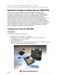
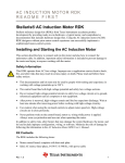
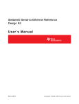
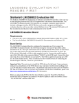
S2E RDK README FIRST Stellaris® Serial-to-Ethernet (S2E) Module RDK Stellaris reference design kits (RDKs) from Texas Instruments accelerate product development by providing ready-to-run hardware, example software, and comprehensive documentation including hardware design files. The Serial-to-Ethernet (S2E) Module RDK includes all the necessary cables, hardware, and software to run a demo application out of the box. The compact design is based on the LM3S6432 Stellaris microcontroller, a highly integrated ARM® CortexTM –M3 microcontroller with integrated 10/100 Ethernet MAC and PHY, 50-MHz performance, and ample single cycle on-chip Flash and SRAM memory for efficient network traffic handling. The S2E module includes one 10/100 Ethernet port and two serial ports with flexibility that includes both RS-232 and CMOS/TTL level signaling, flow control, and hardware support for both synchronous and asynchronous serial communication. Development of software for the S2E module is simplified by using the extensive Stellaris example software and ARM development tools from our tools partners. The most common application for the S2E module is for augmenting legacy products that contain a serial port for a configuration or control interface. Simply installing a S2E module into the legacy serial device provides instant networking capability with no major board redesign or software changes, a tiny form-factor for unobtrusive implementation, and cable lengths much longer than what is available for simple serial connections. Installing and Using the S2E Module RDK Kit Contents The S2E Module RDK includes the following items: • • • • • • • Stellaris Serial-to-Ethernet Module (MDL-S2E) S2E connector board Retractable Ethernet cable DB9 serial cable USB cable for module power JTAG/SWD adapter to standard 20-pin header This Quickstart Guide, User’s Manual, Software Reference Manual, Board Data Sheet, source code, bill of materials (BOM), schematics, and Gerber files on CD Rev. 1.5 1 S2E RDK README FIRST Quickstart Application The S2E module comes preprogrammed with a quickstart application. Once you have powered the board, the application runs automatically. The application provides a means of accessing the UART serial ports on the LM3S6432 microcontroller through a network. The serial port on the LM3S6432 can then be connected to the serial port on a non-networked device, providing the ability to access the device via a network. This can be useful to overcome the cable length limitations of a serial connection and to provide networking capability to existing devices without modifying the device’s operation. The application supports Universal Plug and Play (UPnP) for device discovery allowing the PC to detect the networked device. Click the UPnP device icon in “My Network Places” on your PC to load the website served up by the S2E module into your web browser. The website allows for various configurations of the S2E module. Once you have powered the board, the application runs automatically. The application attempts to contact a DHCP server to acquire an IP address. If unable to get an IP address from a DHCP server, the application acquires a link local IP address using the AutoIP protocol. Note: The quickstart application requires Universal Plug and Play (UPnP) support. This support is provided by default in Windows XP and Windows Vista, but must be enabled. See below for details on enabling UPnP on Windows XP. Rev. 1.5 2 S2E RDK README FIRST Running the Quickstart Application Follow the steps below to start running the quickstart application preprogrammed into the S2E module. Although the quickstart application is capable of more complex scenarios, the steps below will guide you through using two HyperTerminal windows to loop back communication between the serial port and Ethernet port on your PC. See the block diagram below. Note: For additional examples and more information on using the S2E module, see the Serial-to-Ethernet Reference Design Kit User’s Manual. Connect and Power the S2E Module 1. Connect the S2E module and the S2E connector board using the connectors provided on the boards (labeled J1 on both boards). 2. Connect the male end of the DB9 cable to the DB9 connector (J4) on the S2E connector board and the female end of the DB9 cable to the serial port on the serial port on your PC. 3. Connect one end of the Ethernet cable to the Ethernet jack (J2) on the S2E module and the other end directly to your PC or LAN. 4. Connect the miniB (smaller) end of the USB cable to the USB connector (J5) on the S2E connector board. Then connect the other end of the USB cable to a free USB port on your PC. 5. Once powered, the S2E module attempts to locate a DHCP server. If the board is connected to a LAN and there is a DHCP server present, the board attempts to obtain an IP address from the DHCP server. If an IP address cannot be obtained from a DHCP server, the S2E module acquires a link local IP address using the AutoIP protocol. Rev. 1.5 3 S2E RDK README FIRST 6. If you have connected the S2E module directly to your PC, your machine automatically detects the correct IP address and subnet settings after several seconds. The integrated PHY on the LM3S6432 has an Auto-MDX feature that allows you to use a straight-through or cross-over Ethernet cable. In some cases, you need to manually configure your PC’s IP address and subnet mask. To do this, disable the machine’s wireless network connection and any other internet connections that could interfere with the network being created. Select the Internet Protocol (TCP/IP) connection within the Local Area Connection Properties and click Properties. Next, manually set your IP address to 169.254.19.60 and your subnet mask to 255.255.0.0, as shown below. After manually setting the IP address of your PC, power cycle the S2E module by unplugging the USB cable and plugging it back in. Using the Finder Utility to Get the IP Address of the S2E Module 1. Insert the RDK Documentation and Software CD into the CD-ROM drive of your computer. If Autoplay is enabled on your PC, the index.htm file automatically opens in your default web browser. If not, use Windows Explorer or other browser to open the index.htm file manually. Rev. 1.5 4 S2E RDK README FIRST 2. From the CD menu, select the Software button. Click the ‘Download’ link for the Finder utility. 3. Save the Finder utility to your preferred location. 4. Browse to the location where you saved the Finder utility and double click the icon to run the utility. 5. The Finder utility will start up and you should see the S2E module in the list of available Stellaris boards similar to the screen shot below. The IP address listed will be used in the next step. Note: You can alternatively run the Finder application directly from the CD. The Finder utility is located in the /Software/Finder directory on the CD. Rev. 1.5 5 S2E RDK README FIRST Open Two HyperTerminal Windows: One COM Port and One TCP/IP Port 1. Open one HyperTerminal window. On Windows XP, HyperTerminal can be found by clicking Start, Programs, Accessories, and then Communications. 2. Enter a name for the terminal window and click OK. 3. In the Connect Using pull-down menu, select the COM port associated with the port that the DB9 cable is connected to on your PC (most likely COM1) and click OK. 4. Select 115200 for Bits per second, 8 for Data bits, None for Parity, 1 for Stop Bits, and None for Flow Control. 5. Open another HyperTerminal window. 6. Enter a name for this terminal window and click OK. 7. In the Connect Using pull-down menu, select TCP/IP (Winsock), set the Port number to 23, and set the Host address to the IP address shown in the Finder utility for the S2E module. Then click OK. 8. Now you can type in one of the HyperTerminal windows and see the text displayed in the other HyperTerminal window. This demonstrates the S2E module sending data over Ethernet to a serial COM port and vice versa. Note that the default HyperTerminal settings will not display the typed characters in the transmitting window. StellarisWare® Package A full set of C-based peripheral drivers is provided, covering all peripherals and functionality of the Stellaris devices. The StellarisWare package includes various example applications with project files for all major tool vendors that support Stellaris. Installing StellarisWare 1. Insert the RDK Documentation and Software CD into the CD-ROM drive of your computer. If Autoplay is enabled on your PC, the index.htm file automatically opens in your default web browser. If not, use Windows Explorer or other browser to open the index.htm file manually. 2. From the CD menu, select the Software button. Click the ‘Install’ link for StellarisWare. If you prefer to manually install StellarisWare from a zip file, the zip file is located in the /Software/StellarisWare directory. 3. To view the StellarisWare documentation, navigate to the installation directory and click the StellarisWare Peripheral Driver Library User’s Manual PDF file to open. Rev. 1.5 6 S2E RDK README FIRST S2E Module Example Software The Firmware Development Package includes example software for the S2E module. If you installed the Firmware Development Package to the default installation path of C:/StellarisWare, you can find the example software for the S2E module in C:/StellarisWare/boards/rdk-s2e. Conclusion You have now successfully operated the Serial-to-Ethernet (S2E) module using the provided quickstart application. We recommend reading the Serial-to-Ethernet Reference Design Kit User’s Manual, which explains how to use the S2E module in more detail. Once you have completed that step, you will be prepared to start adapting the software and hardware for a specific application. References The following references are included on the S2E Module RDK documentation CD and are also available for download at www.luminarymicro.com: Serial-to-Ethernet Reference Design Kit User’s Manual, publication number RDK-S2E-UM Serial-to-Ethernet RDK Software Reference Manual, publication number RDK-S2E-srm Copyright © 2008–2009 Texas Instruments, Inc. All rights reserved. Stellaris and StellarisWare are registered trademarks of Texas Instruments. ARM and Thumb are registered trademarks, and Cortex is a trademark of ARM Limited. Other names and brands may be claimed as the property of others. Texas Instruments 108 Wild Basin Rd., Suite 350 Austin, TX 78746 Main: +1-512-279-8800 Fax: +1-512-279-8879 http://www.luminarymicro.com Rev. 1.5 12/8/2009 IMPORTANT NOTICE Texas Instruments Incorporated and its subsidiaries (TI) reserve the right to make corrections, modifications, enhancements, improvements, and other changes to its products and services at any time and to discontinue any product or service without notice. Customers should obtain the latest relevant information before placing orders and should verify that such information is current and complete. All products are sold subject to TI’s terms and conditions of sale supplied at the time of order acknowledgment. TI warrants performance of its hardware products to the specifications applicable at the time of sale in accordance with TI’s standard warranty. Testing and other quality control techniques are used to the extent TI deems necessary to support this warranty. Except where mandated by government requirements, testing of all parameters of each product is not necessarily performed. TI assumes no liability for applications assistance or customer product design. Customers are responsible for their products and applications using TI components. To minimize the risks associated with customer products and applications, customers should provide adequate design and operating safeguards. TI does not warrant or represent that any license, either express or implied, is granted under any TI patent right, copyright, mask work right, or other TI intellectual property right relating to any combination, machine, or process in which TI products or services are used. Information published by TI regarding third-party products or services does not constitute a license from TI to use such products or services or a warranty or endorsement thereof. Use of such information may require a license from a third party under the patents or other intellectual property of the third party, or a license from TI under the patents or other intellectual property of TI. Reproduction of TI information in TI data books or data sheets is permissible only if reproduction is without alteration and is accompanied by all associated warranties, conditions, limitations, and notices. Reproduction of this information with alteration is an unfair and deceptive business practice. TI is not responsible or liable for such altered documentation. Information of third parties may be subject to additional restrictions. Resale of TI products or services with statements different from or beyond the parameters stated by TI for that product or service voids all express and any implied warranties for the associated TI product or service and is an unfair and deceptive business practice. TI is not responsible or liable for any such statements. TI products are not authorized for use in safety-critical applications (such as life support) where a failure of the TI product would reasonably be expected to cause severe personal injury or death, unless officers of the parties have executed an agreement specifically governing such use. Buyers represent that they have all necessary expertise in the safety and regulatory ramifications of their applications, and acknowledge and agree that they are solely responsible for all legal, regulatory and safety-related requirements concerning their products and any use of TI products in such safety-critical applications, notwithstanding any applications-related information or support that may be provided by TI. Further, Buyers must fully indemnify TI and its representatives against any damages arising out of the use of TI products in such safety-critical applications. TI products are neither designed nor intended for use in military/aerospace applications or environments unless the TI products are specifically designated by TI as military-grade or "enhanced plastic." Only products designated by TI as military-grade meet military specifications. Buyers acknowledge and agree that any such use of TI products which TI has not designated as military-grade is solely at the Buyer's risk, and that they are solely responsible for compliance with all legal and regulatory requirements in connection with such use. TI products are neither designed nor intended for use in automotive applications or environments unless the specific TI products are designated by TI as compliant with ISO/TS 16949 requirements. Buyers acknowledge and agree that, if they use any non-designated products in automotive applications, TI will not be responsible for any failure to meet such requirements. Following are URLs where you can obtain information on other Texas Instruments products and application solutions: Products Amplifiers Data Converters DLP® Products DSP Clocks and Timers Interface Logic Power Mgmt Microcontrollers RFID RF/IF and ZigBee® Solutions amplifier.ti.com dataconverter.ti.com www.dlp.com dsp.ti.com www.ti.com/clocks interface.ti.com logic.ti.com power.ti.com microcontroller.ti.com www.ti-rfid.com www.ti.com/lprf Applications Audio Automotive Broadband Digital Control Medical Military Optical Networking Security Telephony Video & Imaging Wireless www.ti.com/audio www.ti.com/automotive www.ti.com/broadband www.ti.com/digitalcontrol www.ti.com/medical www.ti.com/military www.ti.com/opticalnetwork www.ti.com/security www.ti.com/telephony www.ti.com/video www.ti.com/wireless Mailing Address: Texas Instruments, Post Office Box 655303, Dallas, Texas 75265 Copyright © 2009, Texas Instruments Incorporated