1
Chapter 4: Using the ChipScope Pro Analyzer
MGT/BERT Settings Panel
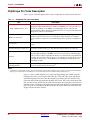
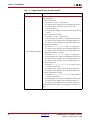
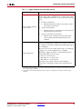
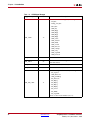
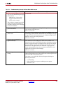
The MGT/BERT Settings panel contains a table that is made up of one or more vertical
columns and horizontal rows. Each column represents a specific active GTP/GTX
transceiver channel. Each row represents a specific GTP/GTX or
GTP_DUAL/GTX_DUAL control or status setting.
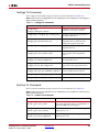
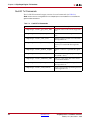
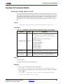
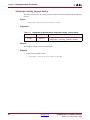
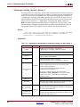
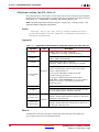
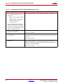
MGT Settings
The MGT Settings control and status indicators are related to the various settings for a
particular GTP_DUAL/GTX_DUAL channel.
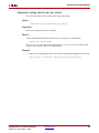
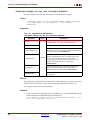
The MGT Alias setting is initially set to the MGT and channel number of the GTP/GTX
transceiver channel, but can be changed by selecting the field and typing in a new value.
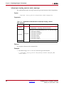
The GTP_DUAL/GTX_DUAL Location setting denotes the X/Y coordinate of the
GTP_DUAL/GTX_DUAL in the device.
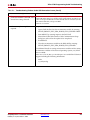
The MGT Link Status indicator is displays the status of the link detection logic that is
connected to the receiver of a particular GTP/GTX transceiver channel. The valid states of
this status indicator are LOCKED (green) and NOT LOCKED (red).
The REFCLKOUT PLL Status indicator shows the lock status of the PLL that is connected
to the REFCLKOUT port of the GTP_DUAL/GTX_DUAL. The valid states of this status
indicator are LOCKED (green) or NOT LOCKED (red).
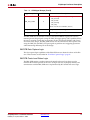
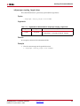
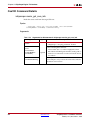
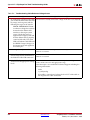
The Loopback Mode setting is used to control the loopback mode of a particular
GTP/GTX transceiver channel. The valid choices for loopback mode are:
•
None: No feedback path is used.
•
Near-End PCS: The circuit is wholly contained within the near-end GTP/GTX
transceiver channel. It starts at the TX fabric interface, passes through the PCS, and
returns immediately to the RX fabric interface without ever passing through the PMA
side of the GTP/GTX transceiver channel.
•
Near-End PMA: The circuit is wholly contained within the near-end GTP/GTX
transceiver channel. It starts at the TX fabric interface, passes through the PCS,
through the PMA, back through the PCS, and returns to the RX fabric interface.
•
Far-End PMA: The circuit originates and ends at some external channel endpoint (for
example, a piece of test equipment or another device) but passes through the part of
the GTP/GTX transceiver channel. For this GTP/GTX transceiver loopback mode, the
signal comes into the RX pins, passes through the PMA circuitry, and returns
immediately to the TX pins.
•
Far-End PCS: The circuit originates and ends at some external channel endpoint (for
example, a piece of test equipment or another device) but passes through part of the
GTP/GTX transceiver channel. For this GTP/GTX transceiver loopback mode, the
signal comes into the RX pins, passes through the PMA, through the PCS, back
through the PMA, and returns to the TX pins.
•
Far-End Fabric: The circuit originates and ends at some external channel endpoint (for
example, a piece of test equipment or another device) but passes through the entire
GTP/GTX transceiver channel and related fabric logic. For this GTP/GTX transceiver
loopback mode, the signal comes into the RX pins, passes through the PMA and PCS,
through a shallow fabric-based FIFO, back through the PCS and PMA, and finally
returns to the TX pins.
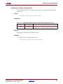
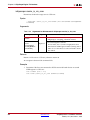
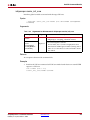
The Channel Reset button resets the GTP/GTX transceiver channel by clearing and
resetting all internal PMA and PCS circuitry as well as the related fabric interfaces.
142
www.xilinx.com
ChipScope Pro 11.4 Software and Cores
UG029 (v11.4) December 2, 2009