1
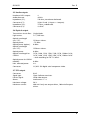
Flashlink User Manual
AV-MUX
Digital Audio (De-)embedder
network-electronics.com
Rev. 9
AV-MUX
Rev. 9
Network Electronics ASA
Thorøya
P.O. Box 1020
Sandefjord, Norway
Phone: +47 33 48 99 99
Fax: +47 33 48 99 98
E-mail: [email protected]
www.network-electronics.com
Service Phone: +47 90 60 99 99
Revision history
Current revision of this document is the uppermost in the table below.
Revision Replaces
Date
9
8
7
6
8
7
6
5
2007-10-23
2007-10-05
06/02/06
16/06/05
5
4
15/11/02
4
3
19/06/02
3
2
14/12/01
2
1
E
D
C
B
A
1
E
D
C
B
A
29/11/01
15/10/01
25/09/01
11/09/01
26/07/01
Change description
New front page and removed old logo.
Added Materials Declaration and EFUP
Updated CWDM laser options.
Added CWDM information.
Block diagram. Improved configuration
descriptions.
DIP switch and Gyda figures. C2 backplane
Change default. Disembedding now removes
audio.
DIP switch descriptions
Power limitations, de-embed not disembed.
Cascade Gyda command, Add-drop option.
Re-corrected audio connections. Gyda interface.
Corrected the audio connections
More limitations.
Preliminary version. Pre production run.
2
AV-MUX
Rev. 9
Contents
Revision history............................................................................... 2
1 Product overview......................................................................... 5
1.1 Signal flow...................................................................................................6
1.2 Product versions ..........................................................................................6
2 Specifications .............................................................................. 7
2.1 General........................................................................................................7
2.2 Video input..................................................................................................7
2.3 Audio inputs ................................................................................................7
2.4 SDI output...................................................................................................7
2.5 Audio outputs..............................................................................................8
2.6 Optical output.............................................................................................8
2.7 GPI output...................................................................................................8
3 Limitations................................................................................... 9
3.1 Power ..........................................................................................................9
3.2 Embedding..................................................................................................9
3.3 De-embedding ............................................................................................9
4 Configuration ............................................................................ 10
4.1 DIP switches ..............................................................................................10
4.1.1 Override
10
4.1.2 A Embed
10
4.1.3 A G3
10
4.1.4 B Embed
10
4.1.5 B G4
11
4.1.6 Unmarked or A&B Gn
11
4.1.7 Prog M
11
4.1.8 Prog S
11
4.2 Embedded audio removal..........................................................................12
4.3 Sample rate converters ..............................................................................12
4.4 Monitoring the status with GYDA-SC.........................................................12
5 Connector module .................................................................... 15
5.1 AV-MUX-C1...............................................................................................15
5.2 Mounting the connector module ..............................................................15
5.3 AV-MUX-C2...............................................................................................16
5.4 Audio connections.....................................................................................16
6 Module status............................................................................ 18
6.1 GPI – Module status outputs......................................................................18
6.2 Front panel – Status monitoring ................................................................19
7 Laser safety precautions ............................................................. 20
3
AV-MUX
Rev. 9
®
General environmental requirements for flashlink equipment ...... 21
Certificate of Conformity .............................................................. 22
Product Warranty ......................................................................... 23
Materials declaration and recycling information............................ 24
Materials declaration .................................................................... 24
Environmentally-friendly use period.............................................. 24
Recycling information................................................................... 25
4
AV-MUX
Rev. 9
1 Product overview
The AV-MUX card is an eight audio channel, digital audio embedder and de®
embedder card for serial digital video. It is one of the Flashlink series of
modules, providing a compact and cost effective solution for the transport of
digital video and audio over single mode optical fibre.
The card has a serial digital video input and a serial digital video output. There
is an optional optical output with a choice of lasers with –7.5 dBm and 0 dBm
output powers, and wavelengths of 1310 nm and 1550 nm. This corresponds
®
to the flashlink range of SDI-EO, electrical to optical converter cards.
AV-MUX-C1xxx also supports CWDM wavelengths according to ITU-T G.694
from 1270±6nm up to 1610±6nm.
The AV-MUX card has four AES inputs and four AES outputs. The card may be
used both as an embedder and a de-embedder. The card has two audio
embedding processors, which can each process a group of four audio
channels. This means the card can embed eight channels, de-embed eight
channels or de-embed four channels and embed four channels.
Inputs
Outputs
SRC
AES 4
AES 4
SRC
AES 3
AES 3
SRC
AES 2
AES 2
SRC
AES 1
AES 1
Laser
EDH
processor
Embedding
processor
A
Embedding
processor
B
SDI receiver
Serialiser
SDI transmitter
Figure 1: AV-MUX block diagram.
5
AV-MUX
Rev. 9
1.1 Signal flow
The digital video passes through the receiver and the EDH information is
processed in the de-serialiser. It then is passed to the two embedding
processors, one after the other. The video signal is then re-serialised and sent
to the electrical and optical outputs.
The AES digital audio inputs 1 and 2 go to the first processor and inputs 3 and
4 go to the second processor. Similarly the audio outputs from the first
processor go to AES outputs 1 and 2 while the audio outputs from the second
processor go to AES outputs 3 and 4. Sample rate converters are automatically
switched into the signal flow if the AES input audio is not locked to the video
signal. The sample rate converters are always switched on or off, for both of
the audio inputs going to an embedding processor. i.e.AES input pair 1 and 2
(or 3 and 4) are switched together. The AES audio outputs are on when the
corresponding inputs are present. When the corresponding processor is used
as an embedder, the sample rate converted input signal is present on the
outputs.
1.2 Product versions
AV-MUX-C1xxx is available in the following versions, all with DFB lasers:
Part No.
Wavelength
Part No.
Wavelength
AV-MUX-C1270 1270±6nm 0dBm
AV-MUX-C1470 1470±6nm 0dBm
AV-MUX-C1290 1290±6nm 0dBm
AV-MUX-C1490 1490±6nm 0dBm
AV-MUX-C1310 1310±6nm 0dBm
AV-MUX-C1510 1510±6nm 0dBm
AV-MUX-C1330 1330±6nm 0dBm
AV-MUX-C1530 1530±6nm 0dBm
AV-MUX-C1350 1350±6nm 0dBm
AV-MUX-C1550 1550±6nm 0dBm
AV-MUX-C1370 1370±6nm 0dBm
AV-MUX-C1570 1570±6nm 0dBm
AV-MUX-C1390 1390±6nm 0dBm
AV-MUX-C1590 1590±6nm 0dBm
AV-MUX-C1410 1410±6nm 0dBm
AV-MUX-C1610 1610±6nm 0dBm
6
AV-MUX
Rev. 9
2 Specifications
2.1 General
Power:
Control:
Monitoring:
EDH processing:
Embedding level
(SMPTE S272M):
+5V DC / 1A.
DIP switches or Control system module.
Front panel LED’s, GPI and control system module.
Full. Received flags are updated, new CRCs are calculated.
C - Synchronous audio at 48 kHz and extended data
packets (24 bit).
2.2 Video input
Video data rate:
Video frame rate:
Equalisation:
Impedance:
Return loss:
Signal level:
Connector:
270 Mbps or 540 Mbps.
50 Hz or 60 Hz.
Automatic up to 35dB.
75 ohm.
>15dB @270MHz.
Nom. 800mV.
BNC
2.3 Audio inputs
Number of AES inputs:
Audio data rate:
Impedance (C1):
Connector (C1)
Impedance (C2):
Connector (C2)
Embedded audio word length:
Embedded audio channel status:
4
16 kHz to 144 kHz, converted to 48 kHz if necessary.
110 ohm, transformer balanced.
25 pin D-sub. (4 Inputs + 4 outputs).
75 ohm, unbalanced.
4 x BNC.
24 bits.
As received when synchronous. Otherwise fixed.
2.4 SDI output
Number of SDI outputs:
Rise-/fall time:
Impedance:
Return loss:
Signal level:
Connector:
1
Typ. 650ps.
75 ohm.
>15dB @270MHz.
Nom. 800mV.
BNC
7
AV-MUX
Rev. 9
2.5 Audio outputs
Number of AES outputs:
Audio data rate:
Impedance (C1):
Connector (C1)
Impedance (C2):
Connector (C2)
4
48 kHz.
110 ohm, transformer balanced.
25 pin D-sub. (4 Inputs + 4 outputs).
75 ohm, unbalanced.
4 x BNC.
2.6 Optical output
Transmission circuit fiber:
Light source:
Optical wavelength
(ver. 13T):
Optical power:
Optical power (option):
Optical wavelength
(ver. 15T):
Optical power:
Optical wavelength for
CWDM:
Optical power for CWDM
modules:
Max. reflected power:
Connector:
Single Mode.
F-P / DFB laser.
1310nm±40nm.
-7.5 dBm.
0 dBm.
1550nm±40nm.
0 dBm.
1270, 1290, 1310, 1330, 1350, 1370, 1390 or 1410,
1470, 1490, 1510, 1530, 1550, 1570, 1590 or 1610
±6nm according to ITU-T G.694.2
0 dBm
4%.
SC/UPC SDI digital serial component video.
2.7 GPI output
Connector:
Signal type:
Positive signal:
Alarms:
Maximum voltage:
Maximum current:
RJ45.
Open Collector transistor.
Valid video output.
Audio errors 1 – 4.
50 V.
400 mA if only one output driven, 100 mA all outputs
driven.
8
AV-MUX
Rev. 9
3 Limitations
3.1 Power
The AV-MUX cards consume about 1A of 5V power. This means that they
need some breathing space in order to keep cool. The cards should always
have free slots on both sides and must not be placed in slot position 1 without
forced cooling. This ‘waste of space’ also prevents the overloading of the
power supply.
3.2 Embedding
The embedder processors only work in one mode at a time so that they do
not detect the presence of incorrectly embedded audio when embedding.
The embedding processors will not detect existing audio groups with the
same number in the incoming video. This may result in audio becoming
irretrievable or corrupt.
The AES Channel status and user bits are only transferred if the audio is
synchronous to video. This means that asynchronous audio with, for example,
pre-emphasis will lose that information.
3.3 De-embedding
The de-embedders will only work well with audio data that has been
embedded at 48 kHz, synchronous to the video signal. They will work with
equipment conforming to SMPTE S272M A or C.
The AES Channel status is regenerated in the card and no bits are carried from
the received embedded audio signal. The AV-DMUX card will correctly decode
the Channel Status bits.
The Full Field CRC words are not updated when de-embedding. The EDH
packet in the SDI output is still valid after the audio group is removed but a
flag is set to indicate an invalid Full Field CRC. If the audio is allowed to remain
in the SDI signal, the EDH output packet will be correct.
9
AV-MUX
Rev. 9
4 Configuration
Digital video may have up to four groups of four audio channels. An audio
group has four audio channels. Each audio group contains two AES stereo
audio signals. Each embedding processor works with a single audio group, so
the AV-MUX card can work with two audio groups which are eight mono
audio channels. The first embedding processor normally processes either
group one, or group three. The second processor normally processes either
group two, or group four. Embedded audio in video from digital VTRs is
usually embedded in group 1. Embedding with group 1 with the AV-MUX is
only used if the original audio is absent, or to be replaced.
NOTE! The AV-MUX removes all existing audio when embedding on group 1.
Embedding on other audio groups appends the new group to existing
embedded audio.
4.1 DIP switches
The configuration of the card sets a number of parameters:
- The operational mode for each of the embedding processors, embedding
or de-embedding.
- The audio group numbers being processed for each embedding processor.
- Whether the audio is removed.
4.1.1 Override
The card is normally configured with switches on the front of the card and
additional options may be controlled with the GYDA monitoring/ control card.
The microcontroller on the AV-MUX card reads the DIP switches If the card
configuration is changed with GYDA, the new configuration is stored on the
card. The OVERRIDE switch must be in the off position if these changes are
not be lost.
4.1.2 A Embed
This switch controls the audio direction in embedding processor A, to or from
the video. Embedding processor A embeds audio when the switch is on and
de-embeds audio when the switch is off.
4.1.3 A G3
This switch sets the audio group number for embedding processor A.
Embedding processor A uses group 3 when the switch is on but uses group 1
if the switch is off.
NOTE! When the first processor A is configured to embed audio on group
one, all existing ancillary data will be removed. The other embedding
configurations will add new audio groups to the video signal.
4.1.4 B Embed
This switch controls the audio direction in embedding processor B, to or from
the video. Embedding processor B embeds audio when the switch is on and
de-embeds audio when the switch is off.
10
AV-MUX
Rev. 9
4.1.5 B G4
This switch sets the audio group number for embedding processor B.
Embedding processor B uses group 4 when the switch is on but uses group 2
if the switch is off.
4.1.6 Unmarked or A&B Gn
This DIP switch may be used to assign the same group number to both
embedder processors. This would be useful if the card is used as an add/ drop
node, or for confidence monitoring. The group number is then set by the
combination of the two group switches, as shown in the following table.
Group Switch A G3 Switch B G4
1
Off
Off
2
Off
On
3
Off
On
4
On
On
Group assignment when both embedding processors use the same group.
4.1.7 Prog M
This switch is only used when programming the master microcontroller and
must be switched off.
4.1.8 Prog S
This switch is only used when programming the slave microcontroller and
must be switched off.
Configuration From DIPs
De-embed A
A Group 1
De-embed B
B Group 2
A and B different groups
Off
Off
Figure 2: AV-MUX DIP switches configured to de-embed groups 1 and 2.
11
AV-MUX
Rev. 9
4.2 Embedded audio removal
De-embedding does not change the active video, but the audio signals are
normally removed. The EDH packet flags are always updated and SDI format
errors are corrected. The Full Field CRC words are not updated when deembedding and are therefore incorrect after the audio group is removed. A
flag is set in the EDH packet to indicate this to downstream equipment to
avoid the false indication of transmission errors.
This default behaviour has been adopted because many 8 bit D/A converters
will not tolerate two embedded audio groups. Some of these converters will
tolerate one 20 bit audio group but no more. The intolerance is in the actual
D/A converter chip.
The embedded audio group may remain in the SDI after de-embedding if
necessary. This configuration may only be set with a command from the
GYDA controller but the OVERRIDE DIP switch must be in the off position to
keep the configuration.
4.3 Sample rate converters
The sample rate converters (SRCs) on each of the AES inputs are only used
when the audio is found to be asynchronous with the incoming video signal.
This is intended as a fail-safe mechanism that will not be in use in most
broadcast installations where the audio is isosynchronous with the video. This
strategy has a couple of trade-offs. If the audio is 48 kHz but not locked to the
video, it may take many seconds before the SRCs are switched on. This is
because the AV-MUX card waits until three samples have been lost or skipped
before switching. The other caveat (problem) is connected to the fact that the
embedding processor will only accept the same sort of audio on it’s inputs.
The SRCs must be switched into both of the AES signals going to the
embedding processor. In certain circumstances, the card has to make a brutal
decision. If an isosynchronous signal is presented to one of the inputs to the
embedding processor, the SRCs will not be used. If a second signal is then
applied to the other input of the pair, the SRCs will be switched into both
inputs. This causes an short interruption to the first signal. This is the only
situation where existing audio is disturbed by the other input. The SRCs
remain in use, even if the asynchronous input is disconnected. SRCs are
removed when both of the AES inputs are disconnected. The SRCs can also be
removed from the Gyda user interface. Switching of signals when SRCs are in
use will not cause any interruption of the other signal.
4.4 Monitoring the status with GYDA-SC
The GYDA-SC controller card receives information about the configuration
and the operating status of the card. The displayed information includes: - Power voltage
- Video signal margin
- Video format
- EDH flags and error counter
- Embedder processor configuration
- Embedder processing errors
- Audio I/O PLL status and if SRCs are in use
12
AV-MUX
Rev. 9
Figure 3: AV-MUX information page in GYDA-SC.
Figure 4: AV-MUX configuration page in GYDA-SC.
Gyda can also control a few parameters and these are:
13
AV-MUX
Rev. 9
- Switch Laser on or off
- Switch SRC 1 & 2 on or off
- Switch SRC 3 & 4 on or off
- Remove audio group after de-embedding or not.
The control buttons only appear on the page when they are relevant.
14
AV-MUX
Rev. 9
5 Connector module
5.1 AV-MUX-C1
Figure 5: Connector module AV-MUX-C1 for AV-MUX.
5.2 Mounting the connector module
The details of how the connector module is mounted, is found in the user
manual for the sub-rack frame FR-2RU-10-2.
This manual is also available from our web site:
http://www.network-electronics.com/.
15
AV-MUX
Rev. 9
5.3 AV-MUX-C2
Figure 6: Connector module AV-MUX-C2 for AV-MUX.
5.4 Audio connections
The C1 connector card has a D-sub 25 pin connector for all eight audio
signals. The pin configuration is similar to the TASCAM DA-88 connector
except that both the input and output signals are on the same connector. The
configuration is shown in the figure below. AES 1 and 2 come from deembedder A. AES 3 and 4 come from de-embedder B.
The C2 connector card has BNC connections for AES-3ID 75 unbalanced
signals. The backplane is designed for four outputs and four inputs. Only the
signals on the connectors marked as outputs are compliant with the AES-3ID
specification.
16
AV-MUX
Rev. 9
13 12 11 10 9
8
7
6
5
4
Inputs
Inputs
3
2
1
1
2
3
4
1
2
3
4
25 24 23 22 21 20 19 18 17 16 15 14
Outputs
utputs
AES
AES
AES
AES
AES
AES
AES
AES
Gnd.
Gnd.
Cold
Hot
Gnd.
Cold
Hot
Gnd.
Cold
Hot
Gnd.
Cold
Hot
Gnd.
Cold
Hot
Gnd.
Cold
Hot
Gnd.
Cold
Hot
Gnd.
Cold
Hot
Figure 7: Audio connector configuration for AV-MUX.
17
AV-MUX
Rev. 9
6 Module status
The status of the module can be monitored in three ways.
1. GYDA-SC System Controller (optional).
2. GPI at the rear of the sub-rack.
3. LED’s at the front of the sub-rack.
Of these three, the GPI and the LED’s are mounted on the module itself,
whereas the GYDA-SC System Controller is a separate module giving detailed
information on the card status. The functions of the GPI and the LED’s are
described in sections 6.1 and 6.2. The GYDA controller is described in a
separate user manual.
6.1 GPI – Module status outputs
These outputs can be used for wiring up alarms for third party control
systems. The GPI outputs are open collector outputs, sinking to ground when
an alarm is triggered. The GPI connector is shown in figure below.
Signal
AV-MUX module GPI pinning:
Name
Pin # Mode
Valid Video Valid video is output
1
Open Collector
AES1 Error
AES 1 receiver error
2
Open Collector
AES2 Error
AES 2 receiver error
3
Open Collector
AES3 Error
AES 3 receiver error
4
Open Collector
AES4 Error
AES 4 receiver error
5
Open Collector
Ground
0 V pin
8
0V.
Figure 8: GPI output.
Electrical Maximums for GPI outputs
Max current: 100mA
Max voltage: 50V
18
AV-MUX
Rev. 9
6.2 Front panel – Status monitoring
The status of the module can be easily monitored visually by the LED’s at the
front of the module. The LED’s are visible through the front panel as shown in
the figure below.
Power
SDI / Laser
AES 1 & 2
AES 3 & 4
Figure 9: Front panel indicators for the AV-MUX (text not printed on the front panel).
The AV-MUX has 4 LED’s. The colours of each of the LED’s have different
meanings as shown in the table below:
Diode \ State
Red LED
Orange LED
Green LED
No light
Power
PTC fuse has been
triggered - remove
the module.
Video signal
absent.
No AES signals
present
No AES signals
present
N/A
Module power is
OK
Module has no
power
Laser failure.
Video input signal
Present
Both AES signals
present
Both AES signals
present
SDI / Laser
AES 1 & 2
AES 3 & 4
One AES signal
present
One AES signal
present
If all of the lower three LED are orange, then the card is not in operation.
Check that the two lower DIP switches are in the OFF position. If the lower
three LEDs are still orange after power-up, the card should be replaced.
Contact Network Support.
19
AV-MUX
Rev. 9
7 Laser safety precautions
Guidelines to limit hazards from laser exposure.
All the available EO units in the flashlink® range include a laser.
Therefore this note on laser safety should be read thoroughly.
The lasers emit light at 1310 nm or 1550 nm. This means that the human eye
cannot see the beam, and the blink reflex cannot protect the eye. (The human
eye can see light between 400 nm to 700 nm).
A laser beam can be harmful to the human eye (depending on laser power
and exposure time), therefore:
Note!
BE CAREFUL WHEN CONNECTING / DISCONNECTING FIBER
PIGTAILS (ENDS).
NEVER LOOK DIRECTLY INTO THE PIGTAIL OF THE
LASER/FIBER.
NEVER USE MICROSCOPES, MAGNIFYING GLASSES OR EYE
LOUPES TO LOOK INTO A FIBER END.
USE LASER SAFETY GOGGLES BLOCKING LIGHT AT
1310 nm AND AT 1550 nm.
Instruments exist to verify light output power: Power meters, IR-cards etc.
Flashlink® features:
All the laser module cards in the flashlink® product range, are Class 1
laser products according to IEC 825-1 1993, and class I according to
21 CFR 1040.10 when used in normal operation.
More details can be found in the user manual for the FR-2RU-10-2 frame.
1
Maximum output power : 5 mW.
Operating wavelengths: > 1270 nm.
< 5mW
>1270nm
1
Max power is for safety analysis only and does not represent device performance.
20
AV-MUX
Rev. 9
®
General environmental requirements for flashlink equipment
1. The equipment will meet the guaranteed performance specification under the
following environmental conditions:
- Operating room temperature range:
0°C to 50°C
- Operating relative humidity range:
< 90% (non-condensing)
2. The equipment will operate without damage under the following environmental
conditions:
- Temperature range:
-10°C to 55°C
- Relative humidity range:
< 95% (non-condensing)
3. Electromagnetic compatibility conditions:
- Emissions:
EN 55103-1 (Directive 89/336/EEC)
- Immunity:
EN 55103-2 (Directive 89/336/EEC)
21
AV-MUX
Rev. 9
Certificate of Conformity
Network Electronics ASA
N-3204 Sandefjord
Norway
Company Registration Number:
NO 976 584 201 MVA
Declares under sole responsibility that the product:
Product Name:
AV-MUX
Product Description:
Digital Audio (De-)Embedder
To which this declaration relates are of Norwegian origin and are in conformity with
the following standards:
EN 55103-1: 1996
Generic Emissions Standard
EN 55103-2: 1996
Generic Immunity Standard
22
AV-MUX
Rev. 9
Product Warranty
The warranty terms and conditions for the product(s) covered by this manual follow the
General Sales Conditions by Network Electronics ASA. These conditions are available
on the company web site of Network Electronics ASA:
www.network-electronics.com
23
AV-MUX
Rev. 9
Materials declaration and recycling information
Materials declaration
For product sold into China after 1st March 2007, we comply with the “Administrative
Measure on the Control of Pollution by Electronic Information Products”. In the first
stage of this legislation, content of six hazardous materials has to be declared. The table
below shows the required information.
Toxic or hazardous substances and elements
組成名稱
Part Name
AV-MUX
鉛
汞
镉
六价铬
多溴联苯
多溴二苯醚
Lead Mercury Cadmium Hexavalent Polybrominated Polybrominated
(Pb)
(Hg)
(Cd)
Chromium
biphenyls
diphenyl ethers
(Cr(VI))
(PBB)
(PBDE)
X
O
O
O
O
O
O: Indicates that this toxic or hazardous substance contained in all of the homogeneous materials for
this part is below the limit requirement in SJ/T11363-2006.
X: Indicates that this toxic or hazardous substance contained in at least one of the homogeneous
materials used for this part is above the limit requirement in SJ/T11363-2006.
Environmentally-friendly use period
The manual must include a statement of the “environmentally friendly use period”.
This is defined as the period of normal use before any hazardous material is released to
the environment. The guidance on how the EFUP is to be calculated is not finalised at
the time of writing. See
http://www.aeanet.org/GovernmentAffairs/qfLeOpAaZXaMxqGjSFbEidSdPNtpT.pdf
for an unofficial translation of the draft guidance. For our own products, Network
Electronics has chosen to use the 50 year figure recommended in this draft regulation.
Network Electronics suggests the following statement on An “Environmentally Friendly
Use Period” (EFUP) setting out normal use:
EFUP is the time the product can be used in normal service life without leaking the hazardous materials.
We expect the normal use environment to be in an equipment room at controlled temperature range
(0ºC - 40ºC) with moderate humidity (< 90%, non-condensing) and clean air, not subject to vibration or
shock.
Further, a statement on any hazardous material content, for instance, for a product that
uses some tin/lead solders:
Where a product contains potentially hazardous materials, this is indicated on the product by the
appropriate symbol containing the EFUP. The hazardous material content is limited to lead (Pb) in some
solders. This is extremely stable in normal use and the EFUP is taken as 50 years, by comparison with the
EFUP given for Digital Exchange/Switching Platform in equipment in Appendix A of “General Rule of
Environment-Friendly Use Period of Electronic Information Products”. This is indicated by the product
marking:
50
24
AV-MUX
Rev. 9
It is assumed that while the product is in normal use, any batteries associated with real-time clocks or
battery-backed RAM will be replaced at the regular intervals.
The EFUP relates only to the environmental impact of the product in normal use, it does not imply
that the product will continue to be supported for 50 years.
Recycling information
Network Electronics provides assistance to customers and recyclers through our web
site http://www.network-electronics.com. Please contact Network Electronics’
Customer Support for assistance with recycling if this site does not show the
information you require.
Where it is not possible to return the product to Network Electronics or its agents for
recycling, the following general information may be of assistance:
Before attempting disassembly, ensure the product is completely disconnected from
power and signal connections.
All major parts are marked or labelled to show their material content.
Depending on the date of manufacture, this product may contain lead in solder.
Some circuit boards may contain battery-backed memory devices.
25