1
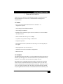
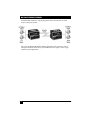
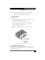
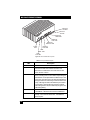
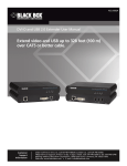
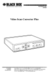
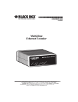
BLACK BOX
®
NETWORK SERVICES
DECEMBER 2005
LB200A
Multi-Rate
Ethernet Extender
et Extender
LINK
X
R
O
L
FD
x
10
0M
TX
nk
C
Li
L
O
nk
Q
Li
w
er
Multi-Rate Ethern
Po
®
Ethernet
CUSTOMER Order toll-free in the U.S. 24 hours, 7 A.M. Monday to midnight Friday: 877-877-BBOX
SUPPORT FREE technical support, 24 hours a day, 7 days a week: Call 724-746-5500 or fax 724-746-0746
INFORMATION Mail order: Black Box Corporation, 1000 Park Drive, Lawrence, PA 15055-1018
Web site: www.blackbox.com • E-mail: [email protected]
MULTI-RATE ETHERNET EXTENDER
CE NOTICE
The CE symbol on your Black Box equipment indicates that it is in compliance
with the Electromagnetic Compatibility (EMC) directive and the Low Voltage
Directive (LVD) of the European Union (EU). A Certificate of Compliance is
available by contacting Technical Support.
RADIO AND TV INTERFERENCE
The Multi-Rate Ethernet Extender generates and uses radio frequency energy,
and if not installed and used properly-that is, in strict accordance with the manufacturer’s instructions-may cause interference to radio and television reception.
The Multi-Rate Ethernet Extender has been tested and found to comply with the
limits for a Class A computing device in accordance with specifications in Subpart B of Part 15 of FCC rules, which are designed to provide reasonable protection from such interference in a commercial installation. However, there is no
guarantee that interference will not occur in a particular installation. If the Ethernet Extender does cause interference to radio or television reception, which can
be determined by disconnecting the unit, the user is encouraged to try to correct
the interference by one or more of the following measures: moving the computing equipment away from the receiver, re-orienting the receiving antenna and/or
plugging the receiving equipment into a different AC outlet (such that the computing equipment and receiver are on different branches).
2
MULTI-RATE ETHERNET EXTENDER
FCC PART 68
The LB200A is not intended to be connected to the public telephone network.
Caution
TRADEMARKS USED IN THIS MANUAL
All applied-for and registered trademarks are the property of their respective owners.
NORMAS OFICIALES MEXICANAS (NOM) ELECTRICAL SAFETY STATEMENT
Instrucciones De Seguridad
1. Todas las instrucciones de seguridad y operación deberán ser leídas antes
de que el aparato eléctrico sea operado.
2. Las instrucciones de seguridad y operación deberán ser guardadas para referencia futura.
3. Todas las advertencias en el aparato eléctrico y en sus instrucciones de
operación deben ser respetadas.
4. Todas las instrucciones de operación y uso deben ser seguidas.
5. El aparato eléctrico no deberá ser usado cerca del agua—por ejemplo, cerca
de la tina de baño, lavabo, sótano mojado o cerca de una alberca, etc.
6. El aparato eléctrico debe ser usado únicamente con carritos o pedestales
que sean recomendados por el fabricante.
7. El aparato eléctrico debe ser montado a la pared o al techo sólo como sea
recomendado por el fabricante.
8. Servicio—El usuario no debe intentar dar servicio al equipo eléctrico más
allá a lo descrito en las instrucciones de operación. Todo otro servicio
deberá ser referido a personal de servicio calificado.
9. El aparato eléctrico debe ser situado de tal manera que su posición no interfiera su uso. La colocación del aparato eléctrico sobre una cama, sofá, alfombra
o superficie similar puede bloquea la ventilación, no se debe colocar en libreros o gabinetes que impidan el flujo de aire por los orificios de ventilación.
10. El equipo eléctrico deber ser situado fuera del alcance de fuentes de calor
como radiadores, registros de calor, estufas u otros aparatos (incluyendo
amplificadores) que producen calor.
3
MULTI-RATE ETHERNET EXTENDER
11. El aparato eléctrico deberá ser connectado a una fuente de poder sólo del tipo
descrito en el instructivo de operación, o como se indique en el aparato.
12. Precaución debe ser tomada de tal manera que la tierra fisica y la polarización
del equipo no sea eliminada.
13. Los cables de la fuente de poder deben ser guiados de tal manera que no sean
pisados ni pellizcados por objetos colocados sobre o contra ellos, poniendo
particular atención a los contactos y receptáculos donde salen del aparato.
14. El equipo eléctrico debe ser limpiado únicamente de acuerdo a las recomendaciones del fabricante.
15. En caso de existir, una antena externa deberá ser localizada lejos de las lineas
de energia.
16. El cable de corriente deberá ser desconectado del cuando el equipo no sea
usado por un largo periodo de tiempo.
17. Cuidado debe ser tomado de tal manera que objectos liquidos no sean derramados sobre la cubierta u orificios de ventilación.
18. Servicio por personal calificado deberá ser provisto cuando:
A. El cable de poder o el contacto ha sido dañado; u
B. Objectos han caído o líquido ha sido derramado dentro del aparato; o
C. El aparato ha sido expuesto a la lluvia; o
D. El aparato parece no operar normalmente o muestra un cambio en su
desempeño; o
E. El aparato ha sido tirado o su cubierta ha sido dañada.
4
MULTI-RATE ETHERNET EXTENDER
CONTENTS
CE Notice .................................................................................................... 2
Radio and TV Interference .......................................................................... 2
FCC Part 68 ................................................................................................. 3
Trademarks Used In This Manual ............................................................... 3
Normas Oficiales Mexicanas (NOM) Electrical Safety Statement ............. 3
1.
General Information ....................................................................................7
1.1 Features ...............................................................................................7
1.2 Description ......................................................................................... 7
2.
Installation ................................................................................................... 9
2.1 Installing the LB200A ........................................................................9
2.2 Connecting the Twisted-Pair Line Interface....................................... 9
2.3 Connecting the 10/100Base-T Ethernet Interface ............................ 11
2.3.1 Connecting the 10/100Base-T Ethernet Port to a Hub .......... 12
2.3.2 Connecting the 10/100Base-T Ethernet Port to a PC (DTE). 12
2.4 Connecting Power ............................................................................ 12
3.
Configuration............................................................................................. 14
3.1 Configuring DIP Switch S1 ..............................................................15
3.1.1 Switch S1-1: Ethernet Auto Sense .........................................15
3.1.2 Switches S1-2 and S1-4: Line Rate ....................................... 16
4.
Operation ................................................................................................... 17
4.1 Power Up ..........................................................................................17
4.2 Front Panel LED Status Monitors .................................................... 17
A.
Specifications ............................................................................................ 19
A.1 LAN Connection ..............................................................................19
A.2 Transmission Line ............................................................................19
A.3 Multi-Rate Ethernet Extender Line Rate ..........................................19
A.4 Multi-Rate Ethernet Extender Distance ............................................19
A.5 Line Surge Suppressor ......................................................................19
A.6 LED Status Indicators .......................................................................19
A.7 Power Supply ....................................................................................19
A.8 Temperature Range ..........................................................................20
5
MULTI-RATE ETHERNET EXTENDER
A.9 Humidity ...........................................................................................20
A.10 Dimensions .......................................................................................20
B.
Multi-Rate Ethernet Extender Interface Pin Assignment .......................... 21
B.1 10/100Base-T Interface ....................................................................21
B.2 Line Interface ....................................................................................21
4.2.3 Terminal Block ...................................................................... 21
C.
6
Distance Chart, Based on 24 AWG (0.5 mm) ........................................... 22
MULTI-RATE ETHERNET EXTENDER
1. General Information
Thank you for your purchase of this Black Box product. If any questions arise
during installation or use of the unit, contact Black Box Tech Support at
(724) 746-5500.
1.1 Features
• Easy to install standalone Multi-Rate Ethernet Extenders—no
configuration required
• Auto-sensing full or half-duplex Ethernet
• Auto-sensing 10/100Base-T
• Extends network connections up to 6,652 ft. (2.03 km) over 2-wire 24-AWG
unconditioned lines
• Switch selectable line rates up to 16.67 Mbps
• 7 symmetric or asymmetric settings via DIP switch
• Transparent operation
• LED indicators for Power, Ethernet Link & Activity, Line Link & Quality of
Line (QoL)
• Surge suppression up to 20 kA (8/20 µs)
• Available in rack-mount or standalone configurations
• Made in the USA
1.2 Description
The Multi-Rate Ethernet Extender/L (Local) and Multi-Rate Ethernet Extender/R
(Remote) provide high speed LAN connections between peered Ethernet LANs,
remote PC’s, or any other network enabled 10/100Base-T device.
Operating in pairs, a Multi-Rate Ethernet Extender/L located at one end of the
LAN extension and an Multi-Rate Ethernet Extender/R at the other end, these
units can automatically forward LAN broadcasts, multicasts, and frames across a
2-wire voice-grade twisted-pair link. The data is passed transparently (unmodified) through the Ethernet Extenders. The Ethernet Extenders automatically add
7
MULTI-RATE ETHERNET EXTENDER
and delete MAC addresses, only passing packets across the link that are meant
for the remote peered LAN.
Figure 1. Typical application
The Local and Remote Multi-Rate Ethernet Extenders work together to create a
transparent extension between two peered Ethernet LANs. Figure 1 shows a typical point-to-point application.
8
MULTI-RATE ETHERNET EXTENDER
2. Installation
Because the LB200A requires no configuration, it can be installed quickly.
Note
If asymmetric transmission or line rates other than 12.5 Mbps are
required, refer to section 3., “Configuration” on page 14.
2.1 Installing the LB200A
Do the following:
1. Connect the line interface between the units (refer to section 2.2, “Connecting the Twisted-Pair Line Interface” on page 9)
Note
See Figure 2 for the standalone unit’s rear panel arrangements.
2. Connect the Ethernet interface (refer to section 2.3, “Connecting the
10/100Base-T Ethernet Interface” on page 11).
3. Connect the power plug (refer to section 2.4, “Connecting Power” on
page 12).
K
LIN
Ethernet
port
LINK twisted-pair
RJ-45 interface
LINK twisted-pair
terminal block
interface
Figure 2. Multi-Rate Ethernet Extender standalone rear panel
2.2 Connecting the Twisted-Pair Line Interface
The Multi-Rate Ethernet Extender supports communication between two peer
Ethernet LAN sites over a distance of up to 6,652 ft. (2.03 km) over 24 AWG
(0.5 mm) twisted-pair wire.
9
MULTI-RATE ETHERNET EXTENDER
Note
Actual distance and link performance may vary depending on the environment and type/gauge of wire used.
Follow the steps below to connect the Ethernet Extender interfaces.
The Ethernet Extender units work in pairs. One of the units must be a Local (L),
and the other unit must be a Remote (R). It does not matter which end is the L
and which is the R. The link is always initiated by the Remote. As long as the
Local is powered on, the Remote can establish a link by being powered on or by
having its power reset.
1. To function properly, the two Ethernet Extenders must be connected
together using twisted-pair, unconditioned, dry, metal wire, between 19
(0.9mm) and 26 AWG (0.4mm). Leased circuits that run through signal
equalization equipment are not acceptable.
2. The Ethernet Extender is equipped with two interface jacks that can be used
on the LINK interface, an RJ-45 or a terminal block. These LINK interfaces
are a two-wire interface. Observe the signal/pin relationships on the LINK
interface jacks.
The RJ-45 connector on the Ethernet Extender’s twisted pair interface is polarity
insensitive and is wired for a two-wire interface. The signal/pin relationship is
shown in Figure 3.
1 (no connection)
1
2
3
4
5
6
7
8
2 (no connection)
3 (no connection)
4 (2-Wire RING)
5 (2-Wire TIP)
6 (no connection)
7 (no connection)
8 (no connection)
Figure 3. Ethernet Extender (RJ-45) twisted pair line interface.
10
MULTI-RATE ETHERNET EXTENDER
The terminal block connector on the Ethernet Extender’s twisted pair interface is
polarity insensitive and is wired for a two-wire interface. The signal/pin relationships is shown in Figure 4.
A
de
in
the
US
Ma
r
we
Po
K
LIN
et
rn
he
Et
RING
TIP
Figure 4. LB200A (Terminal Block) twisted pair line interface.
2.3 Connecting the 10/100Base-T Ethernet Interface
The shielded RJ-45 port labeled Ethernet is the 10/100Base-T interface. This port
is designed to connect directly to a 10/100Base-T network. Figure 5 shows the
signal/pin relationships on this interface. You may connect this port to another
Ethernet device via a Type 4 or Type 5 cable that is up to 328 ft. (100 m) long.
1 TX+ (data output from Line Driver)
1
2
3
4
5
6
7
8
2 TX- (data output from Line Driver)
3 RX+ (data input to Line Driver)
4 (no connection)
5 (no connection)
6 RX- (data input to Line Driver)
7 (no connection)
8 (no connection)
Figure 5. Ethernet Extender 10/100Base-T RJ-45 Connector Pinout.
11
MULTI-RATE ETHERNET EXTENDER
2.3.4 CONNECTING THE 10/100BASE-T ETHERNET PORT TO A HUB
The Ethernet Extender 10/100Base-T interface is configured as DTE (Data Terminal Equipment), just like a 10/100Base-T network interface card in a PC.
Therefore, it “expects” to connect to a 10/100Base-T Hub using a straightthrough RJ-45 cable. Figure 6 diagrams the cable wiring for connecting the
Ethernet Extender to a 10/100Base-T hub.
RJ-45 Pin No.
RJ-45 Pin No.
1 (TX+)--------------------------------------------------1 (RX+)
2 (TX-)---------------------------------------------------2 (RX-)
3 (RX+)--------------------------------------------------3 (TX+)
6 (RX-)---------------------------------------------------6 (TX-)
Figure 6. Wiring diagram for connecting the Ethernet Extender to a 10/100Base-T hub
2.3.5 CONNECTING THE 10/100BASE-T ETHERNET PORT TO A PC (DTE)
The Ethernet Extender 10/100Base-T interface is configured as DTE (Data Terminal Equipment). If you wish to connect the Ethernet Extender to another DTE
devices such as 10/100Base-T network interface card in a PC (or Ethernet
Extenders in a back-to-back arrangement), you must construct a 10/100Base-T
crossover cable as shown in Figure 7.
RJ-45 Pin No.
RJ-45 Pin No.
1 (TX+)
1 (TX+)
2 (TX-)
2 (TX-)
3 (RX+)
3 (RX+)
6 (RX-)
6 (RX-)
Figure 7. 10/100Base-T crossover cable
2.4 Connecting Power
An external AC or DC power supply is available separately. This connection is
made via the barrel jack on the rear panel of the Ethernet Extender. No configuration is necessary for the power supply (See Appendix B for domestic and international power supply and cord options).
DC power (supplied via the power supply jack to the Ethernet Extender) must
meet the following requirements; DC power supplied must be regulated +5VDC
12
MULTI-RATE ETHERNET EXTENDER
±5%, 1.0A minimum. Center pin is +5V. The barrel type plug has a
2.5/5.5/10mm I.D./O.D./Shaft Length dimensions.
• Connect the equipment to a 5 VDC supply source that is electrically isolated
from the AC source. The 5 VDC source must be reliably connected to earth.
• An approved external SELV source—rated a maximum of 5 VDC, 2 A—that
incorporates a disconnect device must be used and positioned within easy
reach of the operator’s position.
The Ethernet Extender does not have a power switch, so it powers up as soon as it
is plugged in.
There are no user-serviceable parts in the LB200A
modem. Fuse replacement should only be performed by qualified service personnel. Contact
Black Box Technical support at (724) 746-5500 for
more information.
WARNING
13
MULTI-RATE ETHERNET EXTENDER
3. Configuration
The Multi-Rate Ethernet Extender has four DIP switches for configuring the unit
for a wide variety of applications. This section describes switch locations and
explains the different configurations.
Using a small flat-tip screwdriver, remove the protective cover located on the
underside of the Ethernet Extender (see Figure 8).
Mu
lti-
Ra
te
Eth
ern
et
Ex
ten
de
r
Figure 8. Removing protective cover
14
MULTI-RATE ETHERNET EXTENDER
Figure 9 show the orientation of the DIP switches in the On and Off positions.
S1
1 2 3 4 5 6 7 8
ON
S1
4
N
1
2
3
O
Switch toggle
5
6
7
8
S1
Push toggle
down for 1 2 3 4 5 6 7 8
OFF position
S1
Push toggle up
ON
for ON position
Figure 9. DIP switch orientation
3.1 Configuring DIP Switch S1
DIP switch S1 is where you configure the Link line rate, symmetric or asymmetric,
Ethernet full auto negotiation capability (100Base-T full or half duplex, 10Base-T
full or half duplex) or limited auto sense (only 100Base-T half duplex, 10Base-T
full or half duplex).
3.1.1 SWITCH S1-1: ETHERNET AUTO SENSE
Use switch S1-1 to configure the unit for full auto sense capability or limited auto
sense capability. Full Auto sense capability consists of standard Ethernet Auto
sensing (100BaseT full duplex, 100BaseT half duplex, 10BaseT full duplex, and
10BaseT half duplex). Limited Auto sensing capability consists on only auto sensing for 100BaseT half duplex, 10BaseT full duplex, and 10BaseT half duplex. The
limited auto negotiation feature is used when an Ethernet device does not comply
with IEEE 802.3x (back pressure flow control) at 100M full duplex.
Table 1: Ethernet Auto Negotiation Selection Chart
S1-1
Setting
OFF
Full Auto Negotiation (Factory Default)
(100 Mbps, Full or Half Duplex)
(10 Mbps, Full or Half Duplex)
15
MULTI-RATE ETHERNET EXTENDER
Table 1: Ethernet Auto Negotiation Selection Chart
S1-1
Setting
ON
Limited Auto Negotiation
(100 Mbps Half Duplex)
10 Mbps Full or Half Duplex)
3.1.2 SWITCHES S1-2 AN7D S1-4: LINE RATE
Use switches S1-2 and S1-4 to configure the Ethernet Extenders line rates.
Table 2: Symmetric Line Rates Selection Chart
S1-2
S1-3
S1-4
Symmetric Line Rate
ON
ON
ON
ON
ON
ON
OFF
OFF
ON
OFF
OFF
ON
6.25 Mbps
9.38 Mbps
12.5 Mbps (Factory Default)
16.67 Mbps
Table 3: Asymmetric Line Rates Selection Chart
S1-2
S1-3
S1-4
Asymmetric Line Rates DS/US
OFF
OFF
OFF
OFF
ON
ON
ON
ON
OFF
4.17 Mbps/1.56 Mbps (Mode 0)
9.38 Mbps/1.56 Mbps
16.67 Mbps/2.34 Mbps
Table 4: Reserved for future use
16
S1-5
S1-6
S1-7
S1-8
OFF
OFF
OFF
OFF
Reserved for future use
Reserved (Factory Default)
MULTI-RATE ETHERNET EXTENDER
4. Operation
Once the Multi-Rate Ethernet Extenders are properly installed, they should operate transparently. No user settings required. This section describes reading the
LED status monitors.
4.1 Power Up
Before applying power to the Ethernet Extender, review section 2.4, “Connecting
Power” on page 12 to verify that the unit is connected to the appropriate
power source.
There are no user-serviceable parts in the LB200A
modem. Fuse replacement should only be performed by qualified service personnel. Contact
Black Box Technical support at (724) 746-5500 for
more information.
WARNING
4.2 Front Panel LED Status Monitors
The Ethernet Extender features five front panel LEDs that monitor power, the
Ethernet signals, and the Line connection. Figure 10 on page 18 shows the front
panel location of each LED. Table 5 on page 18 describes the LED functions.
17
MULTI-RATE ETHERNET EXTENDER
er
nd
xte
tE
e
ern
te
Ra
iult
Ethernet
RX LED
Eth
M
Ethernet
TX LED
Ethernet
100M LED
Ethernet
FDx LED
Ethernet
Collision LED
Ethernet
Link LED
Power
LED
LINK
QOL LED
LINK
Link LED
Figure 10. Ethernet Extender front panel
Table 5: Front panel LED description
LED
Power
Link
QOL
Ethernet Link
Ethernet Activity
18
Description
Solid GREEN to indicate the unit is powered on.
(Active Green) Solid green (ON) to indicate that the
end-to-end VDSL link between the Ethernet
Extenders is established. The LINK LED is OFF
when the link is down.
(Active Yellow) Flashes YELLOW to indicate the processor is correcting an error in the data thus preventing the
transmission of corrupted data to the Ethernet port. The
more error corrections, the more often the LED blinks. If
the light remains lit continuously, it means that the line is
noisy—although the data at the Ethernet port remains
uncorrupted. Further impairment of the line however,
risks having the line fail, as indicated by the green Link
LED extinguishing.
(Active Green) Solid Green indicates that
10/100Base-T Ethernet link has been established.
(Active Yellow) Flashes yellow to indicate Ethernet
activity on the Ethernet Extender’s 10/100Base-T
Ethernet port.
MULTI-RATE ETHERNET EXTENDER
A. Specifications
A.1 LAN Connection
• Shielded RJ-45, 10/100Base-T, IEEE 802.3 Ethernet
• Line Connection: RJ-45 and Terminal Block
A.2 Transmission Line
Two-wire unconditioned twisted pair.
A.3 Multi-Rate Ethernet Extender Line Rate
16.67 Mbps, symmetric upstream/downstream. Additional symmetric and asymmetric rates are available via DIP switch settings.
A.4 Multi-Rate Ethernet Extender Distance
6,000 ft. (1.83 km) at 1.56 Mbps upstream/4.17 Mbps downstream
Note
Distances depend on selected line rate.
A.5 Line Surge Suppressor
Gas tube with maximum current surge: 20 kA (8120 µs).
A.6 LED Status Indicators
• Power (Green)
• Line: Link (Green) & QOL (Red)
• Ethernet: Link (Green) & Activity (Yellow)
A.7 Power Supply
Input power: 5 VDC, 1A
Power consumption: 450 mA at 5 VDC
External AC and DC options:
• AC: 120 VAC, 220 VAC, and UI (120–240 VAC)
• DC: 12 VDC, 24 VDC and 48 VDC
19
MULTI-RATE ETHERNET EXTENDER
A.8 Temperature Range
32–122°F (0–50°C)
A.9 Humidity
Up to 90% non-condensing.
A.10 Dimensions
1.58H x 4.16W x 3.75D in. (10.6H x 4.1W x 8.8D cm)
20
MULTI-RATE ETHERNET EXTENDER
B. Multi-Rate Ethernet Extender Interface
Pin Assignment
B.1 10/100Base-T Interface
RJ-45
• Pin 1: TX+
• Pin 2: TX• Pin 3: RX+
• Pin 6: RX• Pins 4, 5, 7, 8: no connection
B.2 Line Interface
RJ-45
• Pin 4: RING
• Pin 5: TIP
• Pins 1, 2, 3, 6, 7, 8: no connection
B.2.1 TERMINAL BLOCK
See Figure 4 on page 11.
21
MULTI-RATE ETHERNET EXTENDER
B. Distance Chart, Based on 24 AWG (0.5 mm)
22
Symm Line Rate (DS/US)
Distance in feet (km)
6.25 Mbps
9.38 Mbps
12.5 Mbps
16.67 Mbps
4,500 (1.37)
4,150 (1.26)
4,000 (1.22)
3,300 (1.00)
Asymm Line Rate (DS/US)
Distance in feet (km)
4.17 Mbps/1.56 Mbps (Mode 0)
9.38 Mbps/1.56 Mbps
16.67 Mbps/2.34 Mbps
6,000 (1.83)
5,500 (1.68)
5,000 (1.52)
MULTI-RATE ETHERNET EXTENDER
Notes
________________________________________________________________
________________________________________________________________
________________________________________________________________
________________________________________________________________
________________________________________________________________
________________________________________________________________
________________________________________________________________
________________________________________________________________
________________________________________________________________
________________________________________________________________
________________________________________________________________
________________________________________________________________
________________________________________________________________
________________________________________________________________
________________________________________________________________
________________________________________________________________
________________________________________________________________
________________________________________________________________
________________________________________________________________
________________________________________________________________
________________________________________________________________
________________________________________________________________
23
®
BLACK BOX
®
NETWORK SERVICES
© Copyright 2005. Black Box Corporation. All rights reserved.
1000 Park Drive
•
Lawrence, PA 15055-1018
•
724-746-5500
•
Fax 724-746-0746