1
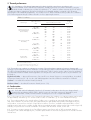
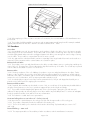
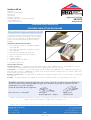
Xtratherm UK Ltd APPROVAL INSPECTION TESTING CERTIFICATION Park Road Holmewood Industrial Park Holmewood Chesterfield Derbyshire S42 5UY Tel: 0371 222 1033 Fax: 0371 222 1044 TECHNICAL APPROVALS FOR CONSTRUCTION Agrément Certificate 08/4613 e-mail: [email protected] website: www.xtratherm.com Product Sheet 4 XTRATHERM THIN-R INSULATION XTRATHERM THIN-R PITCHED ROOF BOARD PRODUCT SCOPE AND SUMMARY OF CERTIFICATE This Certificate relates to Xtratherm Thin-R Pitched Roof Board, a rigid polyisocyanurate modified polyurethane foam board with a composite foil facing on both sides, for use in timber pitched roofs, horizontal ceilings, dwarf walls and dormer cheeks of new and existing domestic and non-domestic buildings. AGRÉMENT CERTIFICATION INCLUDES: • factors relating to compliance with Building Regulations where applicable • factors relating to additional non-regulatory information where applicable • independently verified technical specification • assessment criteria and technical investigations • design considerations • installation guidance • regular surveillance of production • formal three-yearly review. KEY FACTORS ASSESSED Thermal performance — the product has a thermal conductivity (90/90 value) of 0.022 W·m–1·K–1, and calculations for ‘typical’ roof constructions indicate U values between 0.13 W·m–2·K–1 and 0.28 W·m–2·K–1 (see section 5). Condensation — the insulation core has a water vapour resistivity of approximately 300 MN·s·g–1·m–1 and each foil facing has a high water vapour resistance of 1000 MN·s·g–1, but the risk of interstitial condensation will depend on the construction and should be assessed for each project (see section 6). Behaviour in relation to fire — the product will not contribute to the development stages of a fire or present a smoke or toxic hazard (see section 7). Durability — the product will have a life equivalent to that of the roof structure in which it is incorporated (see section 12). The BBA has awarded this Agrément Certificate to the company named above for the product described herein. This product has been assessed by the BBA as being fit for its intended use provided it is installed, used and maintained as set out in this Certificate. On behalf of the British Board of Agrément Date of First issue: 3 May 2011 Simon Wroe Greg Cooper Head of Approvals — Physics Chief Executive The BBA is a UKAS accredited certification body — Number 113. The schedule of the current scope of accreditation for product certification is available in pdf format via the UKAS link on the BBA website at www.bbacerts.co.uk Readers are advised to check the validity and latest issue number of this Agrément Certificate by either referring to the BBA website or contacting the BBA direct. British Board of Agrément Bucknalls Lane Garston, Watford Herts WD25 9BA ©2011 Page 1 of 8 tel: 01923 665300 fax: 01923 665301 e-mail: [email protected] website: www.bbacerts.co.uk Regulations In the opinion of the BBA, Xtratherm Thin-R Pitched Roof Board, if used in accordance with the provisions of this Certificate, will meet or contribute to meeting the relevant requirements of the following Building Regulations: The Building Regulations 2010 (England and Wales) Requirement: C2(c) Resistance to moisture Comment: The risk of interstitial condensation must be assessed for each construction. The product can adequately limit the risk of surface condensation. See sections 6.1 and 6.5 of this Certificate. Requirement: L1(a)(i) Conservation of fuel and power Comment: Requirement: Regulation 7 Materials and workmanship Comment: The product is acceptable. See section 12 and the Installation part of this Certificate. The product can contribute to meeting this Requirement. See sections 5.1 and 5.2 of this Certificate. The Building (Scotland) Regulations 2004 (as amended) Regulation: 8(1) Regulation: Standard: 9 3.15 6.1(b) 6.2 Carbon dioxide emissions Building insulation envelope The product can contribute to satisfying clauses, or parts of clauses, 6.1.2(2), 6.1.6(1), 6.2.1(1)(2), 6.2.3(1), 6.2.4(2), 6.2.5(2), 6.2.6(1), 6.2.7(1), 6.2.8(2), 6.2.9(1)(2), 6.2.10(1), 6.2.11(1)(2), 6.2.12(2) and 6.2.13(1)(2) of these Standards. See sections 5.1 and 5.2 of this Certificate. Comment: Regulation: Building standards — construction Condensation The risk of interstitial condensation must be assessed for each construction. The product can adequately limit the risk of surface condensation, with reference to clauses 3.15.1(1)(2), 3.15.3(1)(2), 3.15.4(1)(2) and 3.15.5(1)(2). See sections 6.1 and 6.6 of this Certificate. Comment: Standard: Standard: Fitness and durability of materials and workmanship The product can contribute to a construction meeting this Regulation. See section 12 and the Installation part of this Certificate. Comment: 12 Building standards — conversions All comments given for this product under Regulation 9, also apply to this Regulation, with reference to clause 0.12.1(1) and Schedule 6(1). Comment: (1) Technical Handbook (Domestic). (2) Technical Handbook (Non-Domestic). The Building Regulations (Northern Ireland) 2000 (as amended) Regulation: B2 Fitness of materials and workmanship Comment: Regulation: C5 Condensation The product is acceptable. See section 12 and the Installation part of this Certificate. The risk of interstitial condensation must be assessed for each construction. See section 6.1 of this Certificate. Comment: Regulation: Regulation: F2(a)(i) F3(2) Comment: Conservation measures Target carbon dioxide Emissions Rate The product can contribute to satisfying these Regulations. See sections 5.1 and 5.2 of this Certificate. Construction (Design and Management) Regulations 2007 Construction (Design and Management) Regulations (Northern Ireland) 2007 Information in this Certificate may assist the client, CDM co-ordinator, designer and contractors to address their obligations under these Regulations. See sections: 2 Delivery and site handling (2.4) and 13 General (13.2) of this Certificate. Non-regulatory Information NHBC Standards 2011 NHBC accepts the use of Xtratherm Thin-R Pitched Roof Board, when installed and used in accordance with this Certificate, in relation to NHBC Standards, Chapter 7.2 Pitched roofs. Technical Specification 1 Description 1.1 Xtratherm Thin-R Pitched Roof Board, comprises of rigid polyisocyanurate modified polyurethane foam, faced with a composite foil facing on both sides. Page 2 of 8 1.2 The board has the nominal characteristics as shown in Table 1. Table 1 Nominal characteristic 2400 Length (mm) 1200 Width (mm) Thickness (mm) 25 to 165 (in 5 mm increments) Minimum compressive strength at 10% compression (kPa) Edge profile 150 square, tongue-and-groove, rebated 1.3 Ancillary items for use with this product, but outside the scope of this Certificate are: • roof tile underlay • Helifix InSkew 600 or similar spiral fixings • galvanized slab nails, ring-shank nails and nails • pre-treated counter battens and tiling laths • roofing slates or tiles • vapour control layer and plasterboard. 2 Delivery and site handling 2.1 The product is delivered to site in polyethylene shrink-wrapped packs containing a label bearing the manufacturer’s trade name, product description, and the BBA identification mark incorporating the number of this Certificate. 2.2 Care must be taken to avoid damaging corners and edges. 2.3 The product must be protected from prolonged exposure to sunlight and should be stored either under cover or protected with opaque polythene sheeting. Where possible, packs should be stored inside. If stored outside, the product should be stacked flat and raised above ground level, and not in contact with ground moisture. 2.4 The product must not be exposed to open flame or to other ignition sources. Assessment and Technical Investigations The following is a summary of the assessment and technical investigations carried out on Xtratherm Thin-R Pitched Roof Board. Design Considerations 3 General 3.1 Xtratherm Thin-R Pitched Roof Board is suitable for use as thermal insulation in new and existing pitched roofs of dwellings or other buildings with similar temperature and humidity conditions: • above and between sloping rafters • between and below sloping rafters • below horizontal ceiling joists • between and/or to the inner face of studs in dwarf walls and dormer cheeks. 3.2 Roofs should be designed and constructed in accordance with the relevant clauses of BS 5250 : 2002, BS 5268-2 : 2002, BS 5534 : 2003 and BS 8212 : 1995. 3.3 Although the product will contribute to the buckling and racking strength of the roof, normal cross-bracing must be incorporated. 3.4 During installation, care should be exercised to ensure that the product is not subjected to any construction, or foot traffic loads. Roof timbers of adequate strength should be used to support such loads. 3.5 It is essential that detailing and jointing of the product achieves a convection-free envelope (see also section 6.3). Any gaps should be filled, and/or taped. Ridges, abutments and penetrations should also be sealed. Flue pipes passing through the insulation should be suitably sleeved. 3.6 Proper care and attention must be given to maintaining the integrity/continuity of vapour control layers. 3.7 The requirements/provisions of fire stops should be considered with regard to national Building Regulations. 4 Practicability of installation The product is designed to be installed by a competent general builder, or a contractor, experienced with this type of product. Page 3 of 8 5 Thermal performance 5.1 Calculations of the thermal transmittance (U value) should be carried out in accordance with BS EN ISO 6946 : 2007 and BRE Report (BR 443 : 2006) Conventions for U-value calculations, using the declared thermal conductivity (90/90) value of 0.022 W·m–1·K–1 and a foil surface emissivity (ε) of 0.2. When considering insulation requirements, designers should refer to the detailed guidance contained in the documents supporting the national Building Regulations. The U value shown in Table 2 indicate that the product can contribute to a roof achieving typical design U values referred to in those supporting documents. Table 2 U values(1) Element type Existing sloping roof with ventilated space below underlay New sloping roof with LR underlay Horizontal ceiling Dwarf wall or dormer cheek (1) (2) (3) (4) Thin-R thickness(2) (mm) and location with respect to rafter/joist or stud Timber dimensions (mm) inside between outside U value (W·m–2·K–1) 50 x 100 at 400 centres 70 80 100 50 50 50 — — — 0.20 0.18 0.15 50 x 150 at 400 centres 60 60 65 60 75 100 — — — 0.20 0.18 0.15 47 x 100 at 600 centres 50 — — 50 80 75 100 100 — 50 50 — 0.18 0.18 0.16 0.16 47 x 150 at 600 centres — — — 135(4) 75 130 — 50 50 0.20 0.18 0.13 47 x 100 at 400 centres 85 115 (3) — — 0.16 0.13 35 x 100 at 600 centres 80 110 (3) — — 0.16 0.13 38 x 89 at 600 centres 75 55 — 80 — — 0.28 0.19 38 x 140 at 600 centres — 55 120(4) 80 — — 0.28 0.19 (3) (3) Plasterboard taken as 12.5 mm at 0.25 W·m–1·k–1 and all timber % taken from BR 443. Nearest available thickness. 100 mm mineral wool at 0.040 W·m–1·k–1. Includes a 0.01 W·m–2·k–1 gap correction. 5.2 The product can contribute to maintaining continuity of thermal insulation at junctions between elements and openings. For Accredited Construction Details the corresponding psi values in BRE Information Paper IP1/06 Assessing the effects of thermal bridging at junctions and around openings, Table 3 may be used in carbon emission calculations in Scotland and Northern Ireland. Detailed guidance for other junctions and on limiting heat loss by air infiltration can be found in: England and Wales — Approved Documents to Part L and for new thermal elements to existing buildings, Accredited Construction Details (version 1.0). See also SAP 2009 Appendix K and the iSBEM User Manual for new-build Scotland — Accredited Construction Details (Scotland) Northern Ireland — Accredited Construction Details (version 1.0). 6 Condensation Interstitial condensation 6.1 Roofs and walls will adequately limit the risk of interstitial condensation when they are designed and constructed in accordance with BS 5250 : 2002, Sections 8.3 and 8.4 respectively, Appendix D, and BRE Report (BR 262 : 2002) Thermal insulation: avoiding risks for roofs in England and Wales. 6.2 For the purposes of assessing the risk of interstitial condensation, the insulation core vapour resistivity may be taken as approximately 300 MN·s·g–1·m–1 and a resistance value of 1000 MN·s·g–1 for each individual foil facing. 6.3 The product installed on the internal surface of rafters, joists or studs has an intrinsically high vapour resistance and, when installed in a continuous layer with tightly butted joints and durably taped, filled/sealed gaps and joints, will provide a convection-free envelope of high vapour resistance. Therefore, a suitable vapour-permeable, roof tile underlay may be laid over the insulation boards without a ventilated air space. When using a high resistance (type HR) underlay, the space below it must be ventilated in accordance with BS 5250 : 2002, section 8.4. 6.4 To minimise moisture entering the roof an effective vapour control layer such as 125 µm minimum thickness polyethylene with sealed and lapped joints, should be placed under the inclined ceiling between the insulation and the internal finish. Page 4 of 8 Surface condensation 6.5 Roofs and walls will adequately limit the risk of surface condensation when the thermal transmittance (U value) does not exceed 0.35 W·m–2·K–1 and 0.7 W·m–2·K–1 respectively at any point and the junctions are designed in accordance with Limiting thermal bridging and air leakage : Robust construction details for dwellings and similar buildings TSO 2002, BRE Information Paper IP1/06 or section 5.2 of this certificate. 6.6 Roofs and walls will adequately limit the risk of surface condensation when the thermal transmittance (U value) does not exceed 1.2 W·m–2·K–1 at any point. Guidance may by obtained from BS 5250 : 2002, section 8, or section 5.2 of this Certificate. Additional information can be found in BRE Report (BR 262 : 2002) Thermal insulation: avoiding risks. 7 Behaviour in relation to fire 7.1 When installed with an internal lining board securely fixed to timber, eg 12.5 mm thick plasterboard, the product will be contained between the element and internal lining board until one is destroyed. Therefore, the product will not contribute to the development stages of a fire until the lining is compromised. 7.2 The use of the product will not affect the fire rating obtained by tiled or slated roofs when evaluated by assessment or test to BS 476-3 : 2004. 7.3 Elements must incorporate cavity barriers at edges, around openings, at junctions with fire resisting elements and in cavities in accordance with the relevant provisions of the national Building Regulations and relevant purpose group. The design and installation of cavity barriers must take into account any anticipated differential movement. 8 Strength The product, when installed in accordance with the manufacturer’s instructions and this Certificate, will resist the loads likely to be met during installation and in service. 9 Structural stability (over rafter application only) 9.1 Resistance to wind uplift will depend largely on the building geometry and its geographical location and should be calculated in accordance with BS EN 1991-1-4 : 2005 or BS 6399-2 : 1997. Snow loadings should be calculated in accordance with BS EN 1991-1-3 : 2003 or BS 6399-3 : 1988. 9.2 When calculating the fixing spacing required to resist the calculated loadings, the requirements of BS 5268-2 : 2002 or BS EN 1995-1-1 : 2004 should be followed where possible. Further guidance can be obtained from the Certificate holder. The Certificate holder must advise on the use of the correct proprietary fixings and approved nails and fixing capacity in accordance with BS 5268-2 : 2002 or BS EN 1995-1-1 : 2004. 10 Resistance to moisture An effective roof tile underlay will protect the product from wind-driven snow or rain penetrating the tiles/slates in service. 11 Maintenance As the product is placed within the roof and has suitable durability (see section 12), maintenance is not required. 12 Durability The product will have a life equivalent to that of the roof structure in which it is incorporated. Installation 13 General 13.1 Installation of Xtratherm Thin-R Pitched Roof Board as shown in Figure 1 must be in accordance with the relevant clauses of BS 5534 : 2003, the manufacturer’s instructions and can be carried out in all conditions normal to roofing work. 13.2 The product is light to handle but some handling difficulties may be experienced in windy conditions. Since the product will not support the weight of operatives, appropriate care must be taken during installation and tiling. 13.3 The product can be cut easily using a sharp knife or fine tooth saw but care must be taken to prevent damage, particularly to edges. Damaged boards should not be used. 13.4 A tight fit must be ensured between the product and rafters, the product at the ridge and at roof/wall junctions. 13.5 It is important to fill/seal gaps and joints in the insulation envelope (see section 3.5). 13.6 Where the product is installed in traditional and timber-frame construction, cavity barriers at the junction of the external wall and roof space should be provided. 13.7 Roof tiles or slates are installed in accordance with the relevant clauses of BS 5534 : 2003. Page 5 of 8 Figure 4 Use of cavity board Xtratherm 13.8 When applying roof tiles or slates to a warm roof construction, the recommendations of the manufacturer must be followed. 13.9 The product should be installed in conjunction with an appropriate internal lining board for example standard gypsum plasterboard to BS EN 520 : 2004 in accordance with BS 8212 : 1995. 14 Procedure Over rafters 14.1 A treated-timber stop rail, the same thickness as the product, is fixed to the rafters close to the eaves to provide a firm fixing point for the counter battens. The product is laid over the rafters commencing at the stop rail. The product should be tightly butted and positioned in a staggered pattern with all the joints running from eaves to ridge occurring over the rafters. The procedure is continued until the whole area is covered. 14.2 Any gaps must be sealed with flexible sealant or expanding foam. Large-headed clout nails can be used as a temporary securing measure until the counter battens are secured into place. Between and over rafters 14.3 The product is cut to size and placed between the rafters on timber batten carriers or sarking clips nailed up the slope of the roof. The upper face of the product must be kept flush with the top of the rafter. The second layer is placed over the rafters as described in sections 14.1 and 14.2. Between rafters 14.4 Following completion of the roof cladding, the product is cut to size and placed between the rafters. Timber battens or clips are fixed to the inner face of the rafters allowing sufficient depth for the insulation to sit flush with the underside of the rafters. A ventilation gap of 50 mm must be maintained between the product and roof tile underlay to minimise the risk of condensation, unless a vapour permeable underlay is used. 14.5 A sealed polythene vapour control layer with a minimum thickness 125 µm with lapped and sealed joints is placed over the rafter face before applying the internal finish. Between and below rafters 14.6 If required, after installation as described in section 14.4, a second layer of the product may be added below the rafters running transverse to the first, to provide a staggered layer, and secured accordingly. 14.7 The product should be butted tightly against each other to prevent gaps. Taping the joints with a acrylic adhesive foil tape provides an effective vapour control layer and an air permeability barrier. To achieve an adequate bond, the product should be clean and free from any contamination. 14.8 The insulation is sealed at all service penetrations. Horizontal ceiling above a room in the roof — below joists only 14.9 Mineral wool is packed between the ceiling joists; flush with the upper surface of the ceiling joist. 14.10 The product is temporarily fixed to the underside of the timber joists. 14.11 The line of the timber joists is marked on the boards to allow fixing of plasterboard (see sections 14.7 and 14.8). External finishing — warm roofs 14.12 The vapour-permeable roof tile underlay is laid in accordance with the manufacturer’s instructions. Page 6 of 8 14.13 Treated counter battens (minimum 38 mm deep) are fixed at each rafter run from eaves to ridge using the proprietary fixings at the required centres in accordance with the fixing manufacturer’s instructions. The counter batten is also fixed to the anchor batten, with short lengths being tightly butted together. 14.14 Tiling laths are fixed horizontally at spacings to suit the specified tiles or slates with the nails penetrating the full depth of the laths and counter batten. Finishing 14.15 The plasterboard is fixed over the product and secured with conventional nails or screws to the appropriate length, and finished as normal. Dwarf walls and dormer cheeks — between studs 14.16 Timber stop battens or clips are fixed to the inner face of the studs allowing sufficient depth for the insulation to sit flush with the inside of the studs. The product is cut to size and placed between the studs and held in place with clout nails. The procedure continues in the same manner as shown in section 14.5. Dwarf walls and dormer cheeks — between studs and lining 14.17 Timber stop battens or clips are fixed to the inner face of the studs allowing sufficient depth for the insulation to sit flush with the inside of the studs. The product is cut to size and placed between the studs and held in place with clout nails. 14.18 A second layer of the product is temporarily fixed to the inner face of the timber studding. 14.19 The line of the timber studs is marked on the boards to allow fixing of plasterboard. 14.20 The product should be butted tightly against each other to prevent gaps. Taping the joints with an acrylic adhesive foil tape provides an effective vapour control layer and an air permeability barrier. To achieve an adequate bond, the product should be clean and free from any contamination. 14.21 The insulation is sealed at all service penetrations. 14.22 The plasterboard is fixed over the product and secured with conventional nails or screws to the appropriate length, and finished as normal. Technical Investigations 15 Tests Tests were carried out by the BBA on Xtratherm Thin-R Pitched Roof Board in accordance with BS EN 13165 : 2008 to determine: • dimensional stability • compressive strength • thermal conductivity • bowing under a thermal gradient • flatness under one-sided wetting. 16 Investigations 16.1 The manufacturing process was examined, including the methods adopted for quality control, and details were obtained of the quality and composition of the materials used. 16.2 Results of test data to BS EN 13165 : 2008 were assessed in relation to: • dimensions • squareness • value. 15.3 An assessment of the risk of interstitial condensation was made. 15.4 An assessment was made of typical constructions which achieve the design U values. Bibliography BS 476-3 : 2004 Fire tests on building materials and structures — Classification and method of test for external fire exposure to roofs BS 5250 : 2002 Code of practice for control of condensation in buildings BS 5268-2 : 2002 Structural use of timber — Code of practice for permissible stress design, materials and workmanship BS 5534 : 2003 Code of practice for slating and tiling (including shingles) BS 6399-2 : 1997 Loading for buildings — Code of practice for wind loads BS 6399-3 : 1988 Loading for buildings — Code of practice for imposed roof loads BS 8212 : 1995 Code of practice for dry lining and partitioning using gypsum plasterboard Page 7 of 8 BS EN 520 : 2004 Gypsum plasterboards — Definitions, requirements and test methods BS EN 1991-1-3 : 2003 Eurocode 1 : Actions on structures — General actions — Snow loads BS EN 1991-1-4 : 2005 Eurocode 1 : Actions on structures — General actions — Wind actions BS EN 1995-1-1 : 2004 Eurocode 5 : Design of timber structures — General — Common rules and rules for buildings BS EN 13165 : 2008 Thermal insulation products for buildings — Factory made rigid polyurethane foam (PUR) products — Specification BS EN ISO 6946 : 2007 Building components and building elements — Thermal resistance and thermal transmittance — Calculation method Conditions of Certification 17 Conditions 17.1 This Certificate: • relates only to the product/system that is named and described on the front page • is granted only to the company, firm or person named on the front page — no other company, firm or person may hold or claim any entitlement to this Certificate • is valid only within the UK • has to be read, considered and used as a whole document — it may be misleading and will be incomplete to be selective • is copyright of the BBA • is subject to English law. 17.2 Publications and documents referred to in this Certificate are those that the BBA deems to be relevant at the date of issue or re-issue of this Certificate and include any: Act of Parliament; Statutory Instrument; Directive; Regulation; British, European or International Standard; Code of Practice; manufacturers’ instructions; or any other publication or document similar or related to the aforementioned. 17.3 This Certificate will remain valid for an unlimited period provided that the product/system and the manufacture and/or fabrication including all related and relevant processes thereof: • are maintained at or above the levels which have been assessed and found to be satisfactory by the BBA • continue to be checked as and when deemed appropriate by the BBA under arrangements that it will determine • are reviewed by the BBA as and when it considers appropriate. 17.4 In granting this Certificate, the BBA is not responsible for: • the presence or absence of any patent, intellectual property or similar rights subsisting in the product/system or any other product/system • the right of the Certificate holder to manufacture, supply, install, maintain or market the product/system • individual installations of the product/system, including the nature, design, methods and workmanship of or related to the installation • the actual works in which the product/system is installed, used and maintained, including the nature, design, methods and workmanship of such works. 17.5 Any information relating to the manufacture, supply, installation, use and maintenance of this product/system which is contained or referred to in this Certificate is the minimum required to be met when the product/system is manufactured, supplied, installed, used and maintained. It does not purport in any way to restate the requirements of the Health & Safety at Work etc Act 1974, or of any other statutory, common law or other duty which may exist at the date of this Certificate; nor is conformity with such information to be taken as satisfying the requirements of the 1974 Act or of any statutory, common law or other duty of care. In granting this Certificate, the BBA does not accept responsibility to any person or body for any loss or damage, including personal injury, arising as a direct or indirect result of the manufacture, supply, installation, use and maintenance of this product/system. British Board of Agrément Bucknalls Lane Garston, Watford Herts WD25 9BA ©2011 Page 8 of 8 tel: 01923 665300 fax: 01923 665301 e-mail: [email protected] website: www.bbacerts.co.uk