1
Operating instructions
Optical particle monitor
UK
706364 / 00
11 / 2013
LDP100
Contents
1 Symbols used������������������������������������������������������������������������������������������������������ 3
2 Safety instructions����������������������������������������������������������������������������������������������� 3
2.1 Basic safety instructions�������������������������������������������������������������������������������� 3
2.2 Laser-specific safety instructions������������������������������������������������������������������� 4
3 Functions and features���������������������������������������������������������������������������������������� 5
3.1 Applications��������������������������������������������������������������������������������������������������� 5
3.2 Restriction of the application area����������������������������������������������������������������� 5
4 Function��������������������������������������������������������������������������������������������������������������� 6
4.1 Measuring principle��������������������������������������������������������������������������������������� 6
4.2 Processing of the measured signals�������������������������������������������������������������� 6
4.2.1 Determination of the range number to ISO 4406:99����������������������������� 6
4.2.2 Sequential data output via the analogue output����������������������������������� 7
5 Installation ���������������������������������������������������������������������������������������������������������� 8
5.1 Assembly drawings���������������������������������������������������������������������������������������� 8
5.2 Installation����������������������������������������������������������������������������������������������������� 9
5.3 Conditions������������������������������������������������������������������������������������������������������ 9
5.3.1 Pressure stability���������������������������������������������������������������������������������� 9
5.3.2 Volume flow and viscosity������������������������������������������������������������������� 11
5.3.3 Free of bubbles and water droplets���������������������������������������������������� 12
6 Electrical connection������������������������������������������������������������������������������������������ 13
7 Controls and LED indicators������������������������������������������������������������������������������ 14
8 Menu structure��������������������������������������������������������������������������������������������������� 15
9 Parameter setting ��������������������������������������������������������������������������������������������� 16
9.1 Operating mode������������������������������������������������������������������������������������������� 16
9.2 Alarm configuration�������������������������������������������������������������������������������������� 17
9.3 Analogue output configuration��������������������������������������������������������������������� 17
9.4 Default �������������������������������������������������������������������������������������������������������� 18
9.5 Configuration flow���������������������������������������������������������������������������������������� 18
9.6 Communication�������������������������������������������������������������������������������������������� 18
9.7 Configuration display����������������������������������������������������������������������������������� 18
9.8 Sensor parameters�������������������������������������������������������������������������������������� 18
9.8.1 Flow settings��������������������������������������������������������������������������������������� 18
2
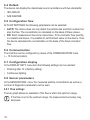
10 Communication������������������������������������������������������������������������������������������������19
10.1 CAN bus����������������������������������������������������������������������������������������������������19
10.2 CANopen Object Directory of the device���������������������������������������������������20
11 Operation���������������������������������������������������������������������������������������������������������20
11.1 Troubleshooting�����������������������������������������������������������������������������������������21
12 Technical data and scale drawing��������������������������������������������������������������������21
13 Maintenance, repair, disposal��������������������������������������������������������������������������22
14 Appendix (UK)�������������������������������������������������������������������������������������������������23
UK
14.1 Communication Profile Area����������������������������������������������������������������������23
1 Symbols used
►
→
Instructions
Cross-reference
Important note
Non-compliance can result in malfunction or interference.
Information
Supplementary note.
2 Safety instructions
2.1 Basic safety instructions
• Please read the product description prior to setup of the unit. Ensure that the
product is suitable for your application without any restrictions.
• In order to guarantee the correct condition of the device during operation it is
necessary to use the device only for media to which the wetted materials are
sufficiently resistant (→ Technical data).
• Responsibility as to whether the measurement devices are suitable for the
respective application lies with the operator. The manufacturer assumes no
liability for consequences of misuse by the operator.
• Installation, electrical connection, set-up, operation and maintenance of the
unit must only be carried out by qualified personnel authorised by the machine
operator. Improper installation and use of the device results in a loss of
warranty claims.
3
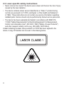
2.2 Laser-specific safety instructions
• Never remove the covers! The device uses a laser and there is the risk of injury
caused by the laser radiation.
• The device contains a laser sensor classified as a "Class 1" product during
normal use (pursuant to 21 CFR, subchapter J of the Health and Safety Act
of 1968). These instructions do not contain any service information regarding
installed parts. Service should only be performed by trained service personnel.
• The device has been evaluated and tested in accordance with EN610101:1993 ("Safety Requirements For Electrical Equipment For Measurement,
Control, and Laboratory Use"), IEC 825-1:1993 ("Safety of Laser Products")
and other relevant industry norms (e.g. ISO 4406, ISO 6149-2).
A label indicating the laser class pursuant to 21CFR has been applied to the
device. A copy of this label can be seen in the drawing below.
4
3 Functions and features
The device is a compact particle monitor for continuous monitoring of the
contamination and wear in hydraulic fluids and lubricants.
3.1 Applications
The device is designed for use in pressure lines with not more than 420
bar.
The device is equipped with two Minimess connections via which it is connected
to the pressure system. The device is usually installed in a bypass by Teeing off a
UK
pressure line. Then the system pressure provides the required flow.
The system pressure can vary but it must not have any peaks or high fluctuations during the measurement (→ 5.3.1 Pressure stability). Relatively
constant pressure conditions are to be aimed for. If pressure peaks are
present it may be necessary to throttle back the system pressure downstream of the counter.
To ensure reliable operation, the device requires a constant volume flow
between 50 and 400 ml/min. This value applies to both directions of flow;
the direction can be freely selected.
In additon to the cleanliness level the device also displays the housing
temperature.
3.2 Restriction of the application area
Correct measurement presupposes that the measured fluid is free of
bubbles and water droplets.
Pressure Equipment Directive (PED): The device complies with section
3, article (3) of the Directive 97/23/EC and is designed and manufactured
for media of fluid group 2 (stable gases and non-superheated liquids) in
accordance with the sound engineering practice.
5
4 Function
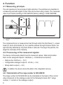
4.1 Measuring principle
The unit operates to the principle of light extinction. The particles are classified in
a measuring cell with regard to their size and number using a laser. The measured
value is provided according to ISO 4406:99 (factory setting) or SAE AS4059E.
2
1
U
3
t
U: Voltage of the photodiode
t: Time
The components are: a measurement cell through which the fluid flows (1), a laser
beam (3) and a photo diode (2). As a particle passes through the laser beam, the
light intensity detected by the photo diode is reduced. The larger the particle, the
larger the decrease of the intensity.
4.2 Processing of the measured signals
The device continuously determines the measured values / data and provides
them via the assigned outputs / interfaces (→ 6 Electrical connection):
• Data via the CAN bus (→ 10.1)
• Configurable analogue output 4...20 mA (→ 9.3)
• Binary alarm output (→ 9.2).
In addition the device stores the data in the integrated memory.
4.2.1 Determination of the range number to ISO 4406:99
The range number to ISO 4406:99 can be calculated on the basis of the current
value measured on the analogue output to the following formula (OZ = range
number, I = current on the analogue output):
6
26
26
OZ = 16 mA x I [mA] 4
The current range covers the range numbers to ISO 4406:99 from 0 to 26.
A current value of 4 mA corresponds to a range number of 0; a current value of 20
mA corresponds to a range number of 26. The values are on a linear characteristic
curve.
Range number
Iout in mA
0
4
13
12
26
20
UK
4.2.2 Sequential data output via the analogue output
If sequential data output is selected, the range numbers are output one after the
other:
1
20
1
4 µm
6 µm
14 µm
21 µm
4
2
x
1: start sequence
y: current in mA,
x: time in seconds
After the start sequence the measured values are output in 4 size channels *) as
current pulses.
*) Size channel 6 μm, for example, includes all particles ≥ 6 μm during the
measurement
7
5 Installation
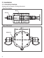
5.1 Assembly drawings
Drawing with the relevant mounting dimensions:
View from below:
M6x7
12
M16x2
View of the back:
61
M5x5,5
8
5.2 Installation
The device is equipped with two M16x2 Minimess connections via which it is
connected to the pressure system. The device is usually installed in a bypass by
Teeing off a pressure line. Then the system pressure provides the required flow.
To get meaningful measuring results, the installation must be located in
a position that is relevant for the measuring task. It is also recommended
to install the device at a location that is easily accessible to ensure good
readability of the display.
Rule for the bypass length: the shorter the better. With increasing length
there is a higher risk that larger particles settle.
UK
Make sure that the pressure is sufficiently high to guarantee the required
flow volume, in particular within Minimess lines (→ 5.3.2 Volume flow and
viscosity).
5.3 Conditions
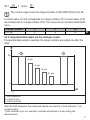
5.3.1 Pressure stability
The system pressure can vary but it must not have any peaks or high fluctuations during the measurement. Relatively constant pressure conditions
are to be aimed for. It may be necessary to decrease the system pressure
after counting.
From experience it is recommended to connect a control oil line. Usually
there are moderate pressure conditions at this point; furthermore a volume
flow of 400 ml/min is no problem for the control circuit at usual conditions.
If there is no control circuit, a possible filter/coolant circuit is a good alternative.
9
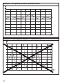
Example: acceptable pressure characteristics
x
Example: unacceptable pressure characteristics
x
10
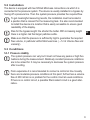
5.3.2 Volume flow and viscosity
To ensure reliable operation, the device requires a constant volume flow
between 50 and 400 ml/min. This value applies to both directions of flow;
the direction can be freely selected.
Make sure that the pressure is sufficiently high to guarantee the required
volume flow, in particular with high viscosities.
The following figure illustrates pressure difference against volume flow for various
viscosities:
20
410 mm²/s
18
16
14
12
10
197 mm²/s
8
6
55 mm²/s
4
2
0
0
0,1
0,2
0,3
0,4
0,5
0,6
0,7
0,8
x
y: Δp in bar, x: volume flow in l/min
You can estimate the required pressure difference (Δp) for a flow volume using the
figure above.
11
UK
5.3.3 Free of bubbles and water droplets
There must be no bubbles or water droplets in the fluid to be measured.
Otherwise the result of the measurement may be falsified.
High range numbers are usually an indicator for bubble and water droplet
formation in the measured fluid. It may also be possible to recognise this
state by the same range numbers in the size channels. Evaluation with the
naked eye is very unreliable.
The following can help reduce the formation of bubbles or water droplets:
►► Introduce flow or pressure regulation downstream of the measuring point.
►► If the volume flow is generated by a pump: Aim for low-pulsation. Install the
pump upstream of the measuring point since installation on the suction side
may lead to bubbles forming which might result in an incorrect particle count.
12
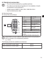
6 Electrical connection
• The unit must be connected by a qualified electrician.
• The national and international regulations for the installation of electrical equipment must be adhered to.
• Voltage supply to EN50178, SELV, PELV, VDE0100-410/A1.
• Use a screened sensor cable.
►► Disconnect power.
►► Connect the unit as follows:
1
2
3
2
3
4
5
1 8
7
6
4
5
6
7
8
L+
L
CANL
CANH
In
Out 1
Out 2
GND 1
screen
1:
2:
3:
4:
5:
6:
7:
L+
LCANL
CANH
In
Out 1
Out 2
UK
9...33 V DC
0 V DC ¹)
CAN communication
CAN communication
Switching input ²)
4...20 mA
Alarm; open collector output.
Signal ground Out 1
8: GND 1
screen ¹)
¹) L- and screen are connected to the
housing.
²) Low level activates measuring cycle
Output Out2 is an open collector output without short-circuit protection; it
has no overload or over temperature protection!
Imax = 0.5 A
The following sockets are available as accessories:
8-pole, screened M12 socket; straight
8-pole, screened M12 socket; angled
E80021
E80022
13
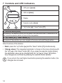
7 Controls and LED indicators
1
2
1: LED green [power]
2: LED red [alarm]
3: Display
4: Selection button [Enter]
3
4
5
5: "Up" button [▲] / "down" button [▼]
4: Selection button [Enter]
By means of the selection button you can jump to the next menu level; if values are to be
set, press the selection button to jump to the next position.
5: "Up" button [ ▲ ] / "down" button [▼]
By means of these buttons you can navigate in the menu and scroll through entries.
Other functions of the buttons:
• Back: press the "up" button [▲] and the "down" button [▼] simultaneously.
• Change values: The requested parameter is chosen in the menu structure with
the "up" [▲] or the "down" button [▼]. If you press the selection button [Enter],
the parameter value can be changed with the "up" [▲] or "down" [▼] button.
Any changes are confirmed by pressing the selection button [Enter].
If you jump to the next higher level before pressing the selection button, the
changes are not saved.
14
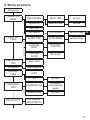
8 Menu structure
Start screen
OPERATION
MODE
TIME CONTROL
DELAY TIME
set time
DIGITAL I/O
SAMPLE TIME
set time
AUTOMATIC
STD. ALARM
set limit values
ALARM TYPE
FILTER MODE
set limit values
BUTTON
ALARM SETTINGS
ALARM MEMORY
LOWPASS
FILTER
ANALOG SETTING
select output
STANDARD
select standard
FLOW SETTINGS
AUTO
COMMUNICATION
DISPLAY SETT.
UK
AUTO OFF /
CONFIRM
filter length
FIX
set value
BAUDRATE CAN
CAN speed
and terminating
resistor
NODE-ID CAN
set value
CONTINUOUS /
DIM AFTER 10s
15
MEASUREMENT
HARDWARE
SENSOR PARAM.
LANGUAGE
OPER. HOURS
ERROR INFOS
select language
FLOW ADJUST
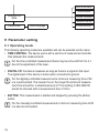
9 Parameter setting
9.1 Operating mode
The following operating modes are available and can be selected via the menu:
• TIME CONTROL: The device works with a set time of measurement and idle
time between the measurements.
For the time-controlled measurement there may be a time shift of 2 to 3 s
due to the adjustment of the laser.
• DIGITAL I/O: the device measures as long as there is a signal on the input.
The digital input of the device is active when connected to ground.
For the digitally-controlled measurement a minimum measuring time of 60
s is recommended. The cleaner the oil, the longer the minimum measurement time should be. A cleanliness level of 15 according to ISO 4406:99
should be checked with a measurement time of 120 s.
• BUTTON: This measurement is started and stopped by pressing the (Enter)
button.
For the manually-controlled measurement a minimum measuring time of 60
s is also recommended.
16
• AUTOMATIC: Here the measuring time is dynamically controlled and depends
on the flow and the particle concentration.
This mode is recommended for changing operating conditions since it automatically defines the measurement time and therefore achieves optimum
results of measurement.
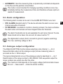
9.2 Alarm configuration
The following alarm modes can be set in the ALARM SETTINGS menu item:
• STD. ALARM (standard alarm): The device activates the alarm as soon as a UK
channel exceeds a threshold.
• FILTER MODE: Is suitable to monitor a cleaning process; the device activates
the alarm when all channels set have dropped below the threshold.
The alarm thresholds can be set separately for each size channel: If a size
class should not be taken into account, its value must be "0".
The digital alarm output (Out2) connects to ground (negative switching).
The max. switching voltage is 36 V.
9.3 Analogue output configuration
The ANALOG SETTING function allows selecting a size channel (→ 4.2.2
Sequential data output via the analogue output) whose measuring value is
provided via the 4...20mA output.
The typical characteristic curve of the analogue output is described in → 4.2.1
Determination of the range number to ISO 4406:99. With sequential output the
range numbers are output one after the other.
The maximum load depends on the supply voltage (technical data at www.
ifm.com → New search → Enter the article number).
17
9.4 Default
The device can display the cleanliness level in accordance with two standards:
• ISO 4406-99
• SAE AS4059E
9.5 Configuration flow
At FLOW SETTINGS the following parameters can be selected:
• AUTO: The device does not only detect the particle size and their number but
also the flow. The concentration is calculated on the basis of these values.
• FIX: Each measurement has some imprecision. If the volumetric flow quantity
is constant and known, it is possible to set this fixed value on the device. Then
the device calculates the concentration on the basis of the fixed volumetric
flow.
9.6 Communication
The CAN bus can be configured by means of the COMMUNICATION menu
(→ 10 Communication).
9.7 Configuration display
In the DISPLAY SETT. menu item the following settings can be selected:
• Dimming after 10 s (factory setting).
• Continuous lighting.
9.8 Sensor parameters
In the SENSOR PARA. menu the measured particle concentration as well as a
number of diagnostic parameters can be seen.
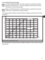
9.8.1 Flow settings
The bar graph allows an evaluation if the flow is within the optimum range.
If the flow is not in the optimum range, the measurement accuracy may
decrease.
18
10 Communication
10.1 CAN bus
The CAN bus is a serial bus system in which all connected stations are equal.
That means that each control device (CAN node) can transmit and receive. Due
to the linear structure of the network the bus system is completely available for all
stations if one station fails.
The CAN interface of the present device conforms to the CAN 2.0B Active
Specification. The data packages correspond to the format shown in the
following figure (the figure is for illustration purposes, the implementation UK
conforms to the CAN 2.0B specification).
Start CAN-ID DLC Data CRC ACK END Space
1
2
3
4
5
6
7
1: Start of message
2: Address, service type (e.g. PDO, SDO)
3: Data Length Code
4: User data (up to 8 bytes)
5: CyclicRedundancyChecksum
6: Receiver sets bit to "Low"
7: End of message
The factory setting of the Node ID of the device is: 32
On delivery the device is set to a baud rate of 125 Kbits/s.
19
10.2 CANopen Object Directory of the device
The device is based on a CANopen profile. Basically the CANopen profiles
are organised in a table ("object directory"). All device profiles share the
"communication profile" by means of which the basic device data is enquired or
set. Examples of this device data are:
• Device designation
• Hardware and software version
• Error status
• Used CAN identifier
The device profiles describe the special capabilities and parameters of a
"class" of devices.
The table in chapter 14 Appendix (UK) contains communication-relevant elements
to be found in the object directory of the device. Apart from a few exceptions the
possible settings conform to the CANopen standard as described in "DS-301".
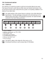
11 Operation
When the supply voltage has been applied, the unit is in the operating mode.
It carries out the measurement and evaluation functions and generates output
signals according to the set parameters.
LED operation indicators:
Operating status
LED green
(power)
LED red
(alarm)
Device ready for opeON
OFF
ration, no alarm ¹)
Device ready for opeON
ON
ration, alarm ¹).
¹) observe parameter setting (parameter: ALARM SETTINGS)
Out 2
(Alarm)
OFF
ON
The device is factory-set to a time-controlled measurement with a measuring period of one minute and an idle time of 10 seconds. After power-on
the device starts automatically with the measuring cycles and displays the
results.
20
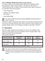
11.1 Troubleshooting
Error
•No communication
via the CAN bus
possible.
•Current outputs
< 4 mA
All size channels display identical values.
•Laser current high
•Photo voltage low
(Feedback via CAN
bus)
Possible cause
Cable not correctly
connected.
The operating voltage
is outside the specified
range.
Air in the oil
Air in the oil
Contaminated cell
Recommended measures
►► Check the correct electrical connection of the sensor, the data cable
and the power cable.
►► Observe the specified wiring.
►► Always operate the device between
9 and 33 V DC.
►► Connect the device on the pressurised side.
►► Increase the distance to the pump.
►► Connect the device on the pressurised side.
►► Increase the distance to the pump.
►► Clean the device using clean oil or
solvent (e.g. Isopropanol).
UK
12 Technical data and scale drawing
Technical data and scale drawing at www.ifm.com → New search → Enter the
article number.
21
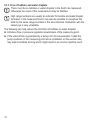
13 Maintenance, repair, disposal
•
•
•
•
Clean the unit if badly soiled.
In case of damage replace the unit.
It is not possible to repair the unit.
After use dispose of the unit in an environmentally friendly way in accordance
with the applicable national regulations.
• In case of returns ensure that the unit is free from soiling, especially of
dangerous and toxic substances. For transport only use appropriate packaging
to avoid damage of the unit.
More information at www.ifm.com
22
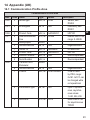
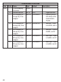
14 Appendix (UK)
14.1 Communication Profile Area
Indx
1000
Communication Profile Area
S-idx Name
Type
Default
0
device type
u32, ro 0x194
1001
0
Errorregister
u8, ro
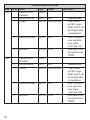
1008
1017
0
0
u32, ro 0x4C445031
u16, rw 0x1388
0
1
Product Code
producerheartbeat
time
identityobject
Numberofentries
Vendor ID
Product Code
Revision Number
Serial Number
Transmit PDO1
Parameter
Numberofentries
COB-ID
2
transmission type
u8, rw
5
eventtimer
u16, rw 0x1F4
1018
0
1
2
3
4
1800
record
u8, ro
u32, ro
u32, ro
u32, ro
u32, ro
record
0x00
0x04
0x0069666
0x4C445031
0x64
u8, ro 0x05
u32, rw 0x180+NodeID
0xFF
Description
Sensor, see
DS404
mandatory, see
DS301
UK
LDP100
heartbit time in ms,
range: 0..65535
largestsubindex
ifm electronic
LDP100
Device dependant
Device dependant
largestsubindex
COB-ID used
by PDO, range:
0x181..0x1FF, can
be changed while
not operational
cyclic + synchronous, asynchronous values:
1-240, 254, 255
event timer in ms
for asynchronous
TPDO1
23
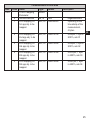
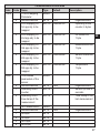
Indx
1801
1802
24
Communication Profile Area
S-idx Name
Type
Default
Description
Transmit PDO2
record
Parameter
0
Numberofentries
u8, ro 0x05
largestsubindex
1
COB-ID
u32, rw 0x280+NodeID
COB-ID used
by PDO, range:
0x281..0x2FF, can
be changed while
not operational
2
transmission type
u8, rw 0xFF
cyclic + synchronous, asynchronous values:
1-240, 254, 255
5
eventtimer
u16, rw 0x1F4
event timer in ms
for asynchronous
TPDO2
Transmit PDO3
record
Parameter
0
Numberofentries
u8, ro 0x05
largestsubindex
1
COB-ID
u32, rw 0x380+NodeID
COB-ID used
by PDO, range:
0x381..0x3FF, can
be changed while
not operational
2
transmission type
u8, rw 0xFF
cyclic + synchronous, asynchronous values:
1-240, 254, 255
5
eventtimer
u16, rw 0x1F4
event timer in ms
for asynchronous
TPDO3
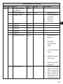
Communication Profile Area
Indx S-idx Name
Type
Default
1A00
TPDO1 Mapping
record
Parameter
0
Numberofentries
u8, ro 0x05
u32, co 0x20000220
1
PDO Mapping for
1st app obj. to be
mapped
2
3
4
5
PDO Mapping for
2nd app obj. to be
mapped
PDO Mapping for
3rd app obj. to be
mapped
PDO Mapping for
4th app obj. to be
mapped
PDO Mapping for
5th app obj. to be
mapped
u32, co 0x20010108
Description
largestsubindex
Operating hours
time stamp of the
measurement,
4 bytes
UK
ISO4µm, 1 byte in
2001h, sub 01
u32, co 0x20010208
ISO6µm, 1 byte in
2001h, sub 02
u32, co 0x20010308
ISO14µm, 1 byte
in 2001h, sub 03
u32, co 0x20010408
ISO21µm, 1 byte
in 2001h, sub 04
25
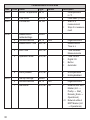
Communication Profile Area
Indx S-idx Name
Type
Default
1A01
TPDO2 Mapping
record
Parameter
0
Numberofentries
u8, ro 0x05
u32, co 0x20000220
1
PDO Mapping for
1st app obj. to be
mapped
2
3
4
5
26
PDO Mapping for
2nd app obj. to be
mapped
PDO Mapping for
3rd app obj. to be
mapped
PDO Mapping for
4th app obj. to be
mapped
PDO Mapping for
5th app obj. to be
mapped
u32, co 0x20020108
Description
largestsubindex
Operating hours
time stamp of the
measurement,
4 bytes
SAE4µm, 1 byte
im 0x2002, sub 01
u32, co 0x20020208
SAE6µm, 1 byte in
0x2002, sub 02
u32, co 0x20020308
SAE14µm, 1 byte
in 0x2002, sub 03
u32, co 0x20020408
SAE21µm, 1 byte
in 0x2002, sub 04
Communication Profile Area
Indx S-idx Name
Type
Default
1A02
TPDO3 Mapping
record
Parameter
0
Numberofentries
u8, ro 0x05
u32, co 0x20000120
1
PDO Mapping for
1st app obj. to be
mapped
u32, co 0x20030108
2
PDO Mapping for
2nd app obj. to be
mapped
u32, co 0x20030708
3
PDO Mapping for
3rd app obj. to be
mapped
u32, co 0x20030808
4
PDO Mapping for
4th app obj. to be
mapped
u32, co 0x20040008
5
PDO Mapping for
5th app obj. to be
mapped
record
2000
Time related
parameters of the
sensor
0
Numberofentries
u8, ro 0x02
1
Operating hours
u32, ro
counter
u32, ro
2
Operating hours
time stamp of the
measurement
2001
ISO measurement record
0
Numberofentries
u8, ro 0x04
1
ISO4µm
u8, ro
2
ISO6µm
u8, ro
3
ISO14µm
u8, ro
4
ISO21µm
u8, ro
Description
largestsubindex
Operating hours
counter, 4 bytes
Oil status bits,
1 byte
UK
Measurement bits,
1 byte
Sensor status bits,
1 byte
Temperature
1 byte
largestsubindex
Sensor up time in
seconds
Time stamp of the
last measurement
largestsubindex
27
Indx
2002
28
Communication Profile Area
S-idx Name
Type
Default
SAE measurement record
0
Numberofentries
u8, ro 0x04
1
SAE4µm
u8, ro
2
SAE6µm
u8, ro
3
SAE14µm
u8, ro
4
SAE21µm
u8, ro
Description
largestsubindex
Indx
2003
Communication Profile Area
S-idx Name
Type
Default
Condition Monitoarray
ring Bitfield
0
Numberofentries
u8, ro 0x08
1
Oilspecificbits
u8, ro
Description
0:
1:
2:
2
3
4
5
6
7
8
reserved
reserved
reserved
reserved
reserved
Measurement info
Sensor alarm
u8, ro
u8, ro
u8, ro
u8, ro
u8, ro
u8, ro
u8, ro
largestsubindex
Concentration limit
exceeded
High flow
Low flow
0:
Measurement in
process
1:
Automatic
measurement
mode
2:
I/O measurement
mode
3:
Manual measurement mode
4:
Alarm mode filter /
standard
Laser current high
Laser current low
Photo voltage high
Photo voltage low
Temperature high
Temperature low
0:
1:
2:
3:
4:
5:
29
UK
Indx
2004
Communication Profile Area
S-idx Name
Type
Default
Sensor Temperature s8, ro
Description
Oiltemperature
in °C
Flow index (0..500)
1: Start of a
measurement
2: Stop of a measurement
2005
2020
Flow index
Commando
u16, ro
u8, wo
2030
record
0
1
Measurement
relatedsettings
Numberofentries
Measurement Time
2
Hold Time
u32, rw
3
Operation Mode
u16, rw
0:
1:
2:
3:
largestsubindex
Measurement
Time in s
Time betweenMeasurements
Time Control
Digital I/O
Button
Automatic
4
Historydisable
u16, rw 0
0:
1:
Historyenabled
Historydisabled
0
1
Startup Settings
Numberofentries
Startmode
record
u8, ro 0x01
u16, rw 0x0
2031
u8, ro 0x08
u32, rw
0:
largestsubindex
Network with NMT
Master (Init →
PreOp → Start_
Remote_Node →
Operational)
> 0: Network without
NMT Master (Init
→ Operational)
30
Indx
2100
2101
Communication Profile Area
S-idx Name
Type
Default
Readmem control
record
functions
0
Numberofentries
u8, ro 0x04
1
Size ofhistorymeu32, ro devicedepenmory
dand
2
Usedhistorymem
u32, ro
3
Reading pointer,
dataset
u32, ro
4
Clear historymemory
Readmem Initiate
segmented SDO
data Upload
u16,
wo
u16, ro
0
Description
1:
largestsubindex
size of memory in
datasets
used datasets
within memory
UK
(corresponds
internaly to write
pointer)
autoincrementing
read pointer to a
dataset for history
memory reading;
can be between 0
and current write
pointer
clearmemory
Appropriate Pointer has to be set
(with 2100sub3)
before start
reading.
Size of the record
will be sent back
on reading
31