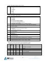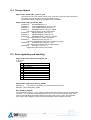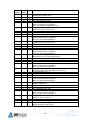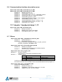
1
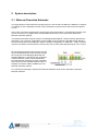
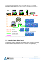
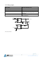
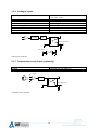
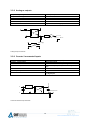
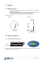
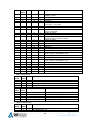
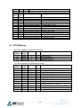
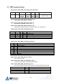
®
User Manual
EtherControl Controlled Node – Mix Module EM1 / EM2
SHF Communication Technologies AG
Division Automation
September 2006, Preliminary
1
SHFA-H-ETC-06CNM21-005-EN --all rights reserved
Content:
1
2
3
4
5
6
7
8
General information.......................................................................................................................... 4
1.1
Copyright................................................................................................................................... 4
1.2
Intended use ............................................................................................................................. 4
1.3
Symbols / Abbreviations ........................................................................................................... 4
System description ........................................................................................................................... 5
2.1
Ethernet Powerlink Networks.................................................................................................... 5
2.2
Controlled Node – EtherControl................................................................................................ 6
2.3
Construction .............................................................................................................................. 7
2.4
Processor unit ........................................................................................................................... 7
2.5
Periphery unit ............................................................................................................................ 7
Technical data .................................................................................................................................. 8
3.1
Mechanical parameters............................................................................................................. 8
3.1.1
General information ........................................................................................................... 8
3.1.2
Distance to the casing wall ................................................................................................ 8
3.1.3
Environmental Specification .............................................................................................. 8
3.1.4
Storage and transportation conditions ............................................................................... 9
3.1.5
Connectors......................................................................................................................... 9
3.2
Electrical parameters ................................................................................................................ 9
3.2.1
Supply of the module ......................................................................................................... 9
3.2.2
Protection........................................................................................................................... 9
3.2.3
Ethernet connection ......................................................................................................... 10
3.2.4
Binary inputs .................................................................................................................... 10
3.2.5
Binary outputs .................................................................................................................. 11
3.2.6
Analogue inputs ............................................................................................................... 12
3.2.7
Temperature sensor inputs (optionally) ........................................................................... 12
3.2.8
Analogue outputs ............................................................................................................. 13
3.2.9
Counter / Incremental inputs............................................................................................ 13
Installation ...................................................................................................................................... 14
4.1
Mechanical setup .................................................................................................................... 14
4.2
Electrical installation................................................................................................................ 14
4.2.1
Connection of terminals A – D ......................................................................................... 14
4.2.2
Connection of power supply ............................................................................................ 15
4.2.3
Ethernet connectors......................................................................................................... 15
Controls .......................................................................................................................................... 15
5.1
Indicators................................................................................................................................. 15
5.1.1
Display ............................................................................................................................. 15
5.1.2
Status indicators .............................................................................................................. 15
5.1.2.1
Error LED.................................................................................................................. 15
5.1.2.2
STATUS LED ........................................................................................................... 16
5.2
User elements ......................................................................................................................... 16
5.2.1
Address switches ............................................................................................................. 16
5.2.2
Control keys ..................................................................................................................... 16
5.2.3
Contrast level ................................................................................................................... 16
Technical description...................................................................................................................... 17
6.1
Module EM1 ............................................................................................................................ 17
6.2
Modul EM2 .............................................................................................................................. 18
Menu selection ............................................................................................................................... 18
7.1
Main menu .............................................................................................................................. 19
7.2
Display Inputs and Outputs ..................................................................................................... 20
7.3
Binary Input/Output simulation................................................................................................ 21
7.4
Changing of the CN IP address .............................................................................................. 22
7.5
Changing of the Gateway IP address ..................................................................................... 23
7.6
Specification of module and Powerlink data ........................................................................... 24
7.7
Show log data ......................................................................................................................... 24
7.8
Simulation enable.................................................................................................................... 24
Object dictionary............................................................................................................................. 25
8.1
Process data objects (PDO), Service data objects (SDO) and module parameters .............. 25
8.2
PDO Mapping.......................................................................................................................... 29
2
SHFA-H-ETC-06CNM21-005-EN --all rights reserved
8.3
NMT general objects ............................................................................................................... 30
8.4
Timing objects ......................................................................................................................... 31
8.5
Error signalling and handling .................................................................................................. 31
8.6
Communication interface description error ............................................................................. 33
8.7
Others ..................................................................................................................................... 33
9 Accessories .................................................................................................................................... 34
9.1
2-pin plug for the connection of voltage supply ...................................................................... 34
9.2
9-pin plug for the connection of the periphery (I/O connection).............................................. 34
9.3
Ethernet cable CAT 5 STP...................................................................................................... 34
3
SHFA-H-ETC-06CNM21-005-EN --all rights reserved
1 General information
1.1 Copyright
This manual and the illustrations contained herein are provided by SHF AG and are copyright
protected. Any reproduction, modification or translation into other languages without permission is an
offence against copyrights and is forbidden. Violations will lead to compensation claims by SHF AG.
(copyright according to DIN 34)
1.2 Intended use
The devices are to be mounted and used only for the intended application. No express warranties and
no implied warranties whether of merchantability or fitness for any particular use, or otherwise, other
then those expressly set forth herein which are made expressly in lieu of all other warranties.
Any usage or connection not described in this manual has to be coordinated with SHF AG and
requires a written confirmation.
Deviations between the product and the manual are possible. Make sure the version of the device is
corresponding to the manual. Modifications without essential technical changes do not require any
change in the manual.
1.3 Symbols / Abbreviations
EPL
BI
BO
AI
AO
A,B,Z
–
–
–
–
–
–
MN
CN
HxWxD
SpV
GND
STP
Hex
–
–
–
–
–
–
–
Ethernet Powerlink
Binary input
Binary output
Analogue input
Analogue output
Counter inputs (channels for incremental position transducers or
separate counters
Managing Node
Controlled Node
Height x Width x Depth
Power supply input
Ground
Shielded twisted pair
Hexadecimal
4
SHFA-H-ETC-06CNM21-005-EN --all rights reserved
2 System description
2.1 Ethernet Powerlink Networks
The physical base of the Ethernet Powerlink protocol is the normal Fast Ethernet 100Base-TX network.
The difference of the Powerlink protocol is the combination of asynchronous and isochronous parts in
a cycle.
In the case of real time requirements in this real time part of the network, only Ethernet Powerlink units
can be connected. To integrate other standard Ethernet devices it has to be used an Ethernet to
Ethernet Powerlink gateway.
The Ethernet Powerlink network requires one Managing Node (MN) to control the strictly deterministic
data traffic. The cycle time is dependent on the number of the connected Controlled Nodes (CN) and
the size of the asynchronous data part. With the smallest configuration (1 x MN and 1 x CN), a minimal
cycle time of 200 µs can be achieved. The accuracy of the cycles (Jitter) will generally be 1 µs or lower.
By using the asynchronous protocol part, the CN
can be IP addressed from each browser through
the connection of the Managing Node with the
standard Ethernet. In that way by the continuous
network structure remote control independent
from the Ethernet Powerlink Protocol is possible.
Direct access to the individual network units, for
example via internet, will be available up to the
Ethernet Powerlink network.
If no real time functionality is required, the Ethernet Powerlink units can be used also in standard
Ethernet networks.
5
SHFA-H-ETC-06CNM21-005-EN --all rights reserved
The topology of the Ethernet Powerlink network is very flexible. Depending on the technical
specification of the CN, standard Ethernet Hubs or Switches, a star or daisy-chain topology or a
mixture of both will be possible.
Office
Network
Internet
MN
Hub
CN
CN
Extension Module
CN
Extension Modules
CN
Internet
Office Network
CN
Extension Module
Powerlink Network
Extension Network
Example of an Ethernet Powerlink Network in connection to a super ordinate Ethernet Network.
2.2 Controlled Node – EtherControl
The EtherControl module is a compact input and output device with own controller and storage area,
as well as an Ethernet network connection. It consists of a processor and a peripheral unit.
The module contains an integrated Hub. So it will be possible to create a daisy-chain topology without
additional devices.
6
SHFA-H-ETC-06CNM21-005-EN --all rights reserved
Display
2.3 Construction
Peripheral connectors
A - B for screw or cage
clamp plug-in
Ethernet
Connectors
Address switches
Serial interface
Control Keys
Peripheral connectors
C - D for screw or cage
clamp plug-in
Power supply
Construction of the EtherControl Module
2.4 Processor unit
The processor unit of the EtherControl modules realises the I/O control, network connections, control
of the display and the keys and running customised applications like compact PLC and data storage
functions.
On delivery the module is loaded with a basic program, running standard functions.
The display shows basic information of the module as well as information about the inputs and outputs.
The keys are used for navigation through the menu. Keys and display can be used also by customised
software.
On the module sockets for the network connection are present. Other hardware connections can be
used with adapters connected to the RJ45 sockets.
2.5 Periphery unit
The peripheral unit realises the connection to the process periphery. The module has 8 connectors
with 9 pins. As standard applications are offered defined combinations of different binary and
analogue inputs and outputs and in addition customized combinations are possible.
7
SHFA-H-ETC-06CNM21-005-EN --all rights reserved
3 Technical data
3.1 Mechanical parameters
3.1.1 General information
Dimensions H x W x D
Housing material
Mounting
Installation orientation
Weight
131 x 151 x 58 mm
ABS
Clip mounting on DIN Rail
Vertically or horizontally
approx. 465 g without extension options
3.1.2 Distance to the casing wall
Right / Left
Top / Bottom
Front panel
0 mm
20 mm
40 mm
Attention:
The distance between the I/O modules and the casing walls must be kept to ensure sufficient ventilation.
3.1.3 Environmental Specification
Ambient operating temperature
Relative humidity
Operating atmospheric pressure
Pollution resistance
0 °C ... 50 °C (optio nally -20 °C ... +70 °C)
5 ... 95 %, non condensing
86 ... 108 hPa
Test according IEC 60068-2-42 und
IEC 60068-2-43
according IEC 60068-2-6
according IEC 60068-2-27
Additional measures have to be taken in the
following environments:
– dust, corrosive steams or gas
– ionising radiation
The product must not be used:
– in medical applications
– in life-supporting systems
Vibrations
Shocks
Special conditions
8
SHFA-H-ETC-06CNM21-005-EN --all rights reserved
3.1.4 Storage and transportation conditions
Temperature
Relative humidity
Atmospheric pressure
-20 °C ... +70 °C (optional -30 °C ... +80 °C)
5 ... 95 %, non condensing
66 ... 108 hPa
3.1.5 Connectors
Power supply
2-pin plug – Screw- or cage clamp plug-in
pluggable for wires up to 2,5 mm²
9-pin plug – Screw- or cage clamp plug-in
pluggable for wires up to 2,5 mm²
RJ45 plug
RJ45 plug
I/O plugs
Ethernet connections
Extension connections
3.2 Electrical parameters
3.2.1 Supply of the module
Power supply
Supply current (standard system)
Power consumption
nominal 24V ( range 9-60V DC )
< 200 mA at 24 V DC (Modul without load)
Max. 12 W
3.2.2 Protection
Protection class according EN 60 529
Conformation
Reverse voltage protection
Air/surface leakage distance
IP 20
CE
Yes
According EN 61131-2 and EN 50178 between
circuits and parts and isolated circuits, according
overvoltage category II, degree of pollution 2
Yes, between digital part and inputs and outputs
Test voltage DC 500 V
Radiated and conducted according EN 55011
Isolation
Electromagnetic emission
9
SHFA-H-ETC-06CNM21-005-EN --all rights reserved
3.2.3 Ethernet connection
Transmission hardware
Transmission rate
Interface connection
CAT5 STP or better
10/100 Base-TX, 10/100 MBit
RJ45 plug
The three Ethernet connections are standard 10/100Base-TX interfaces for CAT5 or better twisted pair
cables. Shielded twisted pair (STP) cabling is highly recommended.
The Ethernet Powerlink specification requires use of cross-over cables but in addition standard patch
cables can be used with the MN because of the build-in auto-detection of cable type.
RJ45 jack
RJ45 jack
1
2
3
4
5
6
7
8
1
2
3
4
5
6
7
8
Recommended Pin Assignment according Ethernet Powerlink specification
3.2.4 Binary inputs
Input voltage
Input current
Input frequency
Input delay
Connection
Number of inputs
Isolation
typical 24 V ( range 12-60 V DC )
approx. 2,5 mA
≤ 5 kHz
50 µs – 4 ms (adjustable)
2-wire connection
16
All inputs separated from each other and from
the digital part
Current sink
Internal electronics
Binary Input schematic
10
SHFA-H-ETC-06CNM21-005-EN --all rights reserved
3.2.5 Binary outputs
Output voltage
Output current
Output frequency
Output delay
Feedback
Connection
typical 24V (optionally 12-42V)
≤ 500 mA short-circuit proof
≤ 2 kHz
100 µs ± 50 %
Short circuit and external power detection
2-wire connection with separate ground clip
- separate output power supply together for each
output group
16 ( 2 groups ever 8 outputs )
Outputs groups separated from each other and
from the digital part
Number of outputs
Isolation
Internal electronics
12 … 40 V
5 … 60 V on request
Output
Ground
Output status
Binary output schematic
11
SHFA-H-ETC-06CNM21-005-EN --all rights reserved
3.2.6 Analogue inputs
Input voltage ranges
0 – 1 V, 0 – 5 V, 0 – 10 V
± 1 V, ± 5 V, ± 10 V
0 – 20 mA, 4 – 20 mA
12 bit (optionally 16 bit)
≤ ± 270 V: typically 80 dB
≤ ± 500 V
2-wire connection
16
separated from the digital part
Input current ranges
resolution
Common-mode rejection
Dielectric strength
Connection
Number of inputs
Isolation
Range
switching
ADC
Internal electronics
ADC supply
DC
DC
Analogue input schematic
3.2.7 Temperature sensor inputs (optionally)
Standard connection
Isolation
Pt 100 2-wire connection
separated from the digital part
Current
ADC
Internal electronics
Temperature sensor schematic
12
SHFA-H-ETC-06CNM21-005-EN --all rights reserved
3.2.8 Analogue outputs
Output voltage ranges
Output current ranges
resolution
Connection
Number of outputs
Isolation
± 10 V (5 mA)
0 – 20 mA, 4 – 20 mA
12 bit (optionally 14 bit)
2-wire connection
16
separated from the digital part
DAC
± 10 V, 0 … 20 mA
DAC supply
DC
DC
Analogue output schematic
3.2.9 Counter / Incremental inputs
Input voltage ranges
Counter- / pulse inputs
Connection
Incremental inputs
Connection
Input frequency
Isolation
typical 24 V (optionally 5 V)
Differential inputs
2-wire connection with separate ground
Differential inputs (A/B/Z) connected by internal
logic
3 x 2-wire connection
≤ 2 MHz
All inputs separated from each other and from
the digital part
Current sink
Internal electronics
Counter/Incremental input schematic
13
SHFA-H-ETC-06CNM21-005-EN --all rights reserved
4 Installation
4.1 Mechanical setup
–
–
–
The modules can be snapped directly onto a carrier rail in accordance with the European
standard EN 50022 (DIN 35).
The spacing between adjacent components, cable conduits, casing and frame sides must
be maintained for the complete field bus node according paragraph 3.1.3.
For disassembly use a screw driver for pulling down the mounting part.
Assembly instructions:
Assembly
Disassembly
1. Slip over
2. Click in
2. Turn out
1. Disengage
4.2 Electrical installation
4.2.1 Connection of terminals A – D
Top (a)
Bottom (b)
1
1
9
9
Connectors with nine contacts are used either with screw or cage clamp wire connection. Normally the
modules are delivered with screw plug-in.
14
SHFA-H-ETC-06CNM21-005-EN --all rights reserved
4.2.2 Connection of power supply
+ -
Power supply will be connected with a bipolar plug with either screw or
cage clamp wire connection. The connector can be locked with two
screws.
4.2.3 Ethernet connectors
In the modules there are two Ethernet sockets belonging to one
Ethernet port. They are internally connected via a hub. The connection
with the network is done with a RJ45 twisted pair connector.
The network connection has to be done on port Eth 0.
The indicator “Link” lights on network link, the indicator “Data” flashes on
data packets.
5 Controls
5.1 Indicators
5.1.1 Display
The modules have an alpha numerical display with two rows /
sixteen columns. The display shows the actual process data
as well as information’s about the module itself and the
communication status, e.g. errors.
The interaction with the module is done by menus shown on
the display.
It is possible to write to the display within customer specific software.
5.1.2 Status indicators
5.1.2.1 Error LED
ERROR LED function is controlled by NMT State Machine transitions.
LED OFF
LED ON
Power On, EPL cycles without errors (NMT_CT11)
EPL cycles disturbed/aborted due to communication errors (NMT_CT3,_CT6)
15
SHFA-H-ETC-06CNM21-005-EN --all rights reserved
5.1.2.2 STATUS LED
STATUS LED (Ready) function is controlled by NMT State Machine states.
LED off
LED flickering
LED single flash
LED double flash
LED triple flash
LED on
LED blinking
NMT_GS_OFF
NMT_GS_INITIALISING,
NMT_CS_NOT_ACTIVE
NMT_CS_BASIC_ETHERNET
NMT_CS_PRE_OPERATIONAL_1
NMT_CS_PRE_OPERATIONAL_2
NMT_CS_READY_TO_OPERATE
NMT_CS_OPERATIONAL
NMT_CS_STOPPED
5.2 User elements
5.2.1 Address switches
The both Hex-switches control the last byte of the IP address.
If the module communicates via the Powerlink protocol, this hex switch
also determines the module address in the real time network.
5.2.2 Control keys
The keys are used to navigate through the build in
menus. For the detailed explanation of the menus see
module menu description.
5.2.3 Contrast level
The contrast of the display can be adjusted with a little screw driver.
16
SHFA-H-ETC-06CNM21-005-EN --all rights reserved
6 Technical description
There are two kinds of modules:
1. EM1 – Multifunctional Ethernet module with binary inputs, binary outputs analogue inputs and
counter / Incremental inputs.
2. EM2 – Multifunctional Ethernet module with binary inputs, binary outputs analogue inputs,
analogue outputs and counter / Incremental inputs.
Pt100 input will be realised as analogue input by special request.
6.1 Module EM1
The Mix-Modul EM1 has the following inputs and outputs – 16 binary inputs, 7 binary outputs, 4
analogue inputs, 6 counter inputs or 2 incremental position transducer inputs A/B/Z.
Binary inputs:
The maximum input voltage is defined in production.
Input voltage
5V
10 V
12 V
Switching threshold
2,5 V
5V
6V
24 V
Standard
12 V
30 V
15 V
Binary outputs:
The supply voltage for the outputs is provided separately for the output block C via the clamp SpV.
Analogue inputs:
The type of input (voltage / current / Pt100) and the input range are defined in production.
Input range voltage:
0 – 1 V / 0 – 5 V / 0 – 10 V / ± 1 V / ± 5 V / ± 10 V
Input range current:
0 – 20 mA / 4 – 20 mA
Input for Pt100 two wire connection
Maximum input voltage and the selection of counter or incremental inputs are defined in production.
Input voltage
5V
10 V
12 V
Switching threshold
Switching hysteresis
2,5 V
± 0,2 V
5V
± 0,5 V
6V
± 0,5 V
24 V
Standard
12 V
±1V
30 V
15 V
±1V
Port configuration:
Aa
(top)
1
2
3
4
5
6
7
8
9
BI1
BI2
BI3
BI4
BI5
BI6
BI7
BI8
BI9
Ab
(bottom)
GND1
GND2
GND3
GND4
GND5
GND6
GND7
GND8
GND9
Ba
(top)
BI10
BI11
BI12
BI13
BI14
BI15
BI16
–
–
Bb
(bottom)
GND10
GND11
GND12
GND13
GND14
GND15
GND16
–
–
Ca
(top)
SpV. C+
BO1
BO2
BO3
BO4
BO5
BO6
BO7
A1+
Cb
(bottom)
GND C
GND1
GND2
GND3
GND4
GND5
GND6
GND7
A1–
Da
(top)
B1+
Z1+
A2+
B2+
Z2+
AI1+
AI2+
AI3+
AI4+
Db
(bottom)
B1–
Z1–
A2–
B2–
Z2–
AI1–
AI2–
AI3–
AI4–
17
SHFA-H-ETC-06CNM21-005-EN --all rights reserved
6.2 Modul EM2
The Mix-Modul EM2 has additionally 2 analogue outputs
Analogue outputs:
The analogue output voltage or current are defined in production.
Output range voltage:
± 10 V
Output range current:
0 – 20 mA / 4 – 20 mA
Port configuration:
Aa
(top)
1
2
3
4
5
6
7
8
9
BI1
BI2
BI3
BI4
BI5
BI6
BI7
BI8
BI9
Ab
(bottom)
GND1
GND2
GND3
GND4
GND5
GND6
GND7
GND8
GND9
Ba
(top)
BI10
BI11
BI12
BI13
BI14
BI15
BI16
AO1+
AO2+
Bb
(bottom)
GND10
GND11
GND12
GND13
GND14
GND15
GND16
GND1
GND2
Ca
(top)
Cb
(bottom)
SpV. C+
BO1
BO2
BO3
BO4
BO5
BO6
BO7
A1+
GND C
GND1
GND2
GND3
GND4
GND5
GND6
GND7
A1–
Da
(top)
B1+
Z1+
A2+
B2+
Z2+
AI1+
AI2+
AI3+
AI4+
Db
(bottom)
B1–
Z1–
A2–
B2–
Z2–
AI1–
AI2–
AI3–
AI4–
7 Menu selection
After power on the display will show the actual status of the
inputs (top row) and outputs (bottom row) as standard
display for instance
The selection can be made by the keys
ESC
▲
,
,
0010000100000000
0100000000000000
▼
and
ENTER .
18
SHFA-H-ETC-06CNM21-005-EN --all rights reserved
7.1 Main menu
With the arrow keys can be scrolled trough the menu and with the "ENTER"
key the appropriate submenu can be selected.
A return to the standard display is made by the "ESC" key.
ESC
The following menu options can be selected from the main menu:
Standard display
▲
▼
0000000000000000
0000000000000000
▲
7.4. Changing of the CN IP address
ENTER
7.5. Changing of the Gateway IP
address
ENTER
7.6. Specification of module and
Powerlink data
ENTER
7.7. Show log data
ENTER
7.8. Simulation enable
▼
General–Simulat.
Disable
▲
ENTER
▼
Show Log Asc.
▲
7.3. Binary Input / Output simulation
▼
Status Powerlink
▲
ENTER
▼
Chg. Def. Gateway
192.168.100.254
▲
7.2. Display Inputs and Outputs
▼
Change IP. Curr:
192.168.100.0
▲
ENTER
▼
Simulate Inputs
Simulate Outputs
▲
Back step to
standard display
▼
19
SHFA-H-ETC-06CNM21-005-EN --all rights reserved
7.2 Display Inputs and Outputs
By using the "ENTER" key it is possible to scroll trough the menu as described to display the binary
and analogue inputs and outputs and the counter or frequency values.
ESC
ENTER
Standard display
0000000000000000
0000000000000000
Back step to
standard display
top: 16 binary inputs
bottom: 7 binary outputs
(starting from the left side)
ENTER
0: 00.00 1: 00.00
2: 00.00 3: 00.00
Analogue input value / floating
point number cannel 0 to 3
ENTER
0: FFFF
2: FFFF
1: FFFF
3: FFFF
Analogue input value
hexadecimal cannel 0 to 3
ENTER
DAO[mA] DA1[mA]
+0.0000
+0.0000
Analogue output value / floating
point number cannel 0 and 1
ENTER
DAO hex
FFFF
DA1 hex
FFFF
Analogue output value
hexadecimal cannel 0 and 1
ENTER
C.0,1,2
0.0
0.0
0.0
Counter- /Frequency inputs
st
cannel 0,1 and 2 (1 A,B,Z)
0.0
0.0
Counter- /Frequency inputs
nd
cannel 3,4 and 5 (2 A,B,Z)
ENTER
C.3,4,5
0.0
ENTER
20
SHFA-H-ETC-06CNM21-005-EN --all rights reserved
7.3 Binary Input/Output simulation
In this menu the binary inputs and outputs can be pre set for simulation. Only after release under
menu point 7.8., the simulation will be activated. It can be simulated only the 7 outputs (bottom raw –
starting from the left side).
By operation of the arrow keys selected channel flashes in each case (blue figured) and can be
changed over "ENTER". Simulated channels are inversely shown.
With the "ESC" key it is possible to return to the main menu. The simulated values are stored.
ESC
Selection of the input/output channel
▲
Back step to
the main menu
▼
Input/Output
simulated to
0 (Low)
ENTER
0000000000000000
0000000000000000
▲
0000000000000000
0000000000000000
▼
ENTER
ENTER
0000000000000000
0000000000000000
▼
▲
▼
……..
.…….
▲
0
1000000000000000
0000000000000000
ENTER
ENTER
0000000000000000
0000000000000000
▲
Input/Output
simulated to 1
(High)
▼
21
SHFA-H-ETC-06CNM21-005-EN --all rights reserved
7.4 Changing of the CN IP address
The IP address for Ethernet Powerlink networks is fixed on 192.168.100.XXX. The differentiation of
the CN is made by the lowest address byte. This address part is specified individually by the
adjustment of the Address switches ID1 and ID2 for each module.
If the modules are used in other networks the three higher bytes can be adjusted by the menu option
"Change IP...". The setting takes place byte by byte via increase or decrease of the address part value.
By operation of the "ENTER" key selected channel flashes in each case (blue figured).
It is to be noted that without key actuation after 10 seconds the choose values are rejected. Pressing
the "ESC" key within the 10 s the new address will be stored. Subsequently, a restart of the software
of the module takes place.
If the lowest address byte was changed by the address switches, the new IP address will only be
stored after the confirmation by pressing the "ESC" key and the following restart of the software.
ESC
IP ( r e j e c t : 1 0 s ) :
192. 168. 100. 000
Saving IP. . .
ENTER
ESC
New IP saved
Restart NOW
IP ( r e j e c t : 1 0 s ) :
192. 168. 100. 000
ENTER
ESC
IP ( r e j e c t : 1 0 s ) :
192. 168. 100. 000
Back step to
standard display
New IP rejected
ENTER
Back step to
the main menu
22
SHFA-H-ETC-06CNM21-005-EN --all rights reserved
7.5 Changing of the Gateway IP address
The Gateway IP address for Ethernet Powerlink networks is fixed on 192.168.100.254.
If the modules are used in other networks the three higher bytes can be adjusted by the menu option
"Chg. Def. Gateway...". The setting takes place byte by byte via increase or decrease of the address
part value. By operation of the "ENTER" key selected channel flashes in each case (blue figured).
It is to be noted that without key actuation after 10 seconds the choose values are rejected. Pressing
the "ESC" key within the 10 s the new address will be stored. Subsequently, a restart of the software
of the module takes place.
ESC
DWG (reject:10s)
192. 168. 100. 254
Saving DWG. . .
ENTER
ESC
DWG (reject:10s)
192. 168. 100. 254
New Def. Gateway
Restart NOW
ENTER
ESC
DWG (reject:10s)
192. 168. 100. 254
Back step to
the main menu
ENTER
ESC
DWG (reject:10s)
192. 168. 100. 254
New DGW rejected
ENTER
Back step to
the main menu
23
SHFA-H-ETC-06CNM21-005-EN --all rights reserved
7.6 Specification of module and Powerlink data
Depending on the selection, the type of the module with the implemented software version or cycle
and error of Ethernet Powerlink protocol will be displayed.
▲
▼
Typ: EM2
Version: V0.12
ESC
▲
▼
Cycle : 0ms
Error: 0
▲
Back step to
the main menu
▼
7.7 Show log data
This menu point will be used only for manufacturing and service for error analysing.
7.8 Simulation enable
This item in the main menu controls the simulation of all inputs. The simulation will be enabled or
disabled by the "ENTER" key.
The main menu will not be left. With the arrow keys it can be scrolled further thru the main menu.
General–Simulat.
Disable
ENTER
General–Simulat.
Enable
24
SHFA-H-ETC-06CNM21-005-EN --all rights reserved
8 Object dictionary
The object dictionary of the CN is accessible by SDO communication via the MN.
Most objects are statically pre-defined by a configuration file stored on the CN. Objects can be
changed dynamically by SDO communication from the MN or a modified file can be downloaded and
the CN be restarted.
8.1 Process data objects (PDO), Service data objects (SDO) and
module parameters
General List of PDOs and parameter objects addressable via SDO
– Manufacture specific (not all modules implement all objects):
Size Access Default Description
Index Subindex
2000h
binary Inputs
0= Off (0V), 1= On (24V)
0
1
ro
2
number of entries
1
1
ro
Input 0-7
2
1
ro
Input 8-15
2001h
binary output overload
0=ok , 1=overload
0
1
ro
1
number of entries
1
1
rw
0
Output 0-6
2002h
binary Output Polarity
0=True, 1=Inverted
0
1
ro
1
number of entries
1
1
rw
0
Output 0-6
2003h
binary Input Filter
0=500us, 1=2ms
1
1
ro
Input 0-7
2
1
ro
Input 8-15
2006h
binary Output Error Mode
(0=keep output, 1= use error value)
0
1
ro
1
number of entries
1
1
rw
7Fh
Output 0-6
2007h
binary Output Error Value
0
1
ro
1
number of entries
1
1
rw
0
Output 0-6
2200h
binary Outputs
0= Off (0V), 1= On (24V)
0
1
ro
1
number of entries
1
1
rw
0
Output 0-6
2320h
binary Outputs external Read Back
0
1
ro
1
number of entries
1
11
ro
0
Outputs 0-6 real value
0= Off (0V), 1= On (24V)
25
SHFA-H-ETC-06CNM21-005-EN --all rights reserved
Index
Subindex
Size
Access
Default Description
0
1-4
1
2
ro
ro
4
0
0
1-2
1
2
ro
rw
2
0
0
1-4
1
2
ro
rw
4
0
0
1-4
1
2
ro
rw
4
1
0
1-4
1
1
ro
rw
4
0
0
1-4
1
2
ro
rw
4
0
0
1-4
1
2
ro
rw
4
0
0
1-4
1
4
ro
rw
4
0
0
1-4
1
2
ro
rw
4
0
0
1-4
1
1
ro
rw
4
0
0
1-2
4
1
4
rw
ro
rw
2
-
0
1-2
1
4
ro
ro
2
-
0
1-2
1
2
ro
rw
2
00C6h
2401h
2411h
2431h
2432h
2433h
2461h
2462h
2463h
2464h
2465h
2800h
2802h
2803h
analog Inputs
number of entries
Input Channel 0-3 (I16)
0= 0V, 7FFFh= +10V, 8000h= -10V
analog Outputs
number of entries
Output Channel 0-3 (I16)
0= 0V, 7FFFh= +10V, 8000h= -10V
analog Input Offset
number of entries
Offset Channel 0-3 (I16)
Analog Input Scale
number of entries
Scale Channel 0-3 (I16)
HW range/mode Register
number of entries
HW range/mode Channel 0-3 (U8)
analog Input Average Enable
number of entries
Enable Input Average Channel 0-3 (U16)
0= disabled, 1= enabled
analog Input Average Depth
number of entries
Input Average Depth Channel 0-3 (U16)
analog Input Average Time
number of entries
Input Average Time (µs) Channel 0-3 (U32)
analog Input Filter Frequency
number of entries
Filter Frequency (Hz) Channel 0-3 (U16)
possible values for Butterworth:
125 Hz, 500 Hz, 1000 Hz, 2000 Hz
analog Input Filter Type
number of entries
Filter Type Channel 0-3 (U8)
0= disabled
nd
1= low pass Butterworth, 2 order
Pulse/Frequency Counter (U32)
number of entries
Pulse Counter (U32)
Time Counter (U32)
number of entries
Time x 250ns (U32)
Counter Mode (U16)
number of entries
Mode (U16)
26
SHFA-H-ETC-06CNM21-005-EN --all rights reserved
Hardware Range/Mode Register (Object 2433h) :
Bit
Description
2-0
000 : +- 10V
001 : +- 5V
010 : +- 1V
011 : reserved
100 : 0-10V
101 : 0-5V
110 : 0-1V
111 : PT100
7-3
reserved
Counter Mode Register (Object 2803h):
Bit
Description
2-0
000: count A+
001: count A010: count B+
011: count B100: count A+/A- (double evaluation)
101: count B+/B- (double evaluation)
110: count A+-/B+- (quadruple evaluation)
111: A count up, B count down
3
0: Quadrature mode according to bits 2-0 (A/B with 90° offset)
1: A is pulse input, B is direction input (0=up, 1=down) (bits 2-0 are ignored)
4
0: direction normal
1: direction inverted
6-5
00: Frequency measurement (Pulses within Periods of 100ms)
01: Period measurement (Time Counter x 250ns)
10: counting
11: counting with zero-pulse (Z)
7
0: Counter stopped
1: Counter enabled
8
0: no zero-pulse
1: zero-pulse
10-9 reserved (set to 0)
11
0: normal zero-pulse
1: inverted zero-pulse
12
0: no new value available
1: new value available (read only, internal use only – write as 0)
14-13 reserved (set to 0)
15
0: bipolar transducer (differential inputs ±)
1: unipolar transducer (A+/B+/Z+ = Input, A-/B-/Z- = GND)
General List of PDOs and parameter objects addressable via SDO
– Standard Device Profiles (not all modules implement all objects):
Index Sub- Size Access Default Description
index
6000h
binary Inputs
0= Off (0V), 1= On (24V)
0
1
ro
2
number of entries
1
1
ro
Input 0-7
2
1
ro
Input 8-15
6002h
binary Input Polarity
0=True, 1=Inverted
0
1
ro
2
number of entries
1
1
rw
0
Input 0-7
2
1
rw
0
Input 8-15
27
SHFA-H-ETC-06CNM21-005-EN --all rights reserved
Index
Subindex
Size
Access Default Description
6003h
0
1
2
1
1
1
ro
rw
rw
4
0
0
0
1
1
1
ro
rw
1
0
0
1
1
1
ro
rw
1
0
0
1
1
1
ro
rw
1
7Fh
0
1
1
1
ro
rw
1
0
0
1-4
1
2
ro
ro
4
0
0
1-2
1
2
ro
rw
2
0
0
1-4
1
2
ro
rw
4
0
0
1-4
1
2
ro
rw
4
1
6200h
6202h
6206h
6207h
6401h
6411h
6431h
RPDO (Poll-Request):
Object Sub- Value
Index
index
1400h
0
2
1
0
2
0
Object SubIndex index
1600h
0
1
2
3
binary Input Filter
0=500us, 1=2ms
number of entries
Input 0-7
Input 8-15
binary Outputs
0= Off (0V), 1= On (24V)
number of entries
Output 0-6
binary Output Polarity
0=True, 1=Inverted
number of entries
Output 0-6
binary Output Error Mode
(0=keep output, 1= use error value)
number of entries
Output 0-6
binary Output Error Value
number of entries
Output 0-6
analog Inputs
number of entries
Input Channel 0-3 (I16)
0= 0V, 7FFFh= +10V, 8000h= -10V
analog Outputs
number of entries
Output Channel 0-3 (I16)
0= 0V, 7FFFh= +10V, 8000h= -10V
analog Input Offset
number of entries
Offset Channel 0-3 (I16)
analogue Input Scale
number of entries
Scale Channel 0-3 (I16)
Description
PDO_RxCommParam_00h_REC
NumberOfEntries_U8
NodeID_U8
MappingVersion_U8
Value
Description
PDO_RxMappParam_00h_AU64
3
NumberOfEntries_U8
0008_0000_00_01_6200h binary Output 0..6 (U8)
0010_0010_00_01_6411h analogue Output 0 (I16)
0010_0020_00_02_6411h analogue Output 1 (I16)
TPDO (Poll-Response):
Object Sub- Value Description
Index
index
1800h
PDO_TxCommParam_00h_REC
0
2
NumberOfEntries_U8
28
SHFA-H-ETC-06CNM21-005-EN --all rights reserved
1
2
Object SubIndex index
1A00h
0
1
2
3
4
5
6
7
8
9
10
11
12
0
0
NodeID_U8
MappingVersion_U8
Value
Description
12
0008_0000_00_01_6000h
0008_0008_00_02_6000h
0008_0010_00_03_6000h
0008_0018_00_04_6000h
0010_0020_00_01_6401h
0010_0030_00_02_6401h
0010_0040_00_03_6401h
0010_0050_00_04_6401h
0020_0060_00_01_2800h
0020_0080_00_01_2802h
0020_00A0_00_02_2800h
0020_00E0_00_02_2802h
PDO_TxMappParam_00h_AU64
NumberOfEntries_U8
binary Input 0..7 (U8)
binary Input 8..15 (U8)
binary Output 0..6 readback (U8)
not used (always 0) (U8)
analogue Input 0 (I16)
analogue Input 1 (I16)
analogue Input 2 (I16)
analogue Input 3 (I16)
Pulse/Frequency Counter 0 (U32)
Time Counter 0 (U32)
Pulse/Frequency Counter 1 (U32)
Time Counter 1 (U32)
8.2 PDO Mapping
Rx PDO mapping (Poll-Request-Frame):
Payload Object Subindex Size Description
Offset
Index
0
6200h
1
1 binary Outputs
2-3
6411h
1
2 analogue Output 0
4-5
6411h
2
2 analogue Output 1
Tx PDO mapping (Poll-Response-Frame) :
Payload Object Subindex Size Description
Offset
Index
0
6000h
1
1 binary Inputs 0..7
1
6000h
2
1 binary Inputs 8..15
2
6000h
3
1 binary Outputs readback
3
6000h
4
1 not used, always 0
4-5
6401h
1
2 analogue Input 0
6-7
6401h
2
2 analogue Input 1
8-9
6401h
3
2 analogue Input 2
10-11
6401h
4
2 analogue Input 3
12-15
2800h
1
4 Pulse/Frequency Counter 0
16-19
2802h
1
4 Time Counter 0
20-23
2800h
2
4 Pulse/Frequency Counter 1
24-27
2802h
2
4 Time Counter 1
29
SHFA-H-ETC-06CNM21-005-EN --all rights reserved
8.3 NMT general objects
Object Index 1000h: NMT_DeviceType_U32: 0004.0191h
D31-24
D23-20
0
0
D19
D18
D17
D16
1
0
0
0
(Analogue (Analogue (Digital (Digital
Output)
Input)
Output) Input)
D15-0
Device Profile Number
401d = 191h
Object Index 1008h: NMT_ManufactDevName_VS
Manufacturer Device Name: “SHF AG”
Object Index 1009h: NMT_ManufactHwVers_VS
Manufacturer Hardware Version: “0001”
Object Index 100Ah: NMT_ManufactSwVers_VS
Manufacturer Software Version: “ECIO V0.9 (EPL 0.94, 4NetOS 2.4)”
Object Index 1018h: NMT_IdentityObject_REC
Subindex Access Size Value Description
0
ro
1
4
Number of Entries
1
ro
4 0EACh VendorId_U32
2
ro
4
80h ProductCode_U32
3
ro
4
0001h RevisionNumber_U32
4
ro
4
0
SerialNumber_U32
Object Index 1F82h: NMT_FeatureFlags_U32 (ro)
Bit Value Description
0
1
isochronous
1
0
SDO by UDP/IP
2
1
SDO by ASnd
3
0
SDO by PDO
4
0
NMT Info Services
5
0
Extended NMT State Commands
6
1
Dynamic PDO Mapping
7
0
NMT Service by UDP/IP
8-31
0
reserved
0= not supported, 1= feature supported
Object Index 1F83h: NMT_EPLVers_U8 (ro)
EPL Version 2.0: 20h
Object Index 1F8Ch: NMT_CurrNMTState_U8 (ro)
returns the current state of the NMT state machine
Object Index 1F9Eh: NMT_ResetCmd_U8 (rw)
This may be used to initiate a reset to the CN. The following values are valid:
Name
NMTInvalidService
NMTResetNode
NMTResetConfiguration
NMTResetCommunication
Value
FFh
28h
2Ah
29h
Description
returned when read
Reset CN
Reconfigure CN
Reset Communication
30
SHFA-H-ETC-06CNM21-005-EN --all rights reserved
8.4 Timing objects
Object Index 1006h: NMT_CycleLen_U32
This value can be set to enable control of the cycle time by the CN. When the actual
cycle time exceeds this value, the CN will signal an error.
The default value is 0 meaning cycle time check is disabled.
Object 1F98h: NMT_CycleTime_REC
Subindex 0:
NumberOfEntries = 9
Subindex 1:
IsochrTxMaxPayload_U16 (ro) = 32
Subindex 2:
IsochrRxMaxPayload_U16 (ro) = 0
Subindex 3:
PResMaxLatency_U32 (ro) = 20000
max. response time in ns to a PReq frame
Subindex 4:
PReqActPayload_U16 (rw) = 0
Subindex 5:
PResActPayload_U16 (rw) = 32
Subindex 6:
ASndMaxLatency_U32 (ro) = 100000
max. response time in ns to a SoA frame
Subindex 7:
MultipleCycleCnt_U8 (rw) = 0
number of multiplexed cycles (0=no multiplexed cycles)
Subindex 8:
AsyncMTUSize_U16 (rw) = 282
max. asynchronous frame size for ASnd frames
Subindex 9:
Prescaler_U16 (rw) = 2
toggle rate of the PS bit in SoC frames
8.5 Error signalling and handling
Object Index 1001h: ERR_ErrorRegister_U8
0= No Error
1= Error
Bit Description
0 Generic Error
1 n/a, always 0
2 Supply Voltage failure
3 n/a, always 0
4 Communication Error
5 n/a, always 0
6 reserved, always 0
7 0
Object Index 1003h: ERR_History_ADOM
Subindex 0:
num_entries_U8 (writing a ‘0’ will clear the error history)
Subindex 1-254: HistoryEntry_DOM
Error Handling Objects:
The cumulative counters (...Cum_U32) are counting the total number of errors. The threshold
counters (…Thr_U32) are incremented when an error occures and decremented with each
correct cycle indicating the relation between erroneous and correct cycles. The threshold
value can be set to trigger an action when the threshold counter reaches this value.
31
SHFA-H-ETC-06CNM21-005-EN --all rights reserved
Object
Index
1C0Ah
Subindex
Size
0
1
2
3
1
4
4
4
0
1
2
3
1
4
4
4
0
1
2
3
1
4
4
4
0
1
2
3
1
4
4
4
0
1
2
3
1
4
4
4
0
1
2
3
1
4
4
4
0
1
1
4
4
1C0Bh
1C0Ch
1C0Dh
1C0Eh
1C0Fh
1C10h
1C13h
Name/Description
DLL_CNCollision_REC
Monitors the Collision errors
NumberOfEntries_U8 = 3
DLL_CNCollisionCum_U32
DLL_CNCollisionThr_U32
DLL_CNCollisionThreshold_U32
When reached state is changed to
NMT_GS_RESET_COMMUNICATION
DLL_CNLossSoC_REC
Monitors the Loss of SoC events
NumberOfEntries_U8 = 3
DLL_CNLossSoCCum_U32
DLL_CNLossSoCThr_U32
DLL_CNLossSoCThreshold_U32
When reached state is changed to
NMT_CS_PRE_OPERATIONAL_1
DLL_CNLossSoA_REC
Monitors the Loss os SoA events
NumberOfEntries_U8 = 3
DLL_CNLossSoACum_U32
DLL_CNLossSoAThr_U32
DLL_CNLossSoAThreshold_U32
When reached state is changed to
NMT_CS_PRE_OPERATIONAL_1
DLL_CNLossPReq_REC
Monitors the Loss of Poll-Request events
NumberOfEntries_U8 = 3
DLL_CNLossPReqCum_U32
DLL_CNLossPReqThr_U32
DLL_CNLossPReqThreshold_U32
When reached state is changed to
NMT_CS_PRE_OPERATIONAL_1
DLL_CNSoCJitter_REC
Monitors the Jitter error (see object index 1C13h)
NumberOfEntries_U8 = 3
DLL_CNSoCJitterCum_U32
DLL_CNSoCJitterThr_U32
DLL_CNSoCJitterThreshold_U32
When reached state is changed to
NMT_CS_PRE_OPERATIONAL_1
DLL_CNCRCError_REC
Monitors CRC errors
NumberOfEntries_U8 = 3
DLL_CNCRCErrorCum_U32
DLL_CNCRCErrorThr_U32
DLL_CNCRCErrorThreshold_U32
When reached state is changed to
NMT_CS_PRE_OPERATIONAL_1
DLL_CNLossOfLink_REC
Monitors Loss of Link errors
NumberOfEntries_U8 = 1
DLL_CNLossOfLink Cum_U32
DLL_CNSoCJitterRange_U32 (ns)
defines the jitter for SoC cycles
32
SHFA-H-ETC-06CNM21-005-EN --all rights reserved
8.6 Communication interface description error
Object Index 1030h: NMT_InterfaceGroup_0h_REC
Object Index 1031h: NMT_InterfaceGroup_1h_REC
Subindex 0:
Number of Entries = 9
Subindex 1:
InterfaceIndex_U16 (ro) = 1
Subindex 2:
InterfaceDescription_VS (ro) = “HyNet32XS_EthCtrl”
Subindex 3:
InterfaceType_U8 (ro) = 6 (ethernet csmacd)
Subindex 4:
InterfaceMTU_U32 (ro) = 1500
Subindex 5:
InterfacePhysAddress_OSTR (ro) = MAC Address
Subindex 6:
InterfaceName_VS (rw) = “eth0”
Subindex 7:
InterfaceOperStatus_U8 (ro) = 0: Down, 1: Up
Subindex 8:
InterfaceAdminState_U8 (rw) = 0: Down, 1: Up
Subindex 9:
Valid_BOOL (rw) = TRUE
Object Index 1032h – 1039h: NMT_InterfaceGroup_xh_REC
Subindex 9:
Valid_BOOL (rw) = FALSE
Object Index 1F93h: NMT_EPLNodeId_REC
Subindex 0:
Number of Entries = 2
Subindex 1:
NodeId_U8 (ro), set by Hex-Switch
Subindex 2:
NodeIdByHW_BOOL (ro) = TRUE
8.7 Others
Object Index 1F99h: NMT_CnStateMachineTimeouts_REC
Subindex 0:
NumberOfEntries = 1
Subindex 1:
BasicEthernetTimeout_U32
Timeout in µs before changing from NMT_CS_NOT_ACTIVE
into NMT_CS_BASIC_ETHERNET state.
Object Index 1F50h: PDL_DownloadProgData_ADOM
Subindex 0:
Number of programs
(currently only 1 is supported, the default program)
Subindex 1:
Default Program (Firmware)
Object Index 1F51h: PDL_ProgCtrl_AU8
Subindex 0:
Number of entries
(currently only 1 is supported, the default program)
Subindex 1:
Program Control:
Read Access
Value Write Access
0
Stop program (n/a)
program stopped
1
Start program
program running
2
Reset program
program stopped
Currently a read access will always return ‘1’ and a write of ‘1’ or ‘2’ will initiate a reset
and restart of the CN. This is needed to start a new downloaded firmware (Program 1).
Object Index 1F52h: PDL_LocVerApplSw_REC
Version of the Default Program.
Subindex 0:
Number of entries (=2)
Subindex 1:
ApplSwDate_U32: Number of days since 1/1/1984
Subindex 2:
ApplSwTime_U32: ms since midnight
33
SHFA-H-ETC-06CNM21-005-EN --all rights reserved
9 Accessories
As accessories the following materials will be offered:
9.1 2-pin plug for the connection of voltage supply
–
–
screw plug-in
cage clamp plug-in
9.2 9-pin plug for the connection of the periphery (I/O connection)
–
–
screw plug-in
cage clamp plug-in
9.3 Ethernet cable CAT 5 STP
(shielded twisted pair), standard length of 2m. Cable of other lengths is available on inquiry.
SHF Communication Technologies AG • Division Automation
Wilhelm-von-Siemens-Str. 23 E • D - 12277 Berlin
+49 30 772 051 19 • +49 30 7702 9848 • [email protected] • www.shf.de
34
SHFA-H-ETC-06CNM21-005-EN --all rights reserved