1
Chapter 3
Building SubVIs
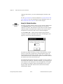
Defining Connector Terminal Patterns
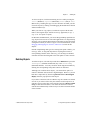
You send data to and receive data from a subVI through the terminals
in its connector pane. You define connections by choosing the number
of terminals you want for the VI and by assigning a front panel control
or indicator to each of those terminals. Only the controls and indicators
you use programmatically by wiring to the subVI require terminals on
the connector pane.
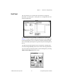
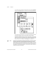
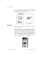
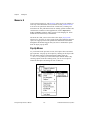
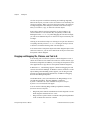
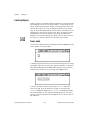
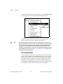
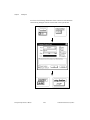
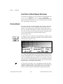
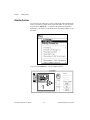
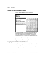
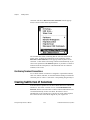
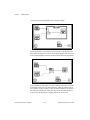
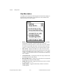
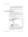
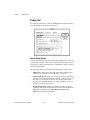
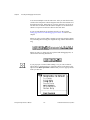
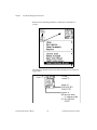
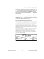
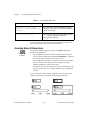
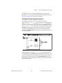
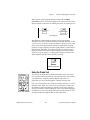
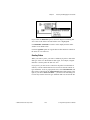
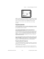
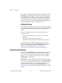
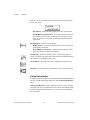
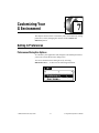
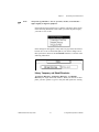
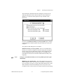
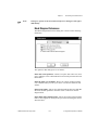
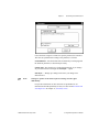
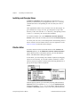
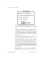
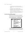
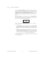
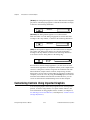
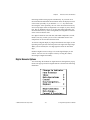
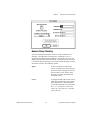
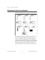
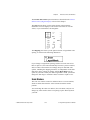
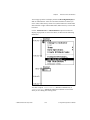
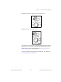
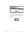
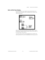
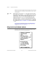
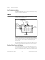
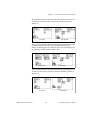
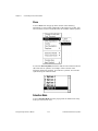
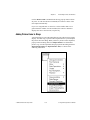
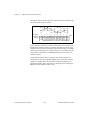
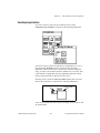
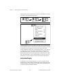
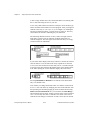
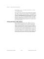
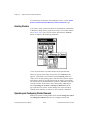
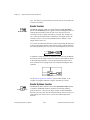
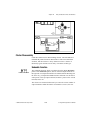
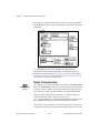
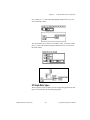
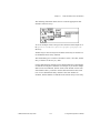
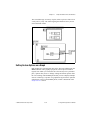
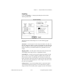
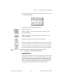
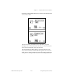
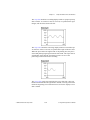
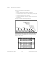
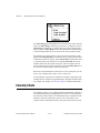
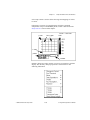
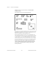
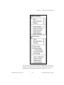
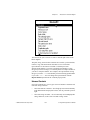
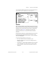
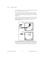
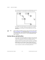
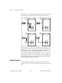
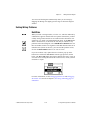
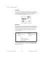
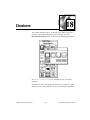
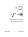
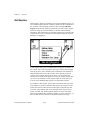
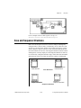
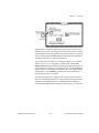
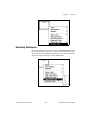
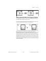
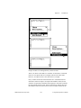
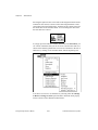
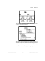
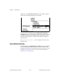
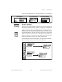
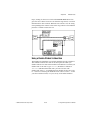
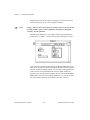
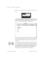
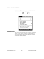
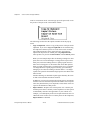
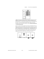
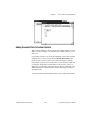
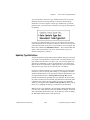
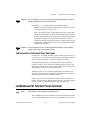
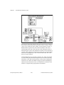
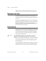
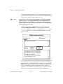
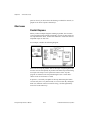
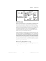
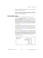
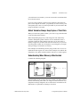
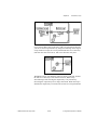
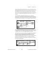
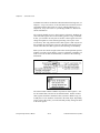
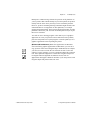
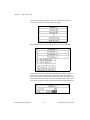
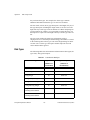
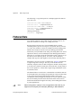
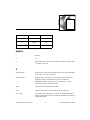
If the connector for your VI is not displayed already in the upper right
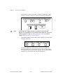
corner of the front panel, choose Show Connector from the icon pane
pop-up menu, as shown in the following illustration. The block diagram
does not have a connector pane.
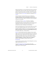
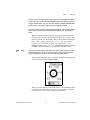
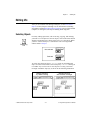
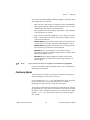
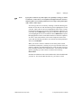
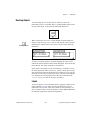
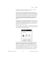
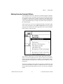
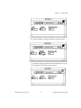
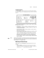
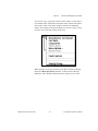
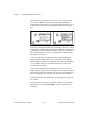
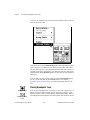
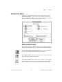
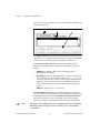
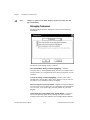
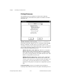
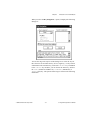
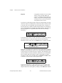
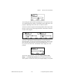
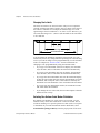
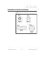
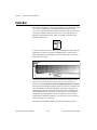
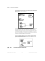
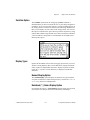
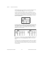
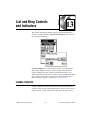
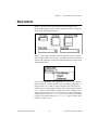
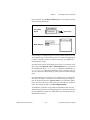
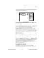
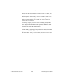
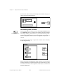
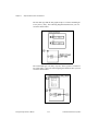
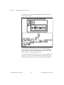
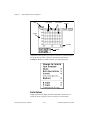
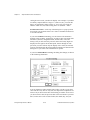
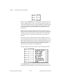
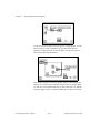
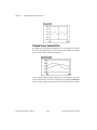
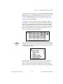
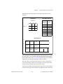
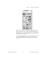
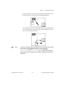
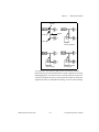
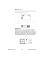
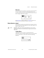
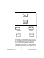
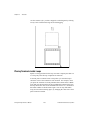
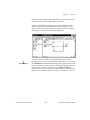
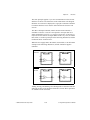
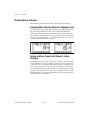
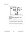
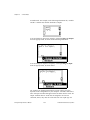
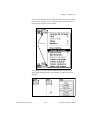
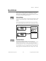
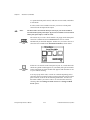
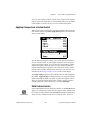
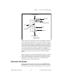
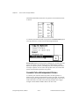
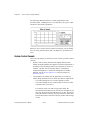
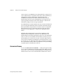
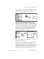
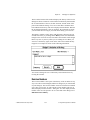
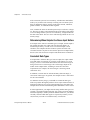
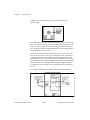
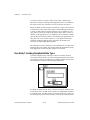
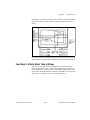
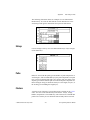
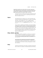
The connector replaces the icon in the upper right corner of the front
panel. G selects a terminal pattern for your VI with as many terminals
on the left of the connector pane as controls on the front panel, and as
many terminals on the right of the connector pane as indicators on the
front panel.
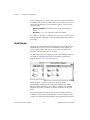
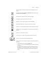
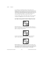
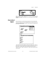
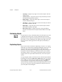
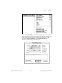
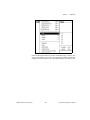
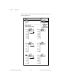
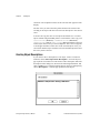
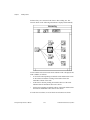
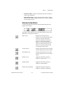
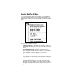
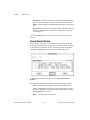
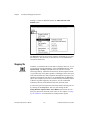
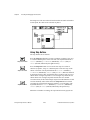
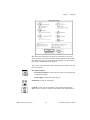
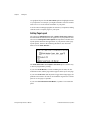
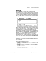
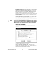
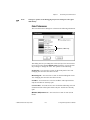
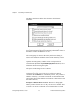
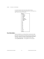
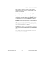
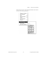
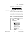
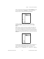
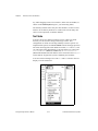
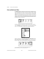
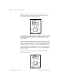
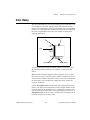
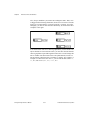
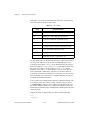
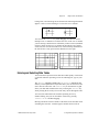
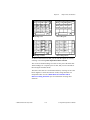
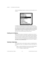
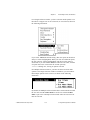
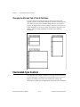
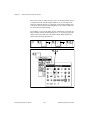
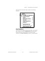
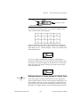
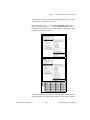
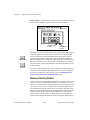
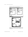
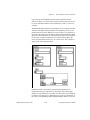
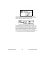
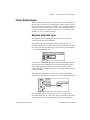
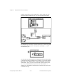
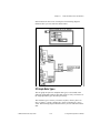
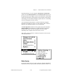
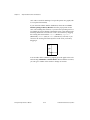
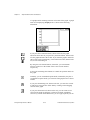
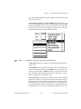
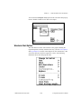
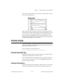
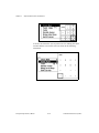
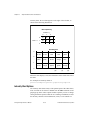
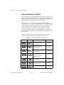
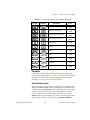
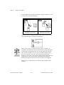
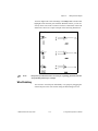
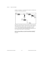
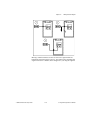
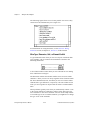
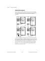
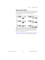
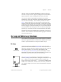
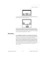
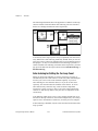
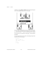
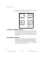
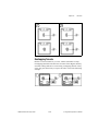
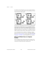
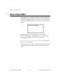
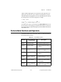
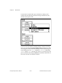
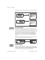
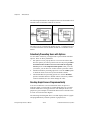
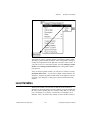
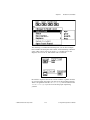
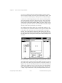
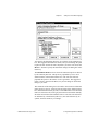
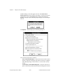
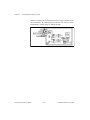
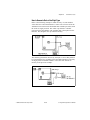
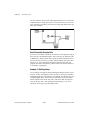
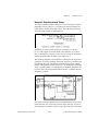
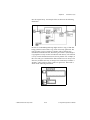
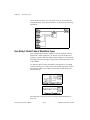
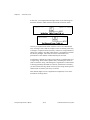
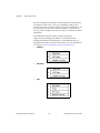
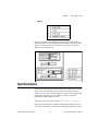
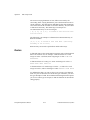
Each of the rectangles on the connector represents a terminal area, and
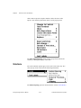
you can use them either for input to or output from the VI. If you want
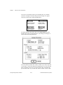
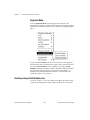
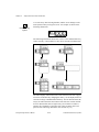
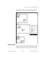
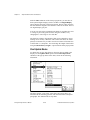
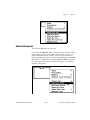
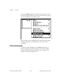
to use a different terminal pattern for your VI, you can select a different
pattern.
© National Instruments Corporation
3-5
G Programming Reference Manual