1
NavisWorks Roamer
User Manual
NavisWorks Roamer: User Manual
Table of Contents
1. Overview .................................................................................................................................
2. File Management .....................................................................................................................
2.1. File Menu .....................................................................................................................2
2.2. New Files .....................................................................................................................2
2.3. Opening Files ................................................................................................................3
2.4. Appending Files ............................................................................................................3
2.5. Saving Files ..................................................................................................................4
2.6. Saving and Renaming Files ........................................................................................... 4
2.7. Publishing Files .............................................................................................................5
2.8. Printing .........................................................................................................................5
2.8.1. Printing the Current Viewpoint ............................................................................. 5
2.8.2. Previewing Printouts ...........................................................................................5
2.8.3. Setting up printouts ............................................................................................. 6
2.9. Deleting Files ................................................................................................................6
2.10. Emailing Files .............................................................................................................6
2.11. Exporting Files ............................................................................................................7
2.11.1. Exporting to a Bitmap ........................................................................................ 7
2.11.2. Exporting to a JPEG ......................................................................................... 8
2.11.3. Exporting to a Piranesi Epix format .................................................................... 9
2.11.4. Exporting to a an .avi ........................................................................................ 9
2.11.5. Controlling the size of an image ......................................................................... 10
2.12. Quitting NavisWorks ....................................................................................................11
3. Converting Files .......................................................................................................................
3.1. File Readers .................................................................................................................12
3.1.1. NWF Files ..........................................................................................................12
3.1.2. NWD Files .........................................................................................................12
3.1.3. NWC Files .........................................................................................................13
3.1.4. DWG and DXF Files ........................................................................................... 15
3.1.5. 3DS Files ...........................................................................................................19
3.1.6. DGN and PRP Files ............................................................................................ 22
3.1.7. MAN Files ..........................................................................................................26
3.1.8. IGES Files .........................................................................................................26
3.1.9. STEP Files .........................................................................................................29
3.1.10. SolidWorks Files ...............................................................................................31
3.1.11. Inventor Files ...................................................................................................33
3.1.12. Solid Edge Files ............................................................................................... 35
3.2. File Exporters ................................................................................................................37
3.2.1. AutoCAD .nwc Exporter ...................................................................................... 37
3.2.2. MicroStation .nwc Exporter ................................................................................. 39
3.2.3. Viz .nwc Exporter ............................................................................................... 44
3.2.4. ArchiCAD .nwc Exporter ..................................................................................... 47
3.3. CAD Previewing ............................................................................................................49
3.3.1. NavisWorks Navigator for AutoCAD ..................................................................... 49
3.3.2. NavisWorks Preview for Viz and Max ................................................................... 51
4. Publishing ...............................................................................................................................
4.1. Publishing from Roamer ................................................................................................ 54
4.2. Publishing from AutoCAD .............................................................................................. 56
4.3. Publishing from MicroStation .......................................................................................... 57
4.4. NavisWorks Freedom ....................................................................................................59
5. Navigating ...............................................................................................................................
5.1. Navigation Modes .........................................................................................................63
iv
NavisWorks Roamer
5.1.1. Walking .............................................................................................................64
5.1.2. Looking Around ..................................................................................................64
5.1.3. Zooming ............................................................................................................65
5.1.4. Zooming to a Box ............................................................................................... 65
5.1.5. Panning .............................................................................................................66
5.1.6. Orbiting ..............................................................................................................66
5.1.7. Examining ..........................................................................................................66
5.1.8. Flying ................................................................................................................67
5.1.9. Spinning on a Turntable ...................................................................................... 67
5.2. Navigation Tools ...........................................................................................................68
5.3. Viewing Everything ........................................................................................................69
5.4. Viewing Selected Items ................................................................................................. 69
5.5. Focusing .......................................................................................................................69
5.6. Perspective Camera ......................................................................................................70
5.7. Orthographic Camera ....................................................................................................70
5.8. Straighten .....................................................................................................................70
5.9. Set World Up ................................................................................................................ 71
5.10. Preset Viewpoints ........................................................................................................71
5.10.1. Aligning With The X-Axis ................................................................................... 71
5.10.2. Aligning With The Y-Axis ................................................................................... 72
5.10.3. Aligning With The Z-Axis ................................................................................... 72
5.10.4. Looking From a Preset Viewpoint ...................................................................... 72
5.11. Tilt ..............................................................................................................................73
5.12. Thumbnail Views .........................................................................................................73
6. Selecting Items ........................................................................................................................
6.1. Selection Trees .............................................................................................................76
6.2. Interactive Selection ......................................................................................................78
6.2.1. Select Mode .......................................................................................................79
6.2.2. Select Box Mode ................................................................................................ 79
6.2.3. Selection Commands ..........................................................................................80
6.3. Selection and Search Sets ............................................................................................. 81
6.3.1. Saving Selection and Search Sets ....................................................................... 81
6.3.2. Recalling Selection Sets ..................................................................................... 82
6.3.3. Managing Selection Sets .................................................................................... 82
6.4. Selection Resolution ......................................................................................................84
6.5. Selection Options ..........................................................................................................84
7. Finding ....................................................................................................................................
7.1. Properties .....................................................................................................................87
7.2. Finding Items ................................................................................................................88
7.3. Quick Find ....................................................................................................................90
7.4. Finding Comments ........................................................................................................91
8. Editing .....................................................................................................................................
8.1. Holding and releasing objects ........................................................................................ 94
8.2. Undo/Redo ...................................................................................................................95
8.3. Hiding Items ..................................................................................................................98
8.4. Item Required ...............................................................................................................98
8.5. Hiding Unselected Items ................................................................................................ 99
8.6. Overriding Item Properties ............................................................................................. 99
8.6.1. Overriding Color .................................................................................................99
8.6.2. Overriding Transparency .....................................................................................100
8.6.3. Overriding Hyperlinks .........................................................................................100
8.7. Resetting Overriden Properties ...................................................................................... 100
8.7.1. Resetting Materials .............................................................................................100
8.7.2. Resetting Hyperlinks ...........................................................................................101
8.7.3. Resetting Items' Positions ................................................................................... 101
8.8. Resetting All Overriden Properties .................................................................................. 101
8.8.1. Resetting All Colors and Transparencies .............................................................. 101
v
NavisWorks Roamer
8.8.2. Resetting All Items' Hyperlinks ............................................................................ 101
8.8.3. Revealing All Items ............................................................................................. 101
8.8.4. Making All Items Unrequired ............................................................................... 102
8.8.5. Resetting All Items' Positions .............................................................................. 102
8.9. Setting a File's Units and Transform ............................................................................... 102
9. Display Modes .........................................................................................................................
9.1. Rendering Styles ...........................................................................................................104
9.1.1. Lighting ..............................................................................................................104
9.1.2. Render Modes ...................................................................................................109
9.1.3. Display Primitives ...............................................................................................110
9.1.4. Background Color ...............................................................................................111
9.2. Culling Options .............................................................................................................112
9.3. Speed Options ..............................................................................................................114
9.4. Display Options .............................................................................................................115
9.5. Presenter Options .........................................................................................................117
10. Viewpoints .............................................................................................................................
10.1. Saving Viewpoints .......................................................................................................120
10.2. Recalling Viewpoints ...................................................................................................120
10.3. The Viewpoints Control Bar .......................................................................................... 121
10.4. The Viewpoint Context Menus ...................................................................................... 122
10.4.1. The Viewpoints Control Bar Context Menu ......................................................... 122
10.4.2. Viewpoints .......................................................................................................123
10.4.3. Animations .......................................................................................................123
10.4.4. Folders ............................................................................................................124
10.5. Editing Viewpoints .......................................................................................................125
10.6. Viewpoints Options ......................................................................................................127
11. Sectioning .............................................................................................................................
11.1. Sectioning a model ...................................................................................................... 130
11.2. Linking Sections ..........................................................................................................131
12. Animating ..............................................................................................................................
12.1. Creating Animations ....................................................................................................133
12.2. Editing Animations .......................................................................................................134
12.3. Animation Cuts ............................................................................................................135
12.4. Playing Back Animations .............................................................................................. 136
13. Reviewing ..............................................................................................................................
13.1. Commenting ...............................................................................................................138
13.2. Redlining ....................................................................................................................141
13.2.1. Adding Redlines ...............................................................................................141
13.3. Measuring ...................................................................................................................142
13.3.1. Measuring Tools ...............................................................................................143
13.3.2. Measure Options ..............................................................................................145
13.4. Hyperlinks ...................................................................................................................147
13.4.1. Adding Hyperlinks .............................................................................................147
13.4.2. Displaying Hyperlinks ........................................................................................149
13.4.3. Following Hyperlinks .........................................................................................150
13.4.4. Editing Hyperlinks .............................................................................................150
13.4.5. Deleting Hyperlinks ...........................................................................................151
13.4.6. Hyperlinks Options ...........................................................................................152
13.5. Smart Tags .................................................................................................................154
13.5.1. Smart Tags Options .......................................................................................... 155
14. Interface ................................................................................................................................
14.1. View Menu ..................................................................................................................157
14.2. Viewing Control Bars ................................................................................................... 157
14.3. Customizing toolbars ...................................................................................................157
14.4. Workspace Toolbar .....................................................................................................158
14.5. Splitting the main view ................................................................................................. 159
14.6. Scene Statistics ...........................................................................................................160
vi
NavisWorks Roamer
14.7. Units ...........................................................................................................................160
14.8. Profiles .......................................................................................................................162
15. Tools .....................................................................................................................................
15.1. Comparing Models ......................................................................................................164
16. Options ..................................................................................................................................
16.1. File Options ................................................................................................................167
16.2. Global Options ............................................................................................................167
17. Getting Help ..........................................................................................................................
17.1. What's This? ...............................................................................................................169
17.2. License .......................................................................................................................169
17.3. System Info .................................................................................................................169
17.4. About NavisWorks .......................................................................................................170
Glossary .....................................................................................................................................
Index ..........................................................................................................................................
vii
Chapter 1. Overview
The basis of NavisWorks Roamer is its ability to walk through any size model in real time. NavisWorks
guarantees a user-defined frame rate using a unique algorithm which automatically calculates which
items to render first during navigation, based on the size of items and distance from the viewpoint. Items
which NavisWorks does not have time to render are therefore sacrificed or "dropped out" in the name of
interactivity. These items are, of course, rendered when navigation ceases. The amount of drop-out depends on several factors including: hardware (in particular graphics card and driver performance - for a
list of recommended graphics cards, visit www.navisworks.com [http://www.navisworks.com]), as well as
the size of the NavisWorks navigation window and the size of the model. If you wish to reduce drop-out
during navigation, you have the option to reduce frame rate and therefore trade it off against drop-out.
NavisWorks is sold as a base product, Roamer, and a set of plugins that "plug-in" to it for additional functionality such as for file publishing, photo-realistic rendering, and clash detection. This set of user guides
is organized by product, so there is a book for base Roamer, and one for each plugin.
To start Roamer, double click on the Roamer icon on the desktop, or go to Start, Programs, NavisWorks, Roamer. The following chapters will describe the interface in more detail.
NavisWorks contains full context sensitive Help. Click
and click over the toolbar button or menu
command to display the appropriate Help topic. Or alternatively go to the Help menu.
For more hints, tips and answers to frequently asked questions, see Chapter 17 or alternatively, go to the
NavisWorks website at www.navisworks.com [http://www.navisworks.com].
1
Chapter 2. File Management
With NavisWorks Roamer you can open a wide variety of native 3D CAD file types without having to have
the CAD application on your machine. See Chapter 3 for more detailed information on these file formats
and their options. File management all happens with the File menu and the Standard toolbar.
2.1. File Menu
The File menu includes the following items:
•
New
•
Open
•
Append
•
Save
•
Save As
•
Publish
•
Print
•
Print Preview
•
Print Setup
•
Delete File
•
Send
•
Export
•
Recently opened files
•
Exit
2.2. New Files
This option resets NavisWorks and closes existing files.
To create a new file
•
Go to File, New
or
•
2
Chapter 2. File Management
on the Standard toolbar.
2.3. Opening Files
With NavisWorks Roamer you can open a wide variety of native CAD file types without having to have the
CAD application on your machine. See Chapter 3 for more detailed information on these file formats and
their options. To open a model file
•
Go to File, Open...
or
•
Click Open
on the Standard toolbar.
Note
The standard Open dialog use of Shift and Control keys allows multiple files to be selected and
appended to the current set of models.
2.4. Appending Files
NavisWorks enables you to build up a complex scene from smaller models by appending, or uniting, multiple model files together, which can be of any type that NavisWorks Roamer supports. (See Chapter 3 for
more detailed information on these file formats and their options).
Each file has its own units and when appending more files to the scene, each file is automatically scaled
to match the units of the first file loaded into the scene. Each file type has a default unit associated with it
that it uses when loading files of that type. You can change this associated unit in the Units tab of the
Global Options dialog (see Section 14.7 for more detailed information). However, once a file is loaded,
you can change its unit scaling using the Edit, File Transform function. See Section 8.9 for more information.
The combined set of models may be published as a single NavisWorks .nwd file using the NavisWorks
Publisher plugin. These models can then be viewed with NavisWorks Freedom™ free viewer. See Section 4.1 for more information.
You can also save the combined set of models as an .nwf file. No geometry is saved in this format, but a
list of appended files, along with their path relative to the .nwf file is saved, along with any overrides, comments, redlines, viewpoints or other NavisWorks specific information. See Section 2.5 for more information on saving files.
To append a file
•
Go to File, Append...
or
3
Chapter 2. File Management
•
Click Append
on the Standard toolbar.
Note
The standard Open dialog use of Shift and Control keys allows multiple files to be selected and
appended to the current set of models.
2.5. Saving Files
When you have finished reviewing a model or a set of models and are exiting NavisWorks, you are
prompted to save. When saving to a NavisWorks .nwf file, only a list with pointers to the files currently
loaded is saved, along with the scene's environment, the current view, clash results (if available) and
viewpoints. If you want to take a snapshot of the scene, including all geometry, then you need to publish
an .nwd file. See Section 2.7 for information on how to do this.
Saving a file
1.
•
Go to File, Save
or
•
Click Save
on the Standard toolbar.
2.
Enter a name and location for the file, if you wish to change the existing name.
3.
Click Save to save the file or Cancel to return to NavisWorks without saving.
2.6. Saving and Renaming Files
This is exactly the same as the Save function (see Section 2.5, but it gives you the opportunity to rename
the file that you are saving.
Saving a file with a new name
1.
Go to File, Save As...
2.
Enter a new name and location to store the file.
4
Chapter 2. File Management
3.
Click Save to save the file or Cancel to return to NavisWorks without saving.
2.7. Publishing Files
Publishing a NavisWorks .nwd file takes a snapshot of the current scene that cannot then be changed
(i.e. files cannot be deleted from a published .nwd file). The file can also be used with the NavisWorks
Freedom™ free viewer. This command is only available if you have the NavisWorks Publisher plugin.
See Section 4.1 for more information.
2.8. Printing
As you would expect, you can print a hard copy of the current viewpoint to any printer or plotter.
2.8.1. Printing the Current Viewpoint
When the print option is selected it prints the current viewpoint scaled to fit and centered on the page.
Printing the current viewpoint
1.
•
Go to File, Print...
or
•
Click Print
on the Standard toolbar.
2.
Check the printer settings are as required and click OK to print the viewpoint or Cancel to return to
NavisWorks without printing anything.
Note
The maximum image size is 2048x2048 pixels.
The Properties button controls printer-specific ink and paper settings.
2.8.2. Previewing Printouts
Before you print out a copy of the model you are working on, you may wish to see how it will appear.
Previewing a model before printing
5
Chapter 2. File Management
1.
Go to File, Print Preview....
2.
Use Zoom In and Zoom Out to do just that with the preview image.
3.
Click Print, OK to confirm and print the image, or click Close to return to NavisWorks.
2.8.3. Setting up printouts
This option enables the setting up of paper size and orientation options.
Changing the print setup
1.
Go to File, Print Setup....
The print setup dialog box is displayed.
2.
Make changes as required to the paper, orientation and click on Properties to change printer-specific settings.
3.
Click OK to print the image, or click Cancel to return to NavisWorks.
2.9. Deleting Files
This command deletes the selected file from the scene. It is only available when a single model file is selected and there are more than one files appended in the scene.
Note
You cannot delete files from within a "published" NavisWorks .nwd file (see Section 2.7. You can
only delete appended files, whether they were appended manually, or within an .nwf file.
To delete a file
•
Go to File, Delete File
Note
It is not possible to undo this command.
2.10. Emailing Files
NavisWorks is a communication tool and the Send feature makes it easy for you to send your current
6
Chapter 2. File Management
model along with its viewpoints. The Send command uses your current mail exchange service and will
prompt you to set one up if it cannot find one.
Sending a mail will first save the current working file, so you are guaranteed to always send the latest review.
To send a file by email from within NavisWorks
•
Go to File, Send...
or
•
Click Send
on the standard toolbar.
This accesses your mail package and sends the current file as an email attachment.
Receiving 3D Mail
If an .nwf file is received, NavisWorks will search for the appended files first using the absolute path that
the sender originally saved the file with. This is useful if a team is on a local network and the files can be
found using the Universal Naming Convention (UNC). Otherwise, a team not sharing a server can organize a project using the same file hierarchy and drive letter and NavisWorks can find the files this way.
If NavisWorks is unable to find the files, then the recipient can save the attached .nwf in a directory where
all the appended files are located. The .nwf can then look for these files relative to its own location.
This way, you are able to move a whole sub-directory from your projects directory to a completely new location. Save the .nwf file in this new place and it will be able to search for the files from here.
2.11. Exporting Files
The export option outputs the current viewpoint in one of three ways:
•
Windows bitmap (.bmp)
•
JPEG format (.jpg)
•
Piranesi Epix format (.epx)
It is also possible to export an animation to an .avi file.
2.11.1. Exporting to a Bitmap
Exporting the current viewpoint to a bitmap
1.
From the File menu, choose Export, Windows Bitmap...
The BMP Export dialog box is displayed:
7
Chapter 2. File Management
2.
Enter a new file name to export, if you wish to change from the existing filename.
3.
Select the required type, width and height options and set the required anti-aliasing from drop down
list.(see Section 2.11.5 for more details).
4.
Click OK to export the file, or Cancel to return to NavisWorks.
2.11.2. Exporting to a JPEG
Exporting the current viewpoint to a JPEG
1.
From the File menu, choose Export, Jpg...
The JPEG Export dialog box is displayed:
8
Chapter 2. File Management
2.
Enter a new file name to export, if you wish to change from the existing filename.
3.
Select the required type, width and height options and set the required anti-aliasing from drop down
list.(see Section 2.11.5 for more details). With a JPEG file, you can also trade off compression
against quality. The higher the compression (and therefore smaller the file), the worse the image
quality is and vice-versa.
4.
Click OK to export the file, or Cancel to return to NavisWorks.
2.11.3. Exporting to a Piranesi Epix format
Exporting an .epx file for rendering in Informatix’s Piranesi
1.
From the File menu, choose Export, Piranesi EPiX...
2.
Enter a new file name to export, if you wish to change from the existing filename.
3.
Click Save to export the file, or Cancel to return to NavisWorks.
2.11.4. Exporting to a an .avi
Exporting an animation to an .avi file
9
Chapter 2. File Management
1.
With an animation selected, from the File menu, choose Export, Avi...
2.
The AVI Export dialog box is displayed:
3.
Enter a new file name to export, if you wish to change from the existing filename.
4.
Select the required type, width and height options and set the required anti-aliasing from drop down
list.(see Section 2.11.5 for more details). For animations, you should also enter frames per second
(FPS) values, and any file compression required.
Note
Clicking Compression will open a standard Windows™ dialog box that allows you to choose
which codec to use, as well as its configuration. Only those codecs currently installed will be
shown and the PC that the .avi file will be run on will also need the same codec installed.
5.
Click OK to export the file, or Cancel to return to NavisWorks.
2.11.5. Controlling the size of an image
The size of the exported image/animation can be set in various ways:
Explicit allows you full control of the width and height (the dimensions are in pixels).
Aspect Ratio allows you to set the height, and the width is automatically calculated from the aspect ratio
of your current view.
Current View takes the width and height of your current view.
Anti-Aliasing smoothes the edges of the exported images. The higher the number, the smoother the im10
Chapter 2. File Management
age, but the longer they take to export. 4x should be adequate for most situations.
Note
There is a maximum size of 2048 x 2048 pixels.
2.12. Quitting NavisWorks
Quitting NavisWorks
1.
Go to File, Exit
2.
If the model has been changed since opening it, NavisWorks will ask you whether you want to save
any changes. Respond appropriately and NavisWorks will then close.
11
Chapter 3. Converting Files
With NavisWorks Roamer you can open a wide variety of native CAD file types without having to have the
CAD application on your machine. Files read by NavisWorks include .dwg, .dgn, .dxf, SolidWorks, Solid
Edge and Inventor. For a full list of CAD files that NavisWorks can open, please refer to the web site
www.navisworks.com [http://www.navisworks.com]. This site will also explain which entities are read by
NavisWorks and which are ignored, as well as any object property information that is converted. It is possible to load multiple files of different formats into the same scene in NavisWorks and set their units and
origins appropriately. There are also a number of options to help optimize native CAD file reading.
In addition to these native CAD files, NavisWorks Roamer also reads its own native .nwc (NavisWorks
Cache), .nwf (NavisWorks File review) and .nwd (published NavisWorks Data) file formats.
Some file formats, such as those from Autodesk's Viz and Graphisoft's ArchiCAD cannot be read directly
by NavisWorks Roamer but there are exporters available to export to the NavisWorks .nwc file format
from these applications. See Section 3.2 for more details.
3.1. File Readers
As well as the NavisWorks file formats, .nwf, .nwd and .nwc, Roamer can open a variety of native CAD
applications' formats:
•
.dwg
•
.dxf
•
.3ds
•
.dgn
•
.man
•
.iges
•
.step
•
SolidWorks parts & assemblies
•
Inventor parts & assemblies
•
Solid Edge parts & assemblies
3.1.1. NWF Files
.nwf files can be saved by NavisWorks Roamer in order to save a current review of the scene. No geometry is saved in this format, but a list of appended files, along with their path relative to the .nwf file is
saved, along with any overrides, comments, redlines, viewpoints or other NavisWorks specific information. .nwf files are useful when the CAD files are still changing throughout the design period, as the latest
files are loaded each time the .nwf file is opened.
3.1.2. NWD Files
.nwd files are files published by NavisWorks Publisher and are snapshots of the model at a certain time.
See Section 4.1 for more information on this.
12
Chapter 3. Converting Files
3.1.3. NWC Files
Cache files (.nwc) are used when reading native CAD files, such as files from AutoCAD or MicroStation.
By default, when NavisWorks Roamer opens a native CAD file, it first checks in the same directory
whether there is a NavisWorks cache file present with the same name as the CAD file but with a .nwc extension. If there is, and this cache file is newer than the native CAD file, then NavisWorks will open this
file instead as it has already been converted to NavisWorks format and therefore will open much quicker.
If, however, there is no cache file present, or the cache file is older than the native CAD file, then NavisWorks will have to open the CAD file and convert it. At this point, it will by default write a cache file in the
same directory and with the same name as the CAD file, but with the .nwc extension, for speeding up the
opening of this file in future.
See Section 3.2 for more information on why you might want to use the .nwc file exporters, what CAD applications you can support from and how.
Caching Options
NavisWorks allows you to enable and disable the reading and writing of cache files.
This describes the default process. The options here enable you to enable and disable the reading and
writing of cache files. For example, you may want to disable reading cache files to ensure that NavisWorks converts every native CAD file each time it is read, even though this is a slower process. Also, you
may want to disable the writing of cache files in order to save on disk space and clutter, even though the
cache files are generally many times smaller than the original native CAD files.
Setting caching options
1.
Go to Tools, Global Options, and select the Caching tab.
The Caching dialog box is displayed.
13
Chapter 3. Converting Files
2.
Uncheck the Read Cache box if you wish to ignore any existing caches when opening a native CAD
file.
3.
Uncheck the Write Cache box if you do not wish to write a cache file the next time a native CAD file
is loaded.
4.
Click OK to set these options or Cancel to exit the dialog without setting them.
14
Chapter 3. Converting Files
3.1.4. DWG and DXF Files
NavisWorks Roamer's .dwg and .dxf file reader uses Autodesk's ObjectDBX™ technology and so is guaranteed to read all object geometry and information for those third party applications that utilize the Object
Modelling Framework.
The reader currently supports all surface (shaded) entities (3D faces, rectangular meshes, polyface
meshes, circles, extruded lines and so on), including Proxy Graphics and custom objects such as ACIS
based entities (3D Solid, Region), lines, points and snap points. Complex entities (shapes, dimensions,
text) are not supported. The structure of the drawing is preserved including xrefs, blocks, inserts, AutoCAD color index, layers, views and active viewpoint. Entities are colored using the AutoCAD Color Index
(ACI), so will match those in an AutoCAD "shaded" view.
There is also an .nwc file exporter for AutoCAD - see Section 3.2.1 for more details.
Note
The reader supports files from all products based on AutoCAD 2004 and earlier.
Supported Entities
•
All 2D and 3D geometry, including arcs, lines, polylines with non-zero thickness, ACIS objects (regions
and solids), polygon and polyface meshes, 3D faces and surfaces.
•
Points and snap points
•
Lines, polylines, circles, arcs with zero thickness.
•
Named views.
•
Layers.
•
Colors.
•
Blocks, inserts and multiple inserts.
•
Groups.
•
External references (xrefs).
•
Hyperlinks.
•
Entity handles.
•
Attributes.
•
File properties.
Unsupported Entities
•
Lights.
•
Textures.
•
Splines.
15
Chapter 3. Converting Files
•
Multi-lines.
•
Linetypes.
•
Dimensions and leaders.
•
Raster bitmaps.
•
Text or multi-line text.
•
Construction lines (xlines and rays).
•
Hatching.
DWG and DXF File Reader Options
Setting the .dwg and .dxf file reader options
1.
Go to Tools, Global Options, DWG/DXF
The DWG/DXF dialog is displayed
16
Chapter 3. Converting Files
2.
Enter the Faceting Factor (the value must be greater than 0). The higher the value, the more NavisWorks will facet rounded entities and therefore the smoother they will appear. See Faceting Factor
for more information.
3.
Enter the Max Faceting Deviation. This will facet entities to within the specified tolerance). This
number uses the units of the model. See Max Deviation Factor for more information.
4.
17
Chapter 3. Converting Files
Check the Split by Color check box if you want to be able to select parts of compound entities in
NavisWorks. For example, a window object from Architectural Desktop may be split into a frame and
a pane. If this check box is not checked, then you will only be able to select the window object as a
whole, whereas if you check this check box, you will be able to select the individual pane and frame.
However, the names of the pane and frame will be based on their color.
5.
From the Default Decimal Units drop-down, choose the type of units that NavisWorks will use when
opening .dwg and .dxf files. Note that NavisWorks cannot If the units turn out to be wrong, the model
can be easily rescaled using the File Transform function (see Section 8.9 for more details).
6.
Check the Merge 3D Faces check box if you want to reduce the complexity of the model as seen in
the selection tree by interpreting ajoining faces with the same color, layer and parent as a single item.
Leaving unchecked leaves these entities as separate items in NavisWorks.
7.
Check the Merge Lines check box if you want to reduce the complexity of the model as seen in the
selection tree by interpreting ajoining lines with the same color, layer and parent as a single item.
Leaving unchecked leaves these entities as separate items in NavisWorks.
8.
Check the Convert Off check box if you want to read layers that are switched off in .dwg and .dxf
files. They will be converted but hidden in NavisWorks.
9.
Check the Convert Frozen check box if you want to read layers that are frozen in .dwg and .dxf files.
They will be converted but hidden in NavisWorks.
10.
Check the Convert Entity Handles check box if you want to read entity handles as a property attached to the item in NavisWorks.
11.
Check the Convert Groups check box if you want to retain the groups from .dwg and .dxf files,
adding another selection level to the selection tree. See Chapter 6 for more information on selecting
objects and the selection tree.
12.
Check the Convert Xrefs check box if you want to convert any external reference files contained
within the .dwg file. Unchecking this will give you more control over which files you append into NavisWorks.
13.
Check the Convert Views check box if you want to convert the named views from the file into NavisWorks viewpoints.
14.
Check the Convert Points check box if you want to read any points from .dwg and .dxf files. See
Section 9.4 for more information on how to display these in NavisWorks.
15.
Check the Convert Lines check box if you want to read any lines and arcs from .dwg and .dxf files.
See Section 9.4 for more information on how to display these in NavisWorks.
16.
Check the Convert Snap Points check box if you want to read any snap points from .dwg and .dxf
files. See Section 9.4 for more information on how to display these in NavisWorks.
18
Chapter 3. Converting Files
17.
Check the AutoCAD 2000 Compatibility check box if you want to read AutoCAD 2000 .dwg files this provides support for any AutoCAD 2000 based object enablers that may be in use. If unchecked,
ObjectDBX 2004 is used to read all files. You should use AutoCAD 2000 compatibility mode until
you've upgraded your Autodesk products and/or object enablers to AutoCAD 2004 based ones.
18.
Clicking the Advanced button will open a dialog which giving you the option to read object information from various third party applications that are built on AutoCAD.
Check those applications you wish to read information from.
19.
Click OK to set these options or Cancel to exit the dialog without setting them.
3.1.5. 3DS Files
3DS is a common file format that is supported by many CAD applications. The NavisWorks file reader
reads all 2D and 3D geometry as well as texture maps. The hierarchy defined by the keyframe data from
keyframe 0 is preserved, including instancing. Entities are positioned based on keyframe 0.
NavisWorks Roamer does not read .max files, but instead has exporters for Viz and Max versions 3 and
4. Entity support is the same as for the 3ds reader. See Section 3.2.3 for more information.
Textures from .3DS files come through into NavisWorks Presenter, though you should bear in mind that
.3DS files contain file names in the 8.3 DOS format only and that various formats are not yet supported in
Presenter (see below).
Supported Entities
•
All 2D and 3D geometry
19
Chapter 3. Converting Files
•
Cameras
•
Groups
•
Texture maps in the formats: 8-bit color-mapped, 16-bit and 24-bit true color, uncompressed or Run
Length Encoded .tga, .bmp, .jpg, .lwi (LightWork Image).
•
Colors (from material color, not wireframe color - ambient, diffuse,shininess, transparency and self illumination)
Unsupported Entities
•
Keyframes (objects are currently taken from keyframe 0)
•
Texture maps in the formats: gray-scale .tga, .tif, .gif, .png.
•
Other maps (e.g. bump maps, opacity maps, reflections etc.)
•
Wireframe meshes
•
Lines, splines
•
Points
•
Background images
3DS File Reader Options
Setting the .3ds file reader options
1.
Go to Tools, Global Options, 3DS
The 3DS dialog is displayed
20
Chapter 3. Converting Files
2.
Check the Convert Hidden check box if you want to read hidden entities from the .3ds file. They will
be converted but hidden in NavisWorks.
3.
The paths of texture map files are not stored with the texture maps in the model so enter a semicolon separated list of paths in Bitmap File Search Paths that the reader will search in when it finds
texture maps in the model.
4.
21
Chapter 3. Converting Files
From the Default Units drop-down, choose the type of units that NavisWorks will use when opening
.3ds files. If the units turn out to be wrong, the model can be easily rescaled using the File Transform function (see Section 8.9 for more details).
5.
Click OK to set these options or Cancel to exit the dialog without setting them.
3.1.6. DGN and PRP Files
NavisWorks Roamer can read 3D .dgn and .prp files from Bentley's MicroStation, but does not support
.cel files or 2D .dgn files. Reference files and instances of cells are respected and the selection tree reflects this file structure.
There is also an .nwc file exporter for MicroStation - see Section 3.2.2 for more details.
Note
The reader supports files from MicroStation SE, 95 and /J. It does not support MicroStation v8,
MicroStation Modeller and any versions of MicroStation before SE.
Supported Entities
•
All 2D and 3D geometry including shapes, complex shapes, meshes, cones, surfaces, B-spline boundaries, solids and SmartSolids, lines, arcs and ellipses.
•
Splines and B-spline curves.
•
Lights.
•
Saved views.
•
Levels.
•
Cells and shared cells and their instancing.
•
Colors and ambient, diffuse and shininess properties of materials from .pal and .mat palette and material files.
•
Texture maps.
•
Reference files including aliases.
•
Text will be converted into hyperlink tags (see Section 13.4 for details on hyperlinks).
•
Family and Part information from TriForma and PDS object information from .drv files.
•
DMRS and database linkage and association ID's.
Unsupported Entities
•
Raster bitmaps.
22
Chapter 3. Converting Files
•
Dimensions and leaders.
DGN File Reader Options
Setting the .dgn file reader options
1.
Go to Tools, Global Options, DGN
The DGN dialog is displayed
23
Chapter 3. Converting Files
2.
Enter the Faceting Factor (the value must be greater than 0). The higher the value, the more NavisWorks will facet rounded entities and therefore the smoother they will appear. See Faceting Factor
for more information.
3.
Enter the Max Faceting Deviation. This will facet entities to within the specified tolerance). This
number uses the units of the model. See Max Deviation Factor for more information.
4.
24
Chapter 3. Converting Files
Check the Convert Hidden Items check box if you want to read hidden entities from the .dgn file.
They will be converted but hidden in NavisWorks.
5.
Check the Convert Lines and Arcs check box if you want to read lines, splines, curves, arcs, circles
or ellipses from the .dgn file.
6.
Check the Merge Lines and Arcs check box if you want to reduce the complexity of the model as
seen in the selection tree by interpreting ajoining lines etc. with the same color, level and parent as a
single item. Leaving unchecked leaves these elements as separate items in NavisWorks.
7.
Check the Convert Text check box if you want to read text from the .dgn file. Text will be converted
into smart tags in NavisWorks.
8.
Enter the Shape Merge Threshold into the box. See Shape Merge Threshold for more information
on Shape Merge Threshold.
9.
Check the Convert References check box if you want to read reference files from the .dgn file.
10.
Check the Ignore Unres. References check box if you want to ignore unresolved reference files
from the .dgn file. If this check box is unchecked, then you will be presented with a dialog to find any
unresolved reference files at run time.
11.
Check the Use Level Symbology check box if you want to use the level symbology from MicroStation so that items in NavisWorks take their color from level rather than the default element color in MicroStation.
12.
Check the Use Materials check box if you want to use MicroStation's materials in place of its colors
in NavisWorks. If you choose not to export materials, NavisWorks will assign the same colors as in
the MicroStation scene. Assigning materials will assign the same textures, diffuse, ambient and specular colors to the elements as in the MicroStation scene.
13.
Enter a semi-colon separated list of paths in Material Search Path that the reader will search in for
MicroStation palette (.pal) and material (.mat) files in order to convert its materials.
14.
Check the Convert PDS check box if you want to read object information from Intergraph's Plant Design System™ while reading the .dgn files.
15.
Check the Convert TriCAD check box if you want to read object information from Triplan's TriCAD™
while reading the .dgn files.
16.
Check the Convert Triforma check box if you want to read object information from Bentley's Triforma™ while reading the .dgn files.
17.
Click OK to set these options or Cancel to exit the dialog without setting them.
25
Chapter 3. Converting Files
3.1.7. MAN Files
NavisWorks Roamer can read .man files from Informatix's MicroGDS™ version 6.0 or later. MicroGDS™
projects are not supported. The workaround is to first export the desired project window as a .man file.
Supported Entities
•
Clump primitives.
•
Light styles.
•
Material styles.
•
Views.
•
Layers.
•
Instances.
•
Object data structure.
Unsupported Entities
•
Line primitives.
•
Text primitives.
•
Photo primitives.
3.1.8. IGES Files
NavisWorks Roamer uses the Open CASCADE libraries to read and tessellate .igs and .iges files up to
and including IGES 5.3.
Supported Entities
•
Groups.
•
Colors.
•
Planes.
•
Parametric spline, ruled, B-spline, offset, bounded, trimmed and plane surfaces and surfaces of revolution.
•
Tabulated cylinders.
•
Solids and manifold solids.
•
Shells.
•
Faces.
26
Chapter 3. Converting Files
Unsupported Entities
•
Points.
•
Lines.
•
Circular or conic arcs.
•
Compsite, parametric spline, B-spline, or offset curves.
•
Boundaries.
•
Attributes.
IGES File Reader Options
Setting the IGES file reader options
1.
Go to Tools, Global Options, IGES
The IGES dialog is displayed
27
Chapter 3. Converting Files
2.
Enter the Faceting Factor (the value must be greater than 0). The higher the value, the more NavisWorks will facet rounded entities and therefore the smoother they will appear. See Faceting Factor
for more information.
3.
Enter the Max Faceting Deviation. This will facet entities to within the specified tolerance). This
number uses the units of the model. See Max Deviation Factor for more information.
4.
28
Chapter 3. Converting Files
Click OK to set these options or Cancel to exit the dialog without setting them.
3.1.9. STEP Files
NavisWorks Roamer uses the Open CASCADE libraries to read and tessellate .stp and .step files up to
and including AP214 CC2 and AP203.
Supported Entities
•
Assemblies.
•
Colors.
•
Planes.
•
B-spline and rational B-spline, Bezier, conical, cylindrical, offset, rectangular trimmed, linear extrusion,
bounded, manifold, spherical, toroidal, uniform and quasi-uniform, surfaces.
•
Shells.
•
Advanced and facetted boundary representations (BReps)
Unsupported Entities
•
Points.
•
PCurves, B-spline, rational B-spline, Bezier, trimmed, uniform or quasi-uniform curves.
•
Circles or ellipses.
•
Hyperbola.
STEP File Reader Options
Setting the STEP file reader options
1.
Go to Tools, Global Options, STEP
The STEP dialog is displayed
29
Chapter 3. Converting Files
2.
Enter the Faceting Factor (the value must be greater than 0). The higher the value, the more NavisWorks will facet rounded entities and therefore the smoother they will appear. See Faceting Factor
for more information.
3.
Enter the Max Faceting Deviation. This will facet entities to within the specified tolerance). This
number uses the units of the model. See Max Deviation Factor for more information.
4.
30
Chapter 3. Converting Files
Click OK to set these options or Cancel to exit the dialog without setting them.
3.1.10. SolidWorks Files
The SolidWorks file reader reads SolidWorks display lists directly from SolidWorks part (.sldprt) and assembly (.sldasm) files. This is the same technique as SolidWorks' own viewer and has the same limitations. The SolidWorks files must contain valid and up-to-date display lists. The faceting level of the data is
determined by the faceting level in SolidWorks when the display lists were created.
Note
Part and Assembly files from SolidWorks 97 plus to SolidWorks 2003 are supported.
Supported Entities
•
Parts and assemblies.
•
Faces.
•
Bodies.
•
Current view.
•
Model space lights and directional paper space lights.
•
Ambient, diffuse, specular, emission, shininess and transparency material properties.
Unsupported Entities
•
Saved views.
•
Non-directional paper space lights..
•
Configurations.
•
PhotoWorks textures.
SolidWorks File Reader Options
Setting the SolidWorks file reader options
1.
Go to Tools, Global Options, SolidWorks
The SolidWorks dialog is displayed
31
Chapter 3. Converting Files
2.
Check the Rebuild Triangle Strips check box if you want to interpret the triangle strips in SolidWorks models in a form more suitable for NavisWorks. The model will take longer to import but may
result in a slightly smaller file size.
3.
Check the Merge Faces check box if you want to reduce the complexity of the model as seen in the
selection tree by interpreting a body as a single item consisting of a group of faces. Leaving
unchecked leaves the faces as separate items in NavisWorks.
32
Chapter 3. Converting Files
4.
From the Default Units drop-down, choose the type of units that NavisWorks will use when opening
3ds files. If the units turn out to be wrong, the model can be easily rescaled using the File Transform
function (see Section 8.9 for more details).
5.
Click OK to set these options or Cancel to exit the dialog without setting them.
3.1.11. Inventor Files
Autodesk Inventor™ part (.ipt), assembly (.iam) and project (.ipj) files can be read by NavisWorks
Roamer. Drawing (.idw) files cannot be read.
Note
The reader supports files from Autodesk Inventor™ v6 and earlier.
Supported Entities
•
All geometry.
•
Assembly structure.
•
Materials.
Unsupported Entities
•
Material names.
Inventor File Reader Options
Setting the Inventor file reader options
1.
Go to Tools, Global Options, Inventor
The Inventor dialog is displayed
33
Chapter 3. Converting Files
2.
The Active Project text box displays the path of the current Inventor project. To change project,
open the corresponding project file or enter the path to it here.
3.
Click OK to set these options or Cancel to exit the dialog without setting them.
34
Chapter 3. Converting Files
3.1.12. Solid Edge Files
EDS Solid Edge™ part (.prt) and assembly (.asm) files can be read by NavisWorks Roamer.
Note
The reader supports files from Solid Edge™ v14 and earlier.
Supported Entities
•
All geometry.
•
Assembly structure.
•
Materials.
Unsupported Entities
•
Material names.
Solid Edge File Reader Options
Setting the Solid Edge file reader options
1.
Go to Tools, Global Options, Solid Edge
The Solid Edge dialog is displayed
35
Chapter 3. Converting Files
2.
Check the Merge Faces check box if you want to reduce the complexity of the model as seen in the
selection tree by interpreting a body as a single item consisting of a group of faces. Leaving
unchecked leaves the faces as separate items in NavisWorks.
3.
Click OK to set these options or Cancel to exit the dialog without setting them.
36
Chapter 3. Converting Files
3.2. File Exporters
Cache files can in some cases be exported from the CAD application itself. Currently, they can be written
directly from AutoCAD, MicroStation, ArchiCAD and Viz. There are two reasons you may want to use
cache files in this way:
1.
NavisWorks Roamer cannot read the native CAD file directly, in the case of ArchiCAD and Viz, but
you wish to view the files created in these applications.
2.
You wish to get a better quality file into NavisWorks. Although the direct file readers are adequate the
majority of the time, the exporters can get a better quality. So if you are missing some items, or some
items are being read wrongly by reading the native CAD files directly, then try exporting to a .nwd file
and reading this into NavisWorks Roamer instead. See Section 3.2 for more information.
There are .nwc file exporters for the following CAD applications:
•
Autodesk's AutoCAD
•
Bentley's MicroStation
•
Discreet's Viz and Max
•
Graphisoft's ArchiCAD
3.2.1. AutoCAD .nwc Exporter
NavisWorks Roamer comes with ARX plugins for any AutoCAD™ based product, such as Architectural
Desktop™, that enable you to export an .nwc file directly from the CAD application in which it was created. As long as AutoCAD is already installed on the computer when NavisWorks is installed, the ARX
plugin is installed with NavisWorks on a Custom Install or Full Install and ready for use.
Note
If you install AutoCAD after NavisWorks, then install NavisWorks again, choosing the Custom Install option and choose the relevant version of AutoCAD. The NavisWorks installer will find the
right place for the plugin and set up all relevant registry entries for you.
The .nwc exporter is available for any AutoCAD based product between AutoCAD 14 and 2004
releases.
You can also publish .nwd files directly from AutoCAD™ if you have the Publisher plugin. For more details, refer to Section 4.2.
Exporting .nwc files from AutoCAD
1.
Type nwcout at the command line.
2.
The standard Windows™ Save As dialog is displayed, so choose the location and name of the .nwc
file to be exported.
37
Chapter 3. Converting Files
3.
Click OK to export the file or Cancel to return to AutoCAD without exporting it.
See Section 3.1.4 for what entities are and are not supported by the AutoCAD exporter.
If, on typing nwcout at the command line, you get an error, you probably have to load the ARX plugin
manually. You should only have to do this once.
Loading the NavisWorks ARX Plugin
Loading the ARX plugin manually
1.
Type ARX (followed by return) at the command line.
2.
Then type the letter l (followed by return) at the command line, for "Load".
3.
The Select ARX file dialog will be displayed, so browse to the ARX plugin. By default, for AutoCAD
R14,
this
will
be
C:\Program
Files\NavisWorks
3\NWExport\AutoCAD_R14_Plugin_Files\nwexport.arx, for AutoCAD 2000 based applications,
this
will
be
C:\Program
Files\NavisWorks
3\NWExport2000\AutoCAD2000_Plugin_Files\nwexport2000.arx, and for AutoCAD 2004 based
applications,
C:\Program
Files\NavisWorks
3\NWExport2004\AutoCAD2004_Plugin_Files\nwexport2004.arx.
4.
Click OK to load the ARX plugin.
5.
You should now be able to use the nwcout command from AutoCAD to export an .nwc file.
The NavisWorks Partial Menu for AutoCAD
If you prefer to work from menus, there is a partial menu available to run this export command from, along
with the other NavisWorks ARX plugins.
Loading the NWExport partial menu
1.
At the command line, type menuload (followed by return).
2.
The Menu Customization dialog will be displayed, so change the Files of type to Menu Template
(*.mnu) and browse to the partial menu. By default, for AutoCAD R14, this will be C:\Program
Files\NavisWorks 3\NWExport\Eng\LwNw_Export.mnu, for AutoCAD 2000 based applications, this
will be C:\Program Files\NavisWorks 3\NWExport2000\Eng\LwNw_Export.mnu, and for AutoCAD
2004
based
applications
C:\Program
Files\NavisWorks
38
Chapter 3. Converting Files
.
3.
Click Load and than Yes to the dialog that appears.
You should now have a NavisWorks menu just before the Help menu and this will be reloaded into future
AutoCAD sessions. This menu contains 4 items:
•
Publish .nwd
See Section 4.2 for more details.
•
Export .nwc
See Section 3.2.1 for more details.
•
NavisWorks Export Options
See Section 3.2.1 for more details.
•
Navigator
See Section 3.3.1 for more details.
AutoCAD .nwc Exporter Options
Available from the NavisWorks menu, or by typing nwopt at the command prompt, this enables you to
configure various elements of the exported file to your choosing.
See Section 3.1.4 for details on what each of the options does.
Once you have set the options, future exports of .nwc and publishes of .nwd files will use these settings.
3.2.2. MicroStation .nwc Exporter
NavisWorks Roamer comes with MDL plugins for MicroStation™ SE, 95, /J and v8 that enable you to export .nwc files directly from the CAD application in which it was created. As long as MicroStation is already installed on the computer when NavisWorks is installed, the MDL plugin is installed with NavisWorks on a Custom Install or Full Install and ready for use.
Note
If you install MicroStation after NavisWorks, then install NavisWorks again, choosing the Custom
Install option and choose the relevant version of MicroStation. The NavisWorks installer will find
the right place for the plugin and set up all relevant registry entries for you.
You can also publish .nwd files directly from MicroStation™ if you have the Publisher plugin. For more details, refer to Section 4.3.
There are two steps to exporting .nwc files from MicroStation - first you have to load the MDL plugin into
MicroStation and then you have to export the file.
Loading the NavisWorks MDL Plugin
39
Chapter 3. Converting Files
Loading the NWExport MDL plugin manually
1.
Go to the Utilities, Key-in dialog box to load the application manually.
2.
Type "mdl load nwexport" (without the quotes) and press return.
3.
An options dialog can be opened from this export dialog to configure the file output.
If you regularly export .nwc files from MicroStation, then you will not want to load the NWExport plugin
manually each time, so do the following:
Loading the NWExport MDL plugin automatically
1.
Go to Workspace, Configuration.
2.
Choose Design Applications under Category.
3.
Choose NWExport under Available Applications.
4.
Click Add and confirm that you want NWExport added to your default configuration.
5.
MicroStation will then automatically load NWExport in future sessions.
6.
Click OK.
Once NWExport plugin is loaded, you can export to .nwc using the nwcout command from the key-in
command line.
Exporting .nwc files from MicroStation
1.
Type nwcout at the key-in prompt.
The MicroStation export dialog is displayed.
40
Chapter 3. Converting Files
2.
Enter the file name if it is to be different to the existing MicroStation file.
3.
Enter the location you wish the file to be exported to.
4.
Select the view number you wish to the model to be exported from.
5.
Click on the Options button if you want to change the export configuration. See Section 3.2.2 for
more information on these options.
6.
Click OK to export the file or Cancel to return to MicroStation without exporting it.
Note
MicroStation can also be customized to add NWExport commands to the menu bar using the
Workspace, Customize dialog.
See Section 3.1.6 for what entities are and are not supported by the MicroStation exporter.
NavisWorks colors are derived from either MicroStation cell colors or MicroStation materials, depending
on the export options set during nwcout. The appearance of objects in Publisher will match the appearance of a MicroStation shaded render.
The view number chosen for export determines the initial view in NavisWorks, whether level symbology is
used and which levels are hidden.
41
Chapter 3. Converting Files
Note
The exporter only exports from 3D dgn files - 2D files are not supported.
MicroStation .nwc Exporter Options
Available from the NWExport dialog box, this enables you to configure various elements of the exported
file to your choosing.
Setting MicroStation Export Options
1.
Choose Options from the NWExport dialog box.
The MicroStation Export Options dialog is displayed
42
Chapter 3. Converting Files
2.
Enter the Faceting Factor (the value must be greater than 0). The higher the value, the more NavisWorks will facet rounded entities and therefore the smoother they will appear. The smoother the entities, the larger the file and the longer the export will take. See Faceting Factor for more information.
3.
Check the Convert Hidden Items check box if you want to export hidden elements. They will be exported but hidden in the NavisWorks file.
4.
Check the Use Materials check box if you want to use MicroStation's materials in place of its colors
in NavisWorks. If you choose not to export materials, NavisWorks will assign the same colors as in
the MicroStation scene. Assigning materials will assign the same textures, diffuse, ambient and spec43
Chapter 3. Converting Files
ular colors to the elements as in the MicroStation scene.
5.
Check the Convert PDS check box if you want to export object information from Intergraph's Plant
Design System™ while exporting the .dgn files.
3.2.3. Viz .nwc Exporter
While NavisWorks Roamer cannot directly read .max files, there is a plugin for Viz and Max versions 3
and 4 that will export the model to an .nwc cache file that can then be read into Roamer. Viz will be outlined here, although the process is exactly the same for Max.
As long as Viz is already installed on the computer when NavisWorks is installed, the plugin is installed
with NavisWorks on a Custom Install or Full Installand ready for use.
Note
If you install Viz after NavisWorks, then install NavisWorks again, choosing the Custom Install
option and choose the relevant version of Viz. The NavisWorks installer will find the right place for
the plugin and set up all relevant registry entries for you.
See Section 3.1.5 for information on the supported and unsupported entities for the Viz exporter.
Exporting .nwc files from Viz and Max
1.
Go to File, Export.
The Export dialog is displayed.
2.
Set the File Type to "NavisWorks File (*.nwc)" and choose the location and name of the .nwc file to
be exported.
3.
Click OK to export the file or Cancel to return to Viz without exporting it.
Note
Any textures applied to the Viz model will be saved in a directory with the same name as the exported file, but with a "_presenter" suffix. All textures will be converted into .bmp files and saved
into this directory for use with Roamer.
Viz and Max .nwc Exporter Options
You have some control over the items that are exported from Viz to NavisWorks.
Setting the Viz and Max exporter options
44
Chapter 3. Converting Files
1.
Go to the Utilities tab and click on More...
2.
Select NavisWorks from the list and click OK.
3.
The NavisWorks command panel containing four buttons will open.
4.
Click on Options Editor
The NavisWorks Options dialog is displayed
45
Chapter 3. Converting Files
5.
Check the Convert Hidden Items check box if you want to export hidden entities from the Viz scene.
They will be exported but hidden in NavisWorks.
6.
Check the Convert User Properties check box if you want to attach any user properties you have
defined in Viz to the converted NavisWorks items.
7.
Check the Pre-Render Scene check box if you want to ensure that all texture maps are exported
with the model. In some rare cases, they can be missed, so if you experience this, try checking this
box. It will force Viz to do an internal render and so catch all texture maps.
46
Chapter 3. Converting Files
3.2.4. ArchiCAD .nwc Exporter
While NavisWorks Roamer cannot directly read ArchiCAD files, there is an addon for ArchiCAD v6.5, v7.0
and v8.0 that will export the model to an .nwc cache file that can then be read into Roamer. The export
add-on for ArchiCAD is available from both the 2D and 3D windows. All standard ArchiCAD elements and
library parts can be exported as long as they have a 3D representation, and any others will be ignored.
The exporter will save both standard materials and custom GDL script materials.
Note
Only the plugin for the currently active version of ArchiCAD (the one that runs when you doubleclick on an ArchiCAD file) is installed. If you have multiple versions of ArchiCAD installed, use the
custom install option to force installation of the other versions.
When saving from the 2D window the current story will be exported by default. An option may be set so
that the whole model will be exported. A default view will be determined from the bounding box of the
model.
When saving from the 3D window the view will become the default NavisWorks view (including window
settings such as cutaway planes).
Note
Only visible layers will be exported.
Cutaway plane settings does not set the NavisWorks section plane, but exports items that are
physically reduced by the plane. It is advised to turn off the Enable library part instancing option
since all instances will show the same sectioning as the original item (usually the first library part
in the file), and this may lead to unexpected effects.
Exporting an .nwc file from ArchiCAD
1.
With a model loaded choose File, Save As. An options dialog will allow you to change settings before the export process begins.
2.
Select "NavisWorks (*.nwc)" as the file type and type in a file name.
3.
Click OK to advance to the options dialog.
4.
Click OK on the options dialog to export the file or click Cancel to return to ArchiCAD without saving
anything.
Supported Entities
•
Global Unique Identifiers (GUIDs).
•
Custom parameters for library parts defined by GDL scripts .
•
Storeys.
47
Chapter 3. Converting Files
•
Library part instances.
•
Cameras.
•
Hotlinks.
•
Sun attributes.
•
Materials.
Unsupported entities
•
Section planes.
•
Points.
•
Lines.
•
Textures.
ArchiCAD .nwc Exporter Options
The export options appear after choosing OK from the File, Save As menu.
Setting the ArchiCAD exporter options
1.
Check the Export GUIDs check box if you want to attach a Globally Unique IDentifier as a property
to each item in the model. This is mainly useful for clash detection to track clashes.
48
Chapter 3. Converting Files
2.
Check the Enable library part instancing check box if you want to make instances of library parts
rather than creating new items. This is only possible when multiple library part elements within the
ArchiCAD model have exactly the same properties. Instancing these parts means a smaller .nwc file,
and shorter export times.
3.
Library parts defined in GDL scripts may have a number of user defined custom parameters. Check
the Export library part parameters check box if you want to save library part parameter values as
item properties in NavisWorks.
4.
Check the Export current story only check box if you want to only export the current story. Otherwise all stories will be exported. This is only applicable to exports from 2D views, as 3D views will export everything contained within the view.
3.3. CAD Previewing
NavisWorks Roamer comes with plugins for AutoCAD 2000 and above and Viz and Max for quick and
simple previewing of the models that are being built in those applications. These previews help in setting
up viewpoints within the CAD application, and also for previewing what the model will look like inside NavisWorks Freedom™ once published.
3.3.1. NavisWorks Navigator for AutoCAD
NavisWorks Roamer comes with an ARX plugin for products based on AutoCAD 2000™ and above that
enables you to walk through your model in real time inside a dockable dialog in the AutoCAD interface.
Not only that, but it enables you to easily import and export viewpoints between Navigator and AutoCAD
so that you can quickly and easily get to where you want in the model.
Note
NavisWorks Navigator is not available for AutoCAD R14 or previous versions.
If you install AutoCAD after NavisWorks, then install NavisWorks again, choosing the Custom Install option and choose the relevant version of AutoCAD. The NavisWorks installer will find the
right place for the plugin and set up all relevant registry entries for you.
Navigating AutoCAD models in real time
1.
Type nwnavigator at the command line, or go to NavisWorks, Navigator.
The Navigator dockable dialog is displayed.
49
Chapter 3. Converting Files
2.
Navigator is very similar to NavisWorks Freedom™ (see Section 4.4, except that it has three extra
buttons on the interface.
3.
Click on the NavisWorks™ button
to update the Navigator window with what's in the AutoCAD
window.
Note
The Navigator window is not updated automatically when the AutoCAD model changes, so you
have to click on this button manually every time you want to navigate around the latest model.
4.
Click on the Export Viewpoint button
to update the current AutoCAD viewpoint with that in the
Navigator window.
5.
Click on the Import Viewpoint button
to update the Navigator viewpoint with that in the current
AutoCAD window.
If, on typing nwnavigator at the command line, you get an error, you probably have to load the ARX plugin manually. See Section 3.2.1 for details on how to do this. You should only have to do this once.
If you prefer to work from menus, there is a partial menu available to run this command from, along with
the other NavisWorks ARX plugins. See Section 3.2.1 for more information on how to use this menu.
50
Chapter 3. Converting Files
3.3.2. NavisWorks Preview for Viz and Max
NavisWorks Preview for Viz and Max gives you a quick preview of the model and allows you to walk
through it in real time inside a NavisWorks Freedom window launched from Viz.
Note
If you install Viz after NavisWorks, then install NavisWorks again, choosing the Custom Install
option and choose the relevant version of Viz. The NavisWorks installer will find the right place for
the plugin and set up all relevant registry entries for you.
Previewing a model from Viz or Max
1.
Go to the Utilities tab and click on More...
2.
Select NavisWorks from the list and click OK.
3.
The NavisWorks command panel containing four buttons will open.
51
Chapter 3. Converting Files
4.
The Options Editor button allows you to control some aspects of the exported geometry from the
scene. See Section 3.2.3 for more details on these.
5.
Click on Preview to launch NavisWorks Freedom™ and walk through the whole model in real time.
There will be a short delay while the geometry is exported into Freedom.
6.
Click on Preview (Selection Only) to launch NavisWorks Freedom™ and walk through the selected
geometry in real time. There will be a short delay while the geometry is exported into Freedom.
7.
Click on Grab Viewpoint to set the Viz camera to simulate the viewpoint within the NavisWorks
52
Chapter 3. Converting Files
Freedom™ window.
53
Chapter 4. Publishing
NavisWorks Roamer has an optional plugin called NavisWorks Publisher, a plugin that enables you to
take a snapshot of the model at a certain time for issuing for use by other members of the design team,
who perhaps are not CAD users, but who have a need to view the 3D model. NWD files published by
NavisWorks Publisher can be read by NavisWorks Roamer for full design review, or by the NavisWorks
Freedom free viewer for simple real time walk through. You can publish files directly from NavisWorks
Roamer or by exporting from AutoCAD™ or MicroStation™.
4.1. Publishing from Roamer
NavisWorks Publisher .nwd files are files published by NavisWorks Publisher and are snapshots of the
model at a certain time.
Publishing a NavisWorks .nwd File
1.
Go to File, Publish...
The Publish dialog box is displayed
54
Chapter 4. Publishing
2.
Complete as much information in as you wish. Title, Subject, Author, Publisher, Published For,
Copyright, Keywords and Comments are all optional text boxes to be completed by you.
3.
Password gives you the opportunity to password protect nwd files. On clicking OK, you will be asked
55
Chapter 4. Publishing
to re-enter the password to ensure you have not mis-typed it.
4.
If the Display at password checkbox is checked, this will force NavisWorks to display the publication
entries in a dialog on asking for the password so that the recipient is able to know whose password to
enter.
5.
If the Expires checkbox is checked, this will "time-bomb" the file so that it will not be openable in
NavisWorks or NavisWorks Freedom™ after the date set.
6.
If the May be re-saved checkbox is checked, this will allow NavisWorks to re-publish the file with
new publication information. If this checkbox is not checked, the publication information in the nwd
file will never be changeable.
7.
The checkbox Display on open, if checked, will force NavisWorks to display the publication entries
in a dialog on opening the file.
8.
Click OK to go to the File Save dialog where you can type in the name and location of the published
file, or Cancel to return to NavisWorks.
4.2. Publishing from AutoCAD ™
NavisWorks Publisher comes with ARX plugins for any AutoCAD™ based product, such as Architectural
Desktop™, that enable you to publish an .nwd file directly from the CAD application in which it was created.
Note
If you install AutoCAD after NavisWorks, then install NavisWorks again, choosing the Custom Install option and choose the relevant AutoCAD. The NavisWorks installer will find the right place
for the plugin and set up all relevant registry entries for you.
The .nwd publisher is available for any AutoCAD based product between AutoCAD 14 and 2004
releases.
Publishing .nwd files from AutoCAD
1.
Type nwdout at the command line, or go to NavisWorks, Publish .nwd.
2.
The standard Windows™ Save As dialog is displayed, so choose the location and name of the .nwd
file to be published.
3.
Click OK to export the file or Cancel to return to AutoCAD without exporting it.
56
Chapter 4. Publishing
See Section 3.2.1 for more information on publishing options, what to do if the menu is not already loaded
or you get an error on typing nwdout at the command line.
4.3. Publishing from MicroStation ™
NavisWorks Publisher comes with MDL plugins for MicroStation™ SE, 95, /J and v8 that enable you to
publish .nwd files directly from the CAD application in which it was created. As long as MicroStation is already installed on the computer when NavisWorks is installed, this MDL plugin is installed with NavisWorks and ready for use.
Note
If you install MicroStation after NavisWorks, then install NavisWorks again, choosing the Custom
Install option and choose the relevant MicroStation. The NavisWorks installer will find the right
place for the plugin and set up all relevant registry entries for you.
There are two steps to publishing .nwd files from MicroStation - first you have to load the MDL application
into MicroStation and then you have to publish the file.
Loading the NWExport MDL plugin manually
1.
Go to the Utilities, Key-in dialog box to load the application manually.
2.
Type "mdl load nwexport" (without the quotes) and press return.
3.
An options dialog can be opened from this export dialog to configure the file output.
If you regularly publish .nwd files from MicroStation, then you will not want to load the NWExport plugin
manually each time, so do the following:
Loading the NWExport MDL plugin automatically
1.
Go to Workspace, Configuration.
2.
Choose Design Applications under Category.
3.
Choose NWExport under Available Applications.
4.
Click Add and confirm that you want NWExport added to your default configuration.
5.
MicroStation will then automatically load NWExport in future sessions.
6.
57
Chapter 4. Publishing
Click OK.
Once NWExport plugin is loaded, you can publish to .nwd using the nwdout command from the key-in
command line.
Publishing .nwd files from MicroStation
Type nwdout at the key-in prompt.
The MicroStation export dialog is displayed.
1.
Enter the file name if it is to be different to the existing MicroStation file.
2.
Enter the location you wish the file to be published to.
3.
Select the view number you wish to the model to be published from.
4.
Click on the Options button if you want to change the export configuration. See Section 3.2.2 for
more information on these options.
5.
Click OK to publish the file or Cancel to return to MicroStation without publishing it.
58
Chapter 4. Publishing
Note
MicroStation can also be customized to add NWExport commands to the menu bar using the
Workspace, Customize dialog.
See Section 3.1.6 for what entities are and are not supported by the MicroStation exporter.
NavisWorks colors are derived from either MicroStation cell colors or MicroStation materials, depending
on the export options set during nwdout. The appearance of objects in Publisher will match the appearance of a MicroStation shaded render.
The view number chosen for export determines the initial view in NavisWorks, whether level symbology is
used and which levels are hidden.
Note
The exporter only exports from 3D dgn files - 2D files are not supported.
4.4. NavisWorks Freedom
NavisWorks Freedom™ is a cut down free version of NavisWorks Roamer. It is designed to work with
NavisWorks Publisher by allowing you to distribute published .nwd files to your clients and other non-CAD
users for free and easy viewing of your models. Simply publish the .nwd file, give them Freedom, and let
them walk around your model.
Note
Only NavisWorks v3 .nwd files will work with Freedom.
It is available as a stand-alone viewer, or as an ActiveX control for insertion into web pages. Once installed, Freedom looks like this:
59
Chapter 4. Publishing
Functionality is limited to the navigation modes, the view all, perspective and orthographic modes and
restoring viewpoints.
The buttons on the Freedom interface work in the same way as the NavisWorks buttons:
•
Open
Simply opens the standard Windows™ Open dialog for you to choose an .nwd file to open into Freedom.
•
Walk
Puts Freedom into Walk navigation mode.
•
Look Around
Puts Freedom into Look Around navigation mode.
•
60
Chapter 4. Publishing
Puts Freedom into Zoom navigation mode.
•
Zoom to Box
Puts Freedom into Zoom to Box navigation mode.
•
Pan
Puts Freedom into Pan navigation mode.
•
Orbit
Puts Freedom into Orbit navigation mode.
•
Examine
Puts Freedom into Examine navigation mode.
•
Fly
Puts Freedom into Fly navigation mode.
•
Turntable
Puts Freedom into Turntable navigation mode.
•
View All
Zooms to extents so that the whole model is visible in the Freedom window.
•
Perspective
Puts the Freedom view into perspective viewing mode. This is mutually exclusive with orthographic
mode.
•
Orthographic
Puts the Freedom view into orthographic viewing mode. This is mutually exclusive with perspective
mode.
•
Viewpoints
This drop down shows all the viewpoints that have been set up and published with the .nwd file. Click
on one of the viewpoints from the drop down to recall that viewpoint into the Freedom window.
61
Chapter 4. Publishing
•
About
Shows the About box, offering a link to the NavisWorks web site.
62
Chapter 5. Navigating
NavisWorks enables intuitive and interactive navigation around your 3D models at a guaranteed frame
rate. The nine navigation modes give you complete flexibility to navigate around the model in real time. In
addition to these navigation modes, there are selection and measuring tools, which are mutually exclusive
to the navigation modes so that when you're navigating you can't select or measure and when your measuring you can't navigate or select.
The navigation tools allow you to do things such as focus on objects and change the view parameters.
There are also options to look from predefined views, set the world up vector to a direction different than
the one brought through from the CAD model.
The tilt bar enables you to tilt the model, or the camera (depending on if the navigation mode is cameracentric or model-centric) and has the same effect as spinning the wheel on a mouse. Two thumbnail
views also give you a good overall view of the scene, allowing you to see whereabouts you are in the
whole model and quickly jump from one end to the other.
5.1. Navigation Modes
There are nine navigation modes to control how you move around the main navigation view - six cameracentric modes and three model-centric modes. In a camera-centric mode, the camera moves within the
scene, whereas in a model-centric mode, model moves inside the scene. For example, the Orbit and Examine modes essentially do the same thing, except that Orbit moves the camera around the focal point
and Examine moves the model around the focal point. Movement in each mode is based on the cursor
keys, the Shift and Control keys and mouse drags. The mouse wheel is also supported, allowing quick
and easy zooming or tilting, depending on the current navigation mode.
Note
Dragging with the left mouse button while holding down the Control key performs the same actions as dragging with the middle mouse button, which is useful if you only have a two-button
mouse.
The Shift and Control keys modify the movement, for example holding down Shift in Walk mode speeds
up movement, and holding down Control in this mode, glides the camera left/right and up/down.
Note
Gliding the camera is opposite to panning the model. Gliding is a camera-centric motion and panning is a model-centric motion.
Right clicking on any item in the main navigation view or selection tree displays a context menu that
shows a list of commands relevant to a particular item.
The Navigation Mode toolbar also includes the Select tools, as they are mutually exclusive to navigation
just as redlining and measuring are. See Section 6.2.1 for more information on the selection tools. Below
is shown the Navigation Mode toolbar and the navigation modes available:
Walk
63
Chapter 5. Navigating
Look Around
Zoom
Zoom Box
Pan
Orbit
Examine
Fly
Turntable
5.1.1. Walking
Walk mode enables you to walk through the model on a horizontal plane ensuring that "up" is always
"up".
To walk through a model
•
Go to Viewpoint, Navigation Mode, Walk
or
•
Click Walk
on the Navigation Mode toolbar.
Dragging the left mouse button, or using the cursor keys, spins the camera left and right and moves it forwards and backwards.
Holding down the Shift key speeds up this movement.
Holding down the Control key glides the camera left and right and up and down. As walk mode is camera-centric, this mode differs from the normal pan mode in that the camera is moved rather than the
model.
Spinning the mouse wheel tilts the camera up and down.
5.1.2. Looking Around
Look around mode enables you to look around the model from the current camera position and gives the
effect that you are moving your head around.
64
Chapter 5. Navigating
To look around a model
•
Go to Viewpoint, Navigation Mode, Look Around
or
•
Click Look Around
on the Navigation Mode toolbar.
Dragging the left mouse button, or using the cursor keys, looks left, right, up or down.
Holding down the Shift key speeds up this movement.
Holding down the Control key rotates the camera around its viewing axis.
5.1.3. Zooming
Zoom mode enables you to zoom into and out of the model. Cursor up zooms in and cursor down zooms
out.
To zoom
•
Go to Viewpoint, Navigation Mode, Zoom
or
•
Click Zoom
on the Navigation Mode toolbar.
Dragging the left mouse button up and down, or using the up and down cursor keys, zooms in and out respectively.
5.1.4. Zooming to a Box
The zoom-to-a-box mode enables you to drag a box so that the contents of the box fill the view.
To use the zoom box
•
Go to Viewpoint, Navigation Mode, Zoom Box
or
•
Click the Zoom Box
on the Navigation Mode toolbar.
Dragging a box with the left mouse button over the main navigation view fills the view with the contents of
the box.
65
Chapter 5. Navigating
Holding down the Shift or Control keys, or spinning the mouse wheel, temporarily puts this mode into
normal Zoom mode.
5.1.5. Panning
The pan mode enables you to pan the model rather than the camera.
To pan a model
•
Go to Viewpoint, Navigation Mode, Pan
or
•
Click Pan
on the Navigation Mode toolbar.
Dragging the left mouse button pans the model up, down, left and right.
Holding down the Shift or Control keys, or spinning the mouse wheel, temporarily puts this mode into
normal Zoom mode.
5.1.6. Orbiting
The orbit mode enable you to orbit the camera around the model, ensuring that "up" is always "up". The
camera always orbits around the focal point of the model.
To orbit a model
•
Go to Viewpoint, Navigation Mode, Orbit
or
•
Click Orbit
on the Navigation Mode toolbar.
Dragging the left mouse button, or using the cursor keys, rotates the camera around the model.
Holding down the Shift key or spinning the mouse wheel, temporarily puts this mode into normal Zoom
mode.
Holding down the Control key glides the camera left and right and up and down. As walk mode is camera-centric, this mode differs from the normal pan mode in that the camera is moved rather than the
model.
5.1.7. Examining
The examine mode enables you to rotate the model about.
To examine a model
66
Chapter 5. Navigating
•
Go to Viewpoint, Navigation Mode, Examine
or
•
Click Examine
on the Navigation Mode toolbar.
Dragging the left mouse button, or using the cursor keys, rotates the model about.
Holding down the Shift key or spinning the mouse wheel, temporarily puts this mode into normal Zoom
mode.
Holding down the Control key, temporarily puts this mode into normal Pan mode.
If the mouse is moving when you let go of the button, the model keeps spinning! Click on it to stop. Holding the Shift key allows you to zoom in and out.
5.1.8. Flying
The fly mode enables you to fly around the model like in a flight simulator.
To fly through a model
•
Go to Viewpoint, Navigation Mode, Fly
or
•
Click Fly
on the Navigation Mode toolbar.
Holding down the left mouse button moves forward. As in a flight simulator, the left mouse button banks
left/right when dragged left or right and tilts up/down when dragged up or down.
The up and down cursor keys will zoom in and out respectively and the left and right cursor keys will spin
the camera left and right respectively.
Holding down the Shift key speeds up this movement.
Holding down the Control key rotates the camera around its viewing axis, while still moving forward.
5.1.9. Spinning on a Turntable
The turntable mode enables you to spin the model around the up vector. This navigation mode behaves
as though the model is sitting on a turntable, ensuring that "up" is always "up".
To use the turntable
•
Go to Viewpoint, Navigation Mode, Turntable
67
Chapter 5. Navigating
or
•
Click Turntable
on the Navigation Mode toolbar.
Dragging the left mouse button left and right, or using the left and right cursor keys, spins the turntable left
and right respectively.
Holding down the Shift key or spinning the mouse wheel, temporarily puts this mode into normal Zoom
mode.
Holding down the Control key, temporarily puts this mode into normal Pan mode.
Spinning the mouse wheel, or using the up and down cursor keys, tilts the turntable up and down, like the
tilt bar.
5.2. Navigation Tools
Navigational tools are a number of handy tools for altering, resetting or changing the type of the camera,
and the viewpoint displayed. These tools can be accessed from the Viewpoint, Navigation Tools menu,
or from the Navigation Tools toolbar:
Navigation Tools comprises the following functions:
View All
View Selected
Focus
Hold
Perspective Camera
Orthographic Camera
Align With X-Axis
Align With Y-Axis
Align With Z-Axis
68
Chapter 5. Navigating
Straighten Camera
Set World Up to Current View
Note
The Straighten and Set Up buttons are not on the toolbar by default, but can be added by customizing it (see Section 14.3).
5.3. Viewing Everything
This function dollies and pans the camera so that the entire model is in view, which is very useful if you
get lost inside a model or lose it completely.
Sometimes on doing a View All, you seem to just get a blank view. This is usually because there are
items that are very small in comparison to the main model located a long way away from the main model.
In these cases, it is best to click on an item in the selection tree and do a View Selected to at least find
your way back to the model before trying to figure out which items are "lost".
To view everything
•
Go to Viewpoint, Navigation Tools, View All.
or
•
Click View All
on the Navigation Tools toolbar.
5.4. Viewing Selected Items
This function zooms the camera so that the selected item fills the main navigation view.
To view a selected item
•
Go to Viewpoint, Navigation Tools, View Selected.
or
•
Click View Selected
on the Navigation Tools toolbar.
5.5. Focusing
This function puts the main navigation view into focus mode until the next click. Left click on an item and
the view swivels so that the point clicked is in the center of the view. The point clicked becomes the focal
point for examine, orbit, turntable navigation modes.
69
Chapter 5. Navigating
To focus the camera
•
Go to Viewpoint, Navigation Tools, Focus
or
•
Click Focus
on the Navigation Tools toolbar
5.6. Perspective Camera
Uses a perspective camera to view with.
To select a perspective camera
•
Go to Viewpoint, Navigation Tools, Perspective Camera
or
•
Click Perspective
on the Navigation Tools toolbar.
5.7. Orthographic Camera
Uses an orthographic camera to view with.
To select an orthographic camera
•
Go to Viewpoint, Navigation Tools, Orthographic Camera
or
•
Click Orthographic
on the Navigation Tools toolbar.
Note
Orthographic cameras are not available with Walk and Fly navigation modes.
5.8. Straighten
This function straightens the camera to align with the world up vector when it is already close to the world
up vector.
To straighten the camera
70
Chapter 5. Navigating
•
Go to Viewpoint, Navigation Tools, Straighten
or
•
Click Straighten
on the Navigation Tools toolbar.
Note
This button is not on the toolbar by default, but can be added by customizing it (see
Section 14.3).
5.9. Set World Up
These functions set the world up vector to align with the selected orientation.
To set the world up vector to the current view
•
Go to Viewpoint, Set World Up, Current View.
or
•
Click Set Up
on the Navigation Tools toolbar.
Alternatively, to set the world up vector to one of the orthogonal axes
•
Go to Viewpoint, Set World Up and choose one of the pre-defined axes (+X Axis, -X Axis, +Y Axis,
-Y Axis, +Z Axis, or -Z Axis).
Note
Navigation modes Walk, Turntable and Orbit all use the World Up vector, so navigation will occur
at whatever angle is set using this function.
This button is not on the toolbar by default, but can be added by customizing it (see
Section 14.3).
5.10. Preset Viewpoints
The orthogonal viewpoints are preset inside NavisWorks and can be accessed from the Navigation
Tools toolbar and the Viewpoints menu.
5.10.1. Aligning With The X-Axis
This function toggles between Look From, Front and Look From, Back views.
To align the viewpoint with the x-axis
71
Chapter 5. Navigating
•
Go to Viewpoint, Navigation Tools, Align X
or
•
Click Align X
on the Navigation Tools toolbar.
5.10.2. Aligning With The Y-Axis
This function toggles between Look From, Left and Look From, Right views.
To align the viewpoint with the y-axis
•
Go to Viewpoint, Navigation Tools, Align Y
or
•
Click Align Y
on the Navigation Tools toolbar.
5.10.3. Aligning With The Z-Axis
This function toggles between Look From, Top and Look From, Bottom views.
To align the viewpoint with the z-axis
•
Go to Viewpoint, Navigation Tools, Align Z
or
•
Click Align Z
on the Navigation Tools toolbar.
5.10.4. Looking From a Preset Viewpoint
When this option is chosen the model is displayed from this viewpoint in the main navigation view. This is
equivalent to toggling the Align X, Align Y and Align Z buttons on the Navigation Tools toolbar.
Looking from a preset viewpoint
1.
Go to Viewpoint, Look From
2.
72
Chapter 5. Navigating
Choose any direction from Top, Bottom, Front, Left, Back and Right.
5.11. Tilt
The slider on this control bar provides direct control over the tilt angle of the camera, in degrees below
(negative) or above (positive) the horizontal at the base of the tilt bar.
This is particularly useful in walk mode to look up and down.
To switch the tilt bar on and off
•
Click on View, Toolbars, Tilt.
The Tilt control bar is displayed
5.12. Thumbnail Views
Thumbnails are useful to get an overall view of where you are in the whole scene and to quickly move the
camera to a location in a large model. There are two thumbnails available in NavisWorks so you can have
one showing a section and another showing a plan view if you wish. The thumbnails show a fixed view of
the model, with a triangular marker representing your current viewpoint. This marker moves as you navigate, showing the direction of your view. The marker may also be dragged by holding the left mouse button over it and dragging to move the camera in the main navigation view.
Note
The marker changes to a small dot when the thumbnail view is in the same plane as the camera
view.
73
Chapter 5. Navigating
By default the Section Thumbnail shows the view from the front of the model and the Plan Thumbnail
shows a plan view. The thumbnail view can be manipulated by right clicking on the view. You can select
from the following options: Look From, Edit Viewpoint, Update Viewpoint, Lock Aspect Ratio and Refresh.
Manipulating a thumbnail's view
1.
Right click on the thumbnail to open the context manu.
2.
Use the Look From menu item and choose from Top, Bottom, Front, Back, Left or Right to set the
thumbnail view to any of these pre-set viewpoints. You can also choose Current Viewpoint to set
the thumbnail view to the active navigation viewpoint.
3.
Choose Update Current Viewpoint to set the current active navigation viewpoint to be the same as
that of the thumbnail.
4.
Choose Edit Viewpoint if you want to set up the thumbnail's viewpoint by hand using the Edit Viewpoint dialog (see Section 10.5 for more information on this).
5.
Choose Lock Aspect Ratio if you want the aspect ratio of the thumbnail to match that of the main
navigation view and remain matching even when the thumbnail dialog is resized. This will usually
give gray strips either to the top and bottom, or to either side of the thumbnail view. See Aspect Ratio
for more information on aspect ratio.
6.
74
Chapter 5. Navigating
Choose Refresh to redraw the thumbnail based on the current setting. Thumbnail drawing uses software OpenGL and so can take a couple of seconds for large models.
75
Chapter 6. Selecting Items
With large models it is potentially a very time consuming process to select items of interest. NavisWorks
makes this a much simpler task by providing a range of functions for quickly selecting items both interactively and by searching the model manually and automatically. The main groups of functionality concerned with selecting items are:
•
The selection tree
•
Interactive selection
•
Selection sets
Also connected with selecting items is finding items, which is covered in Chapter 7.
In NavisWorks there is the concept of an active selection set (the currently selected items, or the current
selection) and saved selections sets. Selecting and finding items makes them part of the current selection, so you can hide them or override their colors. At any time, the current selection can be saved saved
and named for retrieval in later sessions.
6.1. Selection Trees
The selection tree is a tabbed control bar which displays a variety of hierarchical views of the structure of
the model, as defined by the CAD application in which the model was created.
76
Chapter 6. Selecting Items
By default there are four tabs, called Standard, Compact, Properties and Sets:
•
"Standard" displays the default tree hierarchy, including all instancing.
•
"Compact" displays a simplified version of the "Standard" hierarchy, omitting various items. You can
control the level of complexity of this tree using the Select options (see Section 6.5 for more information).
•
"Properties" displays the hierarchy based on the items' properties. This enables simple manual
searching of the model by item property. See Chapter 7 for a much more powerful way of searching
the model for items with certain properties.
•
"Sets" simply shows the same view as the selection sets control bar.
77
Chapter 6. Selecting Items
Naming of items reflects the names from the original CAD application, wherever possible.
There are several different tree icons representing the types of item that make up the structure of a
model:
A model, such as a drawing file or design file.
A layer or level.
A group, such as a block definition from AutoCAD or cell definition from MicroStation.
An instanced group, such as an inserted block from AutoCAD or cell from MicroStation. If in the imported file the instance was unnamed, NavisWorks names the instance to match its child's name.
An item of geometry, such as a polygon.
An instanced item of geometry, such as an instance from 3D Studio.
A search. Behind the scenes, NavisWorks is searching the model for all items with a property of this
type and sets up the find specification to repeat this search if the selection set is saved. See Section 6.3
for more information on this.
Each of these item types can be Hidden (gray), Unhidden (dark blue) or Required (red).
Note
If a group is selected as hidden or required then all instances of that item will be hidden or required. If you wish to operate on a single occurrence of an item then you should make the instanced group (the level above, or the "parent", in the hierarchy) hidden or required.
You can use the selection tree in combination with the main navigation window to select items into the
current selection, which is highlighted in both the selection tree and the main navigation window.
Note
Using the Shift and Control keys while selecting items in a selection tree will do the standard
Windows™ multiple selection: Control allows multiple selection item by item and Shift allows
multiple selection between the first and last items selected.
If you have the Clash Detective plugin, the selection trees will be used for selecting items for the clash
tests.
The selection trees are also used inside the Find Items control bar for the ability to refine your searches
better. See Section 7.2 for more information.
Note
Additional customised selection tree tabs can be added by using the NavisWorks API.
6.2. Interactive Selection
NavisWorks provides several methods to interactively select items into the current selection. You can use
the tabs in the selection tree, select items in the main navigation window with select and select box
modes and you can select other items with similar properties to an existing selection using the selection
78
Chapter 6. Selecting Items
commands.
Note
Right clicking on any item in the tree view or main view temporarily selects the item click on and
displays a context menu. You can click on the topmost menu item to permanently select the item.
6.2.1. Select Mode
This mode is mutually exclusive to the navigation modes so that when you are selecting, you cannot navigate and vice versa. Select mode allows you to click on an item in the main navigation window to select it.
Once a single item is selected, its properties will be shown in the Properties control bar.
You can select multiple items in the main navigation window using the familiar Windows™ methods of
holding down the Control key while selecting items. This will add them to the current selection. naAltertively, if the items are already in the current selection, holding down Control while selecting them
again will remove them from the current selection.
Holding the Shift key whilst selecting items in the main navigation window will cycle through the selection
resolution, allowing you to get more specific with your selections. See Selection Resolution for more information on this.
To select an item
•
Go to Viewpoint, Navigation Mode, Select
or
•
Click Select
on the Navigation Mode toolbar.
6.2.2. Select Box Mode
This mode, which can be used in conjunction with the normal select mode allows you to drag a box in the
main navigation window to select multiple items at once. This mode is also mutually exclusive to the navigation modes so that when you are selecting, you cannot navigate and vice versa.
Dragging the box will select all items within the box. Holding down the Shift key while dragging the box
will select all items within and that intersect the box.
You can select multiple items in the main navigation window using the familiar Windows™ methods of
holding down the Control key while selecting items. This will add them to the current selection. Alternatively, if the items are already in the current selection, holding down Control while selecting them again
will remove them from the current selection.
To select multiple items using a draggable box
•
Go to Viewpoint, Navigation Mode, Select Box
or
79
Chapter 6. Selecting Items
•
Click Select Box
on the Navigation Mode toolbar.
6.2.3. Selection Commands
Selection commands enable you to quickly alter the current selection using logic. You can select multiple
items based on the currently selected items' properties, or quickly invert the set, select everything or nothing.
Selecting items with selection commands
1.
Go to Edit, Select
2.
Choose the required selection command.
Standard selections are:
•
Select All
All items contained within the model are selected.
•
Select None
Deselects everything in the model.
•
Select Invert
Every selected item becomes deselected and vice versa.
•
Select Multiple Instances
Selecting an item then selecting Multiple Instances will select all instances (sometimes called insertions) of that geometry group that occur in the model.
•
Select Same Name
Every item with the same name as the selected item will also be selected.
•
Select Same Type
Every item of the same type as the selected item will also be selected.
•
Select Same (property)
Every item with the same property as the selected item will also be selected. The property can be anything from Material, Hyperlink or any other searchable property attached to the item.
Note
Selecting Same (property) works by comparing items' properties. If you have multiple items se80
Chapter 6. Selecting Items
lected when you perform a selection command of same name or type etc., all the types, names
and properties of the items in the current selection are compared with all items properties in the
scene. Those matching any of the current items selected will be selected.
6.3. Selection and Search Sets
Selection sets are useful for saving a group of items that you might want to regularly perform some action
on, such as hiding or changing transparency. They simply store a group of items for later retrieval. There
is no intelligence behind this set - if the model changes at all, the same items will be selected (assuming
they are still available in the model) when recalling the selection set.
Search sets work in a similar way, except that they save search criteria instead of the results of a selection, so that you can re-run the search at a later date as and when the model changes. See Chapter 7 for
information on searching the model for items.
Selection and search sets can be named and contain comments. They can also be highlighted with icons
in the main navigation window, so that when you click on one, the selection set is restored to the active
set and all the items within it are re-selected.
6.3.1. Saving Selection and Search Sets
Saving a selection set
1.
Select all the items you want saving.
2.
•
Go to Edit, Select, Selection Sets, Save Current Selection.
or
•
Right click on the Selection Sets control bar and choose Save Current Selection.
Saving a search
1.
Set up a search as explained in Section 7.2.
2.
•
Go to Edit, Select, Selection Sets, Save Current Search.
or
81
Chapter 6. Selecting Items
•
Right click on a blank space on the Selection Sets control bar and choose Save Current
Search.
New selection sets and search sets are named "Selection SetX" where 'X' is the next available number
added to the list. A selection set is identified by this icon:
and a search set by this icon:
Note
Saved selection and search sets can be renamed by slow clicking (clicking and pausing without
moving the mouse) on the set, or clicking on it and hitting F2.
6.3.2. Recalling Selection Sets
To re-select items from a selection set
•
Go to Edit, Select, Selection Sets and choose the saved selection set from the list.
or
•
In the Selection Sets control bar, simply click on the selection set from the list.
Note
On recalling a selection set, all the items that were selected when the set was saved are reselected into the current selection.
On recalling a search set, the search that was saved into the set is re-run and any items matching
the specification are selected into the current selection.
6.3.3. Managing Selection Sets
As well as a tab on the selection tree, there is also a control bar dedicated to selection sets. To activate it,
click on
in the Workspace toolbar or go to View, Control Bars, Selection Sets:
82
Chapter 6. Selecting Items
This is the main management center for selection sets. All actions concerning selection sets are available
by right clicking on this control bar.
Right clicking on a blank space in the Selection Sets control bar opens a context menu with the options
to Save Current Selection or Save Current Search, as outlined in Section 6.3.1.
Managing Selection Sets
1.
Right click on a selection set.
2.
Choose Save Current Selection to save the current selection as a selection set in the list. This set
will contain the currently selected items.
3.
Choose Save Current Search to save the current search as a selection set to the list. This set will
contain the current search criteria.
4.
Choose Add Comment to add a comment to the selection set. This command will bring up the comments text edit dialog. See Section 13.1 for more information on comments.
5.
Choose Add Copy to create a copy of the selection set to the list. The copy will be named the same
as the selection set clicked on, but with a " - copy" suffix.
6.
Choose Update to set the selected selection set to the currently selected items, or if it's a search set,
it will update it with the current search.
7.
Choose Delete to delete the selected selection set.
83
Chapter 6. Selecting Items
6.4. Selection Resolution
Selection resolution affects what geometry you select when selecting items in the main navigation window
using Select mode.
When you click on an item in Select mode, NavisWorks doesn't know what level of item to start selecting
at - do you mean the whole model, or the layer, or the instance, or group, or just the geometry? The selection resolution tells NavisWorks what level in the selection tree to start selecting items at by default.
The options are:
•
First Object
Selects the first item in the selection tree path that isn't a layer. This is the default selection resolution
setting.
•
Geometry
Selects the last item in the selection tree path (most specific, but may be multiply instanced).
•
Last Object
Selects the most specific item (furthest along the selection tree path) that is marked as a composite
object. If no composite object is found, the geometry is selected.
•
Last Unique
Selects the most specific item (furthest along the selection tree path) that is unique (not multiply instanced).
•
Layer
Selects all items on a layer.
•
Model
Selects the whole model.
If you find you have selected the wrong level of item, you can interactively "cycle" through the selection
resolution, without having to go to the options dialog or the selection tree. You do this by holding down
the Shift key when selecting an item. This selects an item one level more specific each time you select
the item until the resolution gets to "geoemtry", at which point it will revert back to "model". The selection
resolution remains as set in options for the next selection.
As well as being able to set the default selection resolution in the Selection options tab in Global Options, a quicker way is to right click on any item in the selection tree and choose the menu item Set Selection Resolution to X, where X is one of the above selection resolutions.
6.5. Selection Options
Use the Selection options to configure how you select items in the NavisWorks scene. You can set the
level at which you select items (selection resolution), the distance from an item you have to be for it to be
selected (useful for lines and points) and also the color in which selected items are displayed.
Setting selection options
84
Chapter 6. Selecting Items
Go to Tools, Global Options, Selection.
The Selection dialog is displayed
1.
To set the color that selected items are displayed in, click the Color button. The default highlight
color is blue. Alternatively, check the None check box to disable selected item highlighting (items
won't change color when selected).
2.
85
Chapter 6. Selecting Items
Enter the radius, in pixels, that an item has to be within in order for it to be selected in the Radius
box.
3.
Choose the level of selection that you wish to use as the default selection resolution.
4.
Choose what level of detail you wish to see in the Compact selection tree. Models will restrict the
tree to just displaying model files, Layers will restrict it down to the layer level and Objects will show
a similar tree to the Standard tree, but without the levels of instancing inserted above an inserted
block.
5.
Click OK to set the options or Cancel to exit the dialog without setting them.
86
Chapter 7. Finding
Finding is a quick and powerful way of selecting items into the current selection based on items' properties. These "searches" can then be saved (see Section 6.3.1) and re-run in later sessions.
You can also find text inside comments using the Find Comments functionality.
7.1. Properties
The Properties control bar shows all the properties of an item selected. Properties are categorized into
categories such as Item and Material and this control bar has a tab for each property category of the selected item. Whenever a single item is selected, this dialog will be updated to show the properties of that
item.
Note
If more than one item is selected the Properties bar will only show the number of items selected
and won't show any property information.
The Properties control bar looks like this:
To activate it, click on the Properties button
on the Workspace toolbar, or go to View, Control
Bars, Properties.
Hyperlinks are also classed as a property category and so can be added and edited from this control bar
using the context menu. See Section 13.4 for more details on hyperlinks.
NavisWorks will also convert many different CAD application object properties, such as those from Architectural Desktop™ or MicroStation Triforma™.
Every property has a type associated with it, for example, an item's Name is a string, and so on. Some
87
Chapter 7. Finding
properties are dependent on the current profile, so if you are more technically oriented and wish to see
more detailed property information, such as a file's transform check the profile level in Global Options,
Profile.
7.2. Finding Items
In NavisWorks, searching the model for items based on their properties is quick and simple using the
Find Items control bar. This bar is also a dockable bar accessed as usual through the View, Control
Bars menu, or from the Workspace control bar by pressing the Find Items button
. Alternatively, go
to Edit, Find Items.
The Find Items control bar looks like this:
Notice that the selection trees occupy the left half of this bar, allowing you to refine your searches further
within a specific hierarchy. See Section 6.1 for more information on the selection trees. Simply click on
the selection tree tab that best suits your current search.
Finding items based on properties
1.
If it's not already open, open the Find Items control bar as outlined above.
2.
Choose the selection tree tab that best suits your search. For example, if you know you are limiting
your find to within a specific selection set, then choose the Sets tab.
3.
Choose the items where you want to start the find from. For example, if you know you want to search
the whole model, then choose the file or files from the Standard tab that comprise the model. You
could also select several selection sets to limit your find to these items in the sets.
88
Chapter 7. Finding
Note
You can right click on the selection tree and choose from Import Current Selection to quickly
select the items currently selected for the search, or conversely, Set As Current Selection to set
the current selection to that you have already selected in the find selection tree.
4.
The right hand side of the bar contains a list box with four columns, Category, Property, Condition,
and Value. This is where the find specification is set up. In this list box, you define a series of conditions which are, by default, logically ANDed together as follows:
•
Each condition is started by clicking on the next available line under the Category column and
from the ensuing drop down, choosing which category the property you wish to search for is in.
Only the categories that are contained in the scene are available in the drop down.
•
After choosing the category, then choose the property you wish to test for in the Property drop
down which will then be available. Again, only the properties in the scene within the category chosen will be available.
•
Then, from the following Condition drop down, choose the condition you wish to test for. This will
depend on the type of property you are searching for. For example, you can choose Contains to
search for a series of letters within a string. Wildcard means any series of characters in a string
can match. The symbol = means "exactly equals" and can be used for any type of property. The
mathematical symbols, <, >, <= and >= apply to number types and mean "less than", "greater
than", "less than or equal to", and "greater than or equal to" respectively. Also available are Defined and Undefined to mean "anything" (in other words, it's there) and "nothing" (in other words,
it's not there) respectively.
•
Finally, if you didn't choose either Defined or Undefined in the Condition column, you have to
define the Value you want to match in the find. You can either type in a value freely in the text
box, or choose a pre-defined value from the drop down which shows all values in the model available within the category and property you defined earlier.
5.
Continue to add conditions to the find specification. Each condition you add will by default be logically
ANDed with the others. See the example below for a better explanation of the logic.
6.
You can logically negate any condition by selecting the condition, then right clicking on the list box
and choosing Negate Condition. See the example below for a better explanation of the logic.
7.
Instead of the condition being logically ANDed, you can also logically OR a condition by selecting the
condition, then right clicking on the list box and choosing Or Condition. All conditions following this
condition are logically ANDed together and will be logically ORed with all conditions preceding this
condition (which are in turn logically ANDed together). A small "plus" will appear next to an ORed
condition. See the example below for a better explanation of the logic.
8.
To delete the selected condition, right click on the list box and choose Delete Condition from the
context menu. Alternatively, to delete all the conditions in the find specification, choose Delete All
Conditions from the context menu.
9.
The context menu that appears when right clicking on the list box also contains several Ignore Cate89
Chapter 7. Finding
gory ... and Ignore Property ... options. See User Name and Internal Name for details on what
these mean.
10.
Check the Match Case check box if you want the find to respect the upper and lower case letters in
strings. You can also define case sensitivity at the condition level by selecting the condition, right
clicking on the list box and choosing Ignore String Value Case from the context menu. This will then
ignore that condition's case when making comparisons. The Match Case check box should gray out,
showing that some conditions are case sensitive and other are not.
11.
Check the Prune Below Result check box if you want to stop searching a branch of the selection
tree as soon as an item that matches the find specification is found.
12.
From the Search drop down, select the type of search you want to perform.
•
Default searches all items selected in the selection tree, along with the paths below these itesm,
for matches with the search.
•
Below Selected Paths only searches below the items selected in the selection tree for matches
with the search.
•
Selected Paths Only only searches within the items selected in the selection tree for matches
with the search.
13.
Click Find First for the first item in the selection tree to match any of the find specification, Find Next
to find the next item in the tree, and Find All to find all items matching the specification.
14.
You can click on Abort Search at any time during a lengthy search to cancel the search.
15.
Any items found will be selected in the selection tree and main navigation window.
Note
A small "star" will appear next to any condition that does not have the default settings, such as if
you negate the condition or check one of the Ignore... items on the context menu.
Find Item Example
Say you have set up four conditions in the search called C1, C2, C3 and C4. If you want to search for (C1
AND C2) OR (C3 AND NOT C4), then you would select condition 3 and choose Or Condition from the
context menu, and then select condition 4 and choose Negate Condition from the context menu. So all
conditions following the OR are ANDed together and this group of conditions is ORed with the first group
of conditions, which are also ANDed together. In other words, in geek-speak, the precedence is NOT,
then AND, then OR.
7.3. Quick Find
As well as the more comprehensive and powerful Find Item feature (see Section 7.2), NavisWorks also
offers a simpler and quicker Quick Find. This simply searches for a string (case insensitive) in all prop90
Chapter 7. Finding
erty names and values attached to items in the scene.
Quickly finding items from a string
1.
Go to Edit, Quick Find or press Ctrl-F. The Quick Find dialog will appear:
2.
Type in the string you want to search for in all items' properties. This search is not case sensitive.
3.
Click Find Next to find the next item in the selection tree containing this string or Cancel to return to
NavisWorks.
4.
If any items contain properties with the string being searched for, the next one in the selection tree
will be highlighted and the search stopped.
5.
To repeat the search, simply press F3 or go to Edit, Quick Find Next. If any more items contain
properties with the string, the next one in the selection tree will be highlighted and the search
stopped.
7.4. Finding Comments
As well as finding items by property, you can also search the comments attached to items, clash results
and selection sets using the Find Comments control bar. For more information on what comments are
and how to attach them to items, see Section 13.1. Alternatively, go to Edit, Find Comments.
As usual in NavisWorks, the Find Comments control bar is a dockable bar accessed through the View,
Control Bars menu, from the Review, Comments, Find Comments menu or from the Workspace control bar by pressing the Find Comments button
.
The Find Comments control bar looks like this:
91
Chapter 7. Finding
Finding comments
1.
If it's not already open, open the Find Comments control bar as outlined above.
2.
Type in the text that you want to search for in the Text box.
Note
You should use the "*" wildcard (without the quotes) to match an arbitrary series of letters either
before or after the text you enter here. For example, if you want to find all comments containing
the word "redline", you should enter "*redline*" in the text box, otherwise you will only find comments that contain only the "redline" word, which probably won't be many!
3.
If you want to restrict your search to comments made by a single author, then type in the name of
that author in the Author text box.
4.
Check the Match Case check box if you want the search to respect lower and upper case characters
in the search.
5.
You can refine the search further by clicking on the Date Modified tab to select a date range within
which the comment must have been made.
6.
Clicking on the Source tab and check the relevant check boxes for Clash Detective Selection Sets
92
Chapter 7. Finding
or Viewpoints to restrict the search by the source that the comment is attached to.
Note
If the Text and Author fields are left empty, the search will return all comments within the Date
Modified and Source restrictions.
7.
Click Find to search for the comments.
8.
If any comments are found, they will be listed in the box at the bottom of the control. Selecting a comment will also select the source of the comment. For example, selecting a comment which originated
from a saved viewpoint will select that viewpoint.
If new comments are added, the results list will be cleared.
93
Chapter 8. Editing
As NavisWorks is a design review tool, editing is restricted to simple temporary "overrides" of items' properties, so that they can always be reset to the state they were in when imported from the CAD file. You
can override an item's position by holding onto the item while navigating and then dropping it in a new position, as well as color, transparency, and hyperlinks. In addition, you can hide and reveal items and make
them required and unrequired to control their drop out during navigation. Finally, you can also edit a file's
transform, or in other words, its origin location, scale, rotation and so on, so that it fits within the scene
when appending multiple models from potentially different sources and CAD applications.
Most editing is done from the Edit menu, which includes the following items:
•
Undo
•
Redo
•
Select
•
Hide Item
•
Item Required
•
Hide Unselected Items
•
Override Item
•
Reset Item
•
Reset All
•
File Units and Transform
The two main editing functionalities not available from the Edit menu are hyperlinks and moving items.
8.1. Holding and releasing objects
When navigating around a model in NavisWorks it is possible to "pick up" or hold selected items and
move around with them in the model. For example you may be viewing a plan for a factory and would like
to see different configurations of machine layouts.
Holding and releasing items
1.
Select the item(s) to be held for moving.
2.
•
Go to Viewpoint, Navigation Tools, Hold Selected
or
94
Chapter 8. Editing
•
Click Hold Selected
on the Navigation Tools toolbar.
3.
The selected item(s) are now held and will move with you through the model.
4.
Use the normal navigation modes i.e. Walk, Fly etc. as normal.
5.
To release the held item simply click Hold Selected
on the Navigation Tools toolbar again.
To reset the item to its original position, see Section 8.7.3.
8.2. Undo/Redo
You can undo or redo your actions in NavisWorks. The Edit, Undo and Edit, Redo menu item states
what type of action you will undo/redo.
To undo an action
•
Go to Edit, Undo
or
•
Press Ctrl-Z
or
•
Click Undo
on the Standard toolbar
Repeat as many times as required or your options allow.
To redo an action
•
Go to Edit, Redo
or
•
Press Ctrl-Y
or
95
Chapter 8. Editing
•
Click Redo
on the Standard toolbar
Repeat as many times as required, or your options allow.
Undo Options
The Undo tab of the Global Options dialog box allows you to tailor how you wish the Undo and Redo
commands in NavisWorks to function. The check boxes select the types of actions to undo and redo with
the undo/redo actions in NavisWorks. You can also set the amount of space you wish to allocate to the
undo buffer. The more undo commands you allow the more space that is required. The default settings
should be adequate for most normal usage.
Setting undo options
1.
Go to Tools, Global Options and select the Undo tab.
The Options dialog box is displayed:
96
Chapter 8. Editing
2.
Select the Undo tab.
3.
Set the amount of space you wish to allocate for saving these actions.
4.
Check the actions you wish to be able to undo/redo.
5.
97
Chapter 8. Editing
If you want to return to the system default values, click Defaults.
6.
Click OK to set these options or Cancel to exit the dialog without setting them.
8.3. Hiding Items
This command hides the current selection and allows you hide and reveal items by toggling on and off.
Note
In the selection tree the object will appear gray when hidden.
Hiding an item
1.
Select the item(s) that you want to hide (see Chapter 6 for more information on how to do this).
2.
•
Go to Edit, Hide Item
or
•
Click Hidden
on the Standard toolbar.
8.4. Item Required
This option makes the current selection required for rendering which means that they will always be rendered during navigation and not drop out. The command allows you make an item required or unrequired
by toggling on and off.
Note
A Required item may also be Hidden. In the selection tree the object will appear red when required.
Making an item required
1.
Select the item(s) that you want to make required (see Chapter 6 for more information on how to do
this).
98
Chapter 8. Editing
2.
•
Go to Edit, Item Required
or
•
Click Hidden
on the Standard toolbar.
8.5. Hiding Unselected Items
This command hides all items except those currently selected so that they are not drawn in the main view.
The command allows you hide and reveal the hidden items by toggling on and off.
Note
In the selection tree the items will appear gray when hidden.
Hiding all non-selected items
1.
Select the item(s) that you want to remain visiable (see Chapter 6 for more information on how to do
this).
2.
•
Go to Edit, Hide Unselected Items
or
•
Click Unselected Hidden
on the Standard toolbar.
8.6. Overriding Item Properties
Various item properties, such as material (color and transparency) and hyperlinks, can be temporarily
overridden in the scene for design review. These overrides are saved into .nwf files for future use and any
material overrides can be optionally saved into viewpoints (see Section 10.6).
8.6.1. Overriding Color
This option allows a user-defined color to be added to an item in the scene. The old color is saved in case
it needs to be reset later.
99
Chapter 8. Editing
Overriding an item's color
1.
Go to Edit, Override Item, Color
2.
Select a color from the color-chooser and click OK.
8.6.2. Overriding Transparency
This option allows a user-defined transparency to be added to an item in the scene. The old color is
saved in case it needs to be reset later.
Overriding an item's transparency
1.
Go to Edit, Override Item, Transparency
2.
Use the slider to select level between opaque and transparent and click OK.
8.6.3. Overriding Hyperlinks
As well as hyperlinks being converted from the native CAD files you open in Roamer, you can also "override" an item's hyperlinks by attaching multiple additional hyperlinks to it. Because hyperlinks are treated
as such a property by NavisWorks, they can be searched on with the Find Items tool and displayed in the
Properties bar. They are also saved into NavisWorks files so that as the model changes, the links remain
for you and others to view.
See Section 13.4 for more information on overriding hyperlinks.
8.7. Resetting Overriden Properties
Once an override has been applied to an item, you simply reset that override to return it to the value that
it had when the file was originally converted from the native CAD file.
8.7.1. Resetting Materials
This option restores the original items' color and transparency to the selected items.
Note
You cannot reset an item's color separately from its transparency - they are always reset together.
To reset color and transparency
100
Chapter 8. Editing
•
Go to Edit, Reset Item, Colors and Transparencies
8.7.2. Resetting Hyperlinks
This option restores the original items' hyperlinks to the selected items and removes any hyperlinks that
have been added in the model since.
To reset hyperlinks
•
Go to Edit, Reset Item, Hyperlinks
8.7.3. Resetting Items' Positions
This option restores the original items' positions to the selected items, after it has been moved using the
Hold Item command.
To reset a held item's position
•
Go to Edit, Reset Item, Held Item
8.8. Resetting All Overriden Properties
Once an override has been applied to several items, you can reset them all at once to return them to the
values that they had when the file was originally converted from the native CAD file.
8.8.1. Resetting All Colors and Transparencies
This option restores to all items in the scene their original colors and transparencies.
Note
Items' colors cannot be restored separately from their transparencies.
To reset all materials
•
Go to Edit, Reset All, Colors and Transparencies
8.8.2. Resetting All Items' Hyperlinks
This option restores all items hyperlinks to the original state that they were in when the model was imported into NavisWorks
To restore all items hyperlinks
•
Go to Edit, Reset All, Hyperlinks
8.8.3. Revealing All Items
101
Chapter 8. Editing
This option reveals (unhides) all items
To reveal all items
•
Go to Edit, Reset All, Hidden Items
8.8.4. Making All Items Unrequired
This option makes all items unrequired so that no items are forced to be rendered during navigation
To make all items unrequired
•
Go to Edit, Reset All, Required Items
8.8.5. Resetting All Items' Positions
This option restores the original positions of any items that have previously been held and moved around
the model.
To restore all items position
•
Go to Edit, Reset All, Held Items
8.9. Setting a File's Units and Transform
Probably the only time you will need to use this feature is if you append several models from different
sources into the same scene and the scale, rotation and origin of some models need amending to match
the other models.
The first thing to try, however, before attempting to manually adjust the file's transform, is to check that
the units are ok. See Section 14.7 for a discussion of units and how to adjust them.
Note
The transform properties can only be set for a whole file. If you select an item that is inside the file
and do a File Transform on it, the whole file will be transformed - not just the item selected. Also,
only single files can be transformed at one time - this command is not available if multiple files/
items are selected.
Setting a file's transform
1.
In the selection tree, select the file that you wish to transform the scale, origin or rotation of.
2.
Go to Edit, File Units and Transform...
The File Units and Transform dialog will appear:
102
Chapter 8. Editing
3.
Move the model's location by entering model units for the x, y and z axis in Origin.
4.
The Reflected Transform checkbox only needs to be checked if a negative scale has been set.
5.
Change the rotation of an object by entering an angle of rotation and selecting the axis to rotate
about (by entering a value greater than 0). The object rotates about its origin point.
6.
Amend the size of the object by entering values greater than 0 (to proportionally scale an object ensure the x, y and z scale values are equal). A negative value will in effect flip the object inside out.
7.
Choose OK
103
Chapter 9. Display Modes
The Rendering Styles toolbar controls the appearance of the model in the main navigation window. From
this you can control the lighting effect, the rendering type and enable or disable the different types of
primitives drawn. Linked with the display options (see Section 9.4 later in this chapter) and file options
(see Section 16.1, this enables you to fully control the appearance of the NavisWorks main navigation
window.
9.1. Rendering Styles
The rendering process interactively draws the scene's items in the main navigation window. You have a
choice of one of four interactive lighting modes (full lights, scene lights, head light, or no lights), four rendering modes (full render, shaded render, wireframe or hidden line) and you can individually turn each of
the four primitive types (surfaces, lines, points and snap points) on and off.
The Rendering Style toolbar looks like this:
If it is not already displayed, you can display it from the View, Control Bars, Rendering Style menu.
9.1.1. Lighting
Lights come through from various CAD file formats as scene lights. The intensity of the head light and
scene lights can be set using the File Options under the Tools menu (see Section 16.1 for details on
this).
9.1.1.1. No Lights
This option turns off lighting. The models are shaded with flat rendering.
To turn off all lights
•
Go to Viewpoint, Lighting, No Lights
or
•
Click No Lights
on the Rendering Style toolbar.
9.1.1.2. Head Light
This option uses a single directional light located at the camera that always points in the same direction
as the camera. You can set the head lights properties using Head Light options.
To turn on the head light
•
Go to Viewpoint, Lighting, Head Light
104
Chapter 9. Display Modes
or
•
Click Head light
on the Rendering Style toolbar.
9.1.1.3. Head Light options
Sliders are available to change the intensity of the scene's ambient light and headlight.
The Ambient slider controls the general overall brightness of the scene while the Headlight slider controls the brightness of the light located at the viewpoint.
Note
Changes made in Head Light options will not be visible unless you have selected the Head Light
rendering style.
Changing head light intensity
1.
Go to Tools, File Options, Head Light.
The Head Light dialog is displayed:
105
Chapter 9. Display Modes
2.
Move the sliders to affect the ambient and head light intensities. You will see the effect your changes
have on the scene in the main navigation window, as long as head light is selected as the rendering
style.
3.
Click OK to set these options or Cancel to exit the dialog without setting them.
9.1.1.4. Scene Lights
This option uses whatever lights are defined in the model, or two default opposing lights, if none are available. You can set the scene lights properties using Scene Lights options.
To turn on scene lights
•
Go to Viewpoint, Lighting, Scene Lights
or
106
Chapter 9. Display Modes
•
Click Scene lights
on the Rendering Style toolbar.
9.1.1.5. Scene Lights Options
Sliders are available to change the intensity of the scene's lights.
The Ambient slider controls the general overall brightness of the scene when scene lights is selected as
the rendering style.
Note
Changes made in Scene Lights options will not be visible unless you have selected the Scene
Lights rendering style.
Changing scene light intensity
1.
Go to Tools, File Options, Scene Lights.
The Scene Lights dialog is displayed:
107
Chapter 9. Display Modes
2.
Move the slider to affect the ambient intensity. You will see the effect your changes have on the
scene in the main navigation window, as long as scene lights is selected as the rendering style.
3.
Click OK to set these options or Cancel to exit the dialog without setting them.
9.1.1.6. Full Lights
This option uses lights that have been defined with the Presenter plugin.
To turn on full lights
•
Go to Viewpoint, Lighting, Full Lights
or
108
Chapter 9. Display Modes
•
Click Full lights
on the Rendering Style toolbar.
9.1.2. Render Modes
The four render modes affect how the items are rendered in the main navigation window.
9.1.2.1. Full Render
This option renders the model with smooth shading including any Presenter materials that have been applied using NavisWorks Presenter or have been brought through from the native CAD file (although NavisWorks does not convert all native CAD file's textures - see Chapter 3 for more details).
To select full render
•
Go to Viewpoint, Rendering, Full
or
•
Click Full Render
on the Rendering Style toolbar.
9.1.2.2. Shaded Render
This option renders the model with smooth shading and without textures.
To select shaded render
•
Go to Viewpoint, Rendering, Shaded
or
•
Click Shaded
on the Rendering Style toolbar.
9.1.2.3. Wireframe Render
This option renders the model in wireframe. As NavisWorks uses triangles to represent surfaces and
solids, all triangle edges are visible in this mode.
To select wireframe render
•
Go to Viewpoint, Rendering, Wireframe
or
109
Chapter 9. Display Modes
•
Click Wireframe
on the Rendering Style toolbar.
9.1.2.4. Hidden Line Render
This option renders the model in hidden line. This requires a two pass rendering algorithm so is equivalent to rendering shaded and wireframe at the same time. The output is low quality as all the facet edges
in the model are visible.
To select hidden line render
•
Go to Viewpoint, Rendering, Hidden Line
or
•
Click Hidden Line
on the Rendering Style toolbar.
9.1.3. Display Primitives
The second part of the rendering style toolbar allows you enable and disable the drawing of surfaces,
lines, points and snap points. Points are "real" points in the model, whereas snap points mark locations
on other primitives, for example the center of a circle, and are useful for snapping to when measuring.
9.1.3.1. Surfaces
Surfaces are the triangles that make up the 2D and 3D items in the scene.
To toggle the rendering of surfaces on or off
•
Go to Viewpoint, Display, Surfaces
or
•
Click Surfaces
on the Rendering Style toolbar.
9.1.3.2. Lines
As well as turning all lines on and off, it is possible to change the width of the lines. See Section 9.4 for
details on how to do this.
To toggle the rendering of lines on or off
•
Go to Viewpoint, Display, Lines
or
110
Chapter 9. Display Modes
•
Click Lines
on the Rendering Style toolbar.
9.1.3.3. Points
Points are real points in the model, for example, the points in a point cloud from a laser scan. As well as
turning all points on and off, it is possible to change the number of pixels used to draw them. See Section 9.4 for details on how to do this.
To toggle the rendering of points on or off
•
Go to Viewpoint, Display, Points
or
•
Click Points
on the Rendering Style toolbar.
9.1.3.4. Snap Points
Snap points are implied points in the model, for example, the center point of a sphere or end points of a
pipe. As well as turning all snap points on and off, it is possible to change the number of pixels used to
draw them. See Section 9.4 for details on how to do this.
To toggle the rendering of snap points on or off
•
Go to Viewpoint, Display, Snap Points
or
•
Click Snap Points
on the Rendering Style toolbar.
9.1.4. Background Color
This option allows you to select or mix a background color for the main view. Setting the background color
is equivalent to setting a Plain Color in the Background tab of the Presenter dialog. This option is only
available if you have the NavisWorks Presenter plugin.
Setting the background color
1.
Go to Tools, Background Color
2.
Select the color from the Windows™ color palette.
111
Chapter 9. Display Modes
3.
Click OK to set the background color or Cancel to exit the dialog without setting it.
9.2. Culling Options
There are three methods of culling objects in NavisWorks: backface, by area, and by near or far plane. All
of these options are configurable using the Culling options tab.
Backface culling only draws the front face of every polygon in NavisWorks, which is clearly faster. Sometimes, however, the conversion process mixes up the front and back face of polygons and so you have to
tell NavisWorks to draw both sides in order to not see right through some objects.
Area culling options allow you to set the size of objects within a model that will not be displayed. For example, if you were to set the value to 100 pixels any object within the model that would be drawn less
than 10x10 pixels in size will not be displayed.
Culling options by near and far plane allows some degree of control over the resolution of the axis perpendicular to the screen. NavisWorks uses the near and far clip plane to maximize the resolution of the
model on screen. The near and far clip plane boxes dictate constraints for the near and far culling planes.
Setting culling options
1.
Go to Tools, File Options, Culling
The Culling dialog is displayed
112
Chapter 9. Display Modes
2.
Check the Area, Enable check box to enable the definition of the screen area (in pixels) below which
objects are culled and type in the number of pixels in the text box.
3.
In the Near Clip Plane area, check the Automatically generated check box to tell NavisWorks to
constrain the near plane to give the best view of the model it possibly can. Alternatively, uncheck this
box to manually constrain the near clip plane. NavisWorks will put the near clip plane no further than
the value you type into the Furthest distance text box.
4.
Similarly, in the Far Clip Plane area, check the Automatically generated check box to tell NavisWorks to constrain the far plane to give the best view of the model it possibly can. Alternatively,
uncheck this box to manually constrain the far clip plane. NavisWorks will put the far clip plane no
closer than the value you type into the Closest distance text box.
5.
Check the Backface, Enable check box to enable backface culling. If you find that parts of items are
missing in the NavisWorks scene, you might want to disable this option.
6.
Click OK to set these options or Cancel to exit the dialog without setting them.
113
Chapter 9. Display Modes
9.3. Speed Options
The basis of NavisWorks Roamer is its ability to walk through any size model in real time. NavisWorks
guarantees a user-defined frame rate using a unique algorithm which automatically calculates which
items to render first during navigation, based on the size of items and distance from the viewpoint. Items
which NavisWorks does not have time to render are therefore sacrificed or "dropped out" in the name of
interactivity. These items are, of course, rendered when navigation ceases. The amount of drop-out depends on several factors including: hardware (in particular graphics card and driver performance - for a
list of recommended graphics cards, visit www.navisworks.com [http://www.navisworks.com]), as well as
the size of the NavisWorks navigation window and the size of the model. If you wish to reduce drop-out
during navigation, you have the option to reduce frame rate and therefore trade it off against drop-out.
You can set the frame rate anywhere between 1 and 60 frames per second.
Setting the frame rate
1.
Go to Tools, File Options, Speed.
The Speed dialog is displayed:
114
Chapter 9. Display Modes
2.
Select the number of frames per second to be applied to the rendered display of the model.
3.
Click OK to set these options or Cancel to exit the dialog without setting them.
9.4. Display Options
This dialog enables you to control several aspects of the NavisWorks main navigation window display to
suite your preferences and setup.
Setting display options
1.
Go to Tools, Global Options, Display
The Display dialog is displayed
115
Chapter 9. Display Modes
2.
Check the Hardware Acceleration check box to allow NavisWorks to utilize any available OpenGL
hardware acceleration on your video card. If your video card drivers do not function well with NavisWorks, then you may wish to disable this option. You have to restart NavisWorks in order for this option to take effect. This option is grayed out if your video card does not support OpenGL hardware
acceleration.
3.
Check the Interactive Transparency check box to allow the rendering of transparent items during interactive navigation. This may have an effect on performance - especially if your video card does not
116
Chapter 9. Display Modes
support hardware accelerated OpenGL - and so by default transparent items are only drawn when interaction has ceased.
4.
Check the Guarantee Frame Rate check box to enable the NavisWorks engine to maintain the user
defined frame rate set in Tools, File Options, Speed (see Section 9.3). By default the target rate is
maintained while moving. When movement stops the complete model is rendered. If guarantee frame
rate is disabled the complete model is always rendered during navigation, no matter how long it
takes.
5.
Check the Fill In Detail check box if you want NavisWorks to fill in any discarded detail when navigation has ceased.
6.
Check the Batch Fill check box if you want NavisWorks to fill in detail in chunks rather than gradually. By default this is disabled as gradual rendering is generally better but some video cards may
work better with batch fill enabled.
7.
In the Point Sizetext box, enter a number between 1 and 9 to set the size (in pixels) of points drawn
in the main window. See Section 9.1.3.3 for more information on points.
8.
In the Line Size text box, enter a number between 1 and 9 to set the width (in pixels) of lines drawn
in the main window. See Section 9.1.3.2 for more information on lines.
9.
In the Snap Point Size text box, enter a number between 1 and 9 to set the size (in pixels) of snap
points drawn in the main window.
10.
Click OK to set these options or Cancel to exit the dialog without setting them. See Section 9.1.3.4
for more information on snap points.
9.5. Presenter Options
This dialog is used to control the appearance of Presenter materials in the main navigation window during
navigation. You may want to adjust these settings to get optimum performance from your graphics card
when navigating around heavily textured scenes. For a list of recommended graphics cards, visit
www.navisworks.com [http://www.navisworks.com].
Setting Presenter options
1.
Go to Tools, Global Options, Presenter
The Presenter dialog is displayed
117
Chapter 9. Display Modes
2.
Check the Smoothed Textures check box if you want textures to look smooth but take longer to render. Uncheck it if you want textures to appear pixelated but render faster.
3.
Check the Filtered Textures check box if you want to turn on mipmapping. This will improve the appearance of textures in the distance.
4.
Check the Interactive Materials check box if you want to turn off texture display during navigation.
118
Chapter 9. Display Modes
The materials reappear automatically when navigation ceases, as long as the Full Render rendering
style is on. Unchecking this will ease the load on less capable graphics cards and give less drop out
in heavily textured scenes.
5.
Use the Max Texture Size drop down to set the maximum size that any texture can be. The higher
the value, the more memory will be taken and thus performance could be affected on less capable
graphics cards.
6.
Similarly, use the Max Background Texture drop down to set the maximum size that the background texture can be. The higher the value, the more memory will be taken and thus performance
could be affected on less capable graphics cards.
7.
Check the Blend Transparent Textures check box if you want better quality but slower rendering of
transparent items in the main navigation window. With this option off, items with transparency of
more than 50% are treated as completely transparent and not rendered at all.
8.
Check the Use Texture Anti-Aliasing check box if you want procedural materials (such as some
bricks and tiles - you can tell a procedural material in Presenter because it has a ball style preview
icon) to be rendered using anti-aliasing. With this option on, it will take longer to open files containing
procedural textures, but the quality will be better.
9.
Check the Auto Exposure check box if you want the final render to give a nice brightness and contrast balance. The render will then render twice - firstly to establish the render's intensities and then
with the adjusted final render.
10.
Click OK to set the options or Cancel to exit the dialog without setting them.
119
Chapter 10. Viewpoints
Viewpoints are an important feature of NavisWorks. They not only allow you to save and return to views
of the model which are of importance, but they can also be used for design review audit trails and for setting up animations of the model.
10.1. Saving Viewpoints
Viewpoints contain more than just the camera information - each viewpoint can also contain redlines and
comments. In fact, you can use viewpoints as a design review audit trail. They can be used as hyperlinks
in the main navigation window to click on and zoom to the viewpoint, which will also bring up the redline
and comments associated with it. The viewpoints, redlines and comments are all saved into an .nwf file
from NavisWorks Roamer, so even if the native CAD files are changing, the saved viewpoints remain the
same over the top, so you can see how the design has evolved. See Chapter 13 for more information on
hyperlinks, comments and redlines and Section 3.1.1 for more information on the .nwf file format.
Viewpoints also retain the section planes active at the time of viewpoint creation, which can be useful in
animating sliding sections. See Section 11.1 for more information on sections. Viewpoints can optionally
retain saved attributes too, so that on returning to a viewpoint, overridden colors, transparencies and hidden items are reinstated. This can be used to great effect to create animations where items appear and
disappear from the scene in time. See Section 10.6 for more information on options and Section 12.1 for
more information on animations.
To save a viewpoint
•
Go to Viewpoint, Saved Viewpoints, Save Viewpoint.
or
•
Right click on the Viewpoints control bar and choose Save Viewpoint.
New viewpoints are named "ViewX" where 'X' is the next available number added to the list. This new
viewpoint will take all the attributes of the current viewpoint in the main navigation window.
10.2. Recalling Viewpoints
To return to a viewpoint
•
Go to Viewpoint, Saved Viewpoints and choose the saved viewpoint from the list.
or
•
In the Viewpoints control bar, simply click on the viewpoint from the list.
Note
On recalling viewpoints the navigation mode that was active when the viewpoint was created will
be re-selected. Any redlines and comments associated with the viewpoint will also be reinstated.
120
Chapter 10. Viewpoints
10.3. The Viewpoints Control Bar
Viewpoints allow you to keep a record of all the different views of a model so that you can jump to preset
viewpoints without having to navigate each time to reach an item. Animations are also saved with the
viewpoints, as they are simply a list of viewpoints treated as key frames of the animation. In fact, animations can be made by simply dragging preset viewpoints onto an empty animation. See Section 12.1 for
more information on animations. You can also organize your animations and viewpoints using folders.
The Viewpoints control bar is shown above. To open it,
•
Go to View, Control Bars, Viewpoints
or
•
Click Viewpoints
on the Workspace toolbar.
Icons are used to represent different elements:
represents a folder which may contain all other elements (including other folders).
represents a viewpoint saved in orthographic mode.
121
Chapter 10. Viewpoints
represents a viewpoint saved in perspective mode.
represents an animation clip.
represents a cut inserted into an animation clip.
You can select more than one viewpoint by either holding down the Control key and left clicking, or by
left clicking on the first item, and then clicking on the last item while holding down the Shift key. You can
drag viewpoints around the viewpoints control bar, and reorganize into folders or animations.
There are no buttons on this control bar, and commands are actioned through context menus. Through
these menus, you can save and update viewpoints, create and manage animations and create folders to
organize these viewpoints and animations. You can also drag and drop viewpoints or animations onto animations or folders, and holding down the Control key during this operation will copy the element being
dragged. This allows fairly complex hierarchies of animations and folders to be easily composed.
Viewpoints, folders and animations can all be renamed by slow clicking (clicking and pausing without
moving the mouse) on the element, or clicking on it and hitting F2. Right clicking on an element in the
Viewpoints control bar gives you a different context menu, depending on the element, or if you've right
clicked in a blank space. The following section explains the different context menus.
10.4. The Viewpoint Context Menus
You get a different context menu, depending on what element you right click on in the Viewpoints control
bar:
•
Blank space
•
A saved viewpoint
•
An animation
•
A folder
10.4.1. The Viewpoints Control Bar Context Menu
Saving viewpoints, adding animations and folders
1.
Right click on a blank space in the Viewpoints control bar.
2.
Choose Add Folder if you want to add another folder. A new folder will be created with its default
name ("FolderX") editable.
3.
Choose Save Viewpoint if you want to save the current viewpoint. A new viewpoint will be created
with its default name ("ViewX") editable.
122
Chapter 10. Viewpoints
4.
Choose Add Empty Animation if you want to create a new animation, ready for dragging viewpoints
onto. A new animation will be created with its default name ("AnimationX") editable. See Section 12.1
for more information on animations.
10.4.2. Viewpoints
Managing Viewpoints
1.
Right click on the viewpoint in the Viewpoints control bar.
2.
Choose Edit to manually edit the viewpoint's attributes (see Section 10.5).
3.
Choose Add Copy to create a copy of the viewpoint in the saved viewpoints list. The copy will be
named the same as the viewpoint clicked on, but with a " - copy" suffix. The main navigation window
will jump to this viewpoint.
4.
Choose Add Comment to add a comment regarding this viewpoint. See Section 13.1 for more information on comments.
5.
Choose Update to make the saved viewpoint the same as the current viewpoint.
6.
Choose Delete to remove the viewpoint from the list of saved viewpoints.
10.4.3. Animations
Managing Animations
1.
Right click on the animation, or any of the animation's key frames, in the Viewpoints control bar.
2.
Choose Add Frame to add the current viewpoint as the last key frame in the selected animation.
3.
Choose Add Cut to add a cut to the end of the animation. Cuts are pauses in the animation and are
1 second long by default.
4.
Choose Add Copy to add a copy of the element. If you've right clicked on an animation, the whole
animation will be copied and named the same but with a "- copy" suffix. If you've right clicked on a
cut or a frame, then the cut or frame will be copied.
123
Chapter 10. Viewpoints
5.
Choose Add Comment to add a comment regarding this viewpoint. See Section 13.1 for more information on comments.
6.
Choose Edit to edit the element. Editing a frame will open the Edit Viewpoint dialog. See Section 12.2 for more information on editing animations, frames and cuts.
7.
Choose Update to update all frames in the animation with the current render style, lighting and navigation mode. Choosing Update on a single frame will only update that frame with the current modes.
8.
Choose Delete to remove the animation from the list of saved viewpoints, or in the case of a frame or
cut, to remove the frame or cut from the animation.
9.
If you've right clicked on a frame, you can also choose Update to make the frame the same as the
current viewpoint.
10.4.4. Folders
Managing Folders
1.
Right click on the folder in the Viewpoints control bar.
2.
Choose Save Viewpoint if you want to save the current viewpoint. A new viewpoint will be created in
the folder with its default name ("ViewX") editable.
3.
Choose Add Animation if you want to create a new animation, ready for dragging viewpoints onto, in
this folder. A new animation will be created with its default name ("AnimationX") editable. See Section 12.1 for more information on animations.
4.
Choose Add Copy to create a copy of the folder in the saved viewpoints list. The copy will be named
the same as the folder clicked on, but with a " - copy" suffix.
5.
Choose Add Folder if you want to add another folder underneath the selected folder. A new folder
will be created with its default name ("FolderX") editable.
6.
Choose Add Comment to add a comment regarding this folder. See Section 13.1 for more information on comments.
7.
Choose Update to update all viewpoints in the folder with the current render style, lighting and navigation mode. Choosing Update on a single viewpoint will only update that viewpoint with the current
modes.
8.
124
Chapter 10. Viewpoints
Choose Delete to remove the folder and all its contents from the list of saved viewpoints.
10.5. Editing Viewpoints
You can edit by hand any viewpoints attributes, including camera position, field of view, speed of motion
and saved attributes. All entries are measured in scene units (see Section 14.7).
If accessed from Viewpoint, Edit Current Viewpoint, the Edit Viewpointdialog box allows editing of the
current viewpoint's attributes. Alternatively, if accessed via the saved viewpoints list by right-clicking on a
viewpoint or animation frame and choosing edit, this dialog allows editing of the currently selected viewpoint's or frame's attributes as outlined below:
Editing a viewpoint
1.
•
To edit a saved viewpoint, right click on the viewpoint in the Viewpoint dialog and choose Edit
from the context menu.
•
Alternatively, to edit the current main navigation viewpoint, go to Viewpoint, Edit Current Viewpoint.
•
Or to edit a thumbnail's viewpoint, right click on the thumbnail and choose Edit Viewpoint from
the context menu.
The Edit Viewpoint dialog box is displayed.
125
Chapter 10. Viewpoints
2.
Set the camera position's x-, y- and z- coordinates using the Position boxes.
3.
Set the focal point's x-, y- and z- coordinates of the camera using the Look At boxes.
Enter the Vertical Field Of View and Horizontal Field Of View. If the units are set to degrees, then
these numbers should be between 0.1 and 90 and if in radians, between 0.002 and 3.124. See Field
Of View for more details on what field of view means.
4.
Enter the Roll of the camera about its viewing axis. This value is not editable where the world up vector stays upright (i.e. in walk, orbit and turntable modes).
5.
Enter the speed of motion in a straight line for the viewpoint in the Linear Speed box (the minimum
value is 0 and the maximum is based on the size of the scene's bounding box).
126
Chapter 10. Viewpoints
6.
Enter the speed of turning for the viewpoint in the Angular Speed box.
7.
If the viewpoint being edited is a saved viewpoint (i.e., selected from the Viewpoint dialog) , checking the check box of a saved attribute will store that attribute with the viewpoint. See Section 10.6 for
more details.
8.
Click OK to set the viewpoint or Cancel to exit the dialog without setting it.
10.6. Viewpoints Options
Two view attributes can be saved with a viewpoint:
•
Hide/Required - whether items are hidden or required.
•
Override Materials - the color and transparency of items.
You can set a viewpoint to save either attribute by editing the viewpoint. To update changes to overridden
material or hide/required, use Update in the viewpoints context menu. Be careful, though, as this also updates the point of view as well, which may disrupt any redline information stored with the viewpoint.
By default these attributes are not stored with new saved viewpoints. If you do wish them to be saved by
default, then this can set in the Viewpoints Options.
Setting the viewpoints options
1.
Go to Tools, Global Options, Viewpoints
The Viewpoints dialog is displayed
127
Chapter 10. Viewpoints
2.
Check the Hide/Required check box if you want to save the hidden and required items with the viewpoints you save. This means that when returning to those viewpoints, the items that were hidden
when the viewpoint was saved will be hidden again and those that were drawn will be drawn again.
The default is unchecked as it requires a relatively large amount of memory to save this state information with each viewpoints. See Section 8.3 for more information on hidden items and Section 8.4.
3.
Check the Override Material check box if you want to save the material overrides with the viewpoints you save. This means that when returning to those viewpoints, the material overrides set when
128
Chapter 10. Viewpoints
the viewpoint was saved will be reinstated. The default is unchecked as it requires a relatively large
amount of memory to save this state information with each viewpoints. See Section 8.6 for more information on overriding materials.
4.
Click OK to set the profile or Cancel to exit the dialog without setting it.
129
Chapter 11. Sectioning
Sectioning allows you to make up to 6 sectional cuts in any plane while still being able to navigate around
the scene, enabling you to see inside models without hiding any item. Section planes are stored inside
viewpoints and so can also be used within animations to show a dynamically sectioned model. See Section 10.3 for more information on viewpoints and Section 12.1 for more information on animations.
Slices can also be created using two opposing section planes and linking them. In this way you can move
a slice through the scene in real time and can again link this to animations and viewpoints.
11.1. Sectioning a model
There are up to 6 section planes enabled at one time, but there is only one that is active. The section
plane that is active is numbered in the drop down box. However, you can link section planes together to
form slices.
The Sectioning toolbar is shown above. To open it,
•
Go to View, Control Bars, Sectioning
or
•
Click Sectioning
on the Workspace toolbar.
Manipulating the active section plane
1.
Choose the plane that you wish to manipulate using the numbered drop down. In this drop down,
there will always be one more than the number of enabled section planes in the scene, up to a maximum of 6.
2.
Switch this plane on or off by clicking the section toggle button.
3.
Once switched on, choose one of the 7 planes that this section plane will cut. You have the choice of
•
Align Viewpoint
•
Align Bottom
This will align the plane parallel with the current viewpoint.
130
Chapter 11. Sectioning
•
Align Top
•
Align Front
•
Align Back
•
Align Left
•
Align Right
Note
Each plane for each section remembers its position, so the slider will move when you choose another plane.
4.
Move the slider to interactively position the section plane to the required location. The number in the
edit box shows the position of the section plane from the origin and will be updated when moving the
section plane. You can also type in the location of the origin in this edit box for exact positioning of
the plane.
Note
You can also use the cursor keys and mouse wheel for simple sliding of the section plane through
the model.
5.
Clicking on the Set Range button
helps you to set a finer resolution for sectioning large models.
What this button does is limit the range of the section planes to the bounding box limits of the currently selected items. For more information on selecting items, see Chapter 6. Clicking this button
with nothing selected reset the section range to the limits of the whole model, which is the default.
6.
If you have more than one section plane enabled, you can delete this active plane using the delete
button
. The next enabled plane will then become the active plane.
11.2. Linking Sections
131
Chapter 11. Sectioning
You can add up to 6 section planes to the scene at once using the above procedure. Once more than one
plane is enabled, you can then link them together. This becomes particularly effective when opposing
planes such as top and bottom are linked. Sliding the plane through the model then gives a "slice". The
following is an example of creating a horizontal slice using the top and bottom section planes:
Slicing the model
1.
Set up the bottom plane as described in Section 11.1.
2.
Choose 2 in the drop down.
3.
Enable this with the section toggle and select the Align Top plane.
Note
The model may disappear completely at this stage. If so, just slide the slider until it becomes apparent where the plane is.
4.
Keep switching between planes 1 and 2 using the drop down and configure the planes' position to
how far you want them separated in the slice.
5.
When happy with their separation, select section plane 2 and click on the Link button
This links
planes 2 and 1 together to form the slice.
6.
Use the slider bar to move the horizontal slice through the model.
7.
If you want, you can save this slice configuration into a viewpoint. See Section 10.1 for more information on how to do this.
Thinking about linked sections and slices can be confusing. Just remember that when linking sections together, the section plane direction currently in operation effectively moves the whole "box" around the
scene, keeping the other section planes relative to it.
132
Chapter 12. Animating
NavisWorks allows the recording, playing and editing of both your movement through the model and
views of the model. An animation toolbar is provided for the recording and playback of animations and
this is linked to the Viewpoints control bar, which can be used to make animations from scratch by building up an animation frame by frame (viewpoint by viewpoint). The Viewpoints control bar can then be
used to save, edit, rearrange and manage your animations in folders, including inserting cuts and dragging and dropping animations onto other animations to build up a more complex animation from simpler
ones. At any time during an animation playback, you can stop the animation and have a real time look
around before restarting it. Once you are happy with the animation, you can export it as an .avi file.
It is worth remembering that you can hide items in viewpoints, override colors and transparencies and set
multiple section planes and these will all be respected by an animation. This way you can very simply create powerful animations.
12.1. Creating Animations
There are two ways to create animations in NavisWorks. You can either simply record your real time walk
through, or you can assemble specific viewpoints for NavisWorks to interpolate into an animation later for
a more controlled animation.
All animation is controlled through the Tools, Animation menu, the Viewpoints control bar and the Animation toolbar, which is shown below.
Creating an animation in real time
1.
Click on the Record button
on the Animation toolbar.
2.
Navigate around in the main navigation window while NavisWorks records your movement. You can
even move the section plane(s) through the model during your navigation and this will be recorded
into the animation too.
3.
At any point during the navigation, you can click on the Pause button
. This will pause the
recording while you maneuver into a new position. Click on the Pause button again to continue
recording the animation. The resulting animation will contain a cut for the duration of the pause.
4.
When finished, click on the Stop button
.
5.
A new animation called "AnimationX", where 'X' is the latest available number, will be added to the
Viewpoints control bar. The name will be editable at this point if you want to name it yourself. This
animation will also become the current active animation in the Animation toolbar's drop down.
133
Chapter 12. Animating
While the above method is useful for creating quick animations on the fly, sometimes you need more control over the animation camera. To do this in NavisWorks, you need to set up several viewpoints and add
them to an empty animation. When playing back the animation, NavisWorks will then interpolate between
these viewpoints.
Creating an animation frame by frame
1.
Right click on the Viewpoints control bar and select Add Emtpy Animation from the context menu.
2.
A new animation called "AnimationX", where 'X' is the latest available number, will be added to the
Viewpoints control bar. The name will be editable at this point if you want to name it yourself. There
will be no plus sign next to the animation, showing that the animation is indeed empty.
3.
Create the viewpoints where you want the camera to move through during the animation and save
these into the Viewpoints control bar. These will become the frames for the animation. The more
frames you have, the smoother and more predictable the animation will be. See Section 10.1 for
more information on creating viewpoints.
4.
When you have all the viewpoints, simply drag them onto the empty animation you just created. You
can drag them on one by one, or select multiple viewpoints using the Control and Shift keys and
drag several on at once. If you drop them onto the animation icon itself, then the viewpoints will become frames at the end of the animation, but you can drop the viewpoints anywhere on the expanded animation to put them where you wish.
5.
At this point, you can use the slider bar on the Animation toolbar to move backward and forward
through the animation to see how it looks.
6.
You can edit any of the viewpoints inside the animation (see Section 10.5 for details on this), or you
can add more viewpoints, delete them, move them around, add cuts and edit the animation itself (see
Section 12.2) until you are happy with the animation.
7.
Once you have several animations, you can drag and drop them onto a master animation to compose more complex combinations of animations, just like dragging and dropping viewpoints onto an
animation as a frame.
12.2. Editing Animations
Once an animation is recorded, you can edit it to set the duration, the type of smoothing and whether it
loops or not.
Editing an animation
1.
134
Chapter 12. Animating
Right click on the animation you want to edit in the Viewpoints control bar.
The Edit Animation dialog is displayed
2.
Type in the duration in seconds in the Duration edit box.
3.
If you want the animation to play back continuously, check the Loop Playback check box.
4.
From the Smoothing drop down, select the type of smoothing you want the animation to use. None
means that the camera will move from one frame to the next without any attempt at smoothing out
the corners. The speed of movement between frames of an animation is dictated by the angular and
linear speeds of the individual frames and so choosing Synchronise angular/linear speeds will
smooth the differences between the speeds of each frame in the animation, resulting in a less jerky
animation.
5.
Click OK to set these options, or Cancel to return to NavisWorks leaving the animation as it was.
There is also nothing to stop you copying animations (hold down the Control key when dragging an animation in the Viewpoints control bar), dragging frames off the animation into a blank space on the Viewpoints control bar to remove them from the animation, editing individual frames attributes, inserting cuts
or dragging other viewpoints or animations onto the existing one, to continue developing your animations.
12.3. Animation Cuts
Cuts in an animation are simply points where the camera pauses for a while. They are inserted automatically when you click on Pause during the interactive recording of an animation, or you can insert them
manually into an existing animation.
Inserting pasues into an animation
1.
Right click on the frame below where you want to insert the cut.
2.
Choose Add Cut from the context menu.
135
Chapter 12. Animating
3.
Type in the name of the cut, or hit Enter to accept the default name, which will be "CutX", where 'X' is
the next available number.
4.
This default duration of a cut is 1 second. To alter the duration of this pause, right click on the cut and
choose Edit.
The Edit Animation Cut dialog is displayed
5.
Type in the duration of the pause in seconds.
6.
Click OK to set the duration or Cancel to return o NavisWorks without setting it.
12.4. Playing Back Animations
You can choose any one of the animations saved in the Viewpoints control bar to play back in real time
in the main navigation window. Playing back an animation in real time means that the NavisWorks engine
is still attempting to maintain the guaranteed frame rate and so some drop-out may still occur, just as in
real time navigation. However, you can export the animation to an .avi file for playback with Windows Media Player™ and this will render each frame without any drop out. Of course, you don't have the option of
pausing the playback half way through to look around the mode using this method! See Section 2.11.4 for
details on how to export an animation to .avi.
Playing back an animation
1.
Select the animation you wish to play back from either the Viewpoints control bar, or from the drop
down on the Animation toolbar.
2.
You can use the slider to quickly move forwards and backwards through the animation. Full left is at
the beginning and full right is at the end. The text box next to the slider shows the point in time (in
seconds) through the animation that the camera is. You can type a number into this box to set the
camera at a certain point in the animation and play back from that point.
3.
Notice how the frame in the animation in the Viewpoints control bar is highlighted when the animation is playing. You can click on any frame to set the camera to that point in time in the animation and
continue playing back from there.
136
Chapter 12. Animating
4.
Use the buttons on the Animation toolbar to step and play forwards and backwards through the animation:
•
Rewind
will rewind the animation back to the beginning.
•
Step Back
•
Reverse Play
•
Pause
will step back a single frame.
will play the animation backwards.
will pause the animation at the frame you press it at. You can then look around and
wonder off in the model, or step forwards and backwards through the animation. To continue playing from where you paused, just press Play again.
•
Stop
will stop the animation playing and rewind back to the beginning.
•
Play
will play the animation from the currently selected frame.
•
Step Forwards
•
Forward
will step one frame forwards.
will fast forward the animation to the end.
137
Chapter 13. Reviewing
NavisWorks offers several design review tools to help you review a model and communicate those reviews to others. Any reviewing you save in the model can also be saved into an .nwf file so that you can
reload the reviews into a later session when the model has changed, or to pass onto colleagues to communicate design intent or problems.
The reviewing tools available in NavisWorks are:
•
Commenting
•
Redlining
•
Measuring
•
Hyperlinks
13.1. Commenting
Multiple comments can be attached to any item in the Viewpoints control bar (see Section 10.3), or to
any item in the Selection Sets control bar (see Section 6.3), or to Clash Detective results.
The Comments control bar allows you to view all comments attached to one of these sources. Click on
in the Workspace toolbar or go to View, Control Bars, Comments to toggle the Comments control bar on and off.
When the source of the comments is recalled, such as a viewpoint, all comments attached to it appear in
the Comments control bar, showing the time, date and author of each comment. The icon on the far left
represents the source type:
Selection set.
Search set.
or
or
or
or
Clash Detective result.
Viewpoint.
With many comments attached to many sources in a model, you may want to find a particular comment
without having to manually search each possible source. See Section 7.4 for details on how to achieve
this.
138
Chapter 13. Reviewing
Note
The first line of a comment is what is displayed in the top half of the Comments control bar and
can be treated like its "subject". To get multiple lines in a comment, hold down Control and press
Enter. This will give you a carriage return in the text box, rather than simulating a press of the OK
button.
Once a comment is added, it cannot be edited, although it can be deleted.
Adding and Deleting Comments
You can add and delete as many comments as you wish to a source, either from the Comments control
bar, or from the source itself.
Adding a comment from the Comments control bar
1.
Go to the source of the comment, be it a viewpoint, selection set or Clash Detective result.
2.
Ensure the Comments control bar is open, as outlined above.
3.
Right click on the Comments control bar and choose Add Comment from the context menu.
An empty Add Comment resizeable dialog is displayed.
4.
Type in the comment.
5.
Click OK to save it or Cancel to return to NavisWorks without saving it.
Adding a comment from the source (viewpoint, selection set or Clash Detective
result)
139
Chapter 13. Reviewing
1.
Go to the source of the comment, be it a viewpoint, selection set or Clash Detective result.
2.
•
Right click on the source and choose Add Comment from the context menu.
or
•
Go to Review, Comments, Add Comment.
An empty Add Comment resizeable dialog is displayed.
3.
Type in the comment.
4.
Click OK to save it or Cancel to return to NavisWorks without saving it.
Deleting a comment
1.
Go to the source of the comment, be it a viewpoint, selection set or Clash Detective result.
2.
Ensure the Comments control bar is open, as outlined above.
3.
•
Right click on the comment and choose Delete Comment from the context menu.
or
•
Go to Review, Comments, Delete Comment.
140
Chapter 13. Reviewing
13.2. Redlining
Redlining allows you to add annotation directly over a viewpoint. It is mutually exclusive to the navigation
modes so that when you are redlining, you cannot navigate and vice versa.
The redline tools, which can all be accessed from the Redline Tools control bar or from the Review,
Redline menu, are:
Pen
Line
Line String
Ellipse
Cloud
Erase
13.2.1. Adding Redlines
The Redline Tools control bar is a dockable bar like all others in NavisWorks. It can be accessed by
clicking
on the Workspace control bar or by going to Tools, Redline.
Note
Redlines can only be added to a saved viewpoint or to a clash result which has a saved viewpoint. If a viewpoint is not selected, a warning is given if a redline tool is selected.
Adding a redline to a saved viewpoint
1.
Go to a saved viewpoint, or a Clash Detective result with the Save Viewpoint check box checked.
2.
Ensure the Redline Tools control bar is displayed as outlined above.
141
Chapter 13. Reviewing
3.
Type the thickness of the redlines into the Thickness edit box. The thickness applies to the redlines
you are about to draw and will not change any existing redline thicknesses.
4.
To change the color of the redline (they don't have to be red!), click on the Color button to open the
standard Windows™ color chooser. This color applies to the redlines you are about to draw and will
not change any existing redline colors.
5.
Choose the Pen
redline tool to sketch over the viewpoint. Simply click and drag the left mouse
button in the main navigation window to interactively sketch a redline.
6.
Choose the Line
redline tool to draw single lines over the viewpoint. Alternately click the start
and end points of lines with the left mouse button in the main navigation window.
7.
Choose the Line String
redline tool to draw a string of lines over the viewpoint. Clicking the left
mouse button in the main navigation window to add a new point in the line string. When the string is
complete, click the right mouse button to end the line and you can then start a new line string.
8.
Choose the Ellipse
redline tool to draw ellipses over the viewpoint. Click and drag a box in the
main navigation window with the left mouse button to outline the ellipse.
9.
Choose the Cloud
redline tool to draw clouds over the viewpoint. With the left mouse button,
click points in the main navigation window in a clockwise direction to draw the arcs of the cloud (if
you go counter-clockwise, the arcs will be inverted!). Right click with the mouse button to automatically close the cloud.
10.
Choose the Erase
redline tool to erase all redlines from the viewpoint.
Note
You can also access all the redline tools from the Review, Redline menu.
13.3. Measuring
Measuring allows you to measure between points on items in the model. All measurements are made in
the scene's units. For information on how to set the units, see Section 14.7.
Like redlining and selecting, it is mutually exclusive to the navigation modes so that when you are measuring, you cannot navigate and vice versa.
The measure tools, which can all be accessed from the Measure Tools control bar or from the Review,
Measure menu, are:
142
Chapter 13. Reviewing
Point to point
Point to multiple points
Point line
Accumulate
Angle
Area
13.3.1. Measuring Tools
The Measure Tools control bar is a dockable bar like all others in NavisWorks. It can be accessed by
clicking
on the Workspace control bar or by going to Tools, Measure.
Use the buttons at the top select the type of measurement you want to do.
For all measurements, the x-, y-, and z- coordinates of the Start point and End point are displayed in the
text boxes underneath the buttons, as are the Difference and the absolute Distance. If an accumulative
measure is being used, such as Point Line or Accumulate, Distance will show the accumulated distance for all points registered in the measurement. All these measurements are shown in scene units. All
points will be represented in the main navigation window with a small cross, and all lines being measured,
by a simple line between points. You can use the Measure Options to choose how these are displayed.
143
Chapter 13. Reviewing
Note
It goes without saying that you must click on a point on an item to register a point - clicking on the
background will not register anything, but it is worth noting that you can snap to certain points on
items - see Section 13.3.1 for more details.
You can reset a measure command at any time by right clicking instead of left clicking on the
main navigation window. This will start the measure command again with a no points registered,
just as if you had chosen a new measurement type.
Measuring between points on items
1.
Ensure the Measure Tools control bar is displayed as outlined above.
2.
To simply measure the distance between two points, choose the Point to Point measurement type
on the Measure Tools control bar and click on the start point and then the end point with the
left mouse button.
3.
To lock the start point and then click on multiple different end points, choose the Point to Multiple
Points measurement type
on the Measure Tools control bar and click on the start point. Every
other click after the start point will then register a new end point, but you can right click to reselect a
start point.
4.
To measure the distance along a path or route, choose the Point Line measurement type
on
the Measure Tools control bar and simply click on a series of points along the path. The Distance
will display the total distance along the path from the start point. Right clicking will enable you to select a new start point.
5.
To calculate the sum total of several point-to-point measurements, choose the Accumulate measurement type
on the Measure Tools control bar and click on start and end points alternately.
The Distance will show the sum of all point-to-point measurements since the first start point. Right
clicking will enable you to reset the distance to zero and restart the calculation.
6.
To calculate an angle between two lines, choose the Measure Angle measurement type
on the
Measure Tools control bar and click on a point on the first line, followed by the intersection of the
two lines, followed by a point on the second line. The Angle will show the angle between the three
points. Right clicking will enable you to select a new first point.
7.
To calculate an area on a plane, choose the Measure Area measurement type
on the Measure
Tools control bar and simply click on a series of points to describe the perimeter of the area you wish
to calculate. The Area will show the area of the perimeter described since the first point, as projected
144
Chapter 13. Reviewing
onto the plane of the viewpoint. This means that all your points should lie on the same plane for your
area calculation to be perfectly accurate. Right clicking will enable you to select a new first point.
8.
To clear the view of all measurement lines and restart the measurement, choose the Clear button
on the Measure Tools control bar. This is the same as right clicking during a measurement.
Snapping
The measure options dialog allows you to set the cursor to snap to the nearest vertex, edge or line end.
Points and snap points are automatically snapped to. Different cursors feed back what is being snapped
to:
No snap, but a point on a surface is found.
A vertex, point, snap point or line end is found to snap to.
An edge is found to snap to.
Note
The geometry in NavisWorks is tessellated with triangles, and therefore the cursor will snap to
edges that may appear to be in the middle of a face. Viewing the model in hidden line mode will
make it clear which vertex or edge the cursor is snapping to.
13.3.2. Measure Options
NavisWorks allows you to configure the appearance and selection style of the measure tools and the
measurement drawing in the main navigation window.
Setting measure options
1.
Go to Tools, Global Options, Measure
The Measure dialog is displayed
145
Chapter 13. Reviewing
2.
Set the Color and Line Thickness of the measure lines.
3.
Check the In 3D check box if you want to draw the measurements in 3D in the main view. They then
act as 3D lines in the scene which can be obscured by other geometry. If this box is unchecked, then
all measurement lines are drawn in 2D over the top of the all geometry.
4.
Set the measure picking style by checking the Vertex, Edge and/or Line End check boxes. The cur146
Chapter 13. Reviewing
sor will snap to the nearest vertex, triangle edge or line end respectively, depending on the options
chosen.
5.
Set the Snap Tolerance. The smaller the tolerance, the closer the cursor needs to be to a vertex or
edge before it snaps to it.
6.
Click OK to set the options or Cancel to exit the dialog without setting them.
13.4. Hyperlinks
Hyperlinks are an extremely useful review tool to allow you to access non-graphical information through
the graphical interface of NavisWorks. As well as hyperlinks being converted from the native CAD files
you open in Roamer, you can also "override" an item's hyperlinks by attaching multiple additional hyperlinks to it. Because hyperlinks are treated as such a property by NavisWorks, they can be searched on
with the Find Items tool and displayed in the Properties bar. They are also saved into NavisWorks files
so that as the model changes, the links remain for you and others to view.
Hyperlinks are categorized so that you can switch them on and off by category, and they can be anything
internal (such as a viewpoints or selection set) or external (such as a web page, script, or spreadsheet) to
NavisWorks. By turning on hyperlinks in the main navigation window, you can simply click on the link to
activate it. Hyperlinks can be displayed as a text description, or as an icon and can also optionally have
leader lines pointing to points on the item to help you identify which item has the link attached.
To turn on hyperlinks
•
Click Hyperlinks
on the Workspace toolbar.
or
•
Go to Tools, Hyperlinks
13.4.1. Adding Hyperlinks
An item can have multiple hyperlinks attached to it, although only the default hyperlink (the one at the top
of the list) can be displayed in the navigation window at one time. The default is the link that will be followed when clicked.
Adding hyperlinks to an item
1.
Either
•
Select a single item (see Chapter 6 for more details on how to do this) on which you want to attach a hyperlink and go to Review, Hyperlinks, Add Hyperlink.
147
Chapter 13. Reviewing
or
•
Right click on the item on which you want to attach a hyperlink and choose Hyperlinks, Add Hyperlink from the context menu.
The Add Hyperlink resizeable dialog is displayed
2.
Type in the name of the hyperlink into the Name text box.
3.
Type in, or browse to, the actual hyperlink value in the Link to file or URL. This is what will be linked
to when the hyperlink is clicked on.
4.
Choose the category that the hyperlink will belong to from the Category drop down. You can add
more categories than the default Hyperlink and Tag categories by simply typing in the name of your
category into this box. See Section 13.4.1 for more information on categories.
5.
If you want the hyperlink to be attached to a specific point on the item, instead of the default center of
the item's bouding box, then click on Add. A cross-hair cursor will appear in the main navigation window, allowing you to select a point on the item where the hyperlink will be attached to. See Section 13.4.2 for more information on attachment points.
6.
Click on Clear if you want to delete all attachment points associated with this hyperlink and revert to
the hyperlink being attached to the center of the item's bouding box.
7.
Click OK to add this hyperlink to the item or Cancel to return to NavisWorks without attaching any148
Chapter 13. Reviewing
thing.
Hyperlinks Categories
Hyperlinks can be categorized so that you can group them to distinctly display or not display in the main
navigation window at one time. The five default categories are:
•
Hyperlink
•
Tag
•
Viewpoint
•
Clash Detective
•
Selection set
Tags are just hyperlinks that are displayed by name rather than by icon in the navigation window. The last
three of these categories are defined by NavisWorks and so you cannot assign a hyperlink to one of
these categories, other than by setting up a viewpoint, a selection set, or a Clash Detective result.
Use the Hyperlinks Options to select which categories are displayed when hyperlinks are turned on.
To add a new category, simply type in the name of the category into the Category box on the Add Hyperlink dialog when you are adding or editing a hyperlink.
13.4.2. Displaying Hyperlinks
To turn on hyperlinks
•
Click Hyperlinks
on the Workspace toolbar.
or
•
Go to Tools, Hyperlinks
Hyperlinks are drawn as icons in the main navigation window and tags as text. Clicking on a hyperlink in
the main navigation window will follow the link and right clicking on it will open a context menu offering
you the options of Follow Hyperlink, Edit Hyperlink (see Section 13.4.4) or Select item containing hyperlink, which will select the item onto which the hyperlink is attached.
Attachment Points
Hyperlinks and tags are by default attached to the center of their owner's bounding box, but you can override this with more convenient attachment points. When adding or editing a hyperlink, you have the option
of adding attachment points, as described in Section 13.4.1. If you add more than one attachment point,
the hyperlink will be displayed attached to the closest attachment point to the camera during navigation.
This allows you to set up hyperlinks so that they are always available for following when drawn in 3D
mode during navigation, rather than disappearing behind objects. Leader lines will be drawn from the attachment point to the hyperlink. The size of these lines can be defined in Hyperlinks Options.
149
Chapter 13. Reviewing
13.4.3. Following Hyperlinks
To follow a hyperlink, simply click on it in the main navigation window. If multiple hyperlinks are attached
to an item, the default hyperlink will be followed.
You can also follow one of the none-default hyperlinks attached to an item by selecting the item and going to Review, Hyperlinks and selecting the hyperlink from the list.
The default hyperlink can also be followed from the Properties control bar by selecting the item, right
clicking on any tab in the bar and choosing Follow Default Hyperlink from the context menu.
13.4.4. Editing Hyperlinks
Editing a hyperlink
1.
Either
•
Select a single item (see Chapter 6 for more details on how to do this) from which you want to edit
a hyperlink and go to Review, Hyperlinks, Edit Hyperlinks.
or
•
Right click on the item from which you want to edit a hyperlink and choose Hyperlinks, Edit Hyperlinks from the context menu.
The Edit Hyperlinks dialog is displayed.
2.
Select the hyperlink under the Name column.
150
Chapter 13. Reviewing
3.
Click on Edit
The Edit Hyperlink dialog is displayed
4.
Complete this dialog as outlined in Section 13.4.1.
5.
Move hyperlinks up and down the list using the Move Up and Move Down buttons, or by dragging
them to their new position in the list. This way you can prioritize a hyperlink to become the default hyperlink that is followed when click on in the main navigation window.
6.
Click OK to confirm the edit or Cancel to return to NavisWorks leaving the hyperlink as it was.
Note
You can also edit any original hyperlinks that have been converted from the native CAD files. If
you do this, save in an .nwf, then change the hyperlink in the original CAD file, and reopen the
.nwf file in NavisWorks, then your edit "overrides" will remain. If you haven't edited the hyperlinks
in NavisWorks, however, the updated links from the CAD file will appear.
13.4.5. Deleting Hyperlinks
You can delete all hyperlinks from an item by right clicking on any tab in the Properties control bar and
choosing Delete Hyperlinks from the context menu.
You can reset all the hyperlinks on an item to those that were originally converted from the CAD file, by
going to Edit, Reset Item, Hyperlinks with an item selected. Likewise, you can reset all the hyperlinks on
all items in the scene to their original state by going to Edit, Reset All, Hyperlinks.
151
Chapter 13. Reviewing
Deleting a single hyperlink from an item
1.
Either
•
Select a single item (see Chapter 6 for more details on how to do this) from which you want to
delete a hyperlink and go to Review, Hyperlinks, Edit Hyperlinks.
or
•
Right click on the item from which you want to delete a hyperlink and choose Hyperlinks, Edit
Hyperlinks from the context menu.
The Edit Hyperlinks dialog is displayed.
2.
Select the hyperlink under the Name column.
3.
Click on Delete
4.
Click OK to confirm deletion or Cancel to return to NavisWorks without the hyperlink deleted.
13.4.6. Hyperlinks Options
Setting hyperlinks options
152
Chapter 13. Reviewing
1.
Go to Tools, Global Options, Hyperlinks.
The Hyperlinks dialog is displayed
2.
Icons that appear overlapped in the main view can be hidden if the Hide Colliding Icons check box
is checked.
3.
Enter the distance in the Radius box for how close hyperlinks have to be in order to be drawn in the
153
Chapter 13. Reviewing
main view. Any hyperlinks further away than this distance will not be drawn. The default value of 0
means that all hyperlinks will be drawn.
4.
Check the In 3D check box if you want to draw the hyperlinks icons in 3D in the main view. They then
float in 3D space just in front of their attachment points to the items. If this box is unchecked, then all
hyperlink icons are drawn in 2D over the top of the all geometry.
5.
Enter the maximum number of icons to draw in the main view in the Max Icons box.
6.
Hyperlinks can be drawn with leader lines (arrows) pointing to the attachment point on the item that
the hyperlink is attached to. Enter the X- and Y- distance in Leader Offset for the number of pixels to
the right and up that these leader lines will use.
7.
Each hyperlink is a member of a category. This enables you to easily manage sets of hyperlinks. Use
the Visible check box to switch a category on or off in the main view. Some categories also have
comments associated with them. Use the Hide Icons Without Comments check box, if available, to
do eactly that - only draw hyperlinks that have a comment attached to it, so that you can see any areas of issue in the model. See Section 13.1 for more information on comments.
8.
Use the Image and Text radio buttons for each category to tell NavisWorks how to draw that category of hyperlinks. If text is drawn rather than the icon, the hyperlinks description is used as a toolitp
style text box in the main view instead of an icon.
9.
Click OK to set the options or Cancel to exit the dialog without setting them.
13.5. Smart Tags
Smart tags pop up information on the item hovered over by the cursor in a tooltip style window, without
having to select the item itself. The smart tag will disappear after a few seconds. This is a useful way to
quickly get information about an item in the main navigation window when navigation has ceased. The default information shown is the name and type of the item, but you can define which properties to show using the smart tags options.
Note
If the item hovered over doesn't have the property requested, smart tags will search up the selection tree for a parent that does, so maximising the useful information you get.
To turn on smart tags
•
Click Smart Tags
on the Workspace toolbar.
or
•
Go to Tools, Smart Tags
154
Chapter 13. Reviewing
13.5.1. Smart Tags Options
Setting smart tags options
1.
Go to Tools, Global Options, Smart Tags
The Smart Tags dialog is displayed
155
Chapter 13. Reviewing
2.
For every item in the list, you can change the Category and Property by clicking on the item and
choosing the relevant entry from the drop-down.
3.
To add another row, simply click on the row underneath the last row, in the Category column to get a
new drop-down, or right click on some blank space in the list and choose Add Row from the context
menu.
4.
To delete a row or all rows, right click on some blank space in the list and choose Delete Row or
Delete All from the context menu.
5.
Right clicking on some text in the list offers four extra options: Ignore Category User Name, Ignore
Category Internal Name, Ignore Property User Name, and Ignore Property Internal Name. For
explanations of the terms User Name and Internal Name, see the Glossary. You might use Ignore
User Name, for example, if you wanted to match something irrespective of which localized version
was being used.
6.
Click OK to set the options or Cancel to exit the dialog without setting them.
156
Chapter 14. Interface
The NavisWorks interface is fairly simple. Most features are accessible from the control bars, which can
be turned on or off from either the View, Control Bars menu, or by right clicking on any of the displayed
toolbars. All the control bars are dockable and a useful hint is to hold down the Control key when moving
a dialog if you do not want the dialog to dock. It is also a good idea to right click on dialogs to discover
features that are not at first glance obvious.
NavisWorks has the concept of what unit the scene is presented in. This is most useful when measuring
items, setting tolerances for clash detection, or sizes of textures. There is a single scene unit that is set
from Tools, Global Options, Units and this unit is used throughout the interface whenever appropriate.
You can also set a profile to determine how complex the interface is and which parts are available to the
user. See Section 14.8 for more information on this feature.
The view menu gives you control over the NavisWorks interface. It allows you to hide or reveal control
bars, customize the toolbars and status display, and split the current view into several smaller views. It
also allows you to display statistics about the currently loaded scene.
14.1. View Menu
The View menu includes the following items:
•
Control Bars
•
Customize
•
Split Vertical
•
Split Horizontal
•
Split
•
Scene Statistics
14.2. Viewing Control Bars
A control bar is checked when it is displayed and unchecked when not displayed.
To display a control bar
Go to View, Control Bars or right click on a displayed toolbar
Click any of Standard, Workspace, Rendering Style, Navigation Mode, Navigation Tools, Animation, Tilt,
Section Plane, Plan Thumbnail, Section Thumbnail, Viewpoints, Selection Tree, Selection Sets, Find
Items, Comments, Find Comments, or Properties.
Alternatively, use the Workspace toolbar.
14.3. Customizing toolbars
The layout of several toolbar buttons can be re-arranged, additional spacers can be inserted and buttons
can be deleted.
157
Chapter 14. Interface
Editing toolbars
1.
Go to View, Customize
The Customize Toolbar dialog is displayed
2.
Click any of Standard, Workspace, Rendering Style, Navigation Mode, Navigation Tools.
3.
The relevant dialog box appears depending on which toolbar you selected.
4.
Edit the layout of the toolbar as required by selecting buttons and clicking Add and Remove to add
and remove buttons to the toolbar respectively.
Note
Reset enables the default layout of the toolbar to be restored.
On the Navigation Tools toolbar there are 2 buttons not used by default: Straighten, and Set Up.
14.4. Workspace Toolbar
The Workspace toolbar gives you control over the NavisWorks interface. Each button will toggle on and
off a different control bar. Alternatively the control bars can also be toggled on and off by right clicking on
the NavisWorks frame and using the context menu, or selecting from View, Control Bars.
Redline
158
Chapter 14. Interface
Hyperlinks
Measure
Viewpoints
Sectioning
Plan Thumbnail
Section Thumbnail
Selection Tree
Selection Sets
Comments
Find Comments
Find Items
14.5. Splitting the main view
The current view may be split horizontally, vertically or both. The model can then be navigated independently in each view, with a white border indicating the active view.
To split the main navigation window
•
Go to View, Split Horizontal or Split Vertical (to divide the main view in half horizontally or vertically
respectively).
or
•
Go to View, Split and use the mouse to click where the split on the main view is required.
To remove the splitter bars
•
Double click on the bar you wish to remove.
159
Chapter 14. Interface
or
•
Drag a vertical bar to one side of the view, or a horizontal bar to the top or bottom.
Note
The recording and playback of animations will occur in the most recently used view. Each separate view remembers the navigation mode being used.
14.6. Scene Statistics
This displays a list of the files contributing to the scene, and the different graphic elements that make up
the scene, along with which of these have been processed or ignored when loaded.
Other useful statistics are the bounding box of the entire scene and the total number of primitives
(triangles, lines, points) in the scene.
To view scene statistics
•
Go to View, Scene Statistics to display all the statistics about the current scene.
The number of each type of element is listed together with which have been ignored or processed in creating the scene.
14.7. Units
NavisWorks has the concept of what unit the scene is presented in. This is most useful when measuring
items, setting tolerances for clash detection, or sizes of textures. There is a single scene unit that is set
from the Global Options dialog and this unit is used throughout the interface whenever appropriate.
There is a default unit setting for each file type so that when files are opened, they are scaled appropriately to the scene's units. They can, of course, be rescaled after if the units turn out to be wrong for the
scene.
Units Options
Setting units options
1.
Go to Tools, Global Options, Units
The Units dialog is displayed
160
Chapter 14. Interface
2.
Choose the Linear Units from the list. You should be able to choose the exact format you wish.
3.
Choose the Angular Units from the list.
4.
Enter the number of decimal places you want to see throughout the interface for your units in the
Decimal Places box. If the unit chosen is a fractional unit, rather than decimal unit, then you have
the choice of what level of fraction to display the units from the Fractional Display Precision drop
161
Chapter 14. Interface
down.
5.
Click OK to set the options or Cancel to exit the dialog without setting them.
14.8. Profiles
You can select a profile that best fits your level of CAD technical knowledge. There are 3 levels of profile:
Manager, CAD User or Developer. This option controls the number of properties that are visible and
whether the more technically oriented parts of the interface are available. The default level is CAD User.
Developer gets most information and the most complex interface whereas Manager gets the least.
Setting the user profile
1.
Go to Tools, Global Options, Profiles
The Profiles dialog is displayed
162
Chapter 14. Interface
2.
Select the level of profile, from Manager (least technical) to Developer (most technical).
3.
Click OK to set the profile or Cancel to exit the dialog without setting it.
163
Chapter 15. Tools
The Tools menu in NavisWorks gives access to a series of useful tools, plugins and options. If you have
purchased the Presenter or Clash Detective plugins, they will be available under this menu.
The Tools menu consists of:
•
Clash Detective
•
Presenter
•
Compare
•
Redline
•
Hyperlinks
•
Smart Tags
•
Measure
•
Animation
•
Background Color
•
File Options
•
Global Options
All items on this menu are explained in other chapters, except for the Compare tool, which is described
below.
15.1. Comparing Models
The Compare tool becomes available when exactly two items are selected. These can be any types of
item, but the compare tool is most useful when comparing two versions of the same model. During the
comparison, NavisWorks will start at each item and recursively travel down each path, as seen in the
standard selection tree, comparing each item it comes across in terms of the criteria requested.
When the comparison has finished, you have the option of saving the differences as Selection Sets with
comments describing the differences in more detail.
Comparing two items
1.
Select exactly two items in the scene (see Chapter 6 for more information on how to do this).
2.
Go to Tools, Compare
The Compare dialog is displayed
164
Chapter 15. Tools
3.
In the Find Differences In section of the dialog, check all the boxes of the criteria that you want NavisWorks to compare for differences between the two items. Overridden Material and Overridden
Transform relate to changing the color and/or transparency in NavisWorks and changing a file's origin, scale or rotation since loading into NavisWorks, so these are unchecked by default. All the other
criteria relate to properties of items from the original CAD model.
4.
Check Save as selection set if you want to save the selected items the you are comparing between
as a selection set. You can then use this for later comparisons between the same items.
5.
Check Save each difference as set if you want to save the resulting differences found in the comparison between the two items as a selection set for later analysis. The selection set will also have a
comment attached detailing the differences in more depth.
6.
Check Remove old results if you want to remove any selection sets resulting from a previous comparison, in order to reduce confusion when looking at the results.
7.
Check Hide matches if you want to hide all items that turn out to be the same in the comparison,
when the comparison finishes. To show them again, reset all hidden items.
8.
Check Highlight results if you want to highlight each resulting difference with a color override, when
the comparison finishes. Reset the color using the reset material command.
165
Chapter 15. Tools
9.
Click OK to start the comparison, or Cancel to return to NavisWorks without making any comparison.
At any time during the comparison, you can click on Cancel on the Exporting dialog to abort the
comparison.
The colors of the resulting highlights are as follows:
•
White for items that match;
•
Red for differences between items;
•
Yellow for things found in the first item that aren't in the second;
•
Cyan for things found in the second item that aren't in the first;
166
Chapter 16. Options
There are two types of options: File Options and Global Options. These are both accessed from the
Tools menu. File options are saved in NavisWorks files (.nwf or .nwd) and reinstated when opening it.
Global options, on the other hand, are set for all NavisWorks sessions.
This chapter simply links to other chapters where the functionality is described in more detail.
16.1. File Options
These options are saved into NavisWorks files and re-loaded when opening these files into NavisWorks.
They are predominantly concerned with the appearance of the model and the speed of navigation around
it.
To get to the File Options dialog, go to Tools, File Options. You will get a tabbed dialog box offering one
of the following four file options:
•
Culling. See Section 9.2.
•
Speed. See Section 9.3.
•
Head light. See Section 9.1.1.3.
•
Scene lights. See Section 9.1.1.5.
16.2. Global Options
These options are persistent across NavisWorks sessions and are not saved into NavisWorks files.
To get to the global options dialog, go to Tools, Global Options. In addition to a tab for each file format
that is read by NavisWorks Roamer, there are distinct sets of functionality that are controlled by the following options:
•
Undo. See Section 8.2.
•
Display. See Section 9.4.
•
Profile. See Section 14.8.
•
Smart Tags. See Section 13.5.1.
•
Selection of items. See Section 6.5.
•
Hyperlinks. See Section 13.4.6.
•
Measure tools. See Section 13.3.2.
•
Saved Viewpoints. See Section 10.6.
•
Units. See Section 14.7.
•
Caching of files. See Section 3.1.3.
•
Textures. See Section 9.5
167
Chapter 16. Options
The reading of native CAD file formats is also configured from this dialog using the following tabs:
•
DWG/DXF. See Section 3.1.4.
•
3DS. See Section 3.1.5.
•
DGN. See Section 3.1.6.
•
IGES. See Section 3.1.8.
•
STEP. See Section 3.1.9.
•
SolidWorks. See Section 3.1.10.
•
Inventor. See Section 3.1.11.
•
Solid Edge. See Section 3.1.12.
168
Chapter 17. Getting Help
The Help menu gives you access to useful resources about your system, your product and the documentation. NavisWorks comes with full context sensitive help as well as user guides in Adobe Acrobat™ .pdf
format. The Help menu consists of:
•
Help Topics
•
What's This?
•
Online help for the NavisWorks range of plugins.
•
License
•
System Info
•
About NavisWorks
If the online documentation and help does not answer your query, try the Support area on
www.navisworks.com [http://www.navisworks.com]. The next port of call would be the reseller from whom
you purchased the software.
The NavisWorks Bond is an optional subscription program and gives you access to support via your reseller after 30 days after purchase. You also gain access to the Bond web site bond.navisworks.com
[http://bond.navisworks.com] where you can download the latest patches and upgrades for you product,
get useful tips and tricks about NavisWorks and join the online forum.
17.1. What's This?
NavisWorks contains full context sensitive help. If you want to find out more about any item in the interface. Click
and click over the toolbar button, window or menu command that you want to know more
about. The appropriate Help topic will then be displayed.
17.2. License
Opens the NavisWorks License Manager, where all licensing operations are done. For more information
on this, see the book called LicMan.pdf in the manuals directory.
17.3. System Info
Opens a dialog giving you detailed information about your system, which can be helpful in support situations.
169
Chapter 17. Getting Help
17.4. About NavisWorks
Opens a dialog giving you information about your product, including version and build number, which can
be helpful in support situations.
170
Glossary
Glossary of technical terms relating to NavisWorks Roamer.
Display Terminology
Average Frame Rate
This shows the current measured frame rate, averaged over the last second.
Average Frame Time
This shows the time taken to render the last frame.
Average Triangle Rate
This shows the rate at which triangles are being rendered and is a measure of how well your graphics card is working.
Culling
Culling is a process for determining items not to draw during the render
of a scene. NavisWorks does a level of prioritized culling with the dropout method of rendering interactive scenes, but you have a certain level
of control over other aspects of culling such as backface, near and far
planes.
Drop-Out
In order to maintain interactivity and guarantee a user-defined frame
rate, NavisWorks only renders what it can in the fraction of a second it
has. The remainder is "dropped out", or not rendered. However, NavisWorks prioritizes what is rendered and what is dropped out based on
size of the item's bounding box, distance from viewer and size on screen,
so only the less significant items in the scene are dropped out. Once
navigation has ceased, the scene continues rendering until all items are
visible.
Frame Rate
The frame rate is the number of frames per second (FPS) that are rendered in the main navigation window. NavisWorks guarantees a userdefined frame rate in order to maintain interactivity.
Export Terminology
These are terms specific to NavisWorks that are used in relation to exporting.
Codecs
Codec stands for "COmpression-DECompression" and is a program that
compresses and decompresses animations when creating and playing
back .avi files. Codecs are installed independently of NavisWorks and
are available when installed on your Windows™ system and the same
codec that was used to create an .avi file is required to play it back.
File Terminology
.nwc Cache Files
When any native CAD file file is opened or appended, NavisWorks
Roamer creates a cache file (.nwc) if the write cache option is set. When
the file is next opened or appended, NavisWorks Roamer will read data
171
Glossary
from the corresponding cache file rather than re-converting the original
data if the cache is newer than the original file. If the original file is altered, NavisWorks Roamer will re-create the cache file when it is next
loaded. Cache files speed up access to commonly used files. They are
particularly useful for models made up of many files of which only a few
are changed between viewing sessions. Cache files can also be exported from some CAD applications where a native file reader is not
available with NavisWorks Roamer. Cache options can be edited from
the Global Options dialog box under the Tools menu.
.nwd Published Data Files
Published .nwd files are useful when wanting to take a snapshot of the
model at a certain time. All the geometry and review information is saved
into the .nwd file and cannot then be changed. Published .nwd files can
also contain information about the file, as well as being able to be password protected and time-bombed for security. These files are also very
small, compressing the CAD data by up to 80% of the original size.
Published .nwd files are useful when issuing models for viewing by others with the NavisWorks Freedom free viewer, as well as being appendable themselves into Roamer to build up a larger scene.
.nwf Review Files
Review files are useful when using the native CAD files appended into
NavisWorks Roamer. They store the location of the appended files,
along with any design reviews made in NavisWorks, such as comments,
redlines, viewpoints, animations and so on.
If a group of files is appended into a NavisWorks scene, and saved as an
.nwf file, then on re-opening this .nwf file later, once the original CAD
files have been changed, the updated CAD files will be loaded into the
scene for review.
External References
External references (sometimes called reference files or "xrefs") are
shown in Roamer selection tree as an inserted group. Roamer looks for
the externally referenced files in the same place as AutoCAD or MicroStation would.
If the Unresolved xref dialog box is shown, then this link has somehow
been broken and the referenced files need to be relocated to where AutoCAD or MicroStation would expect them to be.
If these xrefs are not important for the current session, then you can Ignore the reference and the file will load without that xref inserted. Similarly, Ignore All will load the file without any unresolved xrefs.
You can also use the DWG/DXF and DGN options in the Tools, Global
Options dialog to set whether external references are loaded or not, giving you more control over file appending into NavisWorks.
Faceting Factor
During an export from a CAD package to .nwc, or while Roamer is reading a native CAD file, decisions must be made as how a curved surface
is reduced to flat facets. For most applications and file formats, you have
control over the level of faceting that takes place.
All items, no matter what their size, will use the same faceting factor and
172
Glossary
so have the same number of sides to curved entities. Therefore, you
need to experiment a little with different values to account for the size
that these items will appear on screen.
The faceting factor must be greater or equal to 0, where 0 results in the
faceting factor being turned off. The default value is 1, if you double the
value you get twice the number of facets, if you halve the value you get
half as many facets. Larger faceting factors will result in more polygons
to a model and larger NavisWorks files. There is little point having a large
faceting factor if these curved entities are golf balls viewed from 200
yards!
For AutoCAD exports, the faceting factor is set from the NWCOPT command, MicroStation's faceting factor is set from Options, which is available from the NWCOUT export dialog, and the option to set the faceting
factor on reading CAD files is found by choosing Tools, Global Options,
and the relevant options tab.
Max Faceting Deviation
Maximum faceting deviation is used in conjunction with faceting factor to
ensure that larger objects, with too large a deviation from the original,
have additional facets added. If a difference greater than the entered
value is found in a model it adds more facets. The values are measured
in the model units.
Where d is greater than the maximum faceting deviation value, more
facets are added to the object.
If the max faceting deviation is set to 0, then this function is ignored and
just the faceting factor is used.
Shape Merge Threshold
MicroStation shapes are polygons that can have 3 or more vertices.
They're often used to model more complex objects which can waste
memory. So, NavisWorks merges all shapes on the same level or in the
same cell and with the same color into a "Shape Set" if these shapes
have less than or equal to the number of vertices given by the Shape
Merge Threshold.
Selection Terminology
These are terms specific to NavisWorks that are used in relation to selecting items.
Composite Objects
173
Glossary
A composite object is a group of geometry that is considered a single object in the selection tree. For example, a window object might be made
up of a frame and a pane. If a composite object, the window object would
be both the frame and the pane and be selected all at once.
Instances
An instance is a single object, which is referred to several times within a
model, for example a tree. This has the advantage of cutting down on file
size by not unnecessarily repeating an object.
Item Name
The original CAD or NavisWorks assigned identifier. Any item can have a
name and this name will usually come from the original CAD package
that the model was created in.
Item Type
Every item in NavisWorks has a type. Examples of types are reference
files, layers, instances (sometimes called inserts) and groups. Every
CAD package also has a number of geometry types, for example, polygons, 3D Solids and so on.
Selection Resolution
The selection resolution is the level in the selection tree you start selecting at. You can cycle through items in the tree by holding down the shift
key during a selection.
User Name and Internal Name
Each category and property name has two parts - a user visible string
which is localized and an internal string which isn't and is mainly used by
the API. By default when matching names in the Smart Tags and Find
Items dialogs, both parts must be the same, but you can use the flags to
match only on one part. You might use ignore user name if you wanted
to match something irrespective of which localized version was being
used.
Viewpoint Terminology
Angular Speed
The speed that the camera moves when turning right and left in any navigation mode.
Aspect Ratio
Aspect ratio is the proportion of x-axis to y-axis size. For example, in exporting a bitmap of a viewpoint, maintaining the aspect ratio would keep
the proportion of the view even if the number of pixels was different.
Anti-aliasing
Anti-aliasing improves image quality by softening the jagged edge appearance of sharp lines. 2x to 64x refers to the extra number of frames
that are required for the anti-aliasing process. The greater the number of
frames, the finer the effect, (with the consequent increase in rendering
time).
Camera-Centric
Navigation modes in which the camera is moved around the model (c.f.
model-centric).
174
Glossary
Field of View
The field of view of a camera is the angle that the camera can see. A
large field of view will fit more into the view, but will look distorted and a
small field of view will tend to make the view more flat, tending towards
an orthographic view. There are two fields of view in NavisWorks - vertical and horizontal. Editing one will change the other and the two are related by the viewpoint's aspect ratio.
Focal Point
The focal point is the position in 3D space that the camera will rotate
around or zoom into in examine, orbit, turntable and zoom modes.
Model-Centric
Navigation modes in which the model is moved in front of the camera
(c.f. camera-centric).
Roll
The roll of the camera is its angle around the viewing axis. This cannot
be edited in a navigation mode where the world up vector stays upright
(walk, orbit and turntable).
Saved Attributes
Each viewpoint can optionally save the state of its hidden and "required"
items, as well as any material (color and transparency) overrides. Then,
on recalling the viewpoint, those same items are re-hidden, re-made required, and the materials reinstated. This can be useful in the creation of
animations when dragging on viewpoints onto an empty animation.
Tilt Angle
This is indicated in the scene's units below (negative) or above (positive)
horizontal (0) at the base of the tilt bar.
World Up Vector
The direction that NavisWorks considers "up" is called the "world-up vector". This is maintained in the walk, orbit and turntable modes.
175
DXF files , 15
Index
E
Symbols
editing , 94
emailing files, 6
examining , 66
exporters , 37
exporting, 7, 7, 8, 9, 9, 10
AVI, 9
bitmaps, 7
JPEG, 8
Piranesi Epix, 9
size control, 10
3DS files , 19, 20
file reader options , 20
A
animations , 123, 133, 133, 134, 135, 136
creating , 133
cuts , 135
editing , 134
managing , 123
playing , 136
ArchiCAD exporter , 47, 48
options , 48
ASM files , 35
AutoCAD , 49
NavisWorks Navigator , 49
AutoCAD exporter , 37, 39
options , 39
F
file , 37, 54
exporters , 37
publishing , 54
file management, 2
files, 2, 3, 3, 4, 4, 5, 6, 6, 6, 12
appending, 3
deleting, 6
emailing, 6
new, 2
opening, 3
publishing, 5
reading , 12
saving, 4, 4
sending, 6
finding , 87, 87, 88, 90, 91
comments , 91
items , 88
properties , 87
Quick Find , 90
flying , 67
focusing , 69
frame rate , 114, 117
guarenteed, 117
Freedom , 59
full lights , 108
full render , 109
B
background color , 111
C
caching , 13
CAD previewing , 49
camera , 70, 70
orthographic , 70
perspective , 70
commenting , 138
comparing models , 164
control bars , 157
culling , 112
options , 112
D
DGN files , 22, 23
file reader options , 23
display , 115, 116, 116, 117, 117, 117, 117, 117
batch fill, 117
detail, 117
hardware acceleration, 116
line size, 117
options , 115
point size, 117
snap point size, 117
transparency, 116
DWG files , 15, 16
file reader options , 16
H
hardware acceleration, 116
head light , 104, 105
options , 105
help , 169, 169, 169, 169, 170
About , 170
license , 169
System Info , 169
What's This? , 169
hidden line render , 110
hiding items , 98, 99
unselected , 99
176
Index
holding objects , 94
hyperlinks , 147, 147, 149, 150, 150, 151, 152
adding , 147
deleting , 151
displaying , 149
editing , 150
following , 150
options , 152
examining , 66
flying , 67
looking around , 64
modes , 63
orbiting , 66
panning , 66
spinning , 67
walking , 64
zooming , 65
zooming to a box , 65
navigation tools , 68
Navigator, NavisWorks , 49
NavisWorks cache files , 13
NavisWorks files , 12
NavisWorks published files , 12
NWC files , 13
NWD files , 12
NWF files , 12
I
IAM files , 33
IGES files , 26, 27
file reader options , 27
interactive selection , 78
Inventor files , 33, 33
file reader options , 33
IPJ files , 33
IPT files , 33
item properties , 99, 99, 100, 100, 100, 100, 101,
101, 101, 101
overriding , 99, 99, 100, 100
color , 99
hyperlinks , 100
transparency , 100
resetting , 100, 100, 101, 101, 101, 101
hyperlinks , 101, 101
materials , 100
position , 101
O
options, 167, 167
file, 167
global, 167
orbiting , 66
orthographic camera , 70
overriding item properties , 99
P
panning , 66
perspective camera , 70
Piranesi Epix, 9
points , 111
Presenter , 117
options , 117
Preview, NavisWorks , 51
previewing , 49
primitives , 110, 110, 110, 111, 111
lines , 110
points , 111
snap points , 111
surfaces , 110
printing, 5, 5, 5, 6
current viewpoint, 5
previewing, 5
setup, 6
profiles , 162
PRP files , 22
PRT files , 35
publishing , 54
L
lighting , 104, 108
full lights , 108
head light
(see also head light )
scene lights
(see also scene lights )
lines , 110
looking around , 64
M
MAN files , 26
measuring , 142, 143, 145
options , 145
tools , 143
menu, 2
File, 2
MicroStation exporter , 39, 42
options , 42
multiple sections , 131
Q
N
Quick Find , 90
quitting, 11
navigating , 63, 63, 64, 64, 65, 65, 66, 66, 66, 67,
67
177
Index
slices , 131
Smart Tags , 154, 155
options , 155
snap points , 111
Solid Edge files , 35, 35
file reader options , 35
SolidWorks files , 31, 31
file reader options , 31
spinning , 67
STEP files , 29, 29
file reader options , 29
straighten , 70
surfaces , 110
R
reading files , 12
receving 3D mail, 7
redlining , 141, 141
adding , 141
redo , 95
render modes , 109, 109, 109, 109, 110
full , 109
hidden line , 110
shaded , 109
wireframe , 109
rendering , 104
styles , 104
required items , 98
reviewing , 138
commenting , 138
T
thumbnails , 73
tilt , 73
tools , 164, 164
comparing models , 164
transform , 102
transparency, 116
S
scene lights , 106, 107
options , 107
scene statistics , 160
search sets , 81, 81
saving , 81
searching
(see also finding )
sectioning , 130
sections , 131
linking , 131
selection commands , 80, 80, 80, 80, 80, 80, 80,
80
all, 80
invert, 80
multiple instances, 80
none, 80
same name, 80
same property, 80
same type, 80
selection options , 84
selection resolution , 84, 84, 84, 84, 84, 84, 84
first object, 84
geometry, 84
last object, 84
last unique, 84
layer, 84
model, 84
selection sets , 81, 81, 82, 82
managing , 82
recalling , 82
saving , 81
selection trees , 76
shaded render , 109
showing items , 101
SLDASM files , 31
SLDPRT files , 31
U
undo , 95, 96
options , 96
units , 102, 160, 160
options , 160
V
View menu , 157
view window , 159
splitting , 159
viewing , 69, 69
everything , 69
selected items , 69
viewpoints , 71, 71, 72, 72, 120, 120, 121, 122,
123, 124, 125, 127
align X , 71
align Y , 72
align Z , 72
context menu , 122
control bar , 121
editing , 125
folders , 124
managing , 123
options , 127
preset , 71
recalling , 120
saving , 120
Viz , 51
NavisWorks Preview , 51
Viz exporter , 44, 44
options , 44
178
Index
W
walking , 64
wireframe render , 109
workspace toolbar , 158
world up vector , 71
Z
zooming , 65, 65
to a box , 65
179


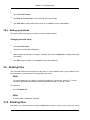
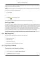
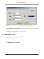
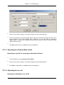
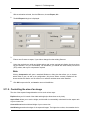

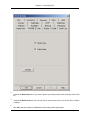
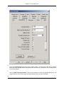
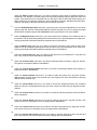
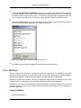
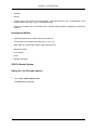
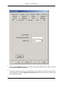
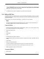

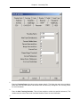
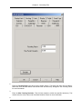

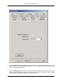
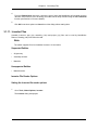
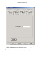
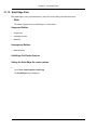
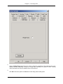
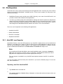
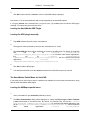
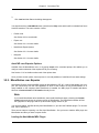
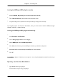
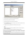
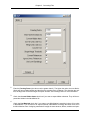
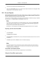
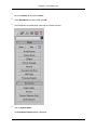
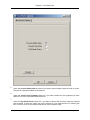
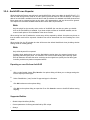
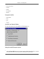
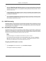
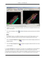
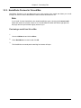
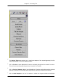

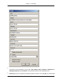
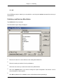
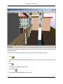
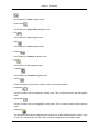

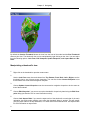

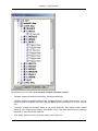
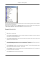
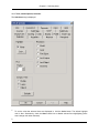
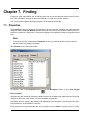
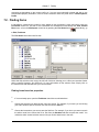
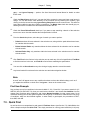
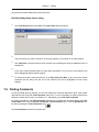
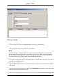

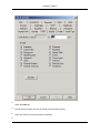
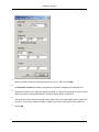
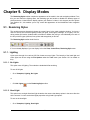
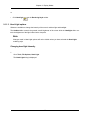
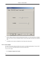
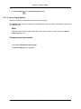
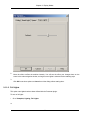
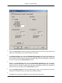
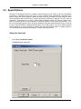
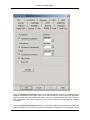
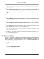
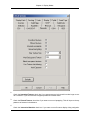
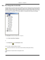
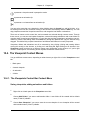
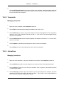
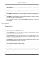
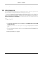
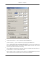
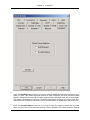


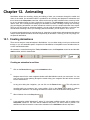
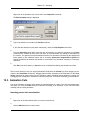
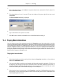
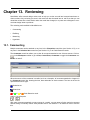
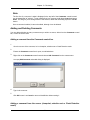
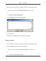
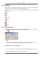
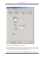
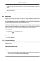
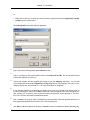
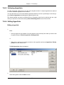
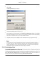
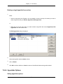
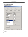
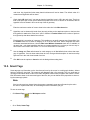
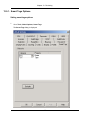
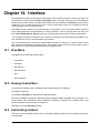
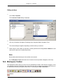
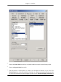
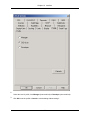
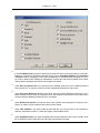
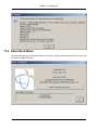
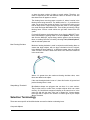


![1 Click the [OK] button.](http://vs1.manualzilla.com/store/data/005894494_1-d1f52ee6fd3b2146a5f252d3f1858c3b-150x150.png)