1
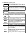
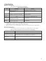
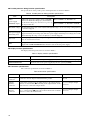
The following document contains information on Cypress products.
FUJITSU MICROELECTRONICS
SUPPORT SYSTEM
SS01-71094-1E
DSU-FR EMULATOR
PSEUDO POWER-ON DEBUG ADAPTER
MB2198-169-E
OPERATION MANUAL
PREFACE
Thank you for purchasing the pseudo power-on debug adapter for the DSU-FR emulator (MB2198169-E).
This product is an adapter that connects between the DSU-FR emulator BGA-224P adapter*1
(MB2198-160-E) that supports the DSU-FR emulator*2 (MB2198-01-E) and DSU-FR emulator
DSU-FR cable (MB2198-10-E), and a header board that is connected to a user system that uses a
Fujitsu MB91470/480 series FR*3 microcontroller and that provides the pseudo power-on debug
function.
This manual describes how to use the pseudo power-on debug adapter for the DSU-FR emulator.
Read this manual carefully before using this product.
Please contact the sales or support representative for details on the mass production and evaluation
MCU models that can be used with this product.
*1 : Referred to below as the "adapter board"
*2 : Referred to below as the "emulator"
*3 : FR, the abbreviation of FUJITSU RISC controller, is a line of products of FUJITSU MICROELECTRONICS Limited.
■ Safe use of this product
This manual contains important information relating to the safe use of this product. Read this manual
before using the product and use the product correctly in accordance with the instructions in this
manual.
In particular, carefully read "■ Caution of the products described in this manual" at the beginning
of this manual and "3. Restrictions" to understand the requirements for safe use of the product before
using it.
After reading the manual, keep it handy for future reference.
■ Product operating environment
This product has an operating temperature range of +5 °C to +35 °C and an operating humidity range
of 20% to 80%. Use the product in an environment that is free of condensation and avoid high temperatures and humidity.
This product consists of a printed circuit board unit without a frame cabinet with exposed electronic
components. Accordingly, do not place other objects on top of the circuit board and do not allow the
metal parts of the unit to come into contact with people or materials that may have a build-up of static
electricity. Similarly, keep any objects that are flammable, likely to cause a short circuit, or cause
any other such problem well away from the unit when the power to the unit is turned on. Keep the
unit horizontal as far as possible and do not use it in locations that are subject to vibration, dust, explosive gases, or other such dangers.
If the unit is used in an environment that does not satisfy the above guidelines, there is a risk of unexpected damage to property or injury to the user or other people in the vicinity. You should also
keep the packaging materials used for shipping the product.
They work well as they are when you transport the product again, for example, if it becomes out of
order and needs to be repaired.
■ Related manuals
Please refer also to the following manuals.
• “DSU-FR EMULATOR MB2198-01-E OPERATION MANUAL”
• “DSU-FR EMULATOR DSU-FR CABLE MB2198-10-E OPERATION MANUAL”
• “DSU-FR EMULATOR BGA-224P ADAPTER MB2198-160-E OPERATION MANUAL”
• “FR60 MB91470/480 Series HARDWARE MANUAL” or “FR60 MB91470/480 Series
DATA SHEET”
• The operation manual of each of the headers
• “SOFTUNE Workbench OPERATION MANUAL”
• “SOFTUNE Workbench USER'S MANUAL”
■ European RoHS compliance
Products with a -E suffix on the part number are European RoHS compliant products.
i
■ Notice on this document
All information included in this document is current as of the date it is issued. Such information is
subject to change without any prior notice.
Please confirm the latest relevant information with the sales representatives.
ii
■ Caution of the products described in this document
The following precautions apply to the product described in this manual.
WARNING
Indicates a potentially hazardous situation which could result in death or serious
injury and/or a fault in the user’s system if the product is not used correctly.
Electric shock,
Damage
Before performing any operation described in this manual, turn off all the power
supplies to the system.
Performing such an operation with the power on may cause an electric shock or
device fault.
Electric shock,
Damage
Once the product has been turned on, do not touch any metal part of it.
Doing so may cause an electric shock or device fault.
CAUTION
Indicates the presence of a hazard that may cause a minor or moderate injury, damages to this product or devices connected to it, or may cause to loose software resources and other properties such as data, if the device is not used appropriately.
Cuts, Damage
Before moving the product, be sure to turn off all the power supplies and unplug the
cables. Watch your step when carrying the product. Do not use the product in an
unstable location such as a place exposed to strong vibration or a sloping surface.
Doing so may cause the product to fall, resulting in an injury or fault.
Cuts
The product contains sharp edges that are left unavoidably exposed, such as jumper plugs.
Handle the product with due care not to get injured with such pointed parts.
Damage
Do not place anything on the product or expose the product to physical shocks. Do
not carry the product after the power has been turned on.
Doing so may cause a malfunction due to overloading or shock.
Damage
Since the product contains many electronic components, keep it away from direct
sunlight, high temperature, and high humidity to prevent condensation. Do not use
or store the product where it is exposed to much dust or a strong magnetic or electric field for an extended period of time.
Inappropriate operating or storage environments may cause a fault.
Damage
Use the product within the ranges given in the specifications.
Operation over the specified ranges may cause a fault.
Damage
To prevent electrostatic breakdown, do not let your finger or other object come into
contact with the metal parts of any of the connectors. Before handling the product,
touch a metal object (such as a door knob) to discharge any static electricity from
your body.
Damage
When turning the power on or off, follow the relevant procedure as described in this
document.
Before turning the power on, in particular, be sure to finish making all the required
connections. Furthermore, be sure to configure and use the product by following the
instructions given in this document.
Using the product incorrectly or inappropriately may cause a fault.
Damage
Always turn the power off before connecting or disconnecting any cables from the
product. When unplugging a cable, unplug the cable by holding the connector part
without pulling on the cable itself. Pulling the cable itself or bending it may expose
or disconnect the cable core, resulting in a fault.
Damage
Because the product has no casing, it is recommended that it be stored in the original packaging. Transporting the product may cause a damage or fault. Therefore,
keep the packaging materials and use them when re-shipping the product.
iii
• The contents of this document are subject to change without notice.
Customers are advised to consult with sales representatives before ordering.
• The information, such as descriptions of function and application circuit examples, in this document are presented solely for the purpose of reference to show examples of operations and uses of FUJITSU MICROELECTRONICS semiconductor device; FUJITSU MICROELECTRONICS does not warrant proper operation of the device with respect to
use based on such information. When you develop equipment incorporating the device based on such information, you
must assume any responsibility arising out of such use of the information. FUJITSU MICROELECTRONICS assumes
no liability for any damages whatsoever arising out of the use of the information.
• Any information in this document, including descriptions of function and schematic diagrams, shall not be construed
as license of the use or exercise of any intellectual property right, such as patent right or copyright, or any other right
of FUJITSU MICROELECTRONICS or any third party or does FUJITSU MICROELECTRONICS warrant non-infringement of any third-party's intellectual property right or other right by using such information. FUJITSU MICROELECTRONICS assumes no liability for any infringement of the intellectual property rights or other rights of third
parties which would result from the use of information contained herein.
• The products described in this document are designed, developed and manufactured as contemplated for general use,
including without limitation, ordinary industrial use, general office use, personal use, and household use, but are not
designed, developed and manufactured as contemplated (1) for use accompanying fatal risks or dangers that, unless
extremely high safety is secured, could have a serious effect to the public, and could lead directly to death, personal
injury, severe physical damage or other loss (i.e., nuclear reaction control in nuclear facility, aircraft flight control, air
traffic control, mass transport control, medical life support system, missile launch control in weapon system), or (2)
for use requiring extremely high reliability (i.e., submersible repeater and artificial satellite).
Please note that FUJITSU MICROELECTRONICS will not be liable against you and/or any third party for any claims
or damages arising in connection with above-mentioned uses of the products.
• Any semiconductor devices have an inherent chance of failure. You must protect against injury, damage or loss from
such failures by incorporating safety design measures into your facility and equipment such as redundancy, fire protection, and prevention of over-current levels and other abnormal operating conditions.
• Exportation/release of any products described in this document may require necessary procedures in accordance with
the regulations of the Foreign Exchange and Foreign Trade Control Law of Japan and/or US export control laws.
• The company names and brand names herein are the trademarks or registered trademarks of their respective owners.
Copyright ©2008 FUJITSU MICROELECTRONICS LIMITED All rights reserved
iv
1. Product Overview
■ Overview
The main features of the adapter are as follows.
• This product is used by connecting it between an adapter board that is fitted with an
MB91FV470 and the header board that corresponds to that adapter board.
• This product supports the pseudo power-on debug function.
• The power supply is provided by 2 systems: the user system power supply (+5V, supplied by
header interface connectors 1 and 2), and the adapter power supply (+16V, supplied by the included AC adapter).
■ Checking the package contents
Before starting to use the adapter, check that the following items are all present.
•
•
•
•
Pseudo power-on debug adapter:
AC adapter:
Operation manual (English version, this manual):
Operation manual (Japanese version):
1
1
1
1
■ Optional products
Table 1 Optional products
Name
Model number
Evaluation MCU
MB91FV470
DSU-FR emulator*
MB2198-01-E
DSU-FR cable
MB2198-10-E
DSU-FR emulator BGA-224P adapter
MB2198-160-E
DSU-FR emulator LQFP-144P header type 9
MB2198-161-E
DSU-FR emulator LQFP-100P header type 7
MB2198-162-E
* : Debugging software, communication cables, etc. need to be purchased separately in order to use
the emulator. Consult the sales or support representative for details.
1
2. Product Description
■ System configuration
Figure 1 shows the system configuration of this product.
DSU-FR emulator unit
Host computer
Generalpurpose
measurement
instrument
AC in
External trigger/
program execution
RS232C, USB, LAN
AC
adapter
DSU-FR cable
DSU-FR emulator unit
Adapter board
pseudo power-on
debug adapter
DC jack
Header board
User system
DSU-FR cable
AC in
AC
adapter
Adapter I/F connector
Header I/F connector
Evaluation
MCU
Connection
Connection
Adapter board
YQPACK
Header board
Connection
Adapter I/F connector
Header I/F connector
NQPACK
Pseudo power-on debug
adapter
User system
Mass-produced
MCU
Figure 1 System configuration
2
■ External view and names of each part
Figure 2 shows the external view of the this product and the names of each part.
104.0 mm
(4) (5)
PON RST
(6)
POWER
OFF
ON
POWER
CN5
(1)
(9)
(10)
RST adj
68.0 mm
GND
H
EML
UVDDE
L
MD0
MD1
MD2
NMIX
USR
CN3
CN1 ADAPTER I/F CN 1
CN4
CN2 ADAPTER I/F CN 2
USER POWER
Vs adj
(3) (7) (8)
19.0 mm
(2)
(11)
(1)
Adapter I/F connector
The connector that connects to the adapter board.
(2)
Header I/F connector
The connector that connects to the header board.
(3)
Trimpot for setting the threshold
voltage
A trimmer potentiometer that sets the threshold value voltage.
The factory default setting is +4V.
(4)
Trimpot for setting the reset
voltage
A trimmer potentiometer that sets the reset voltage.
The factory default setting is +3V.
(5)
Power switch
Switches the power supply of the pseudo power-on debug adapter on or off.
(6)
DC jack
The connector that connects to the AC adapter.
(7)
NMIX control jumper plug
A jumper plug that configures whether the NMIX pin on the evaluation MCU
is connected to the user system or is fixed at "H" on the pseudo power-on
debug adapter.
(8)
Mode control jumper plugs
Jumper plugs that configure the operating mode of the evaluation MCU.
(9)
POWER LED
Indicates whether the power supply of the pseudo power-on debug adapter
is on or off.
(10)
USER POWER LED
Indicates whether the user power supply is on or off.
(11)
Check pin for the user power
supply
A check pin for measuring the user power supply voltage.
Figure 2 External appearance
3
3. Restrictions
■ Hardware restrictions
This section describes restrictions related to the hardware of this product.
• This product isolates the evaluation MCU from the mode lines (MD[2:0]) of the user system.
The mode pin levels of the user system therefore cannot be checked from the emulator.
Take note of the following additional restrictions when the pseudo power-on debug function
is being used.
• When the user system is restarted, the emulator resources (break registers, etc.) are saved.
• Do not change the power switch on the pseudo power-on adapter during a reset (reset signal
from user system, turning off the power during power-on debugging, reset command from the
emulator, etc.).
• In order to implement the pseudo power-on debug function, the reset signal from the user system is delayed by a maximum of 40ns on the pseudo power-on debug adapter. Other restrictions may apply to the reset signal when the emulator is being used. Refer to the operation
manual for the adapter or emulator for details.
• Because the MCU power supply does not fall below VS, if a voltage less than or equal to VS
is applied to UVDDE, the voltage level of VOH of the MCU will be calculated from VS, and
the user system may be exposed to electrical stress. Furthermore, the VIH level of the MCU
will also be greater than the original level, and the MCU might not accept "H" inputs.
• The user power supply monitoring function cannot be used on the emulator. However, although
this product is equipped with a UVDDE indicator LED, this cannot be used to detect transient
power stoppages (the emulator can detect user resets due to transient power stoppages).
• The emulator treats disconnection of the user power supply as input of a user reset.
• The power supply of the user system can only be disconnected when the evaluation MCU is
in trace mode (executing). The operation is not guaranteed if the power supply is disconnected
while in emulation mode. After the power is turned back on, the MCU will start in trace mode
and program execution will begin with the reset sequence of the user system.
• If the power supply is disconnected during a break, the MCU does not reset because the user
reset is masked by the emulator. The MCU output pins therefore all maintain the same output
state, and there is a risk that the user system will be damaged. To prevent this, reset the MCU
using the emulator reset command before turning off the power.
• If UVDDE drops below the monitor reference voltage while in stop mode, a reset is applied
and the oscillator circuit begins oscillating. The MCU can therefore be started in this situation
simply by returning UVDDE to the operating voltage without applying a user reset or generating an interrupt. Furthermore, an interrupt cannot be used to recover from stop mode in this
situation because the reset has already been applied.
• Port pins on the user system are required to maintain a weak “L” level when the user power
supply is off (required to be equivalent to a pull-down resistance below VIL/IIL of the MCU).
■ Software restrictions
This section describes restrictions related to the software of this product.
Take note of the following restrictions when the pseudo power-on debug function is being used.
• Because a user reset is asserted when the emulator power supply is turned on, the monitor is
not ready until the user system power supply has powered up.
• From the point of view of the emulator, all disconnections of the user system power supply
are viewed as user reset inputs. The operational specifications of the user resets are as noted.
• Software breakpoints cannot be used on memory in the user system during power-on debugging.
4
4. Connections
■ Connecting to the adapter board
Connect the adapter interface connector of the pseudo power-on debug adapter to the header interface connector on the adapter board.
Adapter board
Header I/F
connector2
Header I/F
connector1
Adapter I/F
connector2
Adapter I/F
connector1
Pseudo power-on debug adapter
Figure 3 Connecting the adapter board
■ Connecting to the header board
Connect the header interface connector of the pseudo power-on debug adapter to the adapter interface connector on the header board. Refer to the operation manuals of each of the header boards for
details on connecting the header board to the user system.
Pseudo power-on debug adapter
Header I/F
connector2
Adapter I/F
connector2
Header I/F
connector1
Adapter I/F
connector1
Header board
User system
Figure 4 Connecting the header board
Notes: • Turn off the power before connecting and disconnecting the board.
• When removing the board, apply force evenly across the board without concentrating on a single
point to remove the board.
5
5. Operation
5.1 Configuring the mode pins of the evaluation MCU
■ Configuring the jumper plugs for setting the mode of the evaluation MCU
The factory default settings of the jumper plugs for setting the mode pins of the evaluation MCU are
shown in Figure 5, and the jumper plug setting specifications for the mode pin connections of the
evaluation MCU are shown in Table 2.
BVDDE
[NMIX]
[MD0]
[MD1]
[MD2]
L
H
Evaluation MCU MD0
Evaluation MCU MD1
Evaluation MCU MD2
GND
Figure 5 Evaluation MCU mode pin setting circuit (factory default settings)
Table 2 Jumper plug settings for configuring the evaluation MCU mode pins
Jumper plug setting
MCU mode name
MD2
MD1
MD0
Internal ROM mode vector
L
L
L
External ROM mode vector
L
L
H
Notes: • Settings other than those shown in Table 2 are not allowed.
• The pseudo power-on debug adapter board isolates the mode pins from the user system. Be careful
because these MCU mode pins form the mode pin data of the evaluation MCU.
• Refer to the data sheet of the evaluation MCU for details on each of the MCU modes.
6
5.2 Configuring the NMIX pin of the evaluation MCU
■ Configuring the jumper plugs for setting the NMIX pin of the evaluation MCU
The NMIX pin of the evaluation MCU can be configured to be connected to the user system or to be
fixed at "H" on the pseudo power-on debug adapter. The factory default setting of the jumper plug
for setting the NMIX pin of the evaluation MCU are shown in Figure 6, and the jumper plug setting
specifications for the NMIX pin connection of the evaluation MCU are shown in Table 3.
BVDDE
10 kΩ
USR
User system NMIX
[NMIX]
EML
Evaluation MCU NMIX
[MD0]
[MD1]
[MD2]
Figure 6 NMIX pin setting circuit
Table 3 Jumper plug settings for configuring the evaluation MCU NMIX pin
Jumper plug name
Setting
NMIX connection
USR
The NMIX pin of the evaluation MCU is connected from
the user system.
EML
The NMIX pin of the evaluation MCU is fixed at “H” on
the pseudo power-on debug adapter.
NMIX
7
5.3 Configuring the power supply threshold voltage
The power supply threshold voltage is preset to +4V when the product is shipped. Follow the instructions below “■ Changing the power supply threshold voltage” to change the power supply threshold
voltage.
■ Changing the power supply threshold voltage
[Preparation]
Use the following procedure to prepare to adjust the power supply threshold voltage (VS).
1. Connect this product to the adapter board without the evaluation MCU mounted, and remove all
other cables.
2. Connect the included AC adapter to the power supply connector on the pseudo power-on debug
adapter such that the power is able to be supplied.
3. Connect a voltage meter between the VCC and GND pins on the adapter board such that VS can
be measured from the VCC pin. Refer to Figure 7 for the positions of the VCC and GND check
pins.
[Configuration]
After the preparations are finished, use the following procedure to adjust the power supply threshold
voltage (VS).
1. Turn on the power switch of the pseudo power-on debug adapter.
2. Rotate the trimpot for setting the threshold voltage to adjust VS to the desired voltage. Turn the
knob on the trimpot to the right to reduce the value of VS and to the left to increase the value.
Refer to Figure 7 for the position of the trimpot for setting the threshold voltage.
3. Turn off the power switch of the pseudo power-on debug adapter.
Note : The threshold voltage (VS) and the reset voltage (Vr) are independent parameters that are not related.
Although it is possible to change only one of these settings, make sure that the settings do not conflict
with the function specifications.
Power supply
measurement pins
Adapter board ↓
CN5
TP4
POWER
GND
RST adj
TP1
OFF
ON
POWER
PON RST
VCC
MD0
MD1
MD2
ON
GND
Vs adj
1 2 3 4 5 6
L
USR
UVDDE
TP3
GND
H
NMIX
EML
USER POWER
VCC
TP2
Trimpot for setting
the threshold voltage
Pseudo power-on debug adapter ↑
Figure 7 Positions of the measurement and control components
Note : Because the distance between the VCC and GND pins on the adapter board is small, there is a risk of
a short circuit if the leads of the voltage meter come into contact with each other. If the pins are in contact when the voltage meter is connected, try measuring between VCC (TP1) and GND (TP3), or between VCC (TP2) and GND (TP4).
8
5.4 Configuring the user power supply monitoring reset voltage
The user power supply monitoring reset voltage is preset to +3V when the product is shipped. Follow
the instructions in “■ Configuring the user power supply monitoring reset voltage” below to change
the setting of the user power supply monitoring reset voltage.
■ Configuring the user power supply monitoring reset voltage
[Preparation]
Use the following procedure to prepare to adjust the user power supply monitoring reset voltage (Vr).
1. Remove all of the cables such that there are no devices connected to this product.
2. Connect the included AC adapter to the power supply connector on the pseudo power-on debug
adapter such that the power is able to be supplied.
3. Connect a DC variable power supply unit to the user power supply check pin. Refer to Figure 8
for the positions of the user power supply check pin and GND check pin.
[Configuration]
After the preparations are finished, use the following procedure to adjust the user power supply monitoring reset voltage (Vr).
1. Turn on the power switch of the pseudo power-on debug adapter.
2. Turn on the power to the DC variable power supply unit, and set the voltage to the desired value
of Vr.
3. Rotate the knob on the trimpot for setting the reset voltage all the way to the right to set Vr to the
maximum value. Check that the "USER POWER" LED is off at this time. Refer to Figure 8 for
the position of the trimpot for setting the reset voltage.
4. Gradually turn the knob on the trimpot to the left to reduce the value of Vr. Continue turning the
knob until the “USER POWER” LED lights up. The voltage between the UVDDE and GND pins
at this time is the user power supply monitoring reset voltage.
5. Turn off the power switch of the pseudo power-on debug adapter.
Note : The threshold voltage (VS) and the reset voltage (Vr) are independent parameters that are not related.
Although it is possible to change only one of these settings, make sure that the settings do not conflict
with the function specifications.
Trimpot for setting
the reset voltage
PON RST
POWER
OFF
ON
POWER
CN5
RST adj
GND
H
EML
UVDDE
L
MD0
MD1
MD2
NMIX
USR
CN3
CN1 ADAPTER I/F CN 1
CN4
Vs adj
CN2 ADAPTER I/F CN 2
USER POWER
User power supply
check pins
Figure 8 Locations for connecting the DC variable power supply unit
9
5.5 Pseudo power-on debug function
Use the following procedure to use the pseudo power-on debug function. Refer to “5.6 Power-on and
shutdown sequence” for details on the power-on and off sequence.
■ Sequence for using the pseudo power-on debug function
[Starting debugging]
1. Follow the power-on sequence to turn on the power to the emulator, pseudo power-on debug
adapter, and user system.
2. Configure the various settings in the emulator debugger
3. Run the “GO” command on the emulator
[Pseudo power-on debugging]
The pseudo power-on debug function can be operated by simply turning off and on the user power
supply, and power-on debugging can be performed by the emulator.
[Stopping debugging]
1. Perform the emulator reset command (resets the evaluation MCU)
2. Follow the shutdown sequence to turn off the power to the user system, pseudo power-on debug
adapter, and emulator.
Note : If the power supply of the user system is turned off, the MCU does not reset because the user reset is
masked by the emulator. The MCU output pins therefore all maintain the same output state, and there
is a risk that the user system will be damaged. To prevent this, reset the MCU using the emulator reset
command before turning off the power.
10
5.6 Power-on and shutdown sequences
■ Power-on sequence
To turn the power on, finish making all the required connections and then follow the procedure
shown in Figure 9.
To turn on the emulator, press the power switch on the back of the emulator. The power switch remains depressed.
Immediately after the emulator is shipped, an initialization operation (monitor loading) is required
before the power is turned on to the user system. For information about how to initialize the emulator, refer to “SOFTUNE Workbench operations manual”.
Turn on the host computer
Turn on the emulator
The POWER LED on the emulator lights up
Run “SOFTUNE Workbench”
Run “Emulator Debugger”
Has the emulator
been initialized?
YES
NO
Perform the emulator initialization operation
Check that the dialog box is displayed
(see Figure 10)
Turn on the power to the pseudo
power-on debug adapter
The POWER LED on the pseudo
power-on debug adapter lights up
Turn on the user system
The USER POWER LED on the pseudo
power-on debug adapter lights up
Click “OK” in the displayed dialog box
Figure 9 Power-on procedure
11
Figure 10 Dialog display
Note : When the user system is turned on, the “USER POWER” LED on the adapter board lights up. If it does
not light up when the power is turned on, immediately turn off the power supply of the entire system,
check for any incorrect connections and resolve the problem before turning on the system again.
■ Shutdown sequence
To shut down the system, follow the procedure shown in Figure 11.
To turn off the emulator, press and release the power switch on the back of the emulator. This returns
the depressed switch to the OFF (raised) state.
Exit “Emulator debugger”
Turn off the user system
The USER POWER LED on the pseudo
power-on debug adapter goes out
Turn off the power to the
pseudo power-on debug adapter
The POWER LED on the pseudo
power-on debug adapter goes out
Turn off the emulator
The POWER LED on the emulator goes out
Turn off the host computer (as needed)
Figure 11 Shutdown procedure
12
6. Specifications
■ General specifications
Table 4 lists the general specifications of the adapter.
Table 4 General specifications
Item
Description
DCIN: DC16V, Max: 2.5A
Supplied by the included AC adapter*1
UVDDE: DC5V*2
Supplied by the user system via the header interface
connector
68mm (W) × 104mm (D) × 19mm (H)
Including protrusions
Power supply
External dimensions
Remarks
Weight
38.6g
The pseudo power-on debug adapter itself
Temperature*3
During operation: +5 °C to +35 °C
When stored: 0 °C to +80 °C
No condensation
Humidity
During operation: 20% to 80%
When stored: 20% to 80%
No condensation
*1 : The AC adapter can be purchased as a retail item (model number: RC45-16B, Futaba Electric Co Ltd).
*2 : UVDDE is the power supply for the evaluation MCU supplied by the user system. Refer to the data sheet for the
evaluation MCU for details on supplying power to the evaluation MCU.
*3 : Refer to the data sheet for the evaluation MCU for details on the temperature range of the evaluation MCU.
■ Function specifications
The functional specifications of the pseudo power-on debug adapter are shown in Table 5.
Table 5 Functional specifications of the pseudo power-on debug adapter
Item
Description
Adapter ⇔ Header connection
Functions as an adapter that connects the adapter board to each of the headers.
Pseudo power-on debugging
Equipped with the pseudo power-on debug function that can debug program execution
from immediately after the evaluation MCU power is turned on.
Jumper plugs
Equipped with jumper plugs that configure various settings on the pseudo power-on
debug adapter.
DC jack
Supplies power to the pseudo power-on debug adapter from the included AC adapter.
13
■ Pseudo power-on debug function specifications
The specifications of the pseudo power-on debug function are shown in Table 6.
Table 6 Pseudo power-on debug function specifications
Item
Description
MCU
power supply
(BVDDE) output
Follows the user power supply voltage (UVDDE)
When UVDDE ≤ VS, BVDDE = VS
down to the threshold voltage (VS), and maintains
the threshold voltage (VS) when the user power supWhen UVDDE > VS, BVDDE = UVDDE
ply drops below this.
Threshold voltage
The threshold voltage (VS) can be adjusted through the range 3.3V to 4.3V using a trimpot (Preset
to 4V when shipped).
Outputs a reset signal when the user power supply voltage (UVDDE) drops below the user power
User power supply
supply monitoring reset voltage (Vr). The user power supply monitoring reset voltage (Vr) can be
monitoring reset
adjusted through the range 1.7V to 5V (Preset to 3V when shipped).
User reset
Reset signals generated by the user power supply monitoring circuit and signals input from the user
reset are treated as user resets.
LED
Equipped with a POWER LED that shows the state of the pseudo power-on debug adapter power
supply and a USER POWER LED that shows the state of the user power supply.
■ Display function specifications
The display function specifications are shown in Table 7.
Table 7 Display function specifications
Item
Description
POWER LED
Shows the state of the power supply (DCIN) of the pseudo power-on debug adapter.
USER POWER LED
Shows the state of the power supplied by the user system (UVDDE).
■ Connector specifications
The connector specifications are shown in Table 8.
Table 8 Connector specifications
Item
Description
Remarks
Power supply
connector
Connects to the AC adapter included with the product.
Adapter
interface
connector
Connects the pseudo power-on debug adapter to the adapter board.
Set of 2 × 120-pin straight
Refer to “4. Connections, ■ Connecting to the adapter board” for deconnectors
tails on how to connect the adapter board.
Header
interface
connector
Connects the pseudo power-on debug adapter to the header board. ReSet of 2 × 120-pin straight
fer to “4. Connections, ■ Connecting to the header board” for details
connectors
on how to connect the header board.
14
DC jack
SS01-71094-1E
FUJITSU MICROELECTRONICS • SUPPORT SYSTEM
DSU-FR EMULATOR
PSEUDO POWER-ON DEBUG ADAPTER
MB2198-169-E
OPERATION MANUAL
June 2008 the first edition
Published FUJITSU MICROELECTRONICS LIMITED
Edited
Business & Media Promotion Dept.