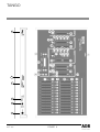
1
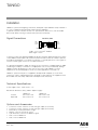
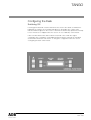
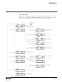
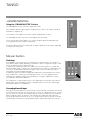
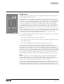
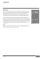
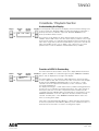
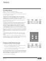
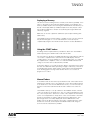
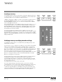
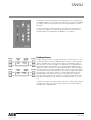
TANGO
Instruction
Manual
Page 1
Rev. : 003
TANGO
Summary
Delivery - Unpacking
3
Generalities - Safety
Important Notice for Power Cables
3
3
Installation
Signal Connections
Technical Specifications
4
4
4
Configuring the Desk
Setting up the configuration
The Help Text
7
8
9
«GRAND MASTER»
Using the "GRAND MASTER" Section
Manual Section
Flash Keys
Generating Manual Output
Single Preset
Dual Preset
10
10
10
10
10
11
12
Crossfade / Playback Section
Understanding the Display
Function of LED's & Preview Key
Recording a Memory
Assigning crossfade Times to Memories
Replaying a Memory
Using the START button
Manual Faders
Inserting a memory
Modifying a memory or modifying Intensities on Stage
Deleting a Memory
13
13
13
14
14
15
15
15
16
16
17
The Effect Section
Channel Button
Speed Control
START/STEP Button
Level Control
ON/OFF Button
Direction BUTTON
Selecting a chase pattern via the button Mode
Browsing through pre-selected chase pattern via the button MODE
Select a Chase Pattern through the Menu
18
18
18
19
19
19
19
19
20
20
Patching the DMX Output
22
Remote Control Option
23
Working with Submasters
24
Analogue Output Option
Analogue Output Card Installation Instruction
26
26
In case of Difficulty
27
Controls, Indicators and Connectors
28
Page 2
Rev. : 003
TANGO
Delivery - Unpacking
Upon delivery of your equipment, open the packaging carefully and examine the material.
If you observe any damage, contact the shipping company immediately, and have your
complaint duly recorded. You may rest assured that your equipment left the factory in perfect
condition.
Check whether what you have received is in conformity with the delivery notice, and whether
the notice is in conformity with your order.
In the event of any error, contact your shipper immediately to clarify the situation and receive
full satisfaction.
If you find nothing wrong, replace the material in the packing and store it in a warm place,
away from dust and humidity, while awaiting final installation.
Never leave the material on the worksite under any circumstance.
Generalities - Safety
The equipment is built in accordance with European safety standards and requires
imperatively a safety earth connection in compliance with local regulations.
To prevent any risk of electric shock, do not remove any cover or part of the enclosure.
Access to internal parts is not required for normal operation.
Refer servicing to skilled and trained service personnel exclusively.
Disconnect from the power supply prior to opening for inspection or service.
WARNING ! LETHAL VOLTAGES ARE PRESENT INSIDE
Connection to an inappropriate power source may irreversibly damage the equipment, it is
the user’s responsibility to use the equipment for its intended purpose and to check the
equipment connected to it.
To obtain full benefits of the safety measures, the equipment shall be installed and serviced
by skilled and trained personnel exclusively.
Don't make any modification to the equipment.
ADB shall not accept any liability for material damages or injuries which may result from
unauthorised modifications.
Important Notice for Power Cables
Power supply cables and connectors are an important part of your equipment and contribute
to its safety.
• always use an isolator or main circuit-breaker, or main fuses to interrupt the link; never
pull on the cable
• do not damage the cable nor the connectors in any way, check them at each installation
or at regular intervals in a permanent installation
• do not tie together power supply cables and signal cables
Page 3
Rev. : 003
TANGO
Installation
TANGO is a professional lighting control desk, developed as per EN60950 safety standard. It
is a class 1 equipment designed and manufactured to EN60950.
To prevent any risk of electric shock do not open the desk, there are no user serviceable
parts inside. Refer servicing to trained service personnel exclusively.
Signal Connections
DMX512/1990
GND
1
DATA - 2
DATA + 3
4
5
O
O
O
O
O
O 1 GND
O 2 DATA O 3 DATA +
O4
O5
XLR5-MX
dimmer dependent
2
Cable : 2 x 2 x 0,34 mm shielded
Max. length : 250 m
To enhance safety and operating reliability this product has been fitted with galvanic isolation
on the DMX512/1990 output. This isolation has been tested for 500V dc in order to prevent
grounding loop problems or to transfer low voltages occasionally present on some signals to
controls or other signal connectors accessible to the user.
It is absolutely forbidden to apply any voltage to the connections of TANGO (Remote, DMX
and Analogue outputs). Connections to inappropriate sources may inadvertently damage
TANGO and may be dangerous to the user. It is the user's responsibility to use the
equipment for it's intended purpose and to check the equipement connected to it.
TANGO is a professional piece of equipment developed with simplicity of use in mind.
However, in order to fully benefit from the designed in safety features, the equipment shall
be installed and serviced by skilled and trained personnel exclusively.
Technical Specifications
Power supply : 220V - 240V, 50 Hz ± 1 %.
Mechanical dimensions (mm) (width x depth x height) :
Packed
Unpacked
TANGO 24
650 x 340 x 130
620 x 315 x 118
TANGO 48
860 x 340 x 130
815 x 315 x 118
Options and Accessories
•
•
•
•
•
•
•
Conversion card for 370uA or 0/+10V analogue output (24 channels).
Conversion card for 370uA or 0/+10V analogue output (48 channels).
64K memory card for permanent storage.
DE09-P connector for remote control.
5 pin XLR male connector for DMX512 signal.
Dust cover for TANGO 24.
Dust cover for TANGO 48.
Page 4
Rev. : 003
TANGO
Unpacking the Desk
After removing the desk from it's box, check that the following items are included :
•
•
•
•
1 TANGO desk
1 User manual (this document)
1 Power supply cable
1 * 5 pin XLR male connector for DMX512/1990 signal
If any of the previous items are missing contact your supplier immediately. Retain the box
and packing material for any future transportation or storage of the desk.
Precautions
WARNING
To prevent fire or shock hazard, do not expose these
units to rain or moisture.
Caution
Disconnect the mains plug from the supply socket when not in use.
Should the power lead inadvertently become detached from the desk, the current state of all
settings will be maintained, until normal power is resumed.
Avoid using the desk under the following conditions :
•
Extremely hot, cold or humid places
Limits:
Ambient temperature
: 0 to 40 °C
Storage
: - 10 to 50 °C
Maximum gradient
: 5 °C per hour
Humidity
: 30 % to 70 % RH without condensation.
•
Dusty places
•
Be careful of moisture condensation.
• Avoid using the desk immetiately after moving from a cold place to a warm
place or soon after heating a room which was cold.
•
Handle the desk carefully.
•
Do not place anything heavy on the desk.
•
Do not place anything which could spill and cause problems on or near the desk.
Page 5
Rev. : 003
TANGO
Connecting to the back panel
The only connection required to operate the desk is for the power supply cable to be plugged
into the power socket on the back panel, and the power plug to be connected to a suitable
mains outlet. However if any output is needed then a suitable cable needs to be linked from
the DMX512/1990 output socket to a recommended DMX512/1990 controlled dimmer unit.
Page 6
Rev. : 003
TANGO
Configuring the Desk
Switching ON
Powering up the desk will cause the internal function check to be carried out. While this is
happening the software version number will appear on the display. The current status
indicators will then appear on the screen to show that the desk is fully operational and ready
for use. If this does not happen refer to the section "in case of difficulty" of this manual.
If this is the first time that the desk has been used, it will come on with the original
configuration.This configuartion is remembered when the desk is switched off, and will be
used next time the desk is switched on. To change the configuration refer to the section
"Configuring the desk" of this manual.
Page 7
Rev. : 003
TANGO
Setting up the configuration
The desk can be set up with a number of different parameters, depending on the current
requirements of the operator. These parameters are :
• Writing to and from the memory card
• The patching of desk outputs to dimmer inputs
• Deleting memories
• Single or dual preset
• Setting the Effect section chase patterns
• Accessing the HELP text
• Remaining / free memories
• The contrast of the display
• Resetting the desk (Cold Booting or Cold Start)
• Working with submasters
The configuration dialogue for the desk is entered by pressing the «MENU» key. At this point
the display changes to offer a range of options which may be either accepted or modified as
required. If at any point a QUIT or SAVE key is pressed the configuration menu is exited and
the display returns to normal.
AUX
MENU
To change two or more parameters the «MENU» key must be pressed again to re-enter the
configuration mode. Pressing the "MENU" button at any time whilst in the configuration
menu's will exit at that point and ignore any modification made.
The first press of the "MENU" key gives the opening menu screen. Each option is adjacent
to one for the «NEXT» and «LAST» keys. Pressing the corresponding key either changes
the setting, or offers another menu screen from which further options are available. Figure 1
shows the sequence of options and screens that makes up the full configuration options.
The patching of the DMX outputs is a slightly more complex procedure which is covered in
detail in the Patching the DMX output section of this manual.
Page 8
Rev. : 003
TANGO
The Help Text
The help text is available via a MENU option (see figure 1). To use it, simply select the HELP
option and a scrolling topic list will then be displayed. Selecting a topic displays a scrolling
description. Use the RECORD LAST and NEXT buttons to scroll through the text.
Select Menu
Exit menu without saving
Exit menu without saving
< QUIT
< MORE
to card >
from card >
< QUIT
< MORE
Patch >
delete >
Write data onto memory card
Read data from memory card
Exit menu without saving
Exit menu without saving
Save selection
and increment dimmer N°
Exit menu without saving
Exit menu without saving
Delete memory range slect & exit
Exit menu without saving
Exit menu without saving
< QUIT
< MORE
< QUIT
< MORE
1 preset >
2 preset >
eff mode >
help >
< QUIT
< create
< QUIT
< CHANGE
default >
clear >
Dim <01>▲
Ch01▼
< BACK
< NEXT
Dim 01▲
Ch<03>▼
< QUIT
< NEXT
delete▲
<012>▼
< QUIT
< YES
Del <012>▲
to<017>▼
Select default patch & exit
Clear all patch & exit
Increase dimmer N°
Decrease dimmer N°
Increase channel N°
Decrease channel N°
Increase "from" memory N°
Decrease "from" memory N°
Increase "to" memory N°
Decrease "to" memory N°
Select single preset & exit set-up
Select dual preset & exit set-up
Exit menu without saving
save selection & exit
< QUIT
< SAVE
Pot▲
26▼
Increase effect pattern N°
Decrease effect pattern N°
Help functions
Exit menu without saving
< QUIT
< MORE
free mem >
contrast >
Exit menu without saving
< QUIT
= 1000
free mem
(100 %)
Exit menu without saving
< QUIT
< SAVE
contrast▲
▼
save selection & exit
Exit menu without saving
< QUIT
< MORE
< QUIT
< MORE
reset >
subm. YES >
subm. NO >
Increase contrast level
Decrease contrast level
Exit menu & completely reset desk
Select submaster mode
Deselect submaster mode
Page 9
Rev. : 003
TANGO
«GRAND MASTER»
Using the "GRAND MASTER" Section
The Grand Master section controls the output of the desk.
If the «ON/OFF» button is pressed then all output from the desk is off, and the LED above
the button is off (Black-out).
A second press of the button restores the output, and illuminates the LED.
The Grand Master fader controls the overall output level of the desk.
In it's lowest position (0) the output is off, as if the «ON/OFF» button had been pressed.
In it's highest position (10) output is at maximum.
Any position beween these two will provide an output of between 0% and 100% depending
on the position of the fader.
Manual Section
Flash Keys
Each MANUAL section fader has associated with it a «FLASH» button. The operation of
these buttons differs slightly depending on whether the desk is configured as single or dual
Preset, in submaster or non-submaster mode.
In single Preset each button flashes the output of that channel, and the associated LED,
above the button, lights. In dual Preset each channel has two faders associated with it, and
so has two «FLASH» button will flash the output of that channel, and both the LED's in
Preset bank A and Preset bank B will light.
In submaster mode (see chapter 'Working with submasters'), the flash buttons are used to
flash a submaster's contents (use of flash buttons alone), to record a lighting cue into a
submaster (in combination with the key 'RECORD') or to modify a submaster's contents
(in combination with the key 'MODIFY')
The output from a «FLASH» button press is only dependent on the position of the Grand
Master fader, on the Grand Master section's «ON/OFF» button, and on the coresponding
Preset Master Button A or B (ON/OFF).
Generating Manual Output
Each group of Preset faders has a Preset master control fader and on/off button. The master
for Preset B works in reverse of that for Preset A, i.e. 100% is at the bottom and 0% is at the
top of its travel, for Preset B. The «ON/OFF» buttons work in a similar fashion to the Grand
Master «ON/OFF» button, in that they control whether the output from their respective
Preset group is blacked out (LED off) or not. In single Preset mode the Preset B on/off LED
is permanently off and the associated «ON/OFF» button and master fader have no function.
Page 10
Rev. : 003
TANGO
Single Preset
In single Preset mode the number of channels available in the manual section will be twice the
number available in dual Preset mode.
Assuming that all the Preset faders are at the bottom of their travel and that the Preset A
master fader is set to a value above 0 and that the «ON/OFF» button has not been pressed,
i.e. the LED is on. Also that the Grand Master fader is above 0 and it's associated «ON/OFF»
button has not been pressed. Moving a Preset fader off 0 will produce an output on that
channel. If a dimmer unit is connected to the output the lamp on that channel will light.
Increasing the level of the Preset fader will increase the light level of the lamp. Depending
on the PREVIEW mode selected, once the output level increases above a 5% the LED
below that Preset fader will light, refer to the Function of LED's & preview key section of this
manual.
Once the output level increases above a 5% the LED below the Preset fader will light. Also if
the Preset master fader is over 5% the Preset A bank LED will light to show that the Preset is
active. Moving more Preset faders will light more lamps on the corresponding output
channels as well as the LED's below the faders on the desk.
Once a display of illuminated lamps has been created on the output the level of these lamps
may be varied in several ways.
•
By moving each individual fader to vary it's output level.
•
By changing the position of the Preset master fader A to after the output level of all the
active Preset channels.
•
By moving the Grand Master fader to change the output level of the desk.
The action of the master fader is governed by the setting of the manual timer control.
If we consider the movement of the master fader, and call the start position posn. A and the
end position posn. B. If the timer is set to 0 then the output will change in time with the
movement of the master fader. If the timer is set to anything else then the output will change
from the posn. A to posn. B fader setting's in the time set. Whilst the output is still changing
from one setting to the other the RUN A LED above the timer will flash to show that the fade
is still in progress. If the master fader is moved again, say to posn. C, whilst a fade is in
progress then the fade restarts, at the new time setting (if changed), from posn. B to posn. C.
Note :
If the manual timer control is moved whilst a fade is in progress then the fade will restart
from it's current position to it's final position but will take into account the percentage
complete of the current fade i.e. If the fade was 50% complete and the manual timer was
moved to 18 seconds the fade would take a further 9 seconds to complete.
At any stage the output may be blacked out by using either of the «ON/OFF» buttons, in the
maunal Preset A, manual Preset B or the Grand Master sections. A Blackout state may also
be achieved by moving either master fader to 0. If a blackout is initiated, by pressing one of
the relevant «ON/OFF» buttons, whilst a fade is in progress, the fade will continue to it's end.
Page 11
Rev. : 003
TANGO
Dual Preset
Dual Presets allow for the creation of two output settings on two different banks of faders,
Preset A and Preset B. Either or both presets may be output from the desk with the highest
value of each channel taking precedence.The active Preset(s) are shown by illuminating the
corresponding LED. The Preset fader LED's show various states, depending on the
PREVIEW mode selected, refer to the Function of LED's & preview key section of this
manual. Either Preset may be blacked out using the corresponding «ON/OFF» button and
the output level of each Preset is determined by the two master faders, labelled A and B.
Assume an output pattern has been created on both banks of faders and that Preset A is
currently active, i.e. both master faders are at the top of their travel, and the timer control is
set to 10 secs. A dip-less cross fade can be made from Preset A to Preset B simply by sliding
both master faders together from the top to the bottom of their travel. Preset A will fade out
as Preset B fades in. The total fade will take 10 seconds and during this time both the RUN A
and RUN B LED's above timer control will flash showing a fade is in progress. Once complete
a new output pattern may be created on the Preset A bank of faders and the process
reversed, i.e. the master faders moved from the bottom to the top of their travel, to fade the
new pattern in.
Note :
A dip-less cross fade will constantly compare the value of the two faders relating to each
channel. The highest value will always take precedence, i.e. the output value will never fall
below that of the initial fader value.(dipless crossfade)
Page 12
Rev. : 003
TANGO
Crossfade / Playback Section
Understanding the Display
000
I
000
I ∆000 %
In normal operation the top line of the display shows information relating to the
storing of memories. RECORD TIME is the time that will be recorded with a
memory when the record button is pressed. RECORD MEMORY is the
memory number it will be stored to.
The lower line of the display has three seperate windows known as STAGE,
PRESET and XF TIME. These show the current memory number on the stage
and in Preset and the cross fade time that will fade in the Preset memory and
fade out the stage memory when the START button is pressed. To the left and
right of the display are two sets of «NEXT» and « LAST» keys. In normal
operation these scroll the PRESET and RECORD memory numbers.
Function of LEDS & Preview Key
The LED's below the Preset faders can be set to display different information.
The options available are scrolled through using the «MEMORY PREVIEW»
button, and are displayed on the right of the display.
PREVIEW MEM 049
TIME 0 : 05
The initial setting is to show the desk output mimicked on the Preset LED's,
i.e. if the output for that desk channel is more than 5% then the LED will light.
By pressing the «MEMORY PREVIEW» button once the LED's can be
selected to show the output from the Memory section of the desk, called
Crossfade and playback.
The display will change to confirm which memory number is being previewed,
and also the cross fade time stored with that memory. The active channels of
that memory will show as lit LEDs. The preview memory number may be
scrolled by using the PRESET NEXT and LAST buttons. Another press of the
"MEMORY PREVIEW" shows the output from the Effect number currently
selected. A further press of the «MEMORY PREVIEW» button returns the
LED's to showing desk output.
If the LED's were previewing either Memory or Effect then pressing any button
in the Preset (other than a flash button), Memory, Chase or Master sections of
the desk will cause the LED's to revert to showing desk output.
Page 13
Rev. : 003
TANGO
Recording a Memory
TANGO can store up to 200 memories in total.
Modification includes storing, deleting, modifying and inserting.
Note that memory 000 is a blackout state, i.e. no output from the desk, and
cannot be modified or over written.
«RECORD» will record the current output of the desk into the memory
number shown in the RECORD MEMORY window on the display. This
number may be set to any whole number between 001 and 999 using the
RECORD NEXT and LAST buttons to the right of the display.
If the number displayed has already been recorded then the RECORD
MEMORY window will NOT flash.
000
I
000
I ∆000 %
The output of the desk may be created using a combination of the manual
Preset faders, the Effect section and any existing memory. When the
«RECORD» button is pressed the output is recorded into the memory
number in the RECORD MEMORY window. If that memory number was
previously recorded (the number was not flashing) then confirmation is
requested before the old memory is over written. As the memory is stored
the RECORD MEMORY window changes to show the next memory number.
When you record a memory for the first time, the time given by the MANUAL
TIMER fader is taken into account and stored in the memory. If that memory
number has been previously recorded, the previous time of the memory is
kept.
By pressing RECORD NEXT and RECORD LAST together, the memory
displayed in the PRESET window is copied into the RECORD MEMORY
window.
Replaying memories is covered in the Replaying a memory section of this
manual. Should it be necessary to change the contents of any memory then
refer to the modifying a memory section of this manual.
Assigning crossfade Times to Memories
To assign a time to a memory, you have two possibilities.
•
Either you use the MANUAL TIMER fader, if the memory has not been
recorded yet, as described in the previous section.
•
or you want to modify the time after having recorded the memory, in
which case you follow the following procedure :
Pressing the «TIME» button will allow a cross fade time to be assigned to the
memory number currently shown in the PRESET window. Using the PRESET
NEXT and LAST buttons will change the minutes figure. Using the RECORD
NEXT and LAST buttons changes the seconds.
To record the time, press «TIME» again.
Page 14
Rev. : 003
▲TIME
▼min00
007▲
05sec▼
TANGO
Replaying a Memory
This function involves fading from the currently active memory (STAGE). If one
exists, to the memory selected in the PRESET window on the display. This
memory number may be selected using the PRESET NEXT and LAST keys to
the left of the display. Memory number 000 (black out state) may be called
into the preset submaster / window at any time by pressing the NEXT and
LAST keys together.
Memories can also be copied into submasters (See chapter 'Working with
submasters').
The PRESET memory may be faded in a number of ways. The two methods
may be interchanged, i.e. a cross fade initiated in one mode may be
completed by using the other method. Both situations are described below :
Using the START button
Assuming that the required memory number has been set in the PRESET
window pressing the «START» button will start the fade.
Once the fade is in progress the RUN LED above the fader will flash until the
cross fade is complete. At the same time the XF TIME display will start
counting down to show the number of seconds left before the cross fade will
be completed. On completion of the cross fade the PRESET window will
change to show the next recorded memory number.
At any time during a cross fade the «STOP» button can be pressed to freeze
the fade. The RUN LED will stop flashing and light continuously. The fade is
restarted by pressing the «STOP» button again at which point the RUN LED
starts flashing again. Pressing «STOP» button when no cross fade is in
progress has no effect.
Manual Faders
It should be noted also that at the top and bottom ends of the faders travel a
large band is marked on the scale. Within this section these will be referred
to as "dead zones". Also the XF TIME window shows, as an arrow head, the
direction in which the fader will next be moved to initiate and control the
fade.
The PRESET memory is set up as before in the PRESET window, with the
control set in either of the dead zones. The cross fade is initiated by moving
the control away from it's dead zone. Control of the output from the memory
section is now dependent on the position of the control relative to the initial
dead zone, this being 0% and the opposite dead zone being 100%. This
percentage value is constantly displayed in the XF TIME window of the
display, next to the direction indicator. The fade is complete when the 100%
dead zone is reached, at which point the PRESET window will change to
show the next recorded memory number.
Page 15
Rev. : 003
TANGO
Inserting a memory
The «INSERT» button allows for the insertion of memories between previously
recorded memories. An inserted memory is identified as a whole number with
an insertion suffix, i.e. 12.3 is memory 12 with an insert 3.
0:00
000
I
I
000
I 0012.3
I ▲00%
«INSERT» will allow the addition of inserts to the memory currently shown in
the RECORD MEMORY window. Let us assume that the number in the
RECORD MEMORY window is 28. To create an insert press the «INSERT»
and a 1 will appear after the 28.
Every subsequent press of the «INSERT» button will scroll though1, 2, 3, 4, 5
and then back to blank, i.e. 28. When the required number is set up in the
RECORD MEMORY window pressing the «RECORD» button will record the
desk output to that memory number. The RECORD MEMORY window will
then display the next whole number.
If an insert is required at a different memory number to the one in the
RECORD MEMORY window the memory numbers may be changed using the
RECORD NEXT and LAST buttons. As before if an inserted memory number
appears in the RECORD MEMORY window that has already been recorded the
display will NOT flash .
Modifying a memory or modifying Intensities on Stage
The «MODIFY» button allows a recorded memory (including inserts) to be
altered and re-recorded.
The only way to access a memory to modify it is to first call it into the STAGE
window, via the PRESET window and the «START» button or the manual
crossfade control. Once in the STAGE window pressing the «MODIFY» key
will cause the display to show the current cross fade time for the memory, all
lights on the control section of the desk to be temporarily extinguished, and
the memory output to be mimicked on the Preset area of the desk.
The cross fade time may be changed by using the PRESET NEXT and LAST
buttons to change the minutes value, and the RECORD NEXT and LAST
buttons to change the seconds value.
Preset A faders may now be used to modify the memory. A channel may be
modified by first taking control either by pressing the FLASH button
associated with that channel, or moving the corresponding fader. The LED
above that button will flash to show that control is now on the fader, and not
the value held in memory.
The output level may now be set up on the fader.
Once the required changes have been made to all necessary channels
(confirmed by the correct channel LED's being illuminated) the changes may
be recorded over the old memory by pressing the «RECORD»button. A
confirm message will appear on the display. Pressing the Y(es) button will
store the new levels into the memory, pressing the N(o) button will retain the
old levels in the memory. The desk will then return to normal operation.
Page 16
Rev. : 003
▲MODIFY
▼min00
257▲
07sec▼
TANGO
The modify mode may be exited at any time during this process by pressing
the «MODIFY» button a second time. The intensities on stage are changed but
no changes will be stored in the memory and the desk will return to normal
operation.
So, if you only want to change intensities on stage (and not in the memory),
you must press «MODIFY» to enter the modify mode, move the faders, as
described earlier, and exit by pressing «MODIFY» a second time.
Deleting a Memory
< QUIT
< NEXT
del.from ▲
012 A ▼
< QUIT
< NEXT
del 012 ▲
to 017 ▼
Deleting a single memory, or a range of memories, is achieved via one of the
set-up menu options. Press the «MENU» button and then scroll through the
options until DELETE is found. Select this option and the display will now
allow the entry of a memory number. If a single memory is to be deleted use
the RECORD NEXT and LAST buttons to get the number displayed on the
display. If a range of memories is to be deleted display the lowest number in
the range at this stage. Select the NEXT option and the screen will change to
show the previously selected number twice. To delete a single memory press
the YES option at this point to delete. If a range is being deleted use the
RECORD NEXT and LAST buttons again to change the lower number to
show the highest number in the range. Once the range is defined select the
YES option to delete the range selected. The display will return to normal
use.
To delete every memory the desk needs to be reset (or cold booted). This puts
the desk in the same state it was in when it left the factory. This facilities is
available via the «MENU» button.
Page 17
Rev. : 003
TANGO
The Effect Section
The Effect section of the desk can work in two distinct ways.
Firstly a pre-programmed chase sequence may be selected, the channels over
which the chase runs may be individually selected.
Secondly the Effect section can be used to sequence through the memories
recorded between memory numbers 900 to 999. This provides a very flexible
programmable chase section. Refer to the Chase on memories 900 to 999
section of this manual.
The Effect section controls work in the same way for either form of operation.
These use is detailed below.
Channel Button
(not used for chase on memories)
This button selects the channels over which the chosen pattern will operate.
After pressing the button the display will request the effect range over which to
run the effect. At this point the manual section LEDs and flash buttons are
used to select which channels are incorporated. Pressing a flash key will
toggle that channel between being in or out of the chase range. If the LED is lit
then that channel will be included. The desk will remember not only which
channels to include but in which order they were selected, i.e. if the flash
buttons were pressed in the following order 1-4-6-2-9-12-10 then the chase
pattern would run through the channels in that order.
This configuration may now be used by pressing the «CHANNELS» button
again. The channel range will not change until the button is pressed.
Speed Control
This control is used to select the step rate of the Effect section output. It's
range covers approximately one step every 0,1 second, at the top of it's travel
(MAX.) to one step every 2 seconds near the bottom of it's travel. If the control
is moved to the very bottom of it's travel, then the chase will be HELD and the
output can be stepped though manuallly using the «START/STEP» button. The
LED above the control will flash in time with the selected chase speed (one
flash per step) unless it is in the manual step mode in which case the LED will
be on only while the « START/STEP» button is pressed.
Page 18
Rev. : 003
TANGO
START/STEP Button
If the SPEED control is in the HOLD position then the «START/STEP» button will advance the
current Effect sequence one step for every press of the button. If the SPEED control is in any
other position then pressing the «START/STEP» button will have a different use. In this
instance when the button is pressed the current Effect will be held. This is confirmed by the
SPEED LED being lit continuously. The blackout will be enabled (the on/off LED will go off),
and the Effect will be reset to it's first step.
A Second press of the button will restart the Effect from the beginning and remove the
blackout. If whilst the Effect is held the «ON/OFF» button is pressed instead of the «START/
STEP» button then the chase output will be turned on but the chase would remain held.
Level Control
The LEVEL control regulates the output level from the Effect section.
If the «ON/OFF» button has been pressed then this control makes no difference to the
visible output of the desk.
ON/OFF Button
All the «ON/OFF» buttons on the desk have the same basic effect.
They remove the effect of their associated section from the output on the stage, whithout
effecting the processing of that section, i.e. in the Effect section if the «ON/OFF» button is
pressed then the sections effect on the stage output is lost but the chase sequence will
continue. A press of the «ON/OFF» button is confirmed by it's LED going out, another press
of the button will reverse this action. To confirm, when the LED is OFF then the on/off is in
operation, i.e. no output from that section will reach the stage. All «ON/OFF» buttons act
with a toggle action, i.e. one press for ON, the next press for OFF, press again for ON…
Direction Button
This button (shown as two arrow heads) has two LED's associated with it. One indicates a
right to left (BACKWARDS) direction, the other a left to right (FORWARDS) direction.
Pressing the direction button will cause the current Effect to travel from left to right
(FORWARDS LED lit). Another press will cause the Effect to travel from right to left
(BACKWARDS LED lit). A further press will cause the Effect to «bounce», to travel
alternately backwards then forwards (both LED's are lit). Pressing the key will cycle through
these three options.
Selecting a Chase Pattern via the button MODE and the flash keys
To select a chase pattern directly, use the button MODE and one of the individual channel
flash keys simultaneously.
Example: Selection of chase pattern 7:
push MODE button and flash button 7 simultaneously.
Remark:
As TANGO 24 only offers 24 faders, the chase patterns 25 (random) and 26 (memories 900999) have to be selected via the menu (see next page)
Page 19
Rev. : 003
TANGO
Select pre-selected Chase Pattern via the button MODE
A special selection of chase patterns may be selected with this button without
using the «MENU» button (see next paragraph). Every press of the button will
scroll through to the next available pattern. Only the following patterns are
available with this button :
Normal chase (1), Normal build (11), Chase inverted (13), Build inverted (23),
random channel flashing (25) and chase on memories 900 to 999 (26).
The pattern descriptions can be seen in figure 2.
Select a Chase Pattern through the Menu
To select from the full range of chase patterns select eff-mode from the set-up
menu. The display will now prompt for the pre-programmed Effect number. The
RECORD NEXT button will increment the number, and the RECORD LAST
button will decrement it. When the required number is showing on the display
pressing the button corresponding to the SAVE on the screen will accept the
selection. The patterns available can be seen in Figure 2.
By pressing «CHANNELS» and then «MODE», you come back to a normal
chase.
Chase on memories 900 to 999
To create and run a chase pattern the individual steps need to be created and
stored in memories 900 to 999. When the memory chase pattern is now
selected the individual memories will scroll through at a rate dictated by the
speed fader, or it may be stepped through manually, as part of a show maybe,
using the SPEED control in the HOLD position and the «START/STEP» button.
Previewing an effect
By pressing the «MEMORY PREVIEW» button twice, the LED's can be selected
to show the output from the Effect section of the desk. So, you can look at an
effect "blind" and even change the mode or direction using the corresponding
buttons.
Afterwards, pressing any other button in the Preset (other than a flash button),
Crossfade/Playback, Effect or Master sections of the desk will cause the LED's
to revert to showing desk output.
Page 20
Rev. : 003
< TIME
< SAVE
effpat▲
21▼
Those patterns are shown opposite :
●
=
Light ON
❍
=
Light OFF
TANGO
Chase Pattern 1
Step 1
● ❍ ❍ ❍ ❍ ❍ ❍ ❍ ❍ ❍ ❍ ❍
Step 2
❍ ● ❍ ❍ ❍ ❍ ❍ ❍ ❍ ❍ ❍ ❍
Step 3
❍ ❍ ● ❍ ❍ ❍ ❍ ❍ ❍ ❍ ❍ ❍
Chase Pattern 13
Step 1
● ● ❍ ❍ ❍ ❍ ❍ ❍ ❍ ❍ ❍ ❍
Step 2
● ● ● ● ❍ ❍ ❍ ❍ ❍ ❍ ❍ ❍
Step 3
● ● ● ● ● ● ❍ ❍ ❍ ❍ ❍ ❍
Chase Pattern 2
Step 1
● ● ❍ ❍ ❍ ❍ ❍ ❍ ❍ ❍ ❍ ❍
Step 2
❍ ● ● ❍ ❍ ❍ ❍ ❍ ❍ ❍ ❍ ❍
Step 3
❍ ❍ ● ● ❍ ❍ ❍ ❍ ❍ ❍ ❍ ❍
Chase Pattern 14
Step 1
❍ ● ● ● ● ● ● ● ● ● ● ●
Step 2
● ❍ ● ● ● ● ● ● ● ● ● ●
Step 3
● ● ❍ ● ● ● ● ● ● ● ● ●
Chase Pattern 3
Step 1
● ● ● ❍ ❍ ❍ ❍ ❍ ❍ ❍ ❍ ❍
Step 2
❍ ● ● ● ❍ ❍ ❍ ❍ ❍ ❍ ❍ ❍
Step 3
❍ ❍ ● ● ❍ ❍ ❍ ❍ ❍ ❍ ❍ ❍
Chase Pattern 15
Step 1
❍ ❍ ● ● ● ● ● ● ● ● ● ●
Step 2
● ❍ ❍ ● ● ● ● ● ● ● ● ●
Step 3
● ● ❍ ❍ ● ● ● ● ● ● ● ●
Chase Pattern 4
Step 1
● ● ❍ ❍ ❍ ❍ ❍ ❍ ❍ ❍ ❍ ❍
Step 2
❍ ❍ ● ● ❍ ❍ ❍ ❍ ❍ ❍ ❍ ❍
Step 3
❍ ❍ ❍ ❍ ● ● ❍ ❍ ❍ ❍ ❍ ❍
Chase Pattern 16
Step 1
❍ ❍ ❍ ● ● ● ● ● ● ● ● ●
Step 2
● ❍ ❍ ❍ ● ● ● ● ● ● ● ●
Step 3
● ● ❍ ❍ ❍ ● ● ● ● ● ● ●
Chase Pattern 5
Step 1
● ● ● ❍ ❍ ❍ ❍ ❍ ❍ ❍ ❍ ❍
Step 2
❍ ❍ ❍ ● ● ● ❍ ❍ ❍ ❍ ❍ ❍
Step 3
❍ ❍ ❍ ❍ ❍ ❍ ● ● ● ❍ ❍ ❍
Chase Pattern 17
Step 1
❍ ❍ ● ● ● ● ● ● ● ● ● ●
Step 2
● ● ❍ ❍ ● ● ● ● ● ● ● ●
Step 3
● ● ● ● ❍ ❍ ● ● ● ● ● ●
Chase Pattern 6
Step 1
● ❍ ❍ ● ❍ ❍ ● ❍ ❍ ● ❍ ❍
Step 2
❍ ● ❍ ❍ ● ❍ ❍ ● ❍ ❍ ● ❍
Step 3
❍ ❍ ● ❍ ❍ ● ❍ ❍ ● ❍ ❍ ●
Chase Pattern 18
Step 1
❍ ❍ ❍ ● ● ● ● ● ● ● ● ●
Step 2
● ● ● ❍ ❍ ❍ ● ● ● ● ● ●
Step 3
● ● ● ● ● ● ❍ ❍ ❍ ● ● ●
Chase Pattern 7
Step 1
● ❍ ❍ ❍ ● ❍ ❍ ❍ ● ❍ ❍ ❍
Step 2
❍ ● ❍ ❍ ❍ ● ❍ ❍ ❍ ● ❍ ❍
Step 3
❍ ❍ ● ❍ ❍ ❍ ● ❍ ❍ ❍ ● ❍
Chase Pattern 19
Step 1
❍ ● ● ❍ ● ● ❍ ● ● ❍ ● ●
Step 2
● ❍ ● ● ❍ ● ● ❍ ● ● ❍ ●
Step 3
● ● ❍ ● ● ❍ ● ● ❍ ● ● ❍
Chase Pattern 8
Step 1
● ❍ ❍ ● ● ❍ ❍ ● ● ❍ ❍ ●
Step 2
● ● ❍ ❍ ● ● ❍ ❍ ● ● ❍ ❍
Step 3
❍ ● ● ❍ ❍ ● ● ❍ ❍ ● ● ❍
Chase Pattern 20
Step 1
❍ ● ● ● ❍ ● ● ● ❍ ● ● ●
Step 2
● ❍ ● ● ● ❍ ● ● ● ❍ ● ●
Step 3
● ● ❍ ● ● ● ❍ ● ● ● ❍ ●
Chase Pattern 9
Step 1
❍ ❍ ❍ ❍ ❍ ● ● ❍ ❍ ❍ ❍ ●
Step 2
● ● ❍ ❍ ❍ ❍ ● ● ❍ ❍ ❍ ❍
Step 3
❍ ● ● ❍ ❍ ❍ ❍ ● ● ❍ ❍ ❍
Chase Pattern 21
Step 1
❍ ● ● ❍ ❍ ● ● ❍ ❍ ● ● ❍
Step 2
❍ ❍ ● ● ❍ ❍ ● ● ❍ ❍ ● ●
Step 3
● ❍ ❍ ● ● ❍ ❍ ● ● ❍ ❍ ●
Chase Pattern 10
Step 1
● ❍ ❍ ❍ ❍ ● ● ❍ ❍ ❍ ❍ ●
Step 2
❍ ● ● ❍ ❍ ❍ ❍ ● ● ❍ ❍ ❍
Step 3
❍ ❍ ❍ ● ● ❍ ❍ ❍ ❍ ● ● ❍
Chase Pattern 22
Step 1
❍ ● ● ● ● ❍ ❍ ● ● ● ● ❍
Step 2
❍ ❍ ● ● ● ● ❍ ❍ ● ● ● ●
Step 3
● ❍ ❍ ● ● ● ● ❍ ❍ ● ● ●
Chase Pattern 11
Step 1
● ❍ ❍ ❍ ❍ ❍ ❍ ❍ ❍ ❍ ❍ ❍
Step 2
● ● ❍ ❍ ❍ ❍ ❍ ❍ ❍ ❍ ❍ ❍
Step 3
● ● ● ❍ ❍ ❍ ❍ ❍ ❍ ❍ ❍ ❍
Chase Pattern 23
Step 1
❍ ● ● ● ● ❍ ❍ ● ● ● ● ❍
Step 2
● ❍ ❍ ● ● ● ● ❍ ❍ ● ● ●
Step 3
● ● ● ❍ ❍ ● ● ● ● ❍ ❍ ●
Chase Pattern 12
Step 1
❍ ❍ ❍ ❍ ● ❍ ❍ ❍ ❍ ❍ ❍ ❍
Step 2
❍ ❍ ❍ ❍ ❍ ❍ ❍ ❍ ● ❍ ❍ ❍
Step 3
❍ ❍ ● ❍ ❍ ❍ ❍ ❍ ❍ ❍ ❍ ❍
Chase Pattern 24
Step 1
❍ ● ● ● ● ● ● ● ● ● ● ●
Step 2
❍ ❍ ● ● ● ● ● ● ● ● ● ●
Step 3
❍ ❍ ❍ ● ● ● ● ● ● ● ● ●
Page 21
Rev. : 003
TANGO
Patching the DMX Output
This function is another that is part of the MENU routine. To access it refer to
the Configuring the desk section of this manual.
Its operation is detailed below.
Once the patch option has been selected via the set-up menu four options are
available.
< QUIT
< create
default >
clear >
Quit
will exit from the whole set-up menu, back to the standard display.
Default
will patch desk channels 1-48 into dimmer channels 1-48 respectively dimmer
channels 49-96 will be unpatched.
Clear
will remove all patching from the desk. This means that there will be no output
from the desk. This option is useful if a radically different patch pattern to the
default is required. Once the patch has been cleared a new one must be
created before any output from the desk can be used. Creating a patch can be
done either by using the DEFAULT or CREATE options.
Create
Once the CREATE option has been selected a new display will show the
current desk channel patched to dimmer channel 1. The dimmer channel
number will be in brackets to show that this is the figure affected by the right
hand up and down keys. Pressing these keys will scroll through the dimmer
channel numbers, showing which desk channel number each is currently
patched to.
When a patching needs to be amended, selecting the CHANGE option will
place the brackets around the desk Channel number, which can then be
changed using the right hand up and down keys. After the correct patching has
been set up pressing the NEXT option will move on to the next dimmer number
and allow it's patch to be amended. Pressing the BACK option will return to
scrolling through the dimmer number's until another patch to be amended if
found.
Page 22
Rev. : 003
< QUIT
< CHANGE
Dim <3>▲
Ch03▼
< BACK
< NEXT
Dim 03▲
Ch<06>▼
TANGO
Remote Control Option
One of the options available for the TANGO is the ability to remotely use the Crossfade/
Playback section START/GO button and the Effect section START/STEP button.
There operation is identical to that button on the desk itself, and is detailed in the relevant
section of the manual. Neither button has preference over the other.
1
2
3
4-9
=0V
= STEP/START
= GO
=0V
The remote control is plugged into the REMOTE socket (DE09) on the back panel.
The remote GO button will short pins 1 and 3 of the connector, when operated.
The remote START/STEP button will short pins 1 and 2 when used.
If either of the START/GO buttons (desk or remote) are pressed and held the operation of the
other button is not impaired, as it is the initial press that initiates the action. This is also true of
the START/STEP buttons.
Page 23
Rev. : 003
TANGO
Working with Submasters
Selecting the Submaster Mode
The last menu page offers the possibility to switch the desk into submaster
mode. The standard mode (factory setting) is ‘Submasters OFF’.
To enter the last menu page: MENU, 7 x MORE.
Use the RECORD NEXT button (Submasters YES) to select the submaster
mode.
Once this mode is selected, TANGO’s manual faders offer a double
functionality in combination with the button AUX:
•
AUX LED off: faders operate as manual faders
•
AUX LED on: faders operate as submaster faders
The AUX key can be used to toggle between the two fader functionalities.
In submaster mode, TANGO offers 24 / 48 submasters, depending on the
desk version (TANGO 24/48).
Once the submaster mode is selected, the desk only works in '1 preset'
mode.
Recording a Submaster
When a lighting cue is prepared manually via the individual faders (AUX LED
off), it can be stored into a submaster by pushing the RECORD button (first)
and simultaneously the corresponding submaster flash button.
Immediately when the RECORD key is pressed, the individual channel LEDs
indicate which submaster is already occupied and which not. This helps to
avoid to overwrite existing submaster contents. Nevertheless, if an existing
submaster shall be overwritten this can be done by confirming the record
procedure by pushing on the correspondant flash key.
If an existing memory shall be copied into a submaster, select the
corresponding work memory by using the button RECORD NEXT and
RECORD LAST, then push the button INSERT (first) and the corresponding
submaster flash button simultaneously. Immediately when the INSERT key is
pressed the individual channel LEDs indicate which submaster is already
occupied and which not. This helps to avoid to overwrite existing submaster
contents. Nevertheless, if an existing submaster shall be overwritten this can
be done by confirming the record procedure by pushing on the correspondant
flash key.
Page 24
Rev. : 003
< QUIT
< MORE
subm. YES >
subm. NO >
TANGO
Flashing a Submaster
Any submaster can be flashed by pushing the correspondent submaster flash button.
Therefore the desk has to be brought in submaster fader mode by the use of the key AUX.
In this mode the AUX LED lights up.
Erasing a Submaster’s Contents
A submaster can be emptied via two different ways
• Copy memory 000 into the stage submaster, bring all individual channel faders down to
0%, switch off the effect and playback section and use the buttons RECORD (first) and
the corresponding submaster flash button simultaneously.
• Push the buttons AUX (first) and the corresponding submaster flash button
simultaneously
Modifying a Submaster
To modify the contents of a submaster it is necessary to push the button MODIFY (first) and
the corresponding submaster flash button simultaneously. Modifying a submaster works
exactly like the modification of a memory (refer to chapter “Modifying a Memory”).
Copying a memory into a Submaster
Every existing memory can be copied into a submaster by using the key INSERT in
combination with the corresponding submaster flash button.
Push the key INSERT, keep it depressed and select the flash button of the submaster in
which you want to copy the memory which is currently displayed in the display's upper right
corner (work memory).
Page 25
Rev. : 003
TANGO
Analogue Output Option
The option of analogue output, in addition to the standard
DMX512/1990 output, is available in one of two formats. Either as a current driven output
(0 to 370µA) or as a voltage driven output (0 to +10V).
If the analogue output option is fitted then the output format will be marked on the back
panel, with a mark in the appropriate box.
The output appears on the back panel from 2 25 pin D type connectors. Channels 1 to 24
appear on the first connector, if a second is fitted then channels 25 to 48 will be present.
0-370
µA
0-370uA
0-10V
Analogue Output Card Installation Instruction
This assembly and desk contain static sensitive components
Installation should be undertaken using appropiate precautions
• Turn the desk over onto it 's front and remove the rear cover plate.
Put this and the screws carefully to one side, to refit later.
• Take off the protection plates of the holes for the analogue output connectors on the desk's
rear panel. Carefully remove the analogue output card from it's anti-static protective bag.
Remove the small hexagonal screws in the front face of the twenty five way output
connectors and put carefully to one side.
• Hold the analogue board upside down, i.e. with the components facing the table top and
the flying lead running under the board. Insert the output connector(s) through the cutout(s) in the rear connector panel and push the two plastic support pilars firmly through the
two mating holes in the main board in the desk. The pilars should snap into place.
The small screws removed earlier can now be screwed back into the output connector(s),
through the rear panel, to hold the board securely in place.
Plug the flying lead connector into the ten way header on the master board.
Replace the rear cover.
Plastic rivets
Analogue board
Metal chassis
Screws
Output connector(s)
Main board
Support pillars
Selectional view of output board fitted into desk
Page 26
Rev. : 003
TANGO
In case of Difficulty
FAULT
POSSIBLE REMEDIES
Desk fails to come on.
Is power supply connected to mains supply ?
Is mains supply switched on ?
Manual section faders do not produce an output when
pushed up.
Has the Manual section been blacked out ? (ON/OFF)
Has the Master section been blacked out ? (ON/OFF)
Is the Master section fader off of 0 ?
Manual section LED's do not mimic fader operation.
Is the Preview set to show desk output ? (ON/OFF)
Has the Master section been blacked out ? (ON/OFF)
Is the Master section fader off of 0 ?
On/off for Preset B cannot be switched on.
Desk is in single Preset mode.
No output from crossfade/playback section.
Has the crossfade/playback section been blacked out ?
Has the Master section been blacked out ?
Is the Master section fader off of 0 ?
Memories cannot be recorded or inserted.
Is the Memory capacity full (check in MENU) ?
Effects section Step button has no effect.
Speed fader not set at bottom of it's travel.
No output from Effect section.
Has the effect section been blacked out ? (ON/OFF)
Has the Master section been blacked out ? (ON/OFF)
Is the Master section fader off of 0 ?
Is the Level fader off of 0 ?
The desk does not retain it's configuration when switched
off.
If the desk indicates that it's battery is low when it is
switched on refer to an authorised dealer for information on
replacing the battery.
Channel 1 fader and flash key operates a channel other
than 1.
A custom patch has been created. Modify the patch or
reinstall the default via MENU.
Page 27
Rev. : 003
TANGO
6
5
4
3
2
1
Page 28
Rev. : 003
FIGURE 3
TANGO
Controls, Indicators and Connectors
I d.
Description
I d.
Description
1
POWER input socket
26
AUX button with LED (for submaster mode)
2
DMX512/1990 output connector
27
Memory section ON/OFF button with LED
(5 pin female 'D' type XLR)
28
Memory section cross-fade RUN LED
3
REMOTE socket ( 9 pin female DB connector)
29
Memory section MANUAL fader
4
Analogue output connectors channels 1 / 24
30
Memory section MANUAL LED
5
Analogue output connectors channels 25 / 48
31
Memory section STOP button
6
SERIAL No
32
Memory section START button
7
Preset A manual faders
33
MEMORY PREVIEW button
8
Preset A LED indicators
34
Memory MODIFY button
9
Preset A Flash buttons
35
Memory TIME button
10
Preset B manual faders
36
Memory INSERT button
11
Preset B LED indicators
37
Memory RECORD button
12
Preset B Flash buttons
38
Effect's section ON/OFF LED
13
Manual section TIMER fader
39
Effect's section ON/OFF button
14
Preset A RUN LED
40
Effect's section cross-fade RUN LED
15
Preset B RUN LED
41
Effect's section SPEED fader
16
Preset A ON/OFF LED
42
Effect's section LEVEL fader
17
Preset B ON/OFF LED
43
Effect's section Direction indicator LEDS
18
Preset A ON/OFF button
44
Effect's section DIRECTION button
19
Preset B ON/OFF button
45
Effect's section MODE button
20
Preset A section fader
46
Effect's section CHANNELS button
21
Preset B section fader
47
22
Memory PRESET NEXT and LAST buttons
Effect's section START/STEP button
(operation depends on position of SPEED fader)
23
LCD backlit display
48
Master section ON/OFF LED
24
Memory RECORD NEXT and LAST buttons
49
Master section ON/OFF button
25
MENU configuration set-up entry button
50
Desk output Master level fader
51
MEMORY CARD insertion point
(below front panel)
Page 29
Rev. : 003
TANGO
Page 30
Rev. : 003