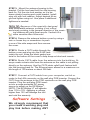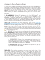
1
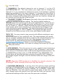
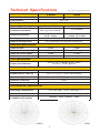
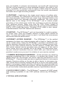
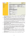
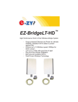
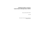
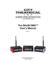
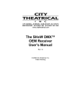
EZ-Bridge-LT ™ High Performance Point to Point Wireless Bridge System ▫ ▫ ▫ ▫ ▫ Achieve up to 15 Mbit/sec speed; 20Mbps for 5GHz version Link up to 3 miles with good line of sight Plug and Play Simple Installation Best security available (WPA) Field Proven Wireless Technology DANGER! Avoid Powerlines! You Can Be Killed! When following the instructions in this guide to install the antenna take extreme care to avoid contact with overhead power lines, lights and power circuits. Contact with power lines, lights or power circuits may be fatal. We recommend to install antenna no closer than 20 feet to any power lines. Safety: For your own protection, follow these safety rules. ▫ ▫ ▫ ▫ ▫ Perform as many functions as possible on the ground Do not attempt to install the antenna on a rainy, windy or snowy day or if there is ice or snow accumulation at the install site or if the site is wet. Make sure there are no people, pets, etc. below when you are working on a roof or ladder. Watch out for any power lines which may be overhead, underground or behind walls, keeping safely clear of them with the antenna, ladders or any tools. See appendix for FCC RF exposure guidelines Recommended Tools: Pliers, Screws and screwdriver if mounting to a wall. NOTE: You should be familiar with using tools such as these before attempting installation of the antenna. You should be comfortable with working on a ladder. Note: We highly recommend connecting the EZ-Bridge™ power supply to a surge protected outlet or an Uninterruptable Power Supply system. We also recommend using shielded and grounded CAT5 cable between the antenna and the POE Inserter. This will help prevent damage from lightning and electrical surges caused by lightning. Getting Started We strongly recommend that you setup the EZ-Bridge™ system in a single room to get acquainted with the operation of the units before installing outdoors. Connect 1 EZ-Bridge™ to your router, switch or computer and just power up the other EZ-Bridge™. Make sure the antennas are pointing away from each other for best results. After powering up each unit, you should be able to communicate with each unit. Down-load the Discovery Tool from ez-bridge.com/support/support.htm. Run the discovery tool on a connected computer. The tool should be able to find both EZ-Bridge units. 2 In the example above the numbers next to “Discovery Tool” (192.168.1.253) is the IP address for the computer that opened the Discovery Tool. To access the EZ-Bridge™, your computer IP address must be on the same subnet ie; 192.168.1.xxx. In the example above .253 replaces .xxx . If your computer is not on the same subnet as the EZ-Bridge™ units you will either need to change the IP address of your computer or the EZ-Bridge™. Before you install the units it is important to be sure that you can login to each bridge. Check the dBm: Due to the close proximity this will most likely be -30. Also check the Tx and Rx rates: If the units have established a link you should have a Tx and Rx of 54. The Tx and Rx number will increase the longer the units are connected so don’t be concerned if you have a low number as long as you have a rate above 10 to 20 on each the bridge. Qwik Install STEP 1: Choose a mounting location with good line of sight to the remote location. The supplied bracket can be mounted to a wall or to an existing pole up to 2” diameter. If only really short distances are needed, the antenna can be mounted inside a building. TECH TIP: Microwaves travel in straight lines and they lose strength quickly when going thru buildings and trees. If there are objects in the microwave path, then useable distance will be reduced. If the target unit is less than 1 mile away then you won’t have to worry too much about a couple obstructions but if over 1 mile and there are some obstructions in the microwave path, then the performance will be reduced. 2.4GHz is more forgiving than 5GHz. STEP 2: Mount the Bracket: To mount to a wall: The supplied u-bolt is not used and the bracket is screwed directly to a wall using customer supplied screws. To mount to a pole: Use the supplied U-Bolt and wing nuts. Make sure to use a lock washer at each wing nut. Tighten wing nuts evenly by hand. Use pliers if additional tightness is needed. 3 STEP 3: Mount the antenna housing to the bracket. Put the hex head bolt thru the housing back fin. Put the star lock washer so it is between plastic housing and metal bracket. Install wing nut with lock washer. Adjust desired tilt angle and tighten wing nut. Use pliers if additional tightness is needed. TECH TIP: Because of the specially designed wide beamwidth antenna, pointing is not critical and simply pointing in the general direction of the receiving antenna will yield great results. Vertical tilt is more sensitive than horizontal. STEP 4: Remove the antenna bottom cover by using a coin or house key or screwdriver to push in one of the side snaps and then remove the cover. STEP 5: Route a CAT5 cable through the bottom cover and plug into the RJ45 Jack inside the unit. Keep the black gasket material in the bottom of the cover to help keep out dust and insects. STEP 6: Route CAT5 cable from the antenna into the building. Always create a strain relief near the antenna so the cable is not pulling directly on the antenna. Use the CAT5 strain relief hook feature built into the housing back fin. The Ethernet spec allows for a maximum cable length of 100 meters or about 328 feet. STEP 7: Connect a CAT5 cable from your computer, switch or router to the LAN connector on the wall plug POE inserter. Connect the CAT5 from the antenna to the POE connector on the wall plug POE inserter. Plug the wall plug POE inserter into a surge protected AC power source to power up the EZ-Bridge™. NOTE: The EZ-Bridge LT will operate from 12V to 15V. Applying a voltage higher than 15V will damage the unit and void the warranty. Software Settings We strongly recommend that you create a working plug and play link before making ANY 4 changes to the software settings 1. There is an HTML management system built into every EZ-Bridge™ unit which is accessed thru a standard web browser. The unit can communicate thru the CAT5 Ethernet cable connection or thru the wireless connection, so you can manage remote units from a single location. NOTE: The device will usually go into a 2 minute reboot cycle When clicking on APPLY CHANGES. During this time it will be unresponsive. 2. IP ADDRESS: Default IP addresses for the EZ-Bridge™ are 192.168.1.139 and 192.168.1.239. To access the EZ-Bridge™ your computer IP address must be on the same subnet ie; 192.168.1.xxx. The EZ-Bridge ships with DHCP client enabled so if the unit has access to your network it will get its IP address automatically from your network. To find the units IP address use the Discovery Tool. TECH TIP: Download the EZ Discovery Tool from http://ezbridge.com/support/support.htm . This tool will assist you in finding the EZ-Bridge™ on the network and allow you to change the static IP address or set it as a DHCP client. Just select the unit, click on IP DETAILS, make selections, enter the user name and password and save changes directly to the device. We recommend always making changes to the remote unit first. 3. SECURITY: Security is pre-configured with system passwords, WPA2 encryption and Mac Address verification pre-set. This is so that you can setup a plug and play link and have confidence that the link is secure and that your data and network are safe. Once you feel comfortable with the system and its operation, we would recommend the following security changes : a. PASSWORD: Change the user name and password on each side of the link by going to ADMIN | Web Access and resetting the first user name and password. The default is user name = EZTEAM and password = link4me b. ENCRYPTION: Change the WPA2 encryption key by going to SECURITY SETTINGS . TECH TIP: When setting encryption you must setup both sides of the link to have identical encryption keys. You can setup the remote unit first and then the local unit last in order to be able to configure both units from one location across the wireless link. HEX Encryption keys can use the letters A to F, a to f and numbers 0 to 9. Passphrase keys can use any ASCII characters. The more random the key, the more se5 cure the code. 4. CHANNELS: The default channel is set to channel 11 on the LT2 and 149 on the LT5. The only reason you might want to change the channel is if you experience interference from local wireless systems which are operating on the same channel. To change the channel go to WIRELESS and change the channel. Both sides of the link must be on the same channel and if setting both units from one location, always set the remote unit first and the local unit last. 5. TRANSMIT POWER (Tx Power): Normally there wouldn’t be any reason to change the power setting. The factory default setting is 250mW which should be good for most applications. If you have a very short link you will actually get better performance if you turn down the Tx Power to ~100mW. This is because at close range there is too much power and it has a tendency to overload the input stage of the units and performance degrades. The best performance will be seen with signal strength of –40 to –60dBm. This signal strength can be viewed on the Status screen of the units web based control panel. TECH TIP: You may want to play around with different settings to see what works best for your particular link. The measurement you would use to compare settings would be to measure the actual thruput by timing the transfer of data across the link. One program that we have found useful for determining thruput is DISKBENCH. (http:// nodesoft.com/DiskBench/). Keep in mind that DiskBench displays speed in Bytes per second. You have to multiply the results by 8 to get Bits per second. 6. SITE SURVEY: The site survey is a very useful tool to determine what wireless devices are within range of your EZ-Bridge™ and could be a source of interference that could cause degraded performance. Go to WIRELESS and then click on SITE SURVEY then REFRESH. The list will show all wireless devices including channel #, MAC Address and relative signal strength of all the devices within the range of the EZBridge™ . NOTE: Because SSID broadcast is disabled for security reasons, the EZ-Bridge™ won’t normally show up in any site survey. 7. FACTORY DEFAULTS: If at any time the system stops working because of changes made to the settings, you can get back to the original settings by resetting to factory defaults. Go to ADMIN | Reset Settings to Defaults. You will need to reset both sides of the link in this way. Always reset the remote unit first and the local unit second. Any customized settings will be lost once this process is initiated. 6 Technical Specifications Standards Certifications Note: Subject to Change Without Notice 2.4GHz 5GHz 802.11b/g 802.11a FCC / CE Radio Specifications Operating Frequency Available Transmit Power (software selectable) 2400 to 2497MHz 4900 to 6000MHz 802.11b 100 to 250mW 802.11g 50 to 100mW 10 to 398mW -73 @ 54Mbps -84 @ 11Mbps -74dBm @ 54 Mbps -94dBm @ 6 Mbps Receive Sensitivity Security 64/128bit WEP, WPA, WPA2 Remote Configuration By IP Address; thru Wireless or Ethernet Antenna Specifications Antenna Gain Antenna Beamwidth (H /V) 14 dBi 19 dBi 35/25 deg 21/10 deg Antenna Front to Back >20dB >23dB Polarization Vertical Vertical POE Specification INPUT: 100 – 240VAC @ 50 – 60Hz OUTPUT: 15VDC @ 0.9A Power Over Ethernet Mechanical Specifications Color White Dimensions (L x W x H) 12.4” x 7.3” x 2.5” (314 x 187x 65mm) System Weight 7 lb (3 kg) Ethernet Connector RJ45 Mount Pole (up to 2” dia) or Wall Environmental Specifications Operating Temperature -31 to 140 Deg F (-35 to +60 Deg C) Humidity Wind Loading (125MPH survivability) 0 to 100% RH 100MPH / 23lbs; 125MPH / 35lbs 2.4GHz 5GHz 7 If you cannot access the web page on the unit you can do a manual reset. Remove bottom cover of unit. Power up the unit, wait 2 mins, press and hold the black reset button for 15secs, release and wait 2 mins for reboot. 8. UPGRADE FIRMWARE: For the latest firmware point your browser to http://ez-bridge.com/support/support.htm Download the latest firmware to your PC. Select UPGRADE from the menu and then browse for the new file. 9. CHANGING TO CLIENT: The EZ-Bridge™ can be changed to a client device on the WIRELESS|BASIC SETTINGS page. You might change to client if you wanted to have multiple units communicating with a single access point. If changing to client, make sure the BSSID field is changed to all zero’s or else client will lose connection with the AP after any reboot. 10. CHANGING TO ACCESS POINT: The EZ-Bridge™ can be changed to an access point device on the WIRELESS|BASIC SETTINGS page. You might want to change one unit to access point if you will have multiple clients bridging in a point to multipoint configuration. 11. WDS MESH NETWORK: You can add additional EZ-Bridge™ units or EZ-Go® Network Expansion units to link 3 or more buildings together. We suggest maximum of 6 buildings and for better performance, no more than 4. To add an EZ-Bridge™or EZ-Go® unit to the existing EZ-Bridge network, you set the operating mode to WDS and you program the remote units MAC address into the local units WDS table and the local units MAC address into the remote units WDS table. The WDS table is found under WDS SETTINGS from the main menu after setting the device to WDS. The MAC address for each unit is found on the STATUS page or can be found using the Discovery Tool. When entering MAC’s you enter just the HEX characters without the “:” (colon) Advanced Features The EZ-Bridge™ has many advanced features if more functionality is desired. To access the advanced features, click on Advanced Web at the top of the menu tree. This will activate the advanced menu options. The EZ-Bridge™ can operate as Access Point, Client, WDS, AP+WDS, Point to Point. Go to WIRELESS | BASIC SETTINGS to change wireless mode. Go to ETHERNET | IP SETTINGS to change network operation mode from Bridge (default) to Router. Since documentation for these advanced modes is too extensive to 8 cover here please retrieve the documentation online at http://ezbridge.com/support/support.htm TECH CORNER Additional Information you may find useful 1. TROUBLESHOOTING –Link Down– If a link goes down the first thing to do is run the discovery tool from both sides of the network. The discovery tool should be able to discover both units from each side of the link. If it can see the local unit but not the remote then the wireless link is down or the remote unit is down. Run the discovery tool on the remote side. If it can see the remote unit then the wireless link is down. Reset both units to factory defaults and power cycle them. If it cannot see the remote unit from the remote side, bring the power supply and POE Inserter cable from the working side and see if that fixes the problem. Also check your cables. 2. TROUBLESHOOTING—Poor Performance– If you are seeing poor performance, power cycle both units then after about 2 minutes check the signal strength on the status page of the web based control panel. If signal strength is between –80 and –90dBm the signal level is abnormally low and could be because the antennas have lost their physical alignment. Check the alignment. Antennas are more sensitive to vertical tilt than horizontal. Next, make sure there haven’t been any changes to line of site like new trees or buildings or vehicles. Line of site issues can usually be helped by moving the antenna to a new location with better line of site. If signal level is good (between –35 and –79dBm) try changing the wireless channel on both units. You should also do a site survey on both units to see what channels are already being used. Select a channel that is not already used or one that has a very low signal strength. Always change the channel on the remote unit first and local unit second. 3.RAIN, SNOW, ICE – The frequencies being used by the EZ-BridgeLT™ will not be affected by heavy rain or falling snow. You should not see any performance degradation due to inclement weather. If snow or ice collects on the front of the antenna, you may see some reduced performance assuming you are shooting a long distance ( >2miles) and the ice or snow buildup is greater than 1” thick on the surface of the antenna. For this reason, we suggest mounting under an eave of a house if feasible for your particular situation. 4.SUN AND HEAT– The EZ-Bridge™ is constructed of all UV protected materials so it will survive for many years in the most extreme of solar environments (ie; an Arizona rooftop during the summer). The unit has been tested and qualified for constant operation at over 122 deg F ambient temperature. Even though the EZ-Bridge™ is designed for long 9 term survivability in extreme environments, we would still recommend that the unit be mounted in a more protected location, like under a roof eave, if possible. Of course if line of sight is better with the antenna mounted in a non-protected environment then we would recommend the better line of sight mounting location. 5.LIGHTNING – Lightning is the single worst enemy of outdoor electronics equipment. No electronics will survive a direct strike but there are close proximity strikes that can cause huge electrical fields to be generated which can damage electronic equipment. We have taken special care in the design of the EZ-Bridge™ unit to ensure proper grounding of the electronics inside the enclosure to prevent damage from electrical storms. Make sure that the POE Power Supply is plugged into a surge protected outlet such as a surge protected power strip or UPS inside the house. Shielded CAT5 cable is also recommended between the POE Inserter and antenna. 5.PAINTING – The EZ-Bridge™ unit can be painted to match a particular house color. Only non metallic enamel or latex paints should be used. If a paint with metal content is used, it will block the microwaves and cause reduced performance. 6.INTERNET ACCESS SHARING – The EZ-Bridge™ is the perfect equipment to share your internet access with a friend or family member up to 3 miles away. Using the EZ-Bridge™ provides a seamless connection between networks and you can share the internet access available on the main network with the remote network. Please take note that certain internet service providers may not approve of this and in some cases, they may consider this to be illegal. It’s best before sharing your internet connection that you check with your internet service provider to make sure you aren’t in violation of your service contract. 7.COMMON MICROWAVE BARRIERS – Tinted windows are made by applying a metallized film to the window. If a window has tinting, it will usually block the microwaves and cause reduced performance of the EZ-Bridge™ . Concrete walls are also a significant barrier to microwave signals. Aluminum siding on houses is also a barrier to microwave signals. Wood frame houses covered with brick or stucco are pretty transparent to microwave signals and they will reduce the signal strength but the signal will still pass thru the structure. We are bringing this up to you so you can better understand possible causes of performance issues 8.VOICE OVER IP (VOIP) – The EZ-Bridge™ supports all VOIP standards making it possible to use VOIP phones across any EZ-Bridge™ link. 9.TYPICAL APPLICATIONS: 10 a. Internet access sharing – share internet access with a friend or family member b. Link your Home Office to your Main Office - you can access shared files and folders as well as print to the main office printers and use other shared network devices remotely c. Link networks in multiple buildings together – A company with multiple buildings will find the EZ-Bridge™ an inexpensive way to link their buildings together. Up to 4 buildings can be linked seamlessly using EZ-Bridge™ wireless bridges. d. Add a high speed link between your home network and a PC in your remote studio or office which is located in an outbuilding on your property. e. Create a secure link for remote video and network based security cameras. The EZ-Bridge™ works with all network based security cameras. f. Create a streaming video conference link between buildings. Because of the high 15Mb/sec and higher bandwidth available with the EZ-Bridge™ , it easily supports streaming video technologies used for remote conferencing, like church meetings, business meetings, etc. Status Screen Tour A. Switch to Advanced WEB -This control switches the menu system to an advanced menu system with all options available. For advanced users only. B. Firmware Version - This shows the firmware version loaded on the unit. Visit EZ-Bridge.com/support/support.htm for firmware updates C. System Name, Location and Contact – These are user fields. You can assign any useful information in these fields. This can be useful for identifying where the unit is located like “Mikes House” or “Barn”. D. Mode -This shows the current operating mode of the unit. E. Band - Identifies what wireless frequency and protocol the unit is set for. F. SSID - When the unit is set as a client this shows the SSID of the associated Access Point G. Channel Number - Shows the wireless channel the unit is set to. H. Encryption -Displays the current type of encryption being used. I. BSSID -This field shows the MAC Address of the other unit. J. State - Shows the present state of the unit like scanning or connected. K. dBm –This is the signal strength of the signal being received from the other unit. A great signal strength is between –40 and –60dBm. If around –30 then signal is too strong and power level should be reduced. The unit stops working at –90dBm so you don’t want to operate close to –90dBm or else the connection won’t be reliable. L. Tx Rate - This is the transmit rate of this unit in Mbps. A perfect rate is 54. Normally on a great connection the Tx rate will wander 11 M. N. O. P. Q. R. between 30 and 54. If Tx rate is 1 there is a major problem, usually bad interference on the selected channel. If the Tx rate is zero then there is no connection. Rx Rate - This is the receive rate of this unit. Same analysis as Tx rate. If either rate is too low and signal level is OK, need to reset to factory defaults, power cycle and then change channels. Problems can also be associated with multipath where you have a reflection that cancels out received signals. This is common on a unit that is mounted too close to a metal wall or a metal roof. The only option is to move the unit away from the wall or the roof. Power Settings –This shows the current power settings of the unit. The only time you would need to be concerned about power is if the signal level is too high. Attain IP Protocol -This displays if the unit is set to fixed IP or DHCP client. If set to DHCP client the unit will try to get it’s IP address from the upstream router. It will only try to get it’s IP address upon power up or upon making any changes to the unit configuration. If it doesn’t get it’s IP address it will revert to the IP address that is programmed into the unit. IP Address and Subnet Mask - Displays the current IP address and subnet mask. Default Gateway –This setting is not used in point to point bridge mode. You need to set a default gateway if you use the unit as a DHCP server, otherwise you don’t need to worry about this setting. All zeros is fine. DHCP Server –Shows the status of the on-board DHCP server. 12 Since there should be only one DHCP server on any network node, this is by default disabled. S. MAC Address –This is the MAC address of this unit T. Port Status –Shows the status of the Ethernet port (the wired port) and at what speed it is connected to your computer, switch or router or.. NOTES Appendix: Federal Communication Commission Interference Statement This equipment has been tested and found to comply with the limits for a Class B digital device, pursuant to Part 15 of the FCC Rules. These limits are designed to provide reasonable protection against harmful interference in a residential installation. This equipment generates, uses and can radiate radio frequency energy and, if not installed and used in accordance with the instructions, may cause harmful interference to radio communications. However, there is no guarantee that interference will not occur in a particular installation. If this equipment does cause harmful interference to radio or television reception, which can be determined by turning the equipment off and on, the user is encouraged to try to correct the interference by one of the following measures: Reorient or relocate the receiving antenna. Increase the separation between the equipment and receiver. Connect the equipment into an outlet on a circuit different from that to which the receiver is connected. Consult the dealer or an experienced radio/TV technician for 13 help. FCC Caution: Any changes or modifications not expressly approved by the party responsible for compliance could void the user's authority to operate this equipment. This device complies with Part 15 of the FCC Rules. Operation is subject to the following two conditions: (1) This device may not cause harmful interference, and (2) this device must accept any interference received, including interference that may cause undesired operation. IMPORTANT NOTE: FCC Radiation Exposure Statement: This equipment complies with FCC radiation exposure limits set forth for an uncontrolled environment. This equipment should be installed and operated with minimum distance 20cm between the radiator & your body. The antenna(s) used for this transmitter must not be co-located or operating in conjunction with any other antenna or transmitter. Limited Warranty All Tycon Systems products are supplied with a limited 12 month warranty which covers material and workmanship defects. This warranty does not cover the following: ▫ Parts requiring replacement due to improper installation, misuse, poor site conditions, faulty power, etc. ▫ Lightning damage. ▫ Physical damage to the external & internal parts. ▫ Products that have been opened, altered, or defaced. ▫ Water damage for units that were not sealed or mounted according to user manual. ▫ Units that were not properly grounded. ▫ Usage other than in accordance with instructions and the normal intended use. Do not return any products until you receive a Return Material Authorization (RMA) number. Products received without a valid RMA number will be rejected and returned to sender. Warranty Repairs All returns must have a valid RMA number written clearly on the outside of the box. Without an RMA number the shipment will be refused. For customers located in United States and Canada, customer pays all shipping charges incurred to ship the product to Tycon Systems. Tycon Systems pays shipping charges to return the product to the original purchaser. For all other countries, the original purchaser shall pay all shipping, broker fees, duties and taxes incurred in shipping products to and 14 from Tycon Systems. Provided the goods have not been modified or repair attempted by someone other than Tycon Systems, at the option of Tycon Systems, products may be returned either as repaired or replaced. If it is determined that there is no fault found (NFF) on a unit within warranty, the customer will be charged $75 USD for testing time. For products out of warranty, the standard NFF charge is $200. This charge will be at the discretion of Tycon Systems. The RMA number is valid for 14 days from date of issue. The product must be received by the repair depot within these 14-days or the shipment may be refused. Shipping and Damage Claims All shipping damage claims are the purchaser's responsibility. Inspect each shipment upon delivery and IMMEDIATELY report all damage, to the carrier. There may be time limits and inspections may be required. Phone: 801-432-0098 [email protected] 15 8000005 Rev 6 EZ-Bridge-LT Qwik Install Guide 16