1
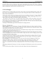
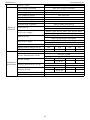
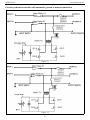
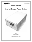
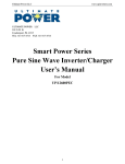
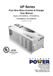
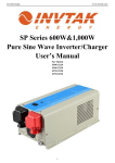
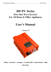
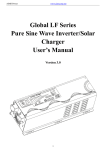
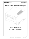
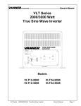
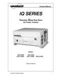
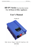
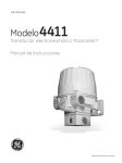
AIMS Power
www.aimscorp.net
Global LF Series
Pure Sine Wave Inverter/
Charger User’s Manual
1
AIMS Power
www.aimscorp.net
Table of Contents
1. Important Safety Information................................................................................................................................................... 3
1.1 General Safety Precautions.....................................................................................................................................................3
1.2 Precautions When Working with Batteries.............................................................................................................................3
2 Introduction................................................................................................................................................................................4
2.1 General Information............................................................................................................................................................... 4
2.2 Application..............................................................................................................................................................................5
2.3 Features...................................................................................................................................................................................5
2.4 Mechanical Drawing...............................................................................................................................................................6
2.5 Electrical Performance........................................................................................................................................................... 8
2.5.1 Invert............................................................................................................................................................................8
2.5.2 AC Charger.................................................................................................................................................................. 9
2.5.3 Transfer...................................................................................................................................................................... 11
2.5.4 Power Saver...............................................................................................................................................................12
2.5.5 Protections................................................................................................................................................................. 13
2.5.6 Remote Control......................................................................................................................................................... 14
2.5.7 LED Indicator............................................................................................................................................................ 15
2.5.8 Audible Alarm............................................................................................................................................................15
2.5.9 FAN Operation.......................................................................................................................................................... 16
2.5.10 DIP Switches........................................................................................................................................................... 16
2.5.11 Auto Generator Start................................................................................................................................................18
2.5.12 Battery Temperature Sensing.................................................................................................................................. 18
2.5.13 Other Features......................................................................................................................................................... 19
3 Installation............................................................................................................................................................................... 19
3.1 Unpacking and Inspection.................................................................................................................................................... 19
3.2 Installation Location, Tools & Materials..............................................................................................................................19
3.3 DC Wiring.............................................................................................................................................................................20
3.4 AC Wiring.............................................................................................................................................................................22
3.5 Grounding............................................................................................................................................................................. 23
3.6 Mounting the Inverter...........................................................................................................................................................24
4 Troubleshooting Guide............................................................................................................................................................ 26
5 Limited Warranty.....................................................................................................................................................................28
Appendix 1 - PICOGLF Series Spec Sheet................................................................................................................................29
Appendix 2 - Circuit Schematics................................................................................................................................................31
Appendix 3 - Installation Diagram............................................................................................................................................. 33
Appendix 4 - Inverter Efficiency................................................................................................................................................34
Please record the unit’s model and serial number in case you need to provide this information in the
future. It is much easier to record this information now than try to gather it after the unit has been
installed.
Model Number:
Serial Number:
2
AIMS Power
www.aimscorp.net
1. Important Safety Information
Save This Manual! Read this manual before installation, it contains important safety, installation
and operating instructions. Keep it in a safe place for future reference.
All wiring must follow the National Electric Code, Provincial or other codes in effect at the time
of installation, regardless of suggestions in this manual. All wires should be copper conductors.
1.1 General Safety Precautions
1.1.1 Do not expose the Inverter to rain, snow, spray, bilge or dust. To reduce risk of hazard, do not cover or
obstruct the ventilation openings. Do not install the Inverter in a zero-clearance compartment. Overheating
may result. Allow at least 30CM of clearance around the inverter for air flow. Make sure that the air can
circulate freely around the unit. A minimum air flow of 145CFM is required.
1.1.2 To avoid risk of fire and electronic shock, make sure that existing wiring is in good electrical condition
and that the wire is not undersized. Do not operate the Inverter with damaged or substandard wiring.
1.1.3 This equipment contains components which may produce arcs and/or sparks. To prevent fire and/or
explosion do not install in compartments containing batteries or flammable materials or in a location which
require ignition protected equipment. This includes any space containing gasoline-powered machinery, fuel
tanks, or joints, fittings, or other connection between components of the fuel system.
See Warranty for instructions on obtaining service.
1.1.4 Do not disassemble the Inverter/Charger. It contains no user-serviceable parts. Attempting to service
the Inverter/Charger yourself may result in electrical shock or fire. Internal capacitors remain charged after
all power is disconnected.
1.1.5 To reduce the risk of electrical shock, disconnect both AC and DC power from the Inverter/Charger
before attempting any maintenance or cleaning. Turning off controls will not reduce this risk
CAUTION: Equipment damage
The output side of the inverter’s AC wiring should at no time be connected to public power or a generator.
This condition is far worse than a short circuit. If the unit survives this condition, it will shut down until
corrections are made.
Installation should ensure that the inverter’s AC output is, at no time, connected to its AC input.
WARNING: LIMITATIONS OF USE
SPECIFICALLY, PLEASE NOTE THAT THE INVERTER/CHARGER SHOULD NOT BE USED IN
CONNECTION WITH LIFE SUPPORT SYSTEMS OR OTHER MEDICAL EQUIPMENT OR DEVICES.
WE MAKE NO WARRANTY OR REPRESENTATION IN CONNECTION WITH THEIR PRODUCTS
FOR SUCH USES. USING THE INVERTER/CHARGER WITH THIS PARTICULAR EQUIPMENT IS
AT YOUR OWN RISK.
1.2 Precautions When Working with Batteries
1.2.1 If battery acid contacts skin or clothing, wash immediately with soap and water. If acid enters eye,
immediately flood eye with running cold water and get medical attention immediately.
1.2.2 Never smoke or allow a spark or flame in the vicinity of a battery or engine.
1.2.3 Do not drop a metal tool on the battery. The resulting spark or short-circuit on the battery may cause
an explosion.
1.2.4 Remove personal metal items such as rings, bracelets, necklaces, and watches when working with a
lead-acid battery. A lead-acid battery produces a short-circuit current high enough to weld a ring or the like
to metal, causing a severe burn.
1.2.5 To reduce the risk of injury, charge only deep-cycle lead acid, lead antimony, lead calcium gel cell,
3
AIMS Power
www.aimscorp.net
absorbed mat, or NiCad/NiFe type rechargeable batteries. Other types of batteries may burst, causing
personal injury and damage.
2 Introduction
2.1 General Information
Global LF Series Pure Sine Wave Inverter/Charger is a combination of an inverter, battery charger and AC
auto-transfer switch into one complete system with a peak DC to AC conversion efficiency of 92%.
It is packed with unique features and it is one of the most advanced inverter/chargers in the market today.
It features power factor corrected, sophisticated multi-stage charging and pure sine wave output with
unprecedentedly high surge capability to meet demanding power needs of inductive loads without
endangering the equipment.
The powerful battery charger of this Series Inverter/Charger goes as high as 100Amps (varying on different
models), and with power factor corrected, it uses 20-30% less energy from AC input than a standard charger,
avoiding nuisance breaker trips or generator overloads.
In response to the increasing demand of more advanced battery charging, the latest models of this line is
equipped with Battery Temperature Sensing for increased charging precision.
The overload capacity is 300% of continuous output for up to 20 seconds to reliably support tools and
equipment longer.
The transformers have been consistently improved for years to achieve the best balance of conversion
efficiency, idle consumption and minimum THD.
The idle consumption of the line is ultra low, roughly 1.5% of its rated power.
These special features make this line compete very well with its high frequency counterparts.
The models are available in 120Vac (single phase).
The AC/Battery priority switch and auto generator start functionality make it ideally suitable to work in
either backup power or renewable energy applications.
In AC priority mode, when AC power cuts off(or falls out of acceptable range), the transfer relay is
de-energized and the load is automatically transferred to the Inverter output. Once the qualified AC power is
restored, the relay is energized and the load is automatically reconnected to AC utility.
When customized to Battery Priority Mode via a DIP switch, the inverter will extract maximum power from
external power sources in renewable energy systems and a minimal cycle of battery will be required. With
the availability of auto generator start, an electrical generator can be integrated into the system as back up
and started when the battery voltage goes low.
With audible buzzer and a remote LCD display, the inverter gives the users comprehensive information of
the operation status, making it easier for maintenance and troubleshooting.
Thus the Global LF Series Pure Sine Wave Inverter/Charger is suitable for a myriad of applications
including renewable energy systems, utility, truck, RV and emergency vehicles etc.
To get the most out of the power inverter, it must be installed, used and maintained properly. Please read the
instructions in this manual before installing and operating.
4
AIMS Power
www.aimscorp.net
2.2 Application
Power tools–circular saws, drills, grinders, sanders, buffers, weed and hedge trimmers, air compressors.
Office equipment – computers, printers, monitors, facsimile machines, scanners.
Household items – vacuum cleaners, fans, fluorescent and incandescent lights, shavers, sewing machines.
Kitchen appliances – coffee makers, blenders, ice markers, toasters.
Industrial equipment – metal halide lamp, high – pressure sodium lamp.
Home entertainment electronics – television, VCRs, video games, stereos, musical instruments, satellite
equipment.
2.3 Features
High overload ability up to 300% of rated power (20 sec)
Low quiescent current, low power “Power Saving Mode” to conserve energy
Automatic Generator Start
Battery Temperature Sensing for increased charging precision
4-step intelligent battery charger, PFC (Power Factor Correction) for charger
8 pre-set battery type selector switch plus de-sulphation for totally flat batteries
Powerful charge rate of up to 100Amps, selectable from 0%-100%
10 ms typical transfer time between battery and AC, guarantees power continuity
Smart LCD remote control panel
Automatic ground & neutral bonding with manual disability (for 120Vac models)
15s delay before transfer when AC resumes, extra protection for loads when used with generator
Allows start up and through power with depleted batteries
Multiple controlled cooling fans
Extensive protections against various harsh situations
13VDC battery recovery point, dedicated for renewable energy systems
5
AIMS Power
www.aimscorp.net
2.4 Mechanical Drawing
PICOGLF 1-3KW Models DC Side (Figure 1)
Figure 1
PICOGLF 1-3KW Models AC Side (Figure 2)
Figure 2
6
AIMS Power
www.aimscorp.net
PICOGLF 1-3KW Models TOP Side (Figure 3)
Figure 3
7
AIMS Power
www.aimscorp.net
2.5 Electrical Performance
2.5.1 Invert
Topology
The Global LF inverter/charger is built according to the following topology.
Invert: Full Bridge Topology.
Charge: Isolated Boost Topology.
It works bi-directionally: in one direction it converts DC power from the battery to AC power (Inverter
Mode) and in the other direction it converts external AC power to DC power to charge the batteries (AC
Mode). The same power components are used in both directions, resulting in high-energy transfer efficiency
with fewer components.
Please note that the inverter/charger can only work in one direction at one time (i.e. it can not work as an
inverter and as a charger at the same time).
When operating in invert mode, the direct current (DC) that enters the inverter from the batteries is filtered
by a large input capacitor and switched “On” and “Off” by the Metal Oxide Silicon Field Effect Transistors
(MOSFET) at a rate of 50 Hz or 60Hz, in this step the DC is converted to low voltage synthesized sine wave
AC using an H-bridge configuration and high frequency PWM (Pulse Width Modulation) technique. It is
then directed into the transformer which steps the low AC voltage up to 230 or 120 volts.
The unit has a 16bit, 4.9MHZ microprocessor to control the output voltage and frequency as the DC input
voltage and/or output load varies.
Because of high efficiency MOSFETs and the heavy transformers, it outputs PURE SINE WAVE AC with
an average THD of 10% (min 3%, max 20% under full linear loads) depending on load connected and
battery voltage.
The peak DC to AC conversion efficiency of the Global LF series is 92%.
Don’t parallel the AC output of the inverters to increase power capacity as they have no
stacking functionality.
Overload Capacity
The Global LF series inverters have high overload capacities, making it ideal to handle demanding loads.
1 For 110%<Load<125%(±10%), no audible alarm for 14 minutes, beeps 0.5s every 1s in the 15th minute,
and Fault(Turn off) after the 15th minute.
2 For 125%<Load<150%(±10%), beeps 0.5s every 1s and Fault(Turn off) after 1 minute.
3 For 300%≧Load>150%(±10%), beeps 0.5s every 1s and Fault(Turn off) after 20s.
Soft Start in Inverter Mode
The inverter is engineered with “Soft Start” feature.
When the inverter is turned on, the output voltage gradually ramps up from 0VAC to rated voltage in about
1.2 sec. This effectively reduces otherwise very high starting inrush current drawn by AC loads such as
Switched Mode Power Supplies and inductive loads. This will result in lower motor inrush current, which
means less impact on the loads and inverter.
Caution:
After the inverter is switched on, it takes a finite time for it to self diagnose and get ready to deliver full
power. Hence, always switch on the load(s) after a few seconds of switching on the inverter. Avoid
8
AIMS Power
www.aimscorp.net
switching on the inverter with the load already switched on. This may prematurely trigger the overload
protection. When a load is switched on, it may require initial higher power surge to start. Hence, if multiple
loads are being powered, they should be switched on one by one so that the inverter is not overloaded by the
higher starting surge if all the loads are switched on at once.
2.5.2 AC Charger
Global LF Series is equipped with an active PFC (Power Factor Corrected) multistage battery charger. The
PFC feature is used to control the amount of power used to charge the batteries in order to obtain a power
factor as close as possible to 1.
Unlike other inverters whose max charging current decreases according to the input AC voltage, Global LF
series charger is able to output max current as long as the input AC voltage is in the range of 95-127VAC,
and AC freq is in the range of 48-54Hz(58-64Hz for 60Hz model).
The Global LF series inverter has a very rapid charge current available, and the max charge current can be
adjusted from 15%-100% via a liner switch to the right of the battery type selector. This will be helpful if
you are using our powerful charger on a small capacity battery bank. The liner switch can effectively reduce
the max charging current to 15% of its peak.
Choosing “0” in the battery type selector will disable the charging function.
There are 3 charging stages:
Bulk Charging: This is the initial stage of charging. While Bulk Charging, the charger supplies the battery
with controlled constant current. The charger will remain in Bulk charge until the Absorption charge voltage
(determined by the Battery Type selection) is achieved.
A software timer will measure the time from A/C start until the battery charger reaches 0.3V below the boost
voltage, then take this time asT0 and T0×10 = T1.
Absorb Charging: This is the second charging stage and begins after the absorb voltage has been reached.
Absorb Charging provides the batteries with a constant voltage and reduces the DC charging current in order
to maintain the absorb voltage setting.
In this period, the inverter will start a T1 timer; the charger will keep the boost voltage in Boost CV mode
until the T1 timer has run out. Then drop the voltage down to the float voltage. The timer has a minimum
time of 1 hour and a maximum time of 12 hours.
Float Charging: The third charging stage occurs at the end of the Absorb Charging time. While Float
charging, the charge voltage is reduced to the float charge voltage (determined by the Battery Type
selection*). In this stage, the batteries are kept fully charged and ready if needed by the inverter.
If the A/C is reconnected or the battery voltage drops below 12Vdc/24Vdc, the charger will restart the above
cycle.
If the charge maintains the float state for 10 days, the charger will deliberately reset the cycle to protect the
battery.
Curves in below picture (Figure 5) show the current and voltage in the battery charging process.
9
AIMS Power
www.aimscorp.net
Figure 5
De-sulphation
The de-sulphation cycle, switch position 8, is
marked in red because this is a very
dangerous setting if you do not know what
you are doing. Before attempting to use this
cycle you must clearly understand what it
does and when and how you would use it.
What causes sulphation? This can occur with
infrequent use of the batteries, or if the
batteries have been discharged so low that
they will not accept a charge. This cycle is a
very high voltage charge cycle designed to try
to break down the sulphated crust that is
preventing the plates from taking a charge and
thus allow the plates to clean up and accept a
charge once again.
Battery Type Selector Settings
Switch
Description
Position
Boost / Vdc Float / Vdc
0
Charger Off
1
Gel USA
14.0
13.7
2
AGM 1
14.1
13.4
3
AGM 2
14.6
13.7
4
Sealed lead acid 14.4
13.6
5
Gel EURO
14.4
13.8
6
Open lead acid
14.8
13.3
7
Calcium
15.1
13.6
8
De-sulphation
15.5 (4 Hours then Off)
9
Not used or customized*
Above figures based on 12Vdc models, *2 for 24Vdc,
*4 for 48Vdc.
*For some customized models, position 9 is
programmed with a customized algorithm. Please
refer to the product label or the manufacturer for
more information.
Charging depleted batteries
The Global LF series inverter allows start up
and through power with depleted batteries.
For 12VDC models: after the battery voltage goes below 10V and the power switch is kept in the "ON"
position and the inverter stays connected to the battery and the battery voltage doesn’t drop below 2V, the
inverter will be able to charge the battery once qualified AC inputs are present.
10
AIMS Power
www.aimscorp.net
Before the battery voltage goes below 9VDC, the charging can be activated when the switch is turned to
“Off”, then to “ON”.
When the voltage goes below 9VDC, and you accidently turn the switch to OFF or disconnect the inverter
from the battery, the inverter will not be able to charge the battery once again, because the CPU loses
memory during this process.
Charging current for each model
Model
PICOGLF10W12V120V
PICOGLF15W12V120V
PICOGLF20W12V120V
PICOGLF30W12V120V
Current
35A
50A
70A
100A
The charging capacity will go to peak charge rate in about 3 seconds. This may cause a generator to drop
frequency, making the inverter transfer to battery mode.
It is suggested to gradually put the charging load on the generator by switching the charging switch from
min to max. Together with the 15s switch delay our inverter gives the generator enough time to spin up.
This will depend on the size of the generator and rate of charge.
As a general Rule, the Bulk Charging Current should be limited to 30% of the capacity of the battery bank.
Higher charging current may be used if permitted by the battery manufacturer.
Caution:
Please use a small jeweler’s style flat-head screwdriver to turn the charge current
control switch gently to avoid breakage due to over-turning.
To guarantee the best performance of AC charger when the AC input is from a
generator, the standby generator should be of at least 150% higher capacity than the
inverter.
Warning! Operation with an under-rated generator or generator with unqualified
wave form may cause premature failure which is not under warranty.
2.5.3 Transfer
Swift Power Transfer
While in the Standby Mode, the AC input of the inverter is continually monitored. Whenever AC power falls
below the low AC voltage trip voltage (90VAC default setting for 120VAC), the inverter automatically
transfers back to the Invert Mode with minimum power interruption to your appliances - as long as the
inverter is turned on. The transfer from Standby mode to Inverter mode occurs in approximately 10
milliseconds. And it is even shorter from Inverter mode to Standby mode.
This transfer time is usually fast enough to keep your equipment (including computers) powered up, thus our
inverter can be used as a line interactive UPS.
Synchronized Power Transfer
When a load is transferred from inverter AC output to another backup AC source of power through a transfer
switch, there will be a finite interruption of power to the load for the transfer to take place.
A mismatch of phase and frequency of the inverter AC output and the backup AC source in transfer is likely
to damage the backup AC source / a reactive load.
With sophisticated circuitry design, our inverter will first lock on the frequency and phase of the input shore
11
AIMS Power
www.aimscorp.net
power/generator power and make a smooth and safe transfer at the zero voltage point to minimize the impact
on the power modules.
Transfer Delay
There is a 15-second delay from the time the inverter senses that continuously qualified AC is present at the
input terminals to when the transfer is made. This delay is built in to provide sufficient time for a generator
to spin-up to a stable voltage and frequency and avoid relay chattering. The inverter will not transfer to
generator until it has locked onto the generator’s output. This delay is also designed to avoid frequent
switching when input utility is unstable.
2.5.4 Power Saver
There are two different working statuses for our Global LF inverter:
“Power On” and “Power Off”.
When the power switch on power switch panel (Figure 7) is in “Unit
Off” position, the inverter is powered off.
When the power switch is turned to either of “Power Saver Auto” or
Figure 7
“Power Saver Off”, the inverter is powered on.
Power saver function is designed to conserve battery power when AC power is not or rarely required by the
loads.
In this mode, the inverter pulses the AC output looking for an AC load (i.e., electrical appliance). Whenever
an AC load (greater than 50 watts) is turned on, the inverter recognizes the need for power and automatically
starts inverting and output goes to full voltage. When there is no load (or less than 50 watts) detected, the
inverter automatically goes back into search mode to minimize energy consumption from the battery bank.
In “Power saver on” mode, the inverter will draw power mainly in sensing moments, thus the idle
consumption is significantly reduced.
The inverter is factory defaulted to detect load for 250ms every 3 seconds. This power sensing can be
customized to “Unit off charging” via the SW3 on DIP switch.
Power saver on
Power saver off
Power saver on (Load detected)
Figure 8
Figure 9
Figure 10
Note: The minimum power of a load to take inverter out of sleep mode (Power Saver On) is 50 Watts. For
split phase models, the power threshold of sleep mode is 50W between Hot1 and Neutral and 200W between
Hot 1 and Hot 2. There is no load detection between Hot2 and Neutral.
The Global LF Series is designed with extraordinarily low idle power consumption which is only a mere
0.8-1.8% of its rated power.
12
AIMS Power
www.aimscorp.net
Global LF Series Idle Power Consumption (in Watts)
Model NO
Power Saver Off
Power Saver On (3Secs)
PICOGLF10W12V120V
PICOGLF15W12V120V
12.5
13.5
7.5
8
PICOGLF20W12V120V
28
12.7
PICOGLF30W12V120V
55
21.7
When in the search sense mode, the green power LED will blink and the inverter will make a ticking sound.
At full output voltage, the green power LED will light steadily and the inverter will make a steady humming
sound. When the inverter is used as an “uninterruptible” power supply the search sense mode or “Power
Saver On” function should be defeated.
Exceptions
Some devices when scanned by the load sensor cannot be detected. Small fluorescent lights are the most
common example. (Try altering the plug polarity by turning the plug over.) Some computers and
sophisticated electronics have power supplies that do not present a load until line voltage is available. When
this occurs, each unit waits for the other to begin. To drive these loads either a small companion load must
be used to bring the inverter out of its search mode, or the inverter may be programmed to remain at full
output voltage (Power On mode).
2.5.5 Protections
The Global LF series inverter is equipped with extensive protections against various harsh situations/faults.
These protections include:
AC Input over voltage protection/AC Input low voltage protection
Low battery alarm/High battery alarm
Over temperature protection/Over load protection
Short Circuit protection (1s after fault)
Back feeding protection
When Over temperature /Over load occur, after the fault is cleared, the master switch has to be reset to
restart the inverter.
The Low battery voltage trip point can be customized from a defaulted value of 10VDC to 10.5VDC thru
SW1 on the DIP switch.
The inverter will go to Over temp protection when the heat sink temp is over 105ºC(221℉), and go to Fault
(shutdown Output) after 30 seconds. The switch has to be reset to activate the inverter.
The Global LF series Inverter has back feeding protection which avoids presenting an AC voltage on the AC
input terminal in Invert mode.
After the reason for the fault is cleared, the inverter has to be reset to start working.
13
AIMS Power
www.aimscorp.net
2.5.6 Remote Control
Apart from the switch panel on the front (or top) side of the inverter, an extra LCD remote switch panel
(Figure 11, sold separately Part #: REMOTELF) connected to the remote port at the DC side of the inverter
through a standard Ethernet cable can also control the operation of the inverter.
If an extra switch panel is connected to the inverter via “remote control port”, together with the panel on the
inverter case, the two panels will be connected and operated in parallel.
Whichever first switches from “Off” to “Power saver off” or “Power saver on”, it will power the inverter
on.
If the commands from the two panels conflict, the inverter will operate according to the following priority:
Power saver on> Power saver off> Power off
Only when both panels are turned to the “Unit Off” position, will the inverter be powered off.
The Max length of the LCD remote
control data cable is 60 feet (18 meters).
The LCD remote control panel will
display the operation status of the inverter,
including:
Input AC Voltage
Output AC Voltage
Battery Voltage
Output Frequency
Output Load
Work Mode
Alarm
Fault
Battery Capacity
A push button on the left of the panel can
be used to turn off the LCD screen and
save 0.1A current draw on the battery.
Figure 11
WARNING
Never cut the Ethernet cable when the cable is attached to inverter and battery is connected to the inverter.
Even if the inverter is turned off, it will damage the remote PCB inside if the cable is short circuited during
cutting.
14
AIMS Power
www.aimscorp.net
2.5.7 LED Indicator
The operation status of the inverter is shown by the LED’s and the explanation on the LED sticker (Figure
12).
Figure 12
2.5.8 Audible Alarm
The inverter also gives audible alarms when the following situations occur.
Battery Voltage Low
Inverter green LED lit, and the buzzer beeps 0.5s every 5s.
Inverter green LED lit, and the buzzer beeps 0.5s every 1s and Fault after
Battery Voltage High
60s.
(1)110%<load<125%(±10%), No audible alarm in 14 minutes,
Beeps 0.5s every 1s in 15th minute and Fault after 15 minutes;
Invert Mode Over-Load
(2)125% <load<150%(±10%), Beeps 0.5s every 1s and Fault after 60s;
(3)Load>150%(±10%), Beeps 0.5s every 1s and Fault after 20s;
Heat sink temp. ≥105ºC(221℉), Over temp red LED Lighting, beeps 0.5s
Over Temperature
every 1s;
15
AIMS Power
www.aimscorp.net
2.5.9 FAN Operation
For 1-3KW models, there is one multiple controlled DC fan which starts to work according to the below
logic.
The Operation of the DC fan at the DC terminal side is controlled by the following logic:
Condition
Enter Condition
T ≤ 60℃(140℉)
HEAT SINK
65℃(149℉)≤ T < 85 ℃(185℉)
TEMPERATURE
T > 85℃(185℉)
I ≤ 15%
CHARGER
20%< I ≤ 50%Max
CURRENT
I > 50%Max
Load < 30%
LOAD Percentage
30% ≤ Load < 50%
(INV MODE)
Load ≥ 50%
Leave condition
T > 65℃(149℉)
T ≤ 60℃(140℉) or T ≥ 85℃(185℉)
T ≤ 80℃(176℉)
I ≥ 20%
I≤ 15% or I > 50%Max
I ≤ 40%Max
Load ≥ 30%
Load ≤ 20% or Load ≥ 50%
Load ≤ 40%
Speed
OFF
50%
100%
OFF
50%
100%
OFF
50%
100%
Allow at least 30CM of clearance around the inverter for air flow. Make sure that the air can circulate freely
around the unit.
Fan noise level <60db at a distance of 1m
2.5.10 DIP Switches
On the DC end of inverter, there are five DIP switches which enable users to customize the performance of
the device.
Switch #
SW1(Utility Priority)
SW1(Battery Priority)
SW2
SW3
SW4
SW5
Switch Function
Low Battery Trip Point
AC Input Range
Power Save Override ON/OFF
Frequency Switch
Battery/AC Priority
Position: 0
10.0VDC
10.5VDC
100-135VAC
Inverter Off
50Hz
AC Priority
Position: 1
10.5VDC
11.5VDC
90-135VAC(40Hz+)
Power Saver On( 3 sec)
60Hz
Battery Priority
Low Battery Trip Point (SW1):
Deep discharge of the lead acid battery leads to high losses in capacity and early aging. In different
applications a different low voltage disconnection level is preferred. For example, for solar applications,
user may intend to have less DOD to prolong the battery life cycle. While for mobile applications users may
intend to have more DOD to reduce battery capacity and on board weight.
For 12VDC models, when the inverter is in AC priority mode (SW5 at “0”), Low Battery Trip Point is
selectable at 10.0/10.5VDC. It can be customized to 10.5/11.5VDC via SW5. This is to prevent batteries
from over-discharging while there is only a small load applied on the inverter.
AC Input Range (SW2):
There are different acceptable AC input ranges for different kinds of loads.
For some relatively sensitive electronic devices, a narrow input range of 100-135V is required to protect
them.
16
AIMS Power
www.aimscorp.net
While for some resistive loads which work in a wide voltage range, the input AC range can be customized to
90-135V, this helps to power loads with the most AC input power without frequent switches to the battery
bank.
In order to make the inverter accept dirty power from a generator, when the SW2 is switched to position “1”,
the inverter will bypass an AC input with a wider voltage and frequency (40Hz plus for 50Hz/60Hz).
Accordingly, the AC charger will also work in a wider voltage and freq range (43Hz plus for 50Hz/60Hz).
This will avoid frequent switches between battery and generator. But some sensitive loads will suffer from
the low quality power.
The pros and cons should be clearly realized.
Power Save Override ON/OFF (SW3):
Under the Battery Priority Mode (SW5 in position “1”), the inverter can be switched between two modes:
Power Saver Mode (SW3 in position “1”) and Unit Off Charging Mode (SW3 in position “0”). The power
Switch should be in “Power saver on” position all the time for using these functions.
In Power Saver Mode, the inverter is initially in standby mode and sends a pulse to detect the presence of a
load every 3 seconds. Each pulse lasts for 250ms. The inverter will remain in standby mode until a load has
been detected. Then it will wake up from standby mode and start to invert electricity from the battery bank
to supply the load. As this function is under Battery Priority, the inverter will always prefer to invert
electricity from battery first even there is a qualified AC input present. Only when the battery voltage is
lower than the low voltage alarm point, will the inverter switch to AC input power to charge the battery and
supply the load at the same time.
This Power Saver Mode can be changed to Unit Off Charging mode via SW3 by switching it to “0” position
(SW5 still in “1”).
In Unit Off Charging mode, the inverter will stay in standby mode without sensing loads. It won’t output
any power even if a load is turned on or a qualified AC input is present. The inverter will not perform any
function and only stay idle in this mode, unless the battery voltage is low. Then it will start charging the
battery. This feature is ideally suitable for applications where energy conservation is required. Charging will
only be activated when required.
Frequency Switch (SW4):
The output frequency of the inverter can be set at either 50Hz or 60Hz by SW4.
AC/Battery Priority (SW5):
Our inverter is designed with AC priority by default. This means, when AC input is present, the battery will
be charged first, and the inverter will transfer the input AC to power the load. Only when the AC input is
stable for a continuous period of 15 days will the inverter start a battery inverting cycle to protect the
battery. After 1 normal charging cycle ac through put will be restored.
The AC Priority and Battery Priority switch is SW5. When you choose battery priority, the inverter will
invert from battery despite the AC input. Only when the battery voltage reaches the low voltage alarm
point(10.5Vdc for 12Vdc, 21Vdc for 24Vdc, 42Vdc for 48Vdc), will the inverter transfer to AC input,
charge battery, and switch back to battery when the battery is fully charged. This function is mainly for
wind/solar systems using utility power as back up.
Note: In battery priority mode, when qualified AC inputs for the first time and the battery voltage is
below 12.5Vdc (12.5Vdc for 12Vdc, 25Vdc for 24Vdc, 51Vdc for 48Vdc), the inverter will go into
battery priority mode only after a cycle of bulk charging and absorb charging is finished. The inverter
will not go into float charging mode.
17
AIMS Power
www.aimscorp.net
2.5.11 Auto Generator Start
The inverter can start up generator when battery voltage goes low.
When the inverter goes to low battery alarm, it can send a signal to start a generator and turn the generator
off after battery charging is finished.
The auto gen start feature will only work with generators which have automatic starting capability. The generator
must have start and stop controls [i.e., an electric starter and electric choke (for gasoline units)], and the safety
sensors to be able to start and stop automatically.
There is an open/close relay that will short circuit the positive and negative cables from a generator start control.
The input DC voltage can vary, but the max current the relay can carry is 16Amp.
The Auto Generator Start terminal pins are not polarized.
In addition, these two pins can also be used as dry contacts to send out “Low Battery Voltage” signal to an
external alarm device.
2.5.12 Battery Temperature Sensing
Applying the proper charge voltage is critical for achieving optimum battery performance and longevity. The
ideal charge voltage required by batteries changes with battery temperature.
The battery temperature sensor allows the charge controller to continuously adjust charge voltage based on
actual battery temperature.
Temperature compensation of charge voltage assures that the battery receives the proper charge voltage as
battery temperature varies.
The entire line is equipped with Battery Temperature Sensing for increased charging precision.
It sends precise information to the charger, which automatically adjusts voltage to help ensure full battery
charge depending on the ambient temperature of your battery installation.
When the battery voltage is over 40℃(104℉), it will reduce the charging voltage by 0.1Vdc with every
degree of temperature rise.
We recommend that you install Battery Temperature Sensors on all banks to protect your batteries and to
provide optimal charging of each bank.
The battery temperature sensor mounts on the side of a battery or any other location where the precise
temperature of battery can be detected such as battery mounting racks.
The following table describes approximately how much the voltage may vary depending on the temperature
of the batteries.
Inverter Condition
Charger Mode
Inverter Mode
Temperature on BTS
Charger Operation
BTS ≥ 50℃(122℉)
Automatically turns off charger
BTS ≤ 40℃(104℉)
Automatically turns on charger
40℃(104℉)≤ BTS ≤50℃(122℉) Increases low voltage shut down point by 0.5Vdc
BTS ≥ 50℃(122℉)
Over Temp Fault
A Battery Temperature Sensor (Part
#:PICGLFBATS) has been provided
as a separate accessory. It comes with
32.8'/10m cable.
Figure 13
18
AIMS Power
www.aimscorp.net
Important: If the battery temperature is allowed to fall to extremely cold temperatures, the inverter with a
BTS may not be able to properly recharge cold batteries due to maximum voltage limits of the inverter.
Ensure the batteries are protected from extreme temperatures.
For more detailed technical information, please contact us.
2.5.13 Other Features
Battery voltage recovery start
After low battery voltage shut off, the inverter is able to restore to work after the battery voltage recovers to
13V/26V/52V (with power switch still in “On” position). This function helps to save the users extra labor to
reactivate the inverter when the low battery voltage returns to acceptable range in renewable energy systems.
WARNING
Never leave the loads unattended, some loads (like a Heater) may cause accidents in such cases.
It is better to shut everything off after low voltage trip than to leave your load in the risk of fire.
Conformal Coating
The entire line of inverters has been processed with a conformal coating on the PCB, making it water, rust,
and dust resistant.
While these units are designed to withstand corrosion from the salty air, they are not splash proof.
3 Installation
3.1 Unpacking and Inspection
Carefully remove the inverter/charger from its shipping package and inspect all contents.
Verify the following items are included:
·The PICOGLF Inverter/Charger
·Red and black DC terminal covers
·AC terminal block cover with two Phillips screws
·Two Flange nuts and 4 Phillips screws (installed on the DC terminals).
·PICOGLF Series Owner’s Manual
If items appear to be missing or damaged, contact our authorized dealer or us. If at all possible, keep your
shipping box. It will help protect your inverter from damage if it ever needs to be returned for service. Save
your proof-of-purchase as a record of your ownership; it will also be needed if the unit should require
warranty work.
3.2 Installation Location, Tools & Materials
Follow all the local regulations to install the inverter.
Please install the equipment in an INDOOR location of Dry, Clean, Cool with good ventilation.
Working temperature: -10℃ to 40℃(-14℉to 104℉)
Storage temperature: -40 to 70℃(-40℉to 158℉)
19
AIMS Power
www.aimscorp.net
Relative Humidity: 0% to 95%,non-condensing
Cooling: Forced air
CAUTION: Some models of the inverters are heavy. Use proper lifting techniques during installation to
prevent personal injury.
WARNING!
The inverter should not be installed in an area that allows dust, fumes, insects or rodents to enter or block the
inverter’s ventilation openings.
This area also must be free from any risk of condensation, water or any other liquid that can enter or fall on
the inverter.
The entire line of inverters has been processed with a conformal coating on the PCB, making it water, rust,
and dust resistant.
While these units are designed to withstand corrosion from the salty air, they are not splash proof.
The inverter’s life is uncertain if used in these types of environments, and inverter failures under these
conditions are not covered under warranty.
Applicable installation codes vary depending on the specific location and application of the
installation. Some examples are: • The U.S. National Electrical Code (NEC) • The Canadian Electrical
Code (CEC) • Canadian Standards Association (CSA) and RV Industry Association (RVIA) for
installation in RVs.
Please follow the code that is in effect at the time of installation.
Installation Tools / Materials
Tools
You will need the following tools to install the Global LF series inverters and the battery temperature sensor.
❐
❐
❐
❐
❐
❐
Wire stripper
Crimping tools for fastening lugs and terminals on DC cables
Phillips screwdriver: #2
Slot screwdriver (¼" wide blade max.)
Needle-nose pliers
Wrench for DC terminals: 9/16"
Materials
You will need the following materials to complete your installation:
❐
❐
❐
❐
❐
❐
❐
Rightly sized DC battery cables
Terminals and/or crimp connectors for DC cables
Copper wire for DC grounding: No. 8 AWG.
Terminal or crimp connector for DC grounding cable (for 1/4" stud size)
AC output and input wire.
If the AC ground wire is stranded, each ground wire requires a ring terminal
Six 1/4"–20 1.25" length steel screws or bolts to mount the inverters
3.3 DC Wiring
It is suggested the battery bank be kept as close as possible to the inverter. The following is a suggested
wiring option for 3 meter DC cable.
Please find the following minimum wire size. In case of DC cable longer than 3m, please increase the cross section of
cable to reduce the loss.
20
AIMS Power
www.aimscorp.net
Please follow the above minimum wire size requirement.
Power
One cable is always best, but if there is a problem obtaining the
recommended size or larger cable, multiple smaller cables will work.
Performance of any product can be improved by thicker cable and
shorter runs, so if in doubt round up and keep the length as short as
possible.
1KW
1.5KW
2KW
3KW
DC Input
voltage
12V
12V
12V
12V
Wire Gage
AWG 4
AWG 1/0
AWG 1/0
AWG 4/0
Battery cables must have crimped (or preferably, soldered and crimped) copper compression lugs unless
aluminum mechanical lugs are used. Soldered connections alone are not acceptable. High quality, UL-listed
battery cables are available .These cables are color-coded with pressure crimped, sealed ring terminals.
Battery terminal must be clean to reduce the resistance between the DC terminal and cable connection. A
buildup of dirt or oxidation may eventually lead to the cable terminal overheating during periods of high
current draw. Use a stiff wire brush and remove all dirt and corrosion from the battery terminals and cables.
Figure 14
Reducing RF interference
To reduce the effect of radiated interference, twist the DC cables. To further reduce RF interference, shield
the cables with sheathing /copper foil / braiding.
Taping battery cables together to reduce inductance
Do not keep the battery cables far apart. In case it is not convenient to twist the cables, keep them taped
together to reduce their inductance. Reduced inductance of the battery cables helps to reduce induced
voltages. This reduces ripple in the battery cables and improves performance and efficiency.
The torque rating range for DC terminal is 12.5NM-20.5NM (9.25-15.19 pound-foot), and
the suggested torque rating is 17NM (12.6 pound-foot). Over torquing may break the bolt.
Equipment Damage
The inverter is not reverse polarity protected. Reversing the battery polarity on the DC
WARNING input connections will cause permanent damage to the inverter which is not covered under
warranty. Always check polarity before making connections to the inverter.
21
AIMS Power
www.aimscorp.net
The inverter contains capacitors that may produce a spark when first connected to battery.
Do not mount in a confined compartment with vented battery or gases.
Ensure the inverter is off before disconnecting the battery cables, and that AC power is
disconnected from the inverter input.
3.4 AC Wiring
The AC terminal is rated for wires of AWG 8 to AWG20, we recommend using 10 to 8Awg wire to connect
to the ac terminal block.
When in AC mode the AC input power will supply both the loads and AC charger, a thicker wire gauge for
AC Input is required. Please consult a qualified electrician about the specific wire gauge required in terms of
wire material and inverter power.
Call our tech support if you are not sure about how to wire any part of your inverter.
Wiring Diagram
120V single phase
Input: Hot line+Neutral+Ground
Output: Hot line+Neutral+Ground
The output voltage of this unit must never be connected in its input AC terminal,
overload or damage may result.
Always switch on the inverter before plugging in any appliance.
WARNING
Damages caused by AC wiring mistakes are not covered under warranty.
The AC terminal output is not ground fault protected.
Installation in recreational vehicles requires GFCI protection of certain branch circuits. Consult all
applicable codes.
Tested GFCIs Compliance with UL standards requires that AIMS test and recommend specific GFCIs for
use on the output of the inverter.
Table 1 lists models that have been tested and will function properly when connected to the AC output of the
Inverters.
Table 1 Tested GFCI Models
Manufacturer/ Model Number
Hubbell / GFR5252WA
Leviton / 8599-GY
Pass & Seymour / 1594-W
Preventing Paralleling of the AC Output
The AC output of the unit should never be connected to the utility power / generator.
Such a connection may result in parallel operation of the different power sources and AC power from the
utility / generator will be fed back into the unit which will instantly damage the inverter and may also pose a
fire and safety hazard.
22
AIMS Power
www.aimscorp.net
3.5 Grounding
3.5.1 Grounding the Inverter Chassis
Connect an AWG 8 gauge or greater copper wire between the grounding terminal on the inverter and the
earth grounding system or the vehicle chassis.
3.5.2 Automatic Neutral-to-Ground Connection
All single phase 120Vac inverters are equipped with automatic neutral-to-ground switching.
These inverters use an internal relay that automatically connects the AC neutral output to the vehicle/boat’s
safety ground(“bonding” it) in Inverter Mode and disconnects it (“un-bonding” it) when they have connected
to a qualified external AC source.
Figure 19
This design avoids two neutral-to-ground connections from existing at the same time, thereby preventing an
electrical shock hazard between the vehicle/boat’s neutral and the external AC source’s neutral.
3.5.3 Disabling the Automatic Neutral-to-Ground Connection
In some installations, this feature must be disabled.
To accommodate these situations, the automatic Neutral-to-Ground Connection system can be defeated, so it
will not bond the neutral in any mode of operation.
If you are not sure whether you must disable this feature, please refer to your local code requirements.
There is a section of green wire with the insulated connector at the left side of the AC terminal block . This
insulated connector connects the neutral and ground inside the inverter while inverting.
Pull the two ends of the insulated connector apart to separate the green wire ; this will prevent the neutral
and ground from connecting inside this inverter.
If possible, use electrical tape to insulate the disconnected ends, move the two ends away from each other
and push back out of the way. Typically when connecting to a house panel (after disconnecting city power
from it) is when you would disconnect this connection as a house panel already has the neutral to ground
bond . Typically in a standalone system or in a vehicle, you would want to keep this connection .
23
AIMS Power
www.aimscorp.net
3.6 Mounting the Inverter
In order to mount the inverter securely, the surface and the mounting hardware must also be able to support
at least twice the weight of the inverter. To meet regulatory safety requirements, the PICOGLF Series must
be mounted:
Figure 23
Figure 22
2: On a vertical surface (like a wall) with the DC
1: On a horizontal surface (shelf or table top) with terminals facing left and the fan axis horizontal.
top side up,
Figure 25
4 On a surface upside down.
Figure 24
3: On a vertical surface (like a wall) with the DC
terminals facing down and the fan axis vertical.
Warning! The inverter surface may get as
high as 80℃ (176℉) during operation, do not touch.
The unit should be installed so it is not likely to come
into contact with people.
After determining the mounting position, refer to the physical dimensions as shown in below figures or use
the base of the inverter as a template to mark your mounting screw locations. After marking the mounting
screw locations, mount the unit with appropriate mounting hardware.
24
AIMS Power
www.aimscorp.net
1000W to
1500W
Models
Figure 26
Side View
Figure 29
25
AIMS Power
www.aimscorp.net
4 Troubleshooting Guide
Troubleshooting contains information about how to troubleshoot possible error conditions while using the
Global LF Inverter & Charger.
The following chart is designed to help you quickly pinpoint the most common inverter failures.
Indicator and Buzzer
Indicator on top cover
SHORE
Status
Item
POWER
ON
INVERTER
FAST
FLOAT
ON
CHG
CHG
LED on Remote Switch
OVER
OVER
TEMP
LOAD
TRIP
TRIP
POWER
BATT
SAVER ON CHG
INVERTER Alarm Buzzer
CC
√
×
√
×
×
×
×
√
×
×
×
Line
CV
√
×
√, blink
×
×
×
×
√
×
×
×
Mode
Float
√
×
×
√
×
×
×
√
×
×
×
Standby
√
×
×
×
×
×
×
×
×
×
×
Inverter On
×
√
×
×
×
×
×
×
√
×
×
×
×
×
×
×
×
√
×
×
×
×
×
√
×
×
×
×
×
×
√
√
×
√
×
×
×
×
×
×
√
√
Inverter
Mode
Power
Saver
Low
Battery
High
Battery
Overload
Invert
Inverter
Mode
Mode
Over-Temp
Invert
Line Mode
Over
Charge
Fan Lock
Battery
High
×
√
×
×
×
√
×
×
√
√
×
√
×
×
√
×
×
×
√
√
√
×
√
×
√
×
×
√
×
√
√
×
√
×
×
×
×
√
×
√
×
×
×
×
×
×
×
×
×
×
×
√
×
×
×
×
×
×
√
×
×
×
×
×
×
√
×
×
×
×
×
×
×
×
×
√
×
×
×
√
×
×
×
×
√
×
×
×
×
×
×
×
√
×
×
×
×
√
×
×
×
×
×
×
×
×
×
×
×
×
Mode
Fault
Output
Short
Over-Temp
Over
Charge
Back Feed
Short
Beep 0.5s
every 1s
“Audible
alarm”
Overload
Invert
every 5s
Refer to
Mode
Over-Temp
Beep 0.5s
26
Beep 0.5s
every 1s
Beep 0.5s
every 1s
Beep 0.5s
every 1s
Beep
continuous
Beep
continuous
Beep
continuous
Beep
continuous
Beep
continuous
Beep
continuous
Beep
continuous
AIMS Power
www.aimscorp.net
Symptom
Inverter will not turn on during
initial power up.
Possible Cause
Recommended Solution
Batteries are not connected, loose Check the batteries and cable
battery-side connections.
connections. Check DC fuse and
breaker.
Low battery voltage.
Charge the battery.
No AC output voltage and no
Inverter has been manually
Press the switch to Power saver on
indicator lights ON.
transitioned to OFF mode.
or Power saver off position.
AC output voltage is low and the Low battery.
Check the condition of the
inverter turns loads OFF in a short
batteries and recharge if possible.
time.
Charger is inoperative and unit
AC voltage has dropped
Check the AC voltage for proper
will not accept AC.
out-of-tolerance
voltage and frequency.
Charger is supplying a lower
Charger controls are improperly Refer to the section on adjusting
charge rate.
set.
the “Charger Rate”.
Low AC input voltage.
Source qualified AC power.
Loose battery or AC input
Check all DC /AC connections.
connections.
Charger turns OFF while charging High AC input voltages from the Load the generator down with a
from a generator.
generator.
heavy load.
Turn the generator output voltage
down.
Sensitive loads turn off
Inverter's Low voltage trip voltage Choose narrow AC voltage in the
temporarily when transferring
may be too low to sustain certain DIP switch, or Install a UPS if
between grid and inverting.
loads.
possible.
Noise from Transformer/case*
Applying specific loads such as
Remove the loads
hair drier
*The reason for the noise from transformer and/or case
When in inverter mode sometimes the transformer and/or case of the inverter may vibrate and make noise.
If the noise comes from transformer:
According to the characteristics of our inverter, there is one
type of load which most likely may cause rattles of
transformer.
That is a half wave load: A load that uses only half a cycle of
the power. This tends to cause an imbalance of the
magnetic field of the transformer, reducing its rated working
freq from 20KHz to, say, maybe 15KHz (it varies according to
different loads). In such a case the frequency of noise falls
exactly into the range (200Hz-20KHz) that human ears can
Figure 30
hear.
Half Cycle Load Waveform
The most common load of such kind is a hair drier.
If the noise comes from the case:
Normally when loaded with inductive loads, the magnetic field generated by the transformer keeps attracting
or releasing the steel case at a specific freq, this may also cause noise.
Reducing the load power or using an inverter with bigger capacity will normally solve this problem.
The noise will not do any harm to the inverter or the loads.
27
AIMS Power
www.aimscorp.net
5 Limited Warranty
AIMS Operating Corp., Inc. dba AIMS Power Warranty Instructions:
This product is designed using the most modern digital technology and under very strict quality control and
testing guide lines. If however you feel this product is not performing as it should, please contact us:
[email protected] or (775)359-6703.
We will do our best to resolve your concerns. If the product needs repair or replacement, make sure to
keep your receipt/invoice, as that will need to be sent back along with the package and RA# prepaid to
AIMS. You have a full 2 year from date of purchase warranty.
This warranty is valid world wide with the exception that freight and duty charges incurred outside the
contiguous 48 United States will be prepaid by customer.
Except as provided above, AIMS makes no warranty of any kind, express or implied, including without
limitation the implied warranties of merchantability and fitness for a particular purpose. In no event shall
AIMS be liable for indirect, special or consequential damages. This warranty only applies to AIMS Power
branded products. All other name brand products are warranted by and according to their respective
manufacturer. Please do not attempt to return non-AIMS Power branded products to AIMS Power.
For additional products such as:
- Modified sine wave inverters
- Pure sine wave inverters
- Solar Charge Controllers
- On Grid Inverters
- Inverter Chargers and Automatic transfer switches
- Custom cut cables
- Batteries
- Solar Panels
Please visit our web site: www.aimscorp.net
To find out where to buy any of our products, you may also e-mail:[email protected] or call
(775)359-6703.
28
AIMS Power
www.aimscorp.net
Appendix 1 - PICOGLF Series Spec Sheet
Global Low Freq Series Inverter & AC Charger
Electrical Specifications
Model
Continuous Output Power
Surge Rating(20s)
Capable of Starting Electric
Motor
Output Waveform
Nominal Efficiency
Line Mode Efficiency
Inverter
Output
Power Factor
Nominal Output Voltage rms
Output Voltage Regulation
Output Frequency
Short Circuit Protection
Typical transfer Time
Max THD @ Full Linear Load
Nominal Input Voltage
Minimum Start Voltage
Low Battery Alarm
Low Battery Trip
DC Input
High Voltage Alarm & Fault
High DC Input Recovery
Low Battery voltage recover
Sleep Mode Threshold
Input Voltage Range
Input Frequency Range
Output Voltage
Charger Breaker Rating(120Vac)
Max Charge Rate
Charge
1KW
1000W
3000W
1.5KW
1500W
4500W
2KW
2000W
6000W
3KW
3000W
9000W
1HP
1.5HP
2HP
3HP
Pure Sine wave/Same as input(Bypass mode)
>92%(Peak)
>95%
0.9-1.0
120Vac
±10% RMS
50/60Hz ± 0.3Hz
Yes, Current Limit Function (Fault after 1sec)
10ms(Max)
< 8%
< 8%
< 8%
< 20%
12.0Vdc
10.0Vdc
10.5Vdc / 11.0Vdc
10.0Vdc / 10.5Vdc
16.0Vdc
15.5Vdc
13.0Vdc
> 50 W when Power Saver On
Narrow: 100~135VAC
Wide: 90~135VAC
Narrow: 47-55±0.3Hz for 50Hz, 57-65±0.3Hz for
60Hz
Wide:43±0.3Hz plus for 50Hz/60Hz
Depends on battery type
10A
20A
20A
30A
See specific charge rates in “2.5.2 AC Charger”
section
Over Charge Protection
Shutdown
Battery type
Gel U.S.A
A.G.M 1
A.G.M 2
Sealed Lead Acid
Gel Euro
Open Lead Acid
Calcium
De-sulphation
15.7V for 12Vdc ( *2 for 24Vdc, *4 for 48Vdc)
Fast Vdc
14
14.1
14.6
14.4
14.4
14.8
15.1
Float Vdc
13.7
13.4
13.7
13.6
13.8
13.3
13.6
15.5 for 4hrs
29
AIMS Power
www.aimscorp.net
Remote Control
Input Voltage Waveform
Nominal Voltage
Low Voltage Trip
Low Voltage re engage
High Voltage Trip
High Voltage re engage
Max Input AC Voltage
Nominal Input Frequency
Bypass &
Protection
Yes. Optional
Sine wave (Grid or Generator)
120Vac
80V/90V±4%
90V/100V±4%
140V±4%
135V±4%
150VAC
50Hz or 60Hz (Auto detect)
Narrow: 47±0.3Hz for 50Hz, 57±0.3Hz for 60Hz
Wide:40±0.3Hz for 50Hz/60Hz
Narrow: 48±0.3Hz for 50Hz, 58±0.3Hz for 60Hz
Wide:45±0.3Hz for 50Hz/60Hz
Narrow: 55±0.3Hz for 50Hz, 65±0.3Hz for 60Hz
Wide: No up limit for 50Hz/60Hz
Narrow: 54±0.3Hz for 50Hz, 64±0.3Hz for 60Hz
Wide: No up limit for 50Hz/60Hz
Circuit breaker
20A
20A
30A
40A
10A
15A
15A
15A
Wall/Ground mount
390*241*179mm
15*11*7”
16.5KG
17KG
20.5KG
26.3KG
37.48 lbs
530*490*315mm
Low Freq Trip
Low Freq re engage
High Freq Trip
High Freq re engage
Output Short circuit protection
Bypass breaker rating (120Vac)
GFCI Ranting
Mounting
Inverter Dimensions(L*W*H)
Inverter Weight
Mechanical
Specification Shipping Dimensions(L*W*H)
18.8KG
19KG
22.5KG
28.3KG
41.89 lbs
Status LEDs/Remote LCD Display
1 Year
Shipping Weight
Display
Standard Warranty
30
AIMS Power
www.aimscorp.net
Appendix 2 - Circuit Schematics
Circuitry scheme for models without automatic ground to neutral connection
Inverter Mode
Figure 31
AC Mode
Figure 32
31
AIMS Power
www.aimscorp.net
Circuitry scheme for models with automatic ground to neutral connection
Inverter Mode
Figure 33
AC Mode
Figure 34
32
AIMS Power
www.aimscorp.net
Appendix 3 - Installation Diagram
--
Figure 35
33
AIMS Power
www.aimscorp.net
Appendix 4 - Inverter Efficiency
The efficiency varies on different models.
For more technical info of our inverters, please contact us: [email protected] or (775)359-6703.
※Errors and omissions reserved. Specifications in this manual are subject to change without prior
notice.
34
AIMS Power
www.aimscorp.net
AIMS OPERATING CORP., INC
9736 S. VIRGINIA ST. STE A
RENO, NV 89511
TEL: (775) 359-6703
FAX: (775) 359-6753
WWW.AIMSCORP.NET
GLOBAL LF SERIES PURE SINE WAVE INVERTER/ CHARGER USER’S MANUAL
(PN: 614-01206-04 / UPDATED IN SEP 2014)
35
AIMS Power
www.aimscorp.net
614-00040-00
36