1
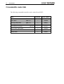
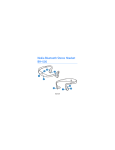
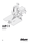
EasySolder Version 1.3 (Januar 1999) User’s Manual Copyright 1998 LPKF Laser & Electronics AG All Rights Reserved LPKF Laser & Electronics AG Osteriede 7 30827 Garbsen Germany Tel.: 49-(0)5131 7095 0 Fax: 49-(0)5131 7095 90 e-mail: [email protected] Internet: http://www.lpkf.de 2 User's Manual Information in this document is subject to change without notice. No part of this document may be reproduced or transmitted in any form or by any means, electronically or mechanically, including photocopying, recording, or by any information storage and retrieval system for any purpose, without the express written permission of LPKF. Every effort has been made to supply complete and accurate information. However, LPKF assumes no responsibility for its use, nor for any infringements of patents or other rights of third parties which would result. 1998 LPKF Laser & Electronics AG. All rights reserved. Edition: 16.12.99 Order No. 104 424 User's Manual 3 Table of Contents Introduction 4 Conditions 4 Scope of delivery 4 Technical Data 5 LPKF MiniPress .................................................................................................. 5 Solder mask ......................................................................................................... 5 Procedure 6 Preparing the Gerber data in CircuitCAM............................................................. 6 CircuitCAM 2.x ............................................................................................ 6 CircuitCAM 3.0 ............................................................................................ 6 Preparing the solder mask for milling ................................................................... 7 Milling the solder mask with BoardMaster ........................................................... 7 Prepare the finished milled board.......................................................................... 7 Prepare the Press sheet......................................................................................... 8 Prepare the solder mask ....................................................................................... 8 Fix the solder mask on the PCB ........................................................................... 8 Assemble the press............................................................................................... 8 Adjust the pressing pressure................................................................................. 9 Hardening in the oven .........................................................................................10 Cooling down .....................................................................................................10 Production Procedure LPKF AutoContac combined with LPKF EasySolder .......11 Consumable materials 12 Index 13 4 User's Manual Introduction LPKF EasySolder is a process for the production of PCB prototypes by means of which a previously milled solder mask can be glued permanently onto a board. This facilitates the soldering process especially for PCBs with SMT assembly / assembled components . The LPKF MiniPress needed for this process can handle boards up to the size of 180 x 120 mm. Conditions To be able to use the LPKF EasySolder process you need a reflow-oven, • which can be heated up to 175°°C and • which has a minimum internal space of 140 x 350 x 250 mm (H x W x D). Scope of delivery Check if the delivered goods are complete. The scope of delivery comprises: 1x 1x 1x 2x 10 x 10 x 2x 4x 3x 1x 1x 1x 1x 1x 1x 1x LPKF MiniPress Torque wrench, complete Socket ½“ 19mm Pressing metal sheet DIN A4 Pressing cardboard cushion DIN A4 Solder mask DIN A4 Press sheet DIN A4 Drill underlay material DIN A4 Micro Cutter Glue stick Tape Pair of working gloves Configuration disk for LPKF CircuitCAM Scalpel Scalpel knife This user manual User's Manual Technical Data LPKF MiniPress dimensions: weight: max. pressing surface: 140 x 350 x 250mm (H x W x D) 16kg 180 x 120mm Solder mask material: glue: Note: Polyimide Acrylic, flame-retarding The solder mask is provided with a flame-retarding acrylic glue. The flame proofing agent does not contain poly-brominated diphenyls. Therefore a fire will not cause toxic or aggressive gases. The solder mask can withstand a solder bath temperature of 288°C for 5 minutes. The electrical characteristics comply with the IPC requirements. 5 6 User's Manual Procedure Preparing the Gerber data in CircuitCAM CircuitCAM 2.x On the disk contained in the delivery you will find insulating and output jobs prepared for the generation of milling data for the solder mask as well as the corresponding format reference for CircuitCAM. SolderMaskCut (UserInsulate) SolderMaskOut (UserDataOutput) SolderMaskTool (UserDataFormat) In menu FILE select function MIX SCRIPT, in order to open the file „mask.scr“ on the disk and to load the jobs SolderMaskCut and SolderMaskOut as well as the format reference SolderMaskTool. The insulating job SolderMaskCut expects the two layers SolderMaskSold and SolderMaskComp. Therefore allocate the corresponding Gerber files to these layers when reading in the production data. During aperture definition take care that the pads to be milled do not increase in size by the diameter of the milling cutter when this tool is used. Use the job SolderMaskOut for the handing over to BoardMaster . CircuitCAM 3.0 Copy template file EasySolder.cat from the supplied disk to the New_Templates folder. Start CircuitCAM and open the format template Easysolder.cat with the NEW submenu from the FILE menu. Import the solder mask files (Gerber) using FILE; IMPORT, OPEN; where either SolderMaskTop or SolderMaskBottom is indicated for the layer. For the isolation (EDIT, INSULATE, JOB) the jobs InsulateDefaultTop and InsulateDefaultBottom are used. The corresponding button can also be found in the PROTOTYPING toolbar. Isolate component side Isolate solder side To export data, select LPKFCircuitBoardPlotter from the EXPORT submenu of the FILE menu. The file created will be saved to the working subfolder under the same name as the CircuitCAM file, but with the file extension .LMD. The corresponding button can be found in the toolbar PROTOTYPING. Export LPKFCircuitBoardPlotter User's Manual 7 Preparing the solder mask for milling 1. Cut the solder mask to the appropriate size so that it is by 10 mm bigger at each side than the PCB layout. 2. Use the two drill underlay material materials for milling in order to avoid damaging the milling tool! 3. Please check whether the solder mask is covered with a protective film. If it is, then remove the film. 4. Place the solder mask with its mat side downwards onto the two drill underlay materials. 5. Fix the solder mask with the tape contained in the delivery. When fixing the film, make sure that the solder mask covers the board flat and even. Note for milling the circuit board Make sure that at each side the PCB basis material size is by 10 mm bigger than the layout to be milled so that the solder mask can be fixed on the PCB more easily. Milling the solder mask with BoardMaster Settings: Tool: Unimill100 micro-milling tool Tool diameter: 0.15mm R.P.M.: 40.000 (20.000) min-1 Speed: 10 (5) mm/s Values in brackets apply for circuit board plotter with DC motor! 1. Adjust the milling depth on that part of the solder film border area which is not used: With the motor switched on you should mill a rectangle of 2x2 mm by means of the traverse keys in BoardMaster . 2. Switch on the vacuum system. 3. Start the milling process using the data prepared by CircuitCAM. 4. At the end of the milling process check whether all pads have been cut out. If this is not the case, start the milling process again. Prepare the finished milled board Clean and grind the board as described in the manual for the circuit board plotter in order to achieve the correct adhesion of the solder mask to the board. 8 User's Manual You should clean the board again with a solvent even shortly before the pressing process. Prepare the Press sheet Use a pair of scissors to cut the PRESS SHEET to the size of the PCB to keep the material used as small as possible. After the pressing process the press sheet can be reused around 10x. Prepare the solder mask Before the pressing process pre-dry the solder mask in an hot air oven for 10 minutes and at 100 °C. Fix the solder mask on the PCB To keep the solder mask in place on the board we recommend to fix it by using glue to put two small glue spots on the board. Glue spots PCB Layout area Solder stop film Make sure that the glue spots are outside of the layout area! Assemble the press 1. 2. 3. 4. 5. 6. 7. For assembling the press with the PCB loosen the four clamping nuts and pull the top of the press off using the handle. Put the following objects one after another and centered on the pressing surface of the bottom part: the pressing cardboard cushion for the bottom part the pressing metal sheet for the bottom part for double-sided assembled boards: the press sheet for the bottom of the PCB the PCB with the solder mask(s) the press sheet for the top of the PCB the pressing metal sheet for the top part the pressing cardboard cushion for the top User's Manual Now put the top part of the press again on the bottom part. The. LPKF MiniPress should now be assembled as follows: Pressing cardboard cushion Pressing metal sheet Press sheet PCB with solder mask Pressing metal sheet Pressing cardboard cushion one-sided assembled board: Pressing cardboard cushion Pressing metal sheet Press sheet PCB with solder mask Press sheet Pressing metal sheet Pressing cardboard cushion double-sided assembled board: Adjust the pressing pressure To do this, screw the four nuts on the threaded bolts.. 9 10 User's Manual In order to generate the necessary pressing pressure for the solder mask to be glued on screw the four nuts tight and crosswise until the corresponding clamping torque is reached according to the following table: Clamping torque per screw PCB size 29Nm 180 x 120mm 22Nm 160 x 100mm 13Nm 100 x 100mm You can use the following formula for determining the clamping torque for PCB sizes not stated in the table: Clamping torque per screw = 0.00135 Ÿ PCB size Note: The clamping torques as explained above are corresponding to a pressing pressure of approx. 250 N / cm². Hardening in the oven In addition to pressure an increased temperature is needed for hardening the glue on the solder mask. Put the press for a period of 2 hours into a reflow-oven. Temperature: 175°C, do not pre-heat! Please note that the period of two hours ( heating up and reaching the temperature within the press ) relates to the heating in a reflow-oven. Other periods of time may result when using a different oven. Cooling down Let the press cool down in the opened reflow-oven. Attention, Danger of Burns ! Make sure that the press is cooled down before taking it out of the reflow-oven and opening it. Use the gloves supplied with the delivery for taking thepress out of the oven! The gluing process is now finished. User's Manual 11 Production Procedure LPKF AutoContac combined with LPKF EasySolder The solder mask process LPKF EasySolder can also be used in combination with the through-plating process LPKF AutoContac. The procedure is as follows: • Before through-plating the board, put the solder mask onto the board by means of the pressing process. • Allow the circuit board which is now provided with the solder mask to cool down and then clean it thoroughly using a solvent. • Then proceed with the through-plating process with LPKF AutoContac in the way described in the LPKF AutoContac manual. • Finish all through-platings and harden the board in the oven. When the board has cooled down, apply a solder resin in order to improve the solderability. * Note when using LPKF MiniPress: There must be alignment holes available as the board will be machined on the circuit board plotter after the pressing process. Reduce the distance of the pilot pins of the circuit board plotter according to the working area of the LPKF MiniPress. There are no limitations for the application of the solder mask when the LPKF MultiPress is being used, i.e. it is possible to use the A4 basis material with the normal distance for alignment holes. 12 User's Manual Consumable materials The following consumable materials can be ordered from LPKF:: Item Quantity Order number Solder mask DIN A 4 10 104178 Press sheet DIN A 4 1 106084 Pressing metal sheet DIN A 4 1 104421 Pressing cardboard cushion DIN A 4 10 104420 Drill underlay material 1 101051 Micro cutter 3mm shank 1 100889 Micro cutter 1/8“ shank 1 100890 Scalpel knife 1 104441 DIN A 4 User's Manual 13 Index A Acrylic glue.............................................. 5 Adjust the pressing pressure..................... 9 Assembling the press................................ 8 B Boards Size ...................................................... 4 C CircuitCAM 2.x ........................................................ 6 3.0 ........................................................ 6 Clamping nuts.......................................... 8 Clamping torque ...................................... 9 Consumable materials............................. 12 Cooling down ........................................ 10 IPC requirements..................................... 5 L LPKF EasySolder .................................... 4 LPKF MiniPress Dimensions........................................... 5 P PCB prototypes ....................................... 4 PCB size.................................................10 Polyimide ................................................ 5 Press sheet............................................... 7 R Reflow-oven Internal space ....................................... 4 Temperature......................................... 4 Responsibility .......................................... 2 D S Double-sided assembled board ................. 9 Finished milled board Prepare ................................................. 7 Scope of delivery..................................... 4 Solder bath temperature........................... 5 Solder mask Fix on the PCB..................................... 8 Preparing for milling............................. 7 H T Hardening .............................................. 10 Tool Settings ................................................ 7 F I Insulating and output jobs ........................ 6