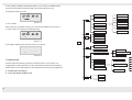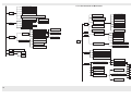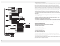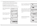
1
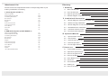
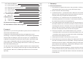
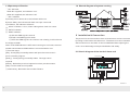
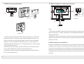
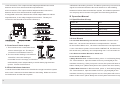
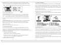
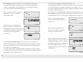
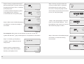
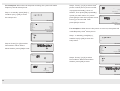
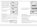
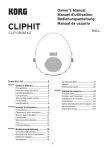
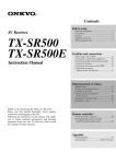
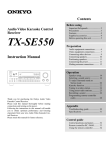
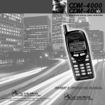
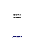
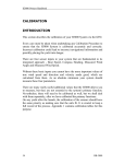
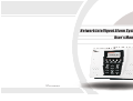
Network Intelligent Alarm System
User’s Manual
V1.0
P/N:350310000868E010
Attachment List
Directory
Please check the complete attachment in the package before your
Ⅰ Summary
(1)
making installation and setting.
1.1
Brief introduction
(1)
1.Alarm System (433SF-1)
1.2
Unit introduction
(3)
1.3
Spares specification
(4)
1.4
Sketch diagram of system running
(5)
Alarm Unit (433SF)
1pc
Wireless Remote Controllers
2pcs
2.2K Sewing Resistances
4pcs
M4 45Screws
4pcs
M3 8Screws
1pc
Stopper
4pcs
6 code connector base
Ⅱ Installation & Connection
(5)
2.1
Sketch diagram of the back of alarm unit
(5)
1pc
2.2
Wall-mounting installation
(6)
3 code connector base
1pc
Sketch diagram of connecting interface
(7)
1pc
2.3
User’s Manual
Phone Line
1pc
2.4
Wired detectors installation
(7)
Adapter
1pc
2.5
Interface of alarm output
(8)
2.6
Enroll wireless detectors
(8)
2.GSM Alarm System (433SF/GSM/S-1)
Alarm Unit (433SF/GSM/S)
1pc
Wireless Remote Controllers
2pcs
2.2K Sewing Resistances
4pcs
M4 45Screws
4pcs
M3 8Screws
Ⅲ Operation Manual
(9)
3.1
Specification of beep
(9)
1pc
3.2
Arm/ Disarm
(9)
Stopper
4pcs
3.3
Alarm & alarm process
(10)
6 code connector base
1pc
3 code connector base
1pc
3.4
Remote operation
(13)
User’s Manual
1pc
3.5
Events logs & Query
(13)
Phone Line
1pc
Adapter
1pc
12V 1300mAh NI-MH battery
1pc
Ⅳ How to set
(14)
4.1
Index table of setting
(14)
4.2
Operation specification
(19)
4.3
How to set phone/CID
(19)
4.4
How to set Date
(30)
4.5
Arm/ Disarm Timer
(31)
4.6
Zone List
(34)
4.7
Zone Attributes
(36)
4.8
Modify pin
(39)
4.9
How to set delay
(41)
4.10 How to set Report
(48)
4.11 How to make enrollment
(53)
4.12 How to enroll wireless siren pin
(56)
4.13 Voice Record
(57)
4.14 Factory default
(58)
4.15 Installer Set
(59)
Ⅴ Technology Parameter
(61)
Alarm unit
(61)
Ⅵ Maintenance
(61)
5.1
Ⅰ Summary
1.1 Brief Introduction
1. LCD interface: English LCD screen, easy operation, working
running and alarm procure are of easy and simple usage.
2. Built-in antenna and latest design.
3. 16 wireless zones: 1-16 wireless zones. Each zone can enroll 3
detectors. Be compatible with the wireless detectors from our
company and easy to expand the wireless zones.
4. 4 wired zones: 13-16 wired zones. Act on NO/ NC alarm by
6.1
Regular test
(61)
connecting with end-of-line resistor. It owns the functions of clew
6.2
Clean the alarm unit
(61)
for wired zones’ trouble and compelling Arm.
Ⅶ Exclude the Simple Troubles
(61)
Ⅷ The limitation of this alarm system
(62)
5. The modes of Multi-user and Mono-user can be exchanged. On
the mode of Multi-user, 8 remote controllers: 8 remote controllers
are assigned to 8 users. CID alarm center can identify the different
users by the pin of remote controllers; On the mode of Mono-user,
Foreword
Appreciate for your choosing this alarm system, which is reliable for its
the user can Away Arm/ Home Arm the whole system.
6. 8 remote controllers: on the mode of Mono-user, 8 remote
certificates and multifunction.
controllers share 1 main user; on the mode of Multi-user, 8 remote
It adopts the most advanced technology of digital sensor and
controllers refer to 8 users and the alarm center can distinguish
controlling. It is a kind of intelligent alarm control system, aggregated
the directions from different users.
with the features of Burglar, Anti-fire, Anti-gas, etc. Compatible with
7. 8 alarm phone numbers can be set for users or CID.
CONTACT ID agreement enables the alarm system expanded usage
8. Zone attributes can be set according to the attributes of the alarm
and stronger compatibility. With the excellent appearance and
unit and 16 wireless zones. On-spot Alarm, linkage output and
powerful function, it can be widely used at home, community, financial
wireless siren are for option. Individually setting to each zone is
office and office building, etc.
also enabled. Zone attributes: 7 attributes are Burglar, Perimeter,
To make sure the normal usage, please read the user’s manual before
Duress, Panic, Fire, Gas and Medical.
your operation. Our company retains the right to modify and explain the
9. Easy enrollment: Wireless detector, remote controller can be
User’s Manual. Moreover, modified specification won’t be informed
enrolled with the alarm system automatically. Each zone / remote
specially.
controller can be enrolled and delete enrollment automatically &
independently.
1
10. 20s voice record: Record / Playback are easy. 20s record can
24. GSM + PSTN alarm. The user can choose GSM wireless alarm or GSM
be re-recorded at freedom.
11. The pin management: 1 installer’s pin, 1 master’s pin, 8 users’
pins and Duress pin (the Duress pin is plus “1” to the last number
of master’s pin or user’s pin) (8 groups of user’s pins are valid on
wireless with PSTN wired alarm together.
25. AC/ DC: Ext 220V voltage and inner with rechargeable batteries.
1.2 Unit introduction
the mode of Multi-user only).
12. Two groups of Timer Arm/ Disarm: to make two groups of Timer Arm/
LCD display
Disarm according to the working day and resting day. Each group of
Timer Arm/ Disarm has a regular time to be set (Each group of Timer
DC
Arm
Alarm
PSTN
GSM
Indicator
Arm/ Disarm refers to one user on the mode of Multi-user).
13. Queried: It can record and query the 30 logs of alarm, including Away
MIC
Arm, Home Arm, Disarm, Line-cut, Zone Arm, Zone Disarm, low-power
of Zone, the alarm time and the alarmed zone.
14. Support alarm report, the zone list of alarm phone, Arm/ Disarm
Horn
Query
Set
OK
Reset
1
2
4
3
5
6
7
8
9
*
0
#
information and report for Self-testing.
15. Communication time can be set as 00-99 hours. It supports the alarm
Picture 1 Sketch diagram of unit
unit and alarm center, timer communication with the related user.
16. Delaying Alarm/ Arm time can be set as 000-255 seconds,
17. The alarm sound duration can be adjusted as 01-99 minutes.
18. Circulated dialing times and ringing times can be adjusted as 03-15 times.
19. Siren: the unit has equipped with inner siren. Meanwhile, it can connect
with wired siren in wire terminal and program with wireless siren
20. Three levels of alarm volume are optional.
21. Alarm line-cut: If the line of wired detector is cut, the alarm system will
Picture 2 LCD View
make alarm at once. Meanwhile, if the phone line is cut, the unit will send
the warning tone.
22. NO and NC relay alarm output are suffered. Also 12V 150mA AC is
provided.
23. Remote operation: It can make the following actions by phone remotely,
such as Arm/ Disarm, monitor indoor, turn on-site alarm on the remote
Picture 3 Sketch diagram in standby
phone.
2
3
1.3Spares specification
1.4 Sketch diagram of system running
① “DC” indicator
When DC supplied, the indicator is on.
,.$
/0
1*+
2*+
!"
#$
%&'
()'
3*+
4*+
5*+
6*+
7*+
8*+
*
Yes
0
#
No
When AC supplied, the indicator is off.
② “Arm” indicator
A)In Away Arm or Home Arm, the indicator will be on.
DC
B)In Arm delay, the indicator will flash once per 2 seconds.
Arm
C)In Disarm, the indicator will be off.
Alarm
Query
Set
PSTN
GSM
OK
Reset
1
2
3
4
5
6
7
8
9
*
0
#
③ “Alarm” indicator: It is on, when making alarm. And vice versa.
④ “PSTN” indicator
⑤ “GSM” indicator:
A) ON: the GSM signal is normal.
Ⅱ Installation & Connection
B) Flash: the GSM signal is weak.
The phone line and connection wires of wired zones can be connected
C) OFF: the GSM signal is in trouble or not existing, it will influence
by hiding on the back of the alarm unit. The alarm unit can be installed
the usage of GSM.
wall-mounted or on the desk. It can be installed without opening the
Note: if the GSM indicator is OFF after inserting for 3 minutes, the user
cover. It has advantage of simple installation and safety.
should check whether GSM module is connected well or not.
⑥ Function keys:
[Set] : Press [Set] in standby status and input the correct user’s
pin to enter the program.
2.1 Sketch diagram of the back of alarm unit
Wiring terminal
[ Query ] : Press [ Query ] in standby status. The logs can be
inquired.
[ Reset ] : Delete the previous inputted or exit to previous status.
[ OK ] : Confirm what users inputted
⑦ Number key: Be used to set and Arm/ Disarm.
Battery case
Tamper switch
Wiring slot
4
Picture 1
5
2.2 Wall-mounting installation
2.3 Sketch diagram of connecting interface
Upper mounting hole
Phone connection
80mm
M4x45
105mm
80mm
PHONE
LINE
Under mounting hole
Phone
Picture 2
Picture 3
Picture 5
ON
K1
OFF
SW1
Volume: L-H
Battery switch
( OFF )
( On )
ON
K2
OFF
Line-cut test switch
( OFF )
( On )
Note:
M3x8
Picture 4
1) Take the hang-up board from the back of the alarm unit, and fix four
plugs and one M4×
45 screws on the wall accordingly (as Picture 2).
2) Draw the one set of 6 pin Wired Holder and two sets of 3 pin Wired
Holders. Connect with power and wired zones, etc. Then insert the
related Wired Pillar and Phone Line. Hang the alarm unit on the screws
as pictures 6 and Picture 7.
3) After finishing connecting, pull the three holes of the back of alarm
unit up the related holes of hang-up board (as Picture 3).
4) Tighten the bottom of hang-up board with the back of alarm unit by
M3×
6
8 screw (as Picture 4).
①The power of detector suffered by the alarm system should not more
than 12V power (or ≤150mA). Otherwise, it should be suffered with 12V
backup power EXT.
②When there are not wired zones connected, the wired zones should
also be connect with end-of-line resistor to make sure the alarm system
working normally.
2.4 Wired detectors installation
Wired zones adopt AD converting technology and can be connected with
2.2K end-of-line resistor, which make sure the reliability of alarm system.
The power of wired detector was suffered by 12V output terminal of alarm
system. The output terminal of every detector connects with the connection
and GND of the corresponding zone by end-of-line resistor as picture
showing:
7
1.NO connection: The output terminal adopts paralleled connection
2.Wireless transmitting function: The alarm system may not receive the
between end-of-line resistor and NO output detector.
signal from wireless detectors due to far distance or wall-shading
2.NC connection: The output terminal adopts tandem connection
between wireless detector and alarm system, the wireless repeater from
between end-of-line resistor and NC output detector.
our company can be chosen to lengthen the transmitting distance.
3.Integrated connection: When there are NO output detector and NC
output detector, it can adopt integrated connection. The ways of
Ⅲ Operation Manual
connection are showed as Picture a & Picture b:
3.1 Specification of beep
A short “Di”
Arm
Two short “Di”
Disarm
A short “Di” per 1s
Delay Arm
Two quick short “Di… Di” per 1s
Alarm Delay
A long “Di” per 15s
Low power
Three quick short “Di…Di…Di” per 1s
Phone line-cut
3.2 Arm/ Disarm
3.2.1 Armed/ Disarmed by the remote controller. On the mode of
Multi-user, 1-8 remote controllers are corresponded to 1-8 users.
2.5 Interface of alarm output
1. This interface is to connect the wired
siren or alarm light, etc. The way of
connection is showed as Picture c.
2. The connection loading is 1A 120V AC/
1A 24V DC, when the loading of
controlled circuit is too large, it should be
suffered with power independently to avoid destroying the alarm
system. Please visit Picture d:
2.6 Enroll wireless detectors
1.Install the enrolled detectors in the effective range from alarm system
as the user’s manual of wireless detector describing. Make sure to test
for the detector and the alarm system.
8
On the mode of Mono-user, 1-8 remote controllers are corresponded to
1 user. If the alarm systems connect with CONTACT ID, the alarm center
will record every master by its corresponding user. It is convenient to query.
3.2.2 Shortcut of Arm/ Disarm in alarm unit
On the mode of Mono-user:
A)Away Arm shortcut: In Disarm status, press “4” until hearing beep of
“Di”. Then release it. Input the master’s/user’s pin and [OK] on the
interface of entering. If the pin input is correct, the system will enter a
status of Away Arm. (When Delay Arm of the system was set to be 0s)
B)Home Arm shortcut: In Disarm status, press “4” until hearing beep of
“Di”. Then release it. Input the master’s/user’s + [#] and [OK] on the
interface of entering. If the pin input is correct, the system will enter a
status of Home Arm. (When Delay Arm of the system was set to be 0s)
9
C)Disarm shortcut: In Arm or Alarm status, press “4” until hearing beep
3.3.1 Alarm attributes
of “Di”. Then release it. You are required to input the master’s/user’s and
When the zone is set as “Burglar” or “Perimeter”, the intruding alarm
「OK」. Input the correct pin and OK and the system enters Disarm status.
won’t be made except the alarm system is in the status of Arm. And it
will be influenced by Delay Alarm Time. But for the Panic alarm, such as
Tamper Alarm, it will not be influenced by Delay Alarm Time whatever the
DC
Arm
Alarm
Query
Set
PSTN
GSM
OK
Reset
1
2
3
4
5
6
7
8
9
*
0
#
status the alarm system is.
When the zone is set as “Panic”, “Fire”, “Gas” or “Medical” etc, the system
will make alarm once the zone is triggered.
“Duress” is for special situations, such as there is required to make alarm
On the mode of Multi-user:
silently on spot.
A) Away Arm shortcut: In Disarm status, press “4” until hearing beep
of “Di”. Then release it. Input the corresponding master’s/user’s and 「
OK」 on the interface of entering. If the pin input is correct, the system
DC
Arm
will enter a status of Away Arm. (When Delay Arm of the system was set
to be 0s)
Alarm
Query
Set
PSTN
GSM
OK
Reset
1
2
4
3
5
6
7
8
9
*
0
#
B) Disarm shortcut: In Arm or Alarm status, press “4” until hearing beep
of “Di”. Then release it. You are required to input the corresponding
master’s/user’s and 「OK」. Input the correct user’s pin, the system
enters Disarm status.
Note: The pins are referred on Term of 4.8.
3.2.3 Timer Arm/ Disarm
Set Timer for Arm or Disarm accordingly. When the system runs to the
setting time, it will enter Away Arm/ Disarm automatically. (On the mode
of Multi-user, each group of Timer Arm/ Disarm is corresponded to one user.)
3.2.4 Remote Arm/ Disarm
1) Remote Arm/ Disarm on phone
Please refer to Term of 3.4 remote operation.
2) Remote Arm/ Disarm on GSM (GSM module should be equiped)
Please refer to the User’s Manual of GSM Module
3.3 Alarm & alarm process
10
Picture 8
3.3.2 Alarm Phone
When the alarm system receives the signal from detectors, it will activate
alarm at once and dial the set phones. The user will hear the recorded
voice on the phone. In the end of record, you will hear “Di”. You can
operate the alarm system on the key of phone within 5s (as Picture 8).
If the alarm won’t process within 5s, the alarm dialer will go on. If this user
have valid operation through phone, the alarm system will continue to dial
next phone. And won’t dial this user’s again.
Input “2#” to eliminate the alarm, the alarm system will continue to dial
other pre-set phones.
11
3.3.3 The alarm center
3.4 Remote operation
The alarm system sends the alarm signal to the alarm center; the center
The users can call the phone number that alarm unit connected to set
will reply the alarm system with the confirmed signal. If receiving the
remotely. The user dials the phone number that alarm unit connected,
confirmed signal from the alarm center, it won’t dial alarm center again.
and waits for ring times arrives, the user will hear a DI, then have to input
Or else, it will dial alarm center continually until the dial times arrives.
the user’s pin and #, if the user’s pin corrects, you can set below..
The alarm information is displayed and handled by the alarm center on
the computer.
3.3.4 The process of making alarm (Picture 9)
PSTN
Picture 12
3.5 Events logs & Query
3.5.1 The alarm events are: Alarm, Away Arm, Home Arm, Disarm, phone
line-cut, Arm/ Disarm of detectors, Low voltage, battery restore, etc.
3.5.2 Query
DC
Arm
Alarm
Query
Set
PSTN
OK
Reset
1
2
Press [ Query ] in standby to inquiry the alarm logs (30 pieces at most).
GSM
If the total logs exceed 30 pieces, the oldest record will be deleted. Each
3
4
5
6
7
8
9
*
0
#
piece of record is signed as “nx” (“x” is the number of alarm logs).
KS-868E (433.92MHz)
Users can read the logs with pressing [*] or [#] .
For example, when the alarm system is in standby status, you can
press [Qurey] to enter the query screen.
Picture 9
12
Picture 1
13
Press [OK] to display the specifications: 18:18 July 1st Wednesday,
the first zone makes Perimeter Alarm as follows as Picture 2:
press [#] to read next one
st
The 1 phone number
Set the phones
st
The 2 phone number
Report for alarm information
Phone
st
The 4 phone number
Picture 2
3.5.3 Trouble
st
The 3 phone number
Set the phone zones list
st
The 5 phone number
When there is a trouble existing, the screen will display as Picture 3:
Set Report for Arm/ Disarm
it means there is trouble on the wired zone.
Set Report for self-testing
Disarm
Clock
st
The 8 phone number
st
Arm for the 1 Timer
Fault
Timer
st
Disarm for the 1 Time
nd
Arm for the 2 Timer
Picture 3
nd
Disarm for the 2 Timer
Set
Press [#] to display which wired zone is in trouble.
Away Arm zones list
Zone
Home Arm zones list
Alarm on-spot for option
Fault
13
14
15
16
Set the attribute of the alarm unit
Picture 4
Integrated alarm output for option
Wireless siren for option
Attribute
Burglar
01 zone attribute
Ⅳ How to set
Alarm on-spot for option
Perimeter
Duress
02 zone attribute
Please read the following manual carefully before your usage. It is
Panic
Integrated alarm output for option
suggested to make operation under the professional person guidance.
Fire
Note: We are not responsible for the default caused by wrong operation.
Set the attributes of 16 zones
Gas
Wireless siren for option
4.1 Index table of setting
Medical
4.1.1 On the mode of Mono-use
Installer' pin
Code
Master's pin
14
15
4.1.2 On the mode of Multi-user
Set time of Delay Alarm
Set time of Delay Arm
Set time of Alarm sound
Delay
Set remote ringing times
The 1 st phone number
Set the phones
Set the circulated dialing times of alarm receiving phones
nd
The 2 phone number
Report for alarm information
Set time of Timer Communication
rd
The 3 phone number
Mode of Mono-user
System-setting modes for option
Report
th
The 4 phone number
Set the phone zone list
Mode of Multi-user
Relay Report
Phone
Controlling switch of Alarm Center
th
The 5 phone number
Set Report for Arm/ Disarm
Switch of compulsory Arm
Enroll the detector of the1 st zone
st
Enroll the 1 detector
th
Set Report for self-testing
The 8 phone number
nd
Enroll the detector of the 2 zone
Clock
st
Arm for the 1 Timer
nd
Enroll the 2 detector
Detector enroll
Set Arm/ Disarm Timer
st
Timer
Disarm for the 1 Timer
th
Enroll the detector of the 16 zone
Enrollment
rd
Enroll the 3 detector
nd
Arm for the 2 Timer
st
Enroll the 1 remote controller
nd
Enroll remote controller
nd
Enroll the 2 remote controller
Disarm for the 2 Timer
Set
st
Users' list of the 1 Timer Arm/ Disarm
Set zones list of the user
nd
Users' list of the 2 Timer Arm/ Disarm
rd
Enroll the 8 remote controller
Siren
Code of wireless siren
Playback
st
Away Arm zones list of the 1 user
Zone
nd
Away Arm zones list of the 2 user
Rec/ Play
Record
th
Away Arm zones list of the 8 user
Alarm on-spot for option
Set the attribute of the alarm unit
Attribute
Integrated alarm output for option
Wireless siren for option
Burglar
Perimeter
01 zone attribute
Duress
02 zone attribute
Alarm on-spot for option
Panic
Fire
Integrated alarm output for option
Set the attributes of 16 zones
Gas
Medical
Wireless siren for option
16
17
4.2 Operation specification
* It adopts Menu to guide the users. In the standby status, you can press
[Set] and the alarm unit will require to input the user’s pin and OK.
If the user’s pin input is wrong with three times continually, the alarm
Installer' pin
will be activated for one minute. Any operations are not allowed during
st
the 1 user's pin
Master's pin
that time. The alarm will be locked 1 minute. After one minute, the user
nd
Code
the 2 user's pin
can press [ Disarm ] by remote controller to unlock the alarm system.
User's pin
* Right operation with a short “Di”; Wrong operation with a long “Di”.
th
the 8 user's pin
Set time of Delay Alarm
* The alarm system will exit the standby status, if there is no operation
Set time of Delay Arm
within 60s.
Set time of Alarm sound
* Pressing [ Reset ] means coming back to the previous menu or deleting
Set remote ringing times
the previous input.
Set the circulated dialing times of alarm receiving phones
* When the users set the alarm system, the users can press [*] , [#]
Delay
Set time of Timer Communication
ON:Mode of Mono-user
and [OK] key to reach the menu they want.
OFF:Mode of Multi-user
* The setup is available only when the system is in standby. During the
System-setting modes for option
Report
Relay Report
set, the system won’t respond any alarm. After exit from set, the system
Controlling switch of Alarm Center
will enter Disarm. The users have to arm accordingly if need.
Switch of compulsory Arm
st
Enroll the 1 detector
st
Enroll the detector of the1 zone
nd
Enroll the detector of the 2 zone
nd
Enroll the 2 detector
4.3 How to set phone/ CID
There are 5 sub-menus in Phone menu, as follows:
Detector enroll
Enrollment
* Set alarm phone number
th
Enroll the detector of the 16 zone
rd
Enroll the 3 detector
* Set alarm panel report
st
Enroll the 1 remote controller
Enroll remote controller
* Set zone list for alarm phone
nd
Enroll the 2 remote controller
* Set arm/disarm report
* Set self inspection report
rd
Enroll the 3 remote controller
Siren
Address pin of wireless siren
Playback
Record/ Playback
Record
4.3.1 Set the alarm phones
* There are 8 alarm phones can be set. They can be set as Normal
Phones or CID Phones. To insure the priority of CID, please set the CID
alarm phone as the 1st alarm phone.
* 28 numbers can be included in the phone. The interface will turn a new
page when input 11 digits of number.
18
19
* Inputting [*] for 2s pause, the LCD screen will show “└”.
* Press the [phone numbers] + [OK]to setting the Normal phones;
Press [phone number] + [#] + 4-digit CID account] to set the CID
phone number. The 4-digit CID account should be in the range of
Step 4: Press [12345678] + [#] + [ 6789 ]
0000~9999. Input “#” , the LCD screen will show “┘” .
+[OK] . If it sets successfully, the LCD
For example 1: The alarm system is connected with exterior line
display will show PASS as Picture 7.
Set
Telephone
1
Picture 6
directly. Now set the mobile phone number “12345678” in the 1st
alarm phone for CID, CID account 6789 Please read the following steps:
Set
Telephone
1
Step 1: In standby, press [ Set ] + [
Step 5: To set the number of “77880088”
installer’s pin ]+ [OK] to enter the
as the second alarm center. Press [*] or [
setup menu
#] to select “2” as Picture 8. It means
Pin
Picture 1
Step 2: Press [*] or [*] to select
Phone Menu. When Phone Menu
flashes, press [OK] to enter.
3
Set
Telephone
Clock
Timer
Zone
Attribute
Pin
Delay
the 2nd phone number to be set when “
Picture 7
Set
Telephone
2
2” flashes as Picture 9-10, press [OK]
Report
Enroll
Siren
Record/ Playback
to enter.
Picture 8
Set
Telephone
Picture 2
2
Set
Telephone
Picture 9
1
Step 6: After inputting the numbers,
Picture 3
Step 3: It means the 1st phone
Set
Telephone
number to be set when “1” flashes,
Set
Telephone
press [OK] to confirm and the screen
2
will display as Picture 11.
Picture 10
1
press [OK] to enter.
Set
Telephone
Picture 4
2
Set
Telephone
Picture 11
1
Picture 5
20
21
For example 2: The alarm system is connected with exchange line.
The zone report: Burglar and Tamper of detector, etc.
The “0” is required before phone number. Now set the mobile phone
Self-inspection information: Low power of alarm unit, battery restoration,
number “12345678901” as the third phone. There should be a pause
AC-off, AC restoration, low battery of detector, zone Bypass, zone
exchanger. Please read the following steps:
restoration, GSM communication failure, GSM communication restoration
and Timer communication, etc.
Step 1: In the phone menu, press [*] or
In the Phone menu, press [Set] key repeatedly to select the sub-menu,
Set
Telephone
For example 1: When there is alarm occurring on the alarm unit, the alarm
[#] to select “3”, when “3” flashes,
3
unit will Report it by the 2 nd alarm phone. The operation is as follows:
press [OK] to enter.
Picture 1
Set
Telephone
Step 1: In standby, press [Set] + [
Installer’s pin ] + [ OK ] to enter the
setup menu.
3
Pin
Picture 1
Picture 2
Step 2: Press [ 0 * 12345678901 ] + [
OK]. If the setup is successful, the
Set
Telephone
Step 2: Press [*] or [#] to select
LCD display will show the PASS.Once
3
the numbers is beyond 11 figures, the
Phone Menu. When Phone Menu
next figures will be displayed on
flashes, press [OK] to enter.
next screen.
Set
Telephone
Clock
Timer
Zone
Attribute
Pin
Delay
Picture 3
Report
Enroll
Siren
Record/ Playback
Picture 2
Set
Telephone
!"
Set
#$
Telephone
1
3
3
Step 3: Press [*] or [#] to select the 2
Picture 2
4.3.2 Set the information Report of the alarm unit, the zones list for
related alarm phones, Arm/ Disarm Report and the self-inspection Report.
When there is alarm occurring, “ON” is for Reporting to the alarm phones
and “OFF” is turn off Reporting.
The alarm panel report: emergency alarm activated by remote controller,
Picture 3
nd
nd
phone number (the 2 phone number is
Set
Telephone
programmed ready), when “2” flashes,
2
press [Set] to choose turn on Reporting.
Then press [OK] to make sure and
continue to press [*] to be in ON, to turn
Picture 4
Set
Telephone
on Reporting.
2
emergency alarm of main unit, Tamper alarm of alarm unit, alarm activated
by wrong pin input and duress alarm.
22
Picture 5
23
Step 4: When there is displaying PASS
Step 4: When there is displaying PASS
on interface, it means the setting
is successful.
Set
Telephone
on interface, it means the setting
2
is successful.
Set
Telephone
Zone
1
Picture 5
Picture 6
Set
!"
Telephone
#$
Set
!
"
Telephone
#
$
2
Zone
3
3
1
Picture 6
Picture 7
For example 2: When there is alarm on zone 01, 02, 06 and 12, the
system will dial the 1
st
group of alarm phones. The operation is as follows:
For example 3: When there is alarm occurring on the alarm unit, the
system will send Arm/ Disarm Report by the 3rd alarm phone.
Step 1: In standby, press [Set] +
Step 1: In standby, press [Set] + [
[ Installer’s pin ] + [OK] to enter
Installer’s pin ] + [ OK ] to enter the setup
the setup menu.
menu.
Pin
Pin
Picture 1
Step 2: Press [OK] or [#] to select
Phone Menu. When Phone Menu
flashes, press [OK] to enter.
Set
Telephone
Clock
Timer
Zone
Attribute
Pin
Delay
Picture 1
Set
Telephone
Clock
Timer
Zone
Attribute
Pin
Delay
Report
Enroll
Siren
Record/ Playback
Picture 2
Step 3: Press [*] or [#] to select
Set
Telephone
1
Picture 3
Set
Telephone
Picture 3
Set
Telephone
press [OK] to enter the menu. And
continue to press the zone number 01,
Set
Telephone
flashes, press [OK] to enter.
“1” flashes, press [Set] twice to
reach “ Zones List” menu. Then
Phone Menu. When Phone Menu
1
number is programmed ready), when
Picture 2
Step 2: Press [*] or [#] to select
the 1 st phone number (the 1 st phone
Report
Enroll
Siren
Record/ Playback
Zone 1
3
02, 06, 12.. Then press [OK]
Picture 4
Picture 4
24
25
Step 3: Press [*] or [#] to select the 3 rd
Step 3: Press [*] or [#] to select the
Set
Telephone
rd
Set
Telephone
rd
phone number (the 3 phone number is
3 phone number when “3” flashes,
3
programmed ready), when “3” flashes,
press [ Set ] triple
to reach arm/disarm Reporting menu.
Press [OK] to enter, Press [*]
1
press [Set] twice to reach “Zones
Picture 5
Set
Telephone
Disarm
Home Arm
Away Arm
to choose the ON. Then press [OK]
3
List” menu. Then press [OK] to enter
Picture 3
and continue to press the zone number
01, 02, 03. Then press [OK]
Set
Telephone
Report
3
Picture 6
Set
Telephone
Picture 4
Disarm
Home Arm
Away Arm
3
Step 4; Then press [Set] to reach the
Set
Telephone
Report
Step 4: When there is PASS displaying
menu of “Arm/ Disarm Report”. Then
on interface, it means the setting is
press [OK] to enter, press [*] to choose
successful.
Picture 7
Disarm
Set
!
"
Telephone
#
$
Zone
3
ON. And Press [OK] to confirm
Picture 5
Home Arm
Away Arm
3
Set
Telephone
3
Report
Disarm
Home Arm
Away Arm
3
Picture 8
For example 4: When there is Arm/ Disarm on zone 01, 02, 03, the
Report
Picture 6
rd
system will dial the 3 group of alarm phone. The operation is as follows:
Step 5: When there is PASS displaying
Set
Telephone
Disarm
Home Arm
on interface, it means the setting
Step 1: In standby, press [Set] + [
Away Arm
3
is successful.
Report
Installer’s pin t] + [ OK ] to enter the
setup menu.
Picture 7
Pin
Picture 1
Disarm
Home Arm
Set
Telephone
Away Arm
Step 2: Press [*] or [#] to select
Phone Menu. When Phone Menu
flashes, press [OK] to enter.
Set
Telephone
Clock
Timer
Zone
Attribute
Pin
Delay
33
Report
Report
Enroll
Siren
Record/ Playback
Picture 8
Picture 2
26
27
For example 5: When there is low power existing, the system will make
Report by the 6th alarm phone.
Step 3: Press [*] or [#] to select the 6
th
Set
th
phone number (the 6 phone number
6
Report
is programmed ready), when “6”
Step 1: In standby, press [Set] + [
flashes, Then press [Set] repeatedly (
Installer’s pin ] + [ OK ] to enter
quartic) to reach menu of “l-power”.
the setup menu.
press [OK] to enter the low power menu,
Pin
Picture 1
Set
Telephone
Clock
Timer
Zone
Attribute
Pin
Delay
under-voltage
Picture 7
Set
!
"
Telephone
#
$
Press [*] to choose ON. Then
Report
63
press [OK] to confirm.
under-voltage
Picture 8
Report
Enroll
Siren
Record/ Playback
Picture 2
For example 6: When there is low power on zone 03, the system will
th
make Report by the 6 alarm phone.
Set
Telephone
Step 1: In standby, press [Set] + [
1
Installer’s pin ] +[OK] to enter the
Picture 3
Step 2: Press [*] or [#] to select
setup menu.
Pin
Picture 1
Set
Telephone
Phone Menu. When Phone
Set
Telephone
Clock
Timer
Zone
Attribute
Pin
Delay
6
Menu flashes, press [Set] to enter.
Picture 4
Report
Enroll
Siren
Record/ Playback
Picture 2
Set
Telephone
Step 2: Press [*] or [#] to select
6
Phone Menu. When Phone Menu
Picture 5
Set
Telephone
1
flashes, press [OK] to enter.
Picture 3
Set
Set
Telephone
6
Report
under-voltage
6
Picture 6
Picture 4
28
29
Step 3: Press [*] or [#] to select the 6 th
Set
Telephone
Clock
Timer
Zone
Attribute
Pin
Delay
Set
Telephone
phone number when “6” flashes,
6
Zone
press [ Set ] repeatedly to choose submenu of Zones List. Input zone number
Report
Enroll
Siren
Record/ Playback
Picture 2
Picture 5
03 and [OK] , Then press [Set]
Set
Set
Telephone
repeatedly (quartic) to reach menu
Clock
of “l-power Report”. press [OK] to enter
6
the low power menu, Press [*] to
under-voltage
Report
Picture 3
Picture 6
choose ON. Then press [OK] to
confirm.
Step 2: Input [ 11010515303 ]+ [OK] if
Set
Telephone
the setup is successful, the LCD
Set
Year
Month
Date
Hour
Minute Week
Clock
Report
6
screen will show “PASS”
Step 4: When there is PASS displaying
under-voltage
on interface, it means the
Picture 4
Picture 7
setting is successful.
!"
Set
Set
Telephone
#$
Clock
3
3
Report
6
under-voltage
Picture 5
Picture 8
4.4 How to set Date
This date can be set according to local time. It is very important for Timer
4.5 Arm/ Disarm Timer
Arm/ Disarm and Record of alarm items. This alarm device have equipped
There are two groups of timer. Each group is composed of Arm time and
with real-time module.
Disarm time. The operation is as follows:
xx (2-digits for year) + xx (2 digits for month) + xx (2-digits for day) + xx
The sub-menu under arm/disarm timer,
Time (2-digits for hour) + xx(2-digits for minute) + x(1-digit for week)
1 is first group of arm timer
For example 1: The system will be set to be 15:30 Jan. 5th, 2011. Wed..
2 is first group of disarm time
The operation is as follow:
3 is second group of arm time
4 is second group of disarm time
Step 1: In program, press [*] or [#]
In the multi-user, press [Set] to select the menu of zone list.
to select t “Date”, when the “Date”
x x (2-digits for hour) + xx (2-digits for minute) + 1-7(1-7digits for week)
flashes, press [OK] to confirm.
* On the mode of Mono-user: two groups of Arm time and Disarm time.
Pin
Picture 1
30
It can realize to Arm/ Disarm in different time.
31
* On the mode of Multi-user: two groups of Arm time and Disarm time are
Step 3: Press [*] or [#] to select “2”, “2”
corresponded to 8 users.
is for disarm time of first group. Press [
(Note: The specifications are referred to the term of 4.10.)
OK] to confirm.
!"
Set
#$
Timer
1
3
Note:
Picture 5
ȨThe time set for two groups are not allowed in the same. Otherwise,
Set
the set is not useful.
Step 4: Press [080012345] + [OK]
ȨOn the mode of Mono-user, the system will turn off the function of “
if the set is successful, the LCD will
Zones List of Timer Arm/ Disarm”.
show PASS.
Timer
2
Picture 6
For example 1: On the mode of Multi-user, the first group of timer of
Set
!"
#$
01, 02, 03 zones, from Monday to Friday.
Timer
Arm time is 00:00, Disarm time is 08:00. The operation is as follows:
2
3
Picture 7
Step 1: In program, press [*] or [
Set
#] to select the Timer, if Timer
Step 5: In program, press [Set] to
Menu flashes, press [OK] to
Pin
Timer
Zone
select the Zones List of Timer Arm/
enter.
Picture 1
Set
Telephone
Clock
Timer
Zone
Attribute
Pin
Delay
1
Disarm, if this menu flashes, press [OK]
to enter.
Report
Enroll
Siren
Record/ Playback
Picture 8
Set
Timer
Zone
1
Picture 2
Step 2: “1” is for Arm of first
Picture 9
Set
Telephone
Step 6: Press [ 010203 ] + [OK] if
timer, press [OK] to confirm.
1
the set is successful, the LCD will show
Press [ 080012345 ] + [OK],
if the set is successful, the LCD
will show PASS.
Set
Picture 3
Set
Year
Month
Timer
Zone
1
3
PASS.
Picture 10
Mon.~Sun.
Timer
1
Note: “3” and “4” are for the Arm and Disarm for second group timer. Users
can set accordingly.
Picture 4
32
33
4.6 Zone list
!"
Set
#$
* On the mode of Mono-user: relate to the corresponding Arm/ Disarm
Away Arm
Zone
1
3
Zones List.
* On the mode of Multi-user: relate to the corresponding Away Zones
Picture 5
List of 8 users. Each user’s zones list can be set alternately.
(Note: The selection of modes of Mono-user and Multi-user can be
For example 2: On the mode of Mono-user, set the Zones List of Away
referred on the item of 4.10 “How to set Report”).
Arm: 03, 04, 11, 16 zone; Set the Zones List of Home Arm: 01, 02, 03,
Note: A) The zone number should be fixed to be 2 figures.
14, 15 zone
B) The Zones List of Mono-user & Multi-user modes can be
conserved separately. If the user exchanges the mode, the Zone List
would return to Default State.
For example 1: On the mode of Multi-user, set the Zones List of the 1st
user: 03, 04, 11, 16 zone. The operation is as follow:
Step 1: In program, supposed that the
Mode of Multi-user has been existed on
the item of “Report”. Press [*] or [#] to
select the Zone, when Zone menu
flashes, press [OK] to enter.
Step 1: In program, and in Mode of
Multi-user. Press [*] or [#] to select the
Zone, when Zone menu flashes,
Step 2: In the zone menu, there have “1”
Pin
press [OK] to enter the item of “
Away Arm”.
Picture 1
flashes, press [OK] to confirm, the
Report
Enroll
Siren
Record/ Playback
Picture 2
Step 2: In the zone menu, there is “1”
existing, “1” for zone list. When “1”
flashes, press [ OK ] to confirm, the
Picture 1
Set
Telephone
Clock
Timer
Zone
Attribute
Pin
Delay
Report
Enroll
Siren
Record/ Playback
Picture 2
and “2”, “1” for zone list of Away arm, “2”
for zone list of home arm. When : “1”
Set
Telephone
Clock
Timer
Zone
Attribute
Pin
Delay
Pin
Set
Away Arm
Zone 1
press [ 03, 04, 11, 16 ] + [OK] to set the
zone list of Away home. If the program
sets successfully, the LCD display will
Set
Picture 3
Set
Telephone
show PASS.
Away Arm
Away Arm
Zone
Zone 1
1
press [ 03, 04, 11, 16 ] + [OK] to set the
Zones List. If the program sets
successfully, the LCD display
Picture 3
Set
Telephone
Picture 4
Step 3: In this zone menu. Press [*]
or [#] to select “2” to set the zone list
Set
!
"
#$
Away Arm
will show PASS.
Away Arm
Zone
of home arm, when “2” flashes, press [
Zone 1
3
1
OK] to confirm
Picture 4
34
Picture 5
35
Step 4: Press [ 01, 02, 03, 14, 15 ] + [
Set
If the set is successful, the LCD screen
Burglar
Home Arm
OK] to set the zone list of home arm.
Zone
2
Perimeter Duress
Panic
Fire
Gas
Medical
Away Arm
will show PASS.
Picture 6
Home Arm
Disarm
Set
Home Arm
Zone
2
Note: “√ ”means alarm can be activate when the system is triggered;
“×” means alarm can’t be activate when the system is triggered.
Picture 7
For example 1: When there is Tamper alarm existing, the modes of
on-spot Alarm, Iinkage Output and Wireless Siren are opened.
!"
Set
#$
Zone
Home Arm
2
3
Step 1. In the program, press [*] or [#]
to select Attribute. When Attribute Menu
Picture 8
flashes, press [OK] to enter.
Pin
Picture 1
4.7 Zone Attribute
Set
Telephone
Clock
Timer
Zone
Attribute
Pin
Delay
The system can set output of alarm panel. And set output and attributes
of each zone separately. There are three kinds of output. As follows
On-spot alarm. “1” is ON and “0” is OFF.
Report
Enroll
Siren
Record/ Playback
Picture 2
Linkage output, “1” is ON and “0” is OFF.
Wireless siren, “1” is ON and “0” is OFF.
Step 2: Input “111” to select the
There are 7 kinds of zone attributes. The users can define the different
modes of on-spot Alarm, Linkage
zones according to the need. There are Burglar, Perimeter, Duress,
Output and Wireless Siren n.
Panic, Fire, Gas and Medical attribute.
Then press [OK] to confirm.
Set
Attribute
The Attribute of alarm output adopts 2 digits of binary system. The first
Picture 3
Set
digit is for “on-spot Alarm”, the second one is for “linkage Output” and
the third one is for “Wireless Siren”. “1” is ON and “0” is OFF.
Attribute
Picture 4
36
37
Step 4. Press [*] or [#] to reach “
Set
Set
Perimeter” (“Perimeter” is in flash).
Press [OK] to confirm.
Attribute
5
Attribute
Burglar
Picture 5
Picture 5
Set
!
"
Set
#$
5
3
Attribute
Attribute
Perimeter
Picture 6
For example 2: Set zone 5 to be Perimeter. And open modes of Alarm
On-spot and Wireless Siren and turn off the mode of linkage output
Picture 6
4.8 Modify pin
* On the mode of Mono-user: two levels of pins: “Installer’s Code”
and “User’s Code”
when there is alarm existing.
* On the mode of Multi-user: three levels of pins: “Installer’s Code”, “
Step 1. In the program, press [*] or [#]
master’s Code” and “User’s Code”.
to select Attribute. When Attribute
“Installer’s Code”: in the status of installing, it can set for all the items.
Menu flashes, press [*] to enter.
It is set to be 6 digits of “000000-999999”. “000000” is default setting.
Pin
Picture 1
Step 2: press [*] or [#] to reach “5” (“
5” is in flash). press [OK] to confirm
“master’s Code”: it can set the items of Real-time, Timer Arm/ Disarm
and User’s Code, etc. It is set to be 4 digits of “0000-9999”. “0000” is
Set
Telephone
Clock
Timer
Zone
Attribute
Pin
Delay
default setting. Please revise the master’s Code from your purchasing
Report
Enroll
Siren
Record/ Playback
Picture 2
for zone number
Set
to avoid letting the pin out.
“User’s Code”: it can be set for Remote Setting, Arm/ Disarm of the
system on the mode of Multi-user. It should be set to be 4 digits of “
0000-9999”.
“Duress Code”: the duress pin is existed automatically by pulsing
Attribute
number “1” with the last number of master’s Code or User’s Code. If the
Picture 3
Step 3: Input “101” to select the
modes of on-spot Alarm, Iinkage
last number is “9”, the last number of Duress Code is “0”. The other front
numbers are the same. For example: the master’s Code is 1239. The
Set
Duress Code will be 1230.
Output and Wireless Siren.
5
Attribute
The format is: in the status of Code setting, input [ New Code ] + [ OK ] + [
Burglar
Picture 4
38
New Code ] + [ OK ] .
39
( Note: the setting selection of Mono-user mode and Multi-user mode
Set
!
"
#$
can be referred on the item of “Report”.)
3
5
Note: The master’s pin, 8 user’s pin and dress’ pin can’t be set as
Pin
the same.
For example 1: On the mode of Multi-user, set the User’s Code of the 5 th
Picture 6
For example 2: Set the master’s pin as 1111, the operation as follows:
zone as 1357. The operation is as follow:
Step 1. In the program, and alarm panel in working mode of Multi-user.
Press [*] or [#] to select Pin. When Pin menu flash, press [OK] to enter.
Step 1: In the program, and alarm panel
Step 2: Press [Set] to enter “master’s Code”.
in working mode of Multi-user.
Step 3: input the New Code of [ 1111 ] + [OK] & [ 1111 ] + [OK] again.
Press [*] or [#] to select Pin. When Pin
Menu flashes, press [OK] to enter.
The LCD screen will show PASS if the set is successful.
Pin
Picture 1
Step 2: Press [Set] twice to enter “
User’s Code”.
Set
Telephone
Clock
Timer
Zone
Attribute
Pin
Delay
4.9 How to set delay
Report
Enroll
Siren
Record/ Playback
Picture 2
There are sub-menus in Delay. As follows
1 for alarm delay
2 for arm delay
3 for siren duration
Set
4 for ringing times
5 for circulated dialing times
Pin
Step 3: When “1” is flashing, it means
the 1st User’s Code. Press [*] or [#] to
Picture 3
6 for timer communication
4.9.1 Alarm Delay
Set
The Alarm Delay is the time range that is from the alarm trigger to the
reach “5”. Press [OK] to confirm and
input the New Code of [ 1357 ] + [ OK ] & [
alarm activate.
1
Pin
The time range: 000~255s. If Alarm Delay time is “000”, that means
1357 ] + [OK] again. The LCD screen
Picture 4
will show PASS if the set is successful.
Set
alarm at once.
For example 1: Set the Alarm Delay to be 20s.
5
Pin
Picture 5
Pin
Picture 1
40
41
Step 1: In program, press [*] or [#] to
choose “Delay”, when the Delay Menu
flashes, then press [OK] to enter.
Set
Telephone
Clock
Timer
Zone
Attribute
Pin
Delay
Step 1: In program, press [*] or [#] to
Set
choose “Delay”, when Delay Menu
Report
Enroll
Siren
Record/ Playback
1
flashes, then press [OK] to enter.
Delay
Picture 2
Picture 3
Set
Set
Step 2: Press [*] or [#] to choose “2”. “
Step 2: “1” is for Alarm Delay, when “1”
flashes, press [OK] to confirm.
2” is for Arm Delay , when “2” flashes,
1
press [OK] to enter.
Delay
2
Delay
Picture 4
Picture 3
Set
Set
Step 3: Press [030] + [OK] to set the
2
1
Arm Delay. If the set is successful,
Step 3: press [020] + [OK] to set the
Delay
Alarm Delay. If the set is successful,
the LCD screen will show PASS.
Picture 3
the LCD screen will show PASS.
Set
Delay
Picture 5
!"
Set
#$
1
2 3
22
Delay
Delay
Picture 4
Picture 6
4.9.2 Arm Delay
4.9.3 Siren duration
Arm Delay is the time range from Armed by users to the arm activation.
The range of siren duration is 01-99 minutes. It should be 2 digits.
The time range: 000~255s. “000” mean Arm activate at once.
For example 1: set the alarm sound time as 30 minutes. The operation
For example 1: Set the Arm Delay to be 30s.
is as follow:
Pin
Picture 1
Pin
Picture 1
Set
Telephone
Clock
Timer
Zone
Attribute
Pin
Delay
Report
Enroll
Siren
Record/ Playback
Set
Telephone
Clock
Timer
Zone
Attribute
Pin
Delay
Report
Enroll
Siren
Record/ Playback
Picture 2
Picture 2
42
43
Step 1: In program, press [*] or [#] to
Step 1: In program, press [*] or [#] to
Set
choose “Delay”. When the Delay Menu
choose “Delay”, when Delay menu
1
flashes, then press [OK] to enter.
flashes, press [OK] to enter.
Delay
Set
Telephone
Clock
Timer
Zone
Attribute
Pin
Delay
Report
Enroll
Siren
Record/ Playback
Picture 3
Picture 2
Set
Step 2: Press [*] or [#] to
Set
select “3”. “3” is for Alarm sound time.
1
3
When “3” flashes, press [OK] to enter.
Delay
Picture 3
Delay
Picture 4
Step 2. Users can see “1” is flashing
Step 3: Press [30] + [OK] to set the
Set
Alarm sound time. If the set is
Set
and press [*] or [#] to choose “4”. “4”
4
is for ring time, press [OK] to confirm
3
Delay
successful, the LCD screen will
Picture 4
Delay
show PASS.
Picture 5
Set
!"
Set
#$
4
3 3
Step 3. Press [10] + [OK] to set the
ring time
Delay
Picture 6
Delay
Picture 5
!"
Set
#$
3
4
4.9.4 Set ringing times
Delay
Dial the phone when the alarm connected, if the times of ring arrives
that users set, the alarm system will enter the remote set automatically.
The ring times range is 03-15 times. It should be 2 figures.
Note:
Picture 6
* The ringing times are suggested to be set more times, otherwise it may a
ffect the daily use.
For example 1: Set the ring times to be 10 times.
* It is suggested to set the ringing times to be more than 5 times. If users
not used remote set, the ringing times can be set to be 15 times.
4.9.5 Set dialing time
The range of dialing times is 03-15. The number shall be 2 figures.
Pin
Picture 1
44
For example 1: Set the dialing times to be 10 times.
45
Step 1. In Program, press [*] or [#] to
‘00’ is to off the Timer communication.
choose “Delay”. When Delay Menu
Note: the Timer Communication would be re-counted once power off.
For example: set the timer communication to be 24 hours for alarm
flashes, press [OK] to enter.
Pin
Picture 1
Set
Telephone
Clock
Timer
Zone
Attribute
Pin
Delay
panel and alarm center.
Step 1. In the program, press [*] or [#]
Report
Enroll
Siren
Record/ Playback
to select Delay. When Delay Menu
Set
Telephone
Clock
Timer
Zone
Attribute
Pin
Delay
Set
and press [*] or [#] to choose “5”. “5”
Picture 1
flashes, press [OK] to enter.
Picture 2
Step 2: users can see “1” is flashing
Pin
1
Report
Enroll
Siren
Record/ Playback
is for ring time. Press [OK] to confirm.
Picture 2
Delay
Set
Picture 3
Set
1
Step 2: when “1” flashes, press [*] or [
OK] to choose “6”. “6” is for Timer
5
Delay
Picture 3
communication. Press [OK] to confirm
Delay
Set
Picture 4
Step 3. Press [10] + [OK] to set the
Set
ring times. If the set is successful,
6
the LCD screen will show PASS.
5
Delay
Picture 4
Delay
Picture 5
Set
!"
Set
#$
6
Step 3: Press [24] + [OK] to set the
3
5
Timer Communication. If the set is
Delay
Picture 6
4.9.6 Timer Communication
Delay
Picture 5
successful, the LCD screen will
!"
Set
show PASS.
#$
The timer communication is the communication between alarm panel
and alarm center or users by telephone regular time. The range is: 0099hours. The time of Timer communication is counted when power on.
46
3
6
Delay
Picture 6
47
4.10 How to set Repor t
Step 4. Choose the ON, and press [OK]
There are sub-menus in Report. As follows:
to confirm. If the set is successful,
1 for Working mode of alarm system (mono-user/multi-users),
the LCD screen with show PASS.
Set
1
Report
2 for Relay Report,
Picture 4
3 for remote switch by alarm center
Set
!
"
4 for Compulsory Arm Switch
#$
4.10.1 How to select working mode of alarm panel
1
3
Report
There are two modes for option: Mono-user and Multi-user.
Picture 5
ON for mono-users, OFF for multi-user.
In the mode of Mono-user: set Away Arm and Home Arm of the system
In the mode of Multi-user: 8 users can set by their corresponding remote
controller and user’s code. Each remote controller can Arm/ Disarm its
corresponding user independently.
For example 1: Set the mode of the system as Mono-user mode. The
4.10.2 Relay Report
Users can set ON/OFF for integrated devices when alarm status change (
like arm, disarm or alarm).The information is listed as follows:
Integrated
Devices
Indications
Arm
Siren
A “Di”
Alarm Light
Flash once
Warning Sign
Green light flash
once per 5s
operation is as follow:
Step 1: In program, Press [*] or [#] to
choose “Report”. When Report Menu
Disarm
Flash twice
Red light flash
once per 5s
Red light flash
once per 5s
Alarm
activate
Light
Red light
flash quickly
For example 1: Turn on “Relay Report”
flashes, press [OK] to enter.
Pin
Picture 1
Step 2: “1” is for set the working mode
of panel., when “1” flashes, press [OK]
to enter.
Set
Telephone
Clock
Timer
Zone
Attribute
Pin
Delay
Report
Enroll
Siren
Record/ Playback
Set
Step 3: Press [*] or [OK] to choose “
1
choose “Report”. When “report”
Menu flashes, press [OK] to enter.
Picture 2
ON” or “OFF”. ON for mono-users,
Step 1: In program, Press [*] or [#] to
Report
Pin
Picture 1
Set
Telephone
Clock
Timer
Zone
Attribute
Pin
Delay
Report
Enroll
Siren
Record/ Playback
Picture 2
OFF for multi-user.
Picture 3
48
49
Step 2: “2” is for Relay report ON/OFF,
Step 1: In program, press [*] or [#] to
Set
choose “Report”. When “report” Menu
press [*] or [#] to choose “2” when “2”
Report
1
flashes, press [OK] to enter.
flashes, press [OK] to enter.
Set
Telephone
Clock
Timer
Zone
Attribute
Pin
Delay
Report
Enroll
Siren
Record/ Playback
Picture 2
Picture 5
Set
Step 3: press [*] or [#] to choose “ON”
Set
or “OFF”.
Picture 5
Step 4. choose the ON, and press [OK]
Report
1
Report
2
Set
to confirm. If the set is successful, the
Step 2: When “1” is flashing, press [*]
Picture 3
or [#] to reach “3”. Press [OK] to enter,
press [*] to choose “ON”. Then press [
Set
OK] again to make confirmation.
2
3
Report
Report
LCD screen with show PASS.
Picture 4
Set
Picture 5
3
Report
!"
Set
#$
Telephone
2
3
Picture 5
Report
!
"
Set
#
$
Telephone
Picture 6
33
Report
Picture 6
4.10.3 Remote Switch by alarm center
4.10.4 Compulsory Arm switch
“ON” is to tune on, OFF is to turn off the remote switch by alarm center.
Note: the alarm center shall be assigned by factory.
“ON” is to tune on, OFF is to turn off the switch.
Compulsory Arm: when wired zone is in trouble, it allows the user Arm
For example 1: the alarm unit allows to be controlled remotely. The
operation is as follow:
this zone. The system will Bypass the troubled zone automatically. Once
the troubled zone restores, this zone will enter the status of Arm.
Un-compulsory Arm: when wired zone is in trouble, it doesn’t allow the
user Arm this zone. The zone’s trouble should be deleted at first, then it
can be Armed again.
Pin
Picture 1
50
51
Note: If Compulsory Arm is activated, the troubled zones still exist in
4.11 How to make enrollment
arm status.
For example 1: the alarm unit allows to Compulsory Arm. The operation
There are sub-menus in Enrollment. As follows,
is as follow:
2 is for 1- 8 remote controllers enrollment
Step 1: In program, press [*] or [#] to
The standard kit has collocated wireless accessories (such as wireless
choose “Report”. When “Report” Menu
door sensor, detector and remote controller) when they are ex-factory.
flashes, press [OK] to enter.
1 is for 1-16 zones detectors enrollment
If the users need to add additional detectors or remote controllers, the
Pin
Picture 1
operation as follows:
Note: In the process of enrolling, a long “Di” is to alert users that the
Set
Telephone
Clock
Timer
Zone
Attribute
Pin
Delay
detector has been existed in alarm system, the repeated enrol is not
Report
Enroll
Siren
Record/ Playback
Picture 2
Set
allowed.
4.11.1 Enroll detectors
The system supports 16 wireless zones and each zone can enroll 3
detectors.
Report
1
In the zone menu, 1 for 1 st detector, 2 for 2 nd detector, 3 for 3 rd detector
of this zone
Picture 3
Step 2: When “1” is flashing, press [*]
Set
Users can trigger the detector to send the signal by power switch,
tamper switch or trigger PIR.
or [#] to reach “4” is for Compulsory
4
Report
For example 1: Enroll with the detectors of the 1 st detector on the 2 nd zone.
Arm ON/OFF, press [OK] to enter.
press [*] to choose “ON”. Then press [
OK] again to make confirmation.
Picture 4
Set
Step 1: In program, press [*] or [#] to
choose “Enroll”. When Enroll menu
4
Report
flashes, press [OK] to enter.
Pin
Picture 1
Picture 5
Set
!"
#$
3 4
Report
Set
Telephone
Clock
Timer
Zone
Attribute
Pin
Delay
Report
Enroll
Siren
Record/ Playback
Picture 2
Picture 6
52
53
Step 2: Press [*] or [#] to choose “1”. “
The system supports 8 remote controllers and each remote controller
Set
corresponds with the 8 users or main user.
1” is for Enroll Detectors, when “1”
flashes,press [OK] to enter.
Zone 1
Enroll
Picture 3
Set
Step 3: Press [*] or [#] toreach “2”. “2”
is for the 2nd zone. Press [OK] to
th
For example 1: Enroll of remote controller in 5 number.
Step 1: In program, press [*] or [OK] to
reach “Enroll”. When Enroll Menu
flashes, press [OK] to enter.
Pin
Zone 1
9
3
2
10
11
4
12
5
13
6
14
7 8
15 16 Enroll
Picture 1
confirm
Picture 4
Set
2” is for remote controller program,
Zone 1
9
2
3
4
5
6
10
11
12
13
14
Step 4. Trigger detector. Once
the alarm system receives the
Step 2: Press [*] or [#] to choose “2”. “
7 8
15 16 Enroll
when “2” flashes, press [OK] to enter.
Report
Enroll
Siren
Record/ Playback
Picture 2
Picture 5
Set
Set
Zone 1
signal, the LCD screen will
show the code of detector. That
Set
Telephone
Clock
Timer
Zone
Attribute
Pin
Delay
Enroll
Zone 1
2
3
Enroll
means the set is successful
Picture 6
Step 3: Press [*] or [#] to choose “5”. “5”
is for the 5 thremote controller. Press [
Picture 3
Set
OK] to enter
Set
1
2
3
4
5
6
7
8
Enroll
Zone 1
2
3
Enroll
Picture 7
Picture 4
Step 4. Trigger any key of remote
4.11.2 Delete the enrolled detectors
controller to remit. Once the alarm
For example 1: Delete the enrolled detector of the 1 st detector on the 2 nd
system receives the signal, the LCD
zone. Please repeat the operation of Step 1-3 on 4.11.1. Then set as
screen will show the code of remote
follow:
controller, it means the set is
Press [OK] twice. If the LCD screen show as Picture, the deletion is
successful
successful.
Set
1
2
3
4
5
6
7
8
Enroll
Picture 5
Set
1
2
3
4
5
6
7
8
Enroll
4.11.3 Enroll remote controllers
Picture 6
54
55
4.11.4 Delete the enrolled remote controller
Step 2. Press [OK] + [ 12332100 ] to set
For example 1: Delete the enrolled detector of the 5th remote controller.
the wireless siren code. And press [OK]
Please repeat the operation of Step 1-3 on 4.11.3. Then set as follow:
again to make confirmation. If the set is
Press [OK] twice. If the LCD screen
Set
1
Siren
successful, the LCD will show PASS.
Set
Picture 5
Set
!"
show as Picture, the deletion
#$
1
2
3
4
5
6
7
8
Enroll
is successful.
1
3
Siren
Picture 1
Picture 6
4.13 Voice Record
Set
The system supports 20s Voice Record to record the alarm information
1
2
3
4
5
6
7
8
Enroll
Picture 2
4.12 Wireless siren code
The “siren” menu is to enroll the code of wireless siren. The wireless
by users. The operation is as follows:
Step 1. In program, press [*] or [OK] to
reach “Rec/Play”. When “Rec/Play”
Menu flashes, press [OK] to enter.
siren code should be as 8 digits quaternary.
Pin
Picture 1
The wireless siren output shall refer to 4.7 attributes.
Set
Telephone
Clock
Timer
Zone
Attribute
Pin
Delay
For example 1: Set wireless siren code as “12332100”. The
operation is as follow:
Step 1: In program, press [*] or [#] to
reach “Siren”, when the Siren Menu
Report
Enroll
Siren
Record/ Playback
Picture 2
Step 2. Press [*] or [#] to reach “2” , “
Pin
flashes, Press [OK] to enter.
Picture 1
Set
Telephone
Clock
Timer
Zone
Attribute
Pin
Delay
Set
2” is for record new voice, press [OK]
1
to start to record. The voice is not
Report
Enroll
Siren
Record/ Playback
beyond 20 seconds, press [OK] to
Record/ Playback
Picture 3
finish the voice record.
Set
Picture 2
Set
2
Record/ Playback
1
Siren
Picture 4
Picture 3
56
57
Step 3: After finishing record, “2” is
Set
flashing. Press [*] or [#] toreach “1” ,
2
6
and press [OK] toplayback the
Picture 5
Note: 1. It is suggested to playback
and check the new record. Rerecord
1
the voice once unsatisfied.
Record/ Playback
Picture 6
2. In order to prolong the ringing time
when receiving the alarm phone,
7
1
Record/ Playback
Picture 6
4.14 Factory default
3
8 groups of phones
Blank
8 groups of Alarm Report
ON
8 groups of Zones List
01020304050607080910111213141516
8 groups of Arm/ Disarm Report
OFF
8 groups of Self-inspection Report
OFF
Mono-user mode
2 groups of Timer
Arm/ DisarmDisarm
Multi-user mode
2 groups of Timer
Arm/ Disarm
2 groups of user’s
Zones List
Zone
Multi-user mode
5
58
000000
Master's Code
1234
User's Code
Blank
Delay Alarm
000 (No delay)
Delay Arm
000 (No delay)
Alarm Sound Time
05
Ringing Times
05
Dialing Times
03
Timer Communications
00 (No communication)
System Mode
OFF (Multi-user mode)
Report
Relay Report
OFF
Blank
Remote Controlling Switch
OFF
Compulsory Arm Switch
OFF
Enroll detectors
9
10
Clock
11
Blank
Enroll
Siren
Enroll remote controllers
Two remote controllers
Wireless siren code
00000000
Voice
Record/
Playback
Playback
Record
00
Blank
4.15 Installer set
0102030405060708
Installer code is 12*48#.
Away Zones List of
main user
01020304050607080910111213141516
Home Zones List
of main user
01020304050607080910111213141516
Away Zones List of
the 1st-8th users
01020304050607080910111213141516
Mono-user mode
4
8
Factory Default
Programming Items
Timer
Installer’s Code
Delay
considered to extend.
2
1234
Set
the record voice should be
Phone
Master's Code
Multi-user
Set
1
000000
Code
Record/ Playback
recorded voice.
No.
Installer's Code
Mono-user
In Installer Set menu, 1 is for “Recover installer’s code”. 2 is for
“recover the factory default”
A)Recover the installer’s code to be factory default (000000).
Step 1: In standby, Press [12*48# ] + [
Main unit
110
16 zones
110/ burglar
OK]
Attribute
Picture 1
59
Ⅴ Technology Parameter
Step 2: Users can see “1” flashing.
5.1 Alarm unit
Press [OK] to recover the installer’s
code to factory default (000000).
1
Size: 264.2 X 179.6 X 47.6 mm (L*W*H), error ±1mm
If the set is successful, The LCD
Picture 2
screen will show PASS.
Power: AC220V DC13.8V 500mA
Wireless distance: (PIR to unit) ≥300m
Wireless frequency: 433.92MHz:
AUX output current: ≤ 80mA
1
≤150mA (with GSM)
Picture 3
B) Recover the factory default
Wireless modulation: OOK
Assistant Power: DC12V 150mA
Step 1: In standby, Press [ 12*48# ] + [
Alarm decibel:>90dB ( Max & Within 1m)
OK]
Working environment: Working Temperature: -10℃~+ 55℃
Picture 1
Relative Humidity: 10%~80%
Ⅵ Maintenance
Step 2: Users can see “1” flash. Press [
*] or [#] to reach “2”. When “2” flashes,
6.1 Regular test
1
It is suggested to test the system per one month to make sure the
press [OK] to delete all setting to
Picture 2
factory default. If the set is successful,
the LCD screen will show PASS.
normal working of the system.
6.2 Clean the alarm unit
Please take cotton cloth or sponges with water to clean the alarm unit.
Note: Don’t use anything with organic solvents to clean the system,
2
such as coil oil, superglue, etc. Lest should destroy the system.
Note: Please don’t operate the
Picture 3
other items haven’t been
Situations
mentioned on the manual without
permission.
Ⅶ Exclude the Simple Troubles
Press the remote controller but
without enlightened indicator. Or
the distance of remote controller is
too close.
2
Picture 4
Low-battery on is reported from
one zone.
Wrong alarm of wireless
detector in usual
2
Reasons
Low power of the remote
controller.
The battery is of low power.
Solutions
Change the battery of the remote
controller.
Change the detector’s battery.
The installation position
is wrong.
Re-install the detector.
Battery is of low power.
Indicator flashes once
per 5s.
Change the battery.
Picture 5
60
61
Wrong connection or
defect touch.
The wired zone doesn’t make
alarm or alarm wrong when
triggered.
Wrong connection with
sewing resistance.
The system can’t dial the alarm
phones when the extension
phone was received.
When the alarm system is in
standby status, the system
didn’t indicate with line-cut.
Check whether there is
wrong connection
between the phone line
and local calls line.
Test whether line-cut is
ON or not.
Check whether the anode &
cathode of power wire and signal
terminal are connected right or
not; check whether the terminal is
tightened up or not.
Connect with 2.2K sewing
resistance as the manual
instruction.
3 Intruders may gain access through unprotected openings or have the
technical sophistication to bypass an alarm sensor or disconnect an
alarm warning device. Passive Infrared Motion Detectors can only
detect intrusion within the designed ranges as diagrammed in their
installation manual. They do not provide volumetric area protection.
They can not detect motion or intrusion that takes place behind walls,
Change the position between
them.
ceiling, floors, closed doors, glass partitions, glass doors, or windows.
4 Passive Infrared Detector sense changes in temperature; however,
Turn “Test for line-cut” to ON as
manual instruction.
as the ambient temperature of protected area approaches the
temperature range of 30℃ to 40℃, the detection performance will
The clock can’t work normally.
“Burglar” and “Perimeter”
zones can not make alarm by
triggering in Arm status.
There is no alarm on-site, when
the alarm system is making
alarm.
The wireless siren can not make
alarm in gear, when the alarm
system is making alarm.
It can’t be Armed.
The button battery of
the unit is destroyed.
Change the button battery
The crystal of clock
chip isn’t activated.
Re-set the time of system.
decrease.
5 It is exiting no-power or battery-aging.
6 Alarm warning devices such as sirens, bells or horns may not alert
The zone list is not set
correct.
Re-set the zone list.
or partly open doors.
1.The system was set to
be Mute alarm;
2.The zone attribute
was defined as
“Duress”.
1.The address code of
siren was set to be
wrong.
2.The function of Siren
was not ON.
The wired zone is in
trouble.
people or wake up sleeper if they are located on the other side of closed
Re-set the system according to
the setting of manual.
7 Phone lines needed to transmit alarm signals from a premise to a
central monitoring station may be out of service or temporarily out of
service. Phone lines are also subject to compromise by sophisticated
Re-set the system according to
the setting of manual.
intruders.
8 The most common cause of an alarm system not functioning when an
Restore the wired zone or turn on
compulsory Arm.
intrusion or fire occurs is inadequate maintenance. This alarm system
should be tested weekly to make sure all sensors and transmitters are
Ⅷ The limitation of this alarm system
working properly.
While this system is an advanced design security system, it does not
9 The wireless communication distance is the testing figure in open
offer guaranteed protection against burglar or fire or other emergency.
area. Please make sure no obstacle in the surrounding environment to
Any alarm systems, whether commercial or residential, is subject to
guarantee the reliability of the wireless communication distance
compromise or failure to warn for variety of reasons. For example:
farther.
1 Owing to the omission of the user, the system wasn’t Armed.
2 Misunderstanding on the user’s manual by the user or installer
causes the abnormal working of the system.
62
63
10 If you disagree with the above mentioned items, please return the
alarm system to our company within 3 days from purchasing. Installing
an alarm system may make one eligible for lower insurance rates, but
an alarm system is not a substitute for insurance. Homeowners,
property owners and renters should continue to act prudently
themselves and continue to insure their lives and property.
64