1
NCast Presentation Recorder Reference Manual
NCast Product Documentation
Presentation Recorder
Reference Manual
Revision 2.2
May 29th, 2014
PR-HD Software Release 8.0.13
Copyright © NCast Corporation, 2014
NCast Corporation
Revision 2.2
Page 1
NCast Presentation Recorder Reference Manual
Table of Contents
1. Introduction................................................................................................................................................... 6
1.1. Purpose.................................................................................................................................................. 6
1.2. Document Overview............................................................................................................................... 6
1.3. Presentation Recorders – Basic Models................................................................................................ 6
1.4. Presentation Recorders – Extreme Models............................................................................................ 7
1.5. Presentation Recorders – Ultra Models................................................................................................. 7
1.6. Presentation Recorders – Connector Options........................................................................................ 8
1.7. Presentation Recorders – Generation 1 vs. Generation 2.................................................................... 10
1.8. Presentation Recorders – Phoenix Connector Wiring.......................................................................... 10
1.9. Presentation Recorders – Installation.................................................................................................. 11
2. Quick Start.................................................................................................................................................. 12
2.1. Startup................................................................................................................................................. 12
2.2. Presentation Recorder Modes of Operation......................................................................................... 14
3. Theory of Operation.................................................................................................................................... 17
3.1. Presentation Recorder Component Block Diagram ............................................................................. 17
3.2. Capture Module Function..................................................................................................................... 17
3.3. Compression........................................................................................................................................ 18
3.4. Transmission........................................................................................................................................ 18
3.5. Decompression.................................................................................................................................... 18
3.6. Display Function................................................................................................................................... 18
3.7. Audio Subsystem................................................................................................................................. 18
3.8. Archive Flash Disk............................................................................................................................... 18
4. Quick Start Configuration and Setup.......................................................................................................... 19
4.1. Quick Start Page Organization............................................................................................................. 19
4.2. Channel Selection................................................................................................................................ 20
4.3. Source Selection.................................................................................................................................. 21
4.4. Streaming Start/Stop............................................................................................................................ 22
4.5. Recording............................................................................................................................................. 23
4.6. Status Bar............................................................................................................................................ 23
4.7. Control Icons........................................................................................................................................ 23
5. The Channel Table..................................................................................................................................... 26
5.1. Channel Settings.................................................................................................................................. 26
5.2. Edit Channel – General........................................................................................................................ 27
5.3. Edit Channel – Frame Size.................................................................................................................. 29
5.4. Edit Channel – Layout.......................................................................................................................... 30
5.5. Edit Channel – Profile.......................................................................................................................... 33
5.6. Edit Channel – Customized Profile Settings......................................................................................... 34
5.7. Edit Channel – Network....................................................................................................................... 37
5.8. Edit Channel – RTMP Streaming......................................................................................................... 39
5.9. Edit Channel – Automatic Unicast........................................................................................................ 40
5.10. Edit Channel – Recording.................................................................................................................. 42
5.11. Edit Channel – Upload....................................................................................................................... 45
5.12. Edit Channel – Notifications............................................................................................................... 51
6. Archives...................................................................................................................................................... 53
6.1. Archive Settings................................................................................................................................... 53
7. Configuration.............................................................................................................................................. 57
7.1. Personal............................................................................................................................................... 57
7.2. Time..................................................................................................................................................... 58
7.3. Network................................................................................................................................................ 59
NCast Corporation
Revision 2.2
Page 2
NCast Presentation Recorder Reference Manual
7.4. Web...................................................................................................................................................... 63
7.5. Display................................................................................................................................................. 64
7.6. Telnet Settings..................................................................................................................................... 66
7.7. Scheduler............................................................................................................................................. 67
7.8. Presentation Server............................................................................................................................. 72
7.9. Notifications.......................................................................................................................................... 74
7.10. Custom............................................................................................................................................... 76
8. Status......................................................................................................................................................... 79
8.1. System................................................................................................................................................. 79
8.2. Network................................................................................................................................................ 80
8.3. Event Logs........................................................................................................................................... 80
8.4. Serial logs............................................................................................................................................ 81
9. Sources...................................................................................................................................................... 82
9.1. Video.................................................................................................................................................... 82
9.2. Audio.................................................................................................................................................... 83
9.3. Advanced............................................................................................................................................. 84
9.4. Overlays............................................................................................................................................... 86
9.5. Previews............................................................................................................................................... 86
10. Viewer Interface and Media Players......................................................................................................... 87
10.1. View Stream....................................................................................................................................... 87
10.2. VLC Media Player.............................................................................................................................. 88
10.3. Media Players.................................................................................................................................... 89
10.4. Closed-Caption Support..................................................................................................................... 90
11. Custom Layouts........................................................................................................................................ 93
11.1. Frame Layouts and Presets............................................................................................................... 93
12. Presentation Recorder Interfaces............................................................................................................. 99
12.1. Serial Interface................................................................................................................................... 99
12.2. Telnet Interface.................................................................................................................................. 99
12.3. REST Interface – Archive Download................................................................................................ 100
12.4. REST Interface – Image and Thumbnail Capture............................................................................ 100
12.5. REST Interface – Graphics Overlay Upload..................................................................................... 100
12.6. REST Interface – Reference Manual............................................................................................... 101
13. Techniques for Presentation Capture.................................................................................................. 102
13.1. Webcasting, Podcasting and Archiving............................................................................................ 102
13.2. Capturing Graphics, Video and Audio.............................................................................................. 102
13.3. Conference Day Problems and Issues............................................................................................. 104
13.4. Video Post-Production..................................................................................................................... 106
14. PR-HD First Generation.......................................................................................................................... 108
14.1. Backpanel Connectors..................................................................................................................... 108
14.2. Main/PIP Input Compatibility Chart.................................................................................................. 109
15. Terms and Definitions............................................................................................................................. 110
15.1. Audio and Video Terms and Definitions........................................................................................... 110
16. References............................................................................................................................................. 112
16.1. MPEG Compression........................................................................................................................ 112
16.2. Packet Transmission........................................................................................................................ 112
16.3. Multicast........................................................................................................................................... 112
17. Revision History...................................................................................................................................... 113
NCast Corporation
Revision 2.2
Page 3
NCast Presentation Recorder Reference Manual
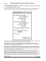
Regulatory Compliance Information
Equipment Label
The Presentation Recorder meets all applicable FCC, CE and ICAN radiation and emission
standards:
Report 3054-1
Electromagnetic Compatibility Test Report
47 CFR Part 2 Subpart J Paragraph 2.906
Report 3054-2
44366 S. Grimmer Blvd. Fremont, CA 94538
Electromagnetic Compatibility Test Report
(510) 490-4307 (510) 490-3441 Fax
ECD 2004/108/EC, LVD 2006/95/EC
(1) Connections between peripherals of this equipment may be made with low voltage nonshielded computer data cables.
(2) Network connections may consist of non-shielded CAT 5 cable.
Warnings
(1) A non-shielded power cord may be used to connect AC power to every component and
peripheral of the system.
FCC NOTICE
This device complies with Part 15 of the FCC Rules. Operation is subject to the following two
conditions: (1) this device may not cause harmful interference, and (2) this device must accept any
interference received, including interference that may cause undesired operation.
FCC NOTICE – INFORMATION FOR THE USER
This equipment has been tested and found to comply with the limits for a Class A digital device,
pursuant to Part 15 of the FCC Rules. These limits are designed to provide reasonable protection
against harmful interference in a residential installation. This equipment generates, uses and can
radiate radio frequency energy and, if not installed and used in accordance with the instructions,
may cause harmful interference to radio communications. However, there is no guarantee that
interference will not occur in a particular installation. If this equipment does cause harmful
interference to radio or television reception, which can be determined by turning the equipment off
and on, the user is encouraged to try to correct the interference by one or more of the following
measures:
(1)Reorient or relocate the receiving antenna.
(2)Increase the separation between the equipment and receiver.
(3)Connect the equipment into an outlet on a circuit different from that to which the receiver is
connected.
(4)Consult the dealer or an experienced radio/TV technician for help.
The user may find the following publication prepared by the Federal Communications Commission
helpful:
“How to Identify and Resolve Radio-TV Interference Problems”
Stock Number 004-000-00345-4, available exclusively from the Superintendent of Documents,
Government Printing Office, Washington, DC 20402 (telephone +1-202-512-1800).
FCC WARNING
Changes or modification not expressly approved by the party responsible for compliance to Part
15 of the FCC Rules could void the user’s authority to operate the equipment.
CE NOTICE – INFORMATION FOR THE USER
NCast Corporation
Revision 2.2
Page 4
NCast Presentation Recorder Reference Manual
This equipment has been tested and found to comply with the limits for a Class A digital device,
pursuant to EN 55022 Rules. These limits are designed to provide reasonable protection against
harmful interference when the equipment is operated in a commercial environment. This
equipment generates, uses, and can radiate radio frequency energy and, if not installed and used
in accordance with the instruction manual, may cause harmful interference to radio
communications. Operation of this equipment in a residential area is likely to cause harmful
interference in which case the user will be required to correct the interference at the expense of
the user.
The user may find the following publication prepared by the Federal Communication Commission
helpful:
“How to Identify and Resolve Radio-TV Interference Problems”
Stock Number 004-000-00345-4, available exclusively from the Superintendent of Documents,
Government Printing Office, Washington, DC 20402 (telephone +1-202-512-1800).
WARNING
Changes or modifications not expressly approved by the party responsible for compliance to EN
55022 Rules could void the user’s authority to operate the equipment.
ICAN Class A Digital Equipment
This Class A digital apparatus meets all requirements of the Canadian Interference-Causing
Equipment Regulations.
Cet appareil numérique de la classe A respecte toutes les exigencies due Réglement sur le
matériel brouilleur du Canada.
NCast Corporation
Revision 2.2
Page 5
NCast Presentation Recorder Reference Manual
1. Introduction
1.1. PURPOSE
The NCast Presentation Recorder Reference Manual is intended for the Audio/Video or Network engineer
who will be tasked with the job of installing and setting up a Presentation Recorder or a system of multiple
Presentation Recorders. This guide is designed to cover topics in depth and to assist in optimizing the
performance of a Presentation Recorder.
1.2. DOCUMENT OVERVIEW
This document is divided into two major sections: the theory of operation and a discussion of parameter
settings.
1.3. PRESENTATION RECORDERS – BASIC MODELS
The Presentation Recorder is a stand-alone network communications appliance which captures RGB (VGA),
Composite, Component, DVI, HDMI, Displayport and optionally 3G-SDI signals from a desktop or laptop,
compresses the image with an industry standard compression algorithm, records the capture to a file,
packetizes and transmits the imagery as an internet media stream, receives a media stream from the
internet, decompresses the imagery, and presents the received information to a viewing audience through
use of a large-screen monitor or via a room projector. Presentation Recorders are able to archive the media
stream in real-time while simultaneously webcasting, allowing for playback by the recipient at a later date.
The following Presentation Recorder models are covered by this documentation:
PR-HD-Basic-R – A rack-mounted unit with streaming and archiving capabilities. The PR-HD-Basic-R
introduces support for up to WUXGA (1920x1200) input resolutions with up to 1080p (1920x1080) capture
resolutions and PiP (Picture In Picture) video and graphics overlay.
PR-HD-Basic-D – A rack-mounted unit with streaming and archiving capabilities. The PR-HD-Basic-D
introduces support for up to WUXGA (1920x1200) input resolutions with up to 1080p (1920x1080) capture
resolutions and PiP (Picture In Picture) video and graphics overlay. This unit has two independent and
identical encoders in a single 1U rack-mount chassis (each encoder and its power supply occupy ½ rack).
The dual-encoding capabilities of this model enables many different applications, for example:
NCast Corporation
Revision 2.2
Page 6
NCast Presentation Recorder Reference Manual
•
Two independent HD encoders – With identical inputs, one encoder may be setup to stream and record a
high-bandwidth, high-resolution stream and the second encoder provides for a reduced resolution,
reduced bandwidth stream.
•
Dual wide-screen delivery – One encoder transmits a hi-def camera stream, and the second transmits a
wide-screen presentation. Telepresence at a budget price!
•
Synchronized Encoders – Two HD wide-screens side by side, giving a dual-HD panorama, or a 3D left-right
image.
•
Two-way Interactive – One encoder is configured for streaming send, and the second is setup for
streaming receive.
•
Fail-Safe System – Each encoder independently transmitting the same material. Should one fail, the
receivers can switch to the other.
•
Hot Standby – A spare unit for critical applications.
PR-HD-Basic-P - A flange-mounted unit with streaming and archiving capabilities. This is a very
small form-factor chassis suitable for mounting on the walls of a podium, on top of or underneath a
podium shelf, in a mobile cart, or on a wall in an equipment room.
PR-HD-Basic-M - A desktop unit with streaming and archiving capabilities. This is a very small
form-factor case suitable for desktop or mobile cart applications.
All PR-HD Series units share a core operating system and base set of features. The mainboard and
connector set is similar for all units. Please review the product spec sheets for further details.
1.4. PRESENTATION RECORDERS – EXTREME MODELS
The Presentation Recorder Extreme has all the features of the Basic model but in addition will record in 1080
definition, stream in 1080 (but simultaneous recording and streaming at this resolution is not allowed). There
is also an HDMI output connector for an all-digital connection to a display monitor.
1.5. PRESENTATION RECORDERS – ULTRA MODELS
The Presentation Recorder Ultra has all the features of the Extreme (except HDMI Out) and in addition
supports 3G-SDI digital input.
NCast Corporation
Revision 2.2
Page 7
NCast Presentation Recorder Reference Manual
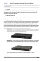
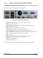
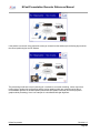
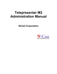
1.6. PRESENTATION RECORDERS – CONNECTOR OPTIONS
The following diagram describes the back-panel connectors available:
Backpanel for PR-HD-Basic-M, PR-HD-Basic-P
•
Serial Control – Wired control from a touch panel, such as Crestron or AMX
•
Ethernet – Connection to the Internet
•
XLR Audio – Balanced XLR input connector and additionally a balanced 0.25” connector
•
VGA – Input from the presenter's PC
•
VGA Loopback – VGA output, usually to the room projector
•
VGA/Component Out – RGBHV or Y-Pb-Pr output to the local display
•
USB – For specifying a static IP connection with a USB drive or saving an archive file
•
Line-In, Line-Out, Mic-In - Unbalanced 3.5 mm. audio connections. Stereo for Line-In, Line-Out
•
HDMI – Video input from cameras or computers, audio not supported
•
DVI-D – Digital input
•
DVI-A – Analog RGBHV input or Y-Pb-Pr component from a camera source
•
Displayport – Input from the Displayport output of a computer
•
SDI – 3G-SDI Serial Digital Input
•
Composite – NTSC or PAL input
Note: Conversion of HDMI or DVI signals to Displayport requires an active (not passive) adapter.
NCast Corporation
Revision 2.2
Page 8
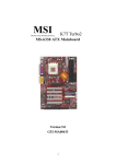
NCast Presentation Recorder Reference Manual
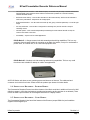
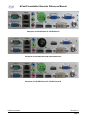
Backpanel for PR-HD-Basic-R, PR-HD-Basic-D
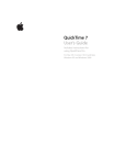
Backpanel for PR-HD-Extreme-M, PR-HD-Extreme-P
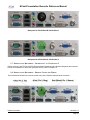
Backpanel for PR-HD-Extreme-R, PR-HD-Extreme-D
NCast Corporation
Revision 2.2
Page 9
NCast Presentation Recorder Reference Manual
Backpanel for PR-HD-Ultra-M, PR-HD-Ultra-P
Backpanel for PR-HD-Ultra-R, PR-HD-Ultra-D
1.7. PRESENTATION RECORDERS – GENERATION 1 VS. GENERATION 2
Earlier versions of the PR-720 and PR-HD Presentation Recorders had a different backpanel and connector
lineup. Documentation on these first generation units is found in Chapter 14.
1.8. PRESENTATION RECORDERS – PHOENIX CONNECTOR WIRING
The Presentation Recorder rack mount models come with a Phoenix balanced audio connector.
NCast Corporation
Revision 2.2
Page 10
NCast Presentation Recorder Reference Manual
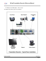
1.9. PRESENTATION RECORDERS – INSTALLATION
The diagram below shows a typical room installation:
NCast Corporation
Revision 2.2
Page 11
NCast Presentation Recorder Reference Manual
2. Quick Start
2.1. STARTUP
2.1.1. A Really Short Start
Here’s a very short description on how to get started:
1. Plug the unit into a network with DHCP, plug in a display to the VGA Out, plug your laptop into the
VGA In, a camera (if you have one) into a video connector and turn on the power.
2. When you see the bootup screen with the IP network address, log into the unit at
http://ipaddress using “admin” as the user and “ncast” as the password.
3. On the Quick Start page select your Channel Layout, your Video Sources, your Audio
Sources and then press Streaming Start.
4. Click on the Streaming View button, press “Launch Quicktime Player in Window” and you’re
done!
2.1.2. Mini Start
This is a short introduction on how to get started with a Presentation Recorder:
1. Plug the unit into a network, plug in a display to the VGA Out, plug your laptop into the VGA In, a
camera (if you have one) into a video connector and turn on the power. If you aren’t using DHCP
and need to enter static IP addresses, edit a “ntwkconf.txt” file onto a USB stick and plug it into a
USB port. See the Configuration → Network tab (7.3.16.) for details on this file.
2. When you see the bootup screen with the IP network address, log into the unit at
http://ipaddress using “admin” as the user and “ncast” as the password.
3. Go to the Configuration → Personal tab and fill in all the information required.
NCast Corporation
Revision 2.2
Page 12
NCast Presentation Recorder Reference Manual
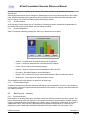
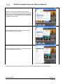
4. On the Quick Start page select the Channel Layout you desire. The icons represent the composition
of the frame which will be recorded and allow for many different combinations of video inputs,
graphics inputs and graphical overlays.
5. The dialog box allows you to choose one of the unit's standard video profiles and permits you to
upload a custom graphical overlay to replace the factory default.
6. Select the Video and Audio sources you have connected to the recorder. The “Main” input is
normally associated with graphics capture and the PIP input usually contains the video camera. You
should see your captured graphics and video on the local display screen. Check your audio levels on
the meter.
7. Press the Streaming Start button to activate the stream.
8. Click on the Streaming View button, press “Launch Quicktime Player in Window”. This dialog box
allows you to connect different media desktop players using multicast protocol. If your network is not
multicast enabled you must be on the same LAN segment as the encoder. Your client player should
launch and you should see your captured graphics and video. For other client players, try clicking on
the “SDP” link.
9. You’re done!
2.1.3. Long Start
Read this whole manual from cover to cover (RTFM). There are hundreds of different configuration
options for a Presentation Recorder, allowing the setup and composition of many different formats,
resolutions, PIP options, layouts, bit-rates, frame-rates, start and stop and scheduling options and the
like. You can automatically upload your archives to a video server. You can tag your archives
automatically with course numbers and notes. You can add your own customized graphic overlays to
the captured graphics and video. Transmission can be automated so that all that is required is to
press the power-on button.
Please feel free to contact NCast Corporation if you have any questions about the use or
configuration of the Presentation Recorder.
NCast Corporation
Revision 2.2
Page 13
NCast Presentation Recorder Reference Manual
2.2. PRESENTATION RECORDER MODES OF OPERATION
The Presentation Recorders have eight major modes of operation:
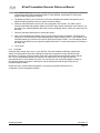
Record to File – The Presentation Recorder only records the file to storage. Once the
Session has ended the file may be automatically uploaded to a video-on-demand server for
later playback by client PCs or mobile devices.
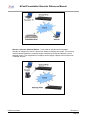
Send a Unicast or Multicast Stream – In this mode of operation one of the Presentation
Recorders is designated as the “Sender” and all of the other units are designated as
“Receivers”. The media streams originate from the Sender and are decoded by one or more
Receivers or desktop client media players. The transmission is strictly one-way, and no
feedback or interactivity is provided for. The one-to-many operation is enabled via use of
multicast connected networks. The unit is able to stream and record simultaneously.
NCast Corporation
Revision 2.2
Page 14
NCast Presentation Recorder Reference Manual
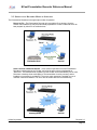
Send a Unicast or Multicast Stream and Record to File – This mode of operation is the
same as “Send a Unicast or Multicast Stream” with the addition of simultaneous recording
an archiving of the captured Session. The archive is first stored internally in local storage and
once the Session is finished the archive may be uploaded to a distribution server or to a locally
attached USB drive.
Send a Stream to an RTMP Server – For live streaming the Presentation Recorder sends an
RTMP protocol stream to a streaming server, CDN or Presentation Server where fanout
occurs and the media is distributed to multiple receiving PC's or mobile devices. The server
MUST be located at a high-bandwidth point on the network to provide for multiple outbound
unicast streams, one for each attached receiver.
Send a Stream to an RTMP Server and Record to File – Supports live streaming using the
RTMP streaming protocol and in addition simultaneously records to create a local archive. See
the diagram and description above.
Send a Stream to an RTSP Server – For live streaming the Presentation Recorder sends an
RTSP protocol stream to a streaming server, CDN or Presentation Server where fanout occurs
and the media is distributed to multiple receiving PC's or mobile devices. The server MUST be
located at a high-bandwidth point on the network to provide for multiple outbound unicast
streams, one for each attached receiver. See diagram above. The RTSP protocol has been
displaced by RTMP for most content distribution networks.
Send a Stream to an RTSP Server and Record to File – Supports live streaming using the
RTSP streaming protocol and in addition simultaneously records to create a local archive. See
the diagram and description above. The RTSP protocol has been displaced by RTMP for most
content distribution networks.
NCast Corporation
Revision 2.2
Page 15
NCast Presentation Recorder Reference Manual
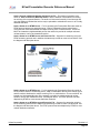
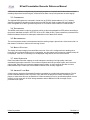
Receive a Unicast or Multicast Stream – In this mode of operation the Presentation
Recorder is configured to receive a stream from another unit acting as a sender. The receiving
unit decodes and renders the composite image created by the sender and displays it on the
attached monitor. This configuration is frequently used to supply a display to an overflow room
or satellite classrom.
NCast Corporation
Revision 2.2
Page 16
NCast Presentation Recorder Reference Manual
3. Theory of Operation
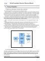
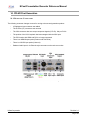
3.1. PRESENTATION RECORDER COMPONENT BLOCK DIAGRAM
The Presentation Recorder consists of these main hardware functions:
Capture Hardware – A custom designed, high-performance module is used to grab and digitize the RGB
or video signals created by the presenter or media source. This module accepts VGA, Y-Pr-Pb, DVI-I, HDMI,
PAL/NTSC composite or PAL/NTSC S-Video connections and converts those signals to YUV digital format.
Two of these inputs may be active simultaneously for generation of a picture-in-picture (PIP) display.
Central CPU – A general-purpose ARM processor is used to compress and decompress audio streams,
to encapsulate and decapsulate outgoing and incoming packets streams, to enable the web interface, serial
interface and telnet interface, and to prepare data for display on the attached monitor. A highly secure opensource operating system underlies and supports all of this functionality.
DSP – A custom DSP is used to compress and decompress YUV video and graphics images to H.264
streams.
Display Output Sub-system – Media streams, which are received and decoded, are presented on the
attached display for viewing. Both RGBHV and component output (Y-Pb-Pr) are supported.
Audio Sub-system – A sound system with stereo input-output capabilities and with support for
microphone and line-level inputs and line-level outputs is used to create the AAC audio streams transmitted
in conjunction with the associated graphics or video imagery. Balanced XLR inputs are also supported
Ethernet Interface – Industry-standard ethernet connectors are used to connect the Presentation
Recorder with the Internet network used for communications.
3.2. CAPTURE MODULE FUNCTION
The capture module selects one of the available six inputs (VGA, DVI-D, DVI-A, HDMI, Composite, S-Video)
and locks onto the signal. The signal is converted into the appropriate digital formats, and each pixel in the
image is stored in a local memory buffer on the module. Any required sizing and re-scaling is done in the
module. At an appropriate time the pixels in module are transferred to the DSP where they are processed
and compressed.
NCast Corporation
Revision 2.2
Page 17
NCast Presentation Recorder Reference Manual
If PIP mode is enabled, two signals may be selected (exceptions: Composite and S-video share one video
decoding chip and are the same signal, VGA and DVI-A share one input chip and are the same signal).
3.3. COMPRESSION
The digitized RGB signals are converted in format from an {R,G,B} representation to {Y,U,V}. Industrystandard compression algorithms implemented in the DSP are then used to reduce the source data to a
more manageable size, and to generate sequences of I-P-B frames found in MPEG-4 media streams.
3.4. TRANSMISSION
The MPEG media stream is split into segments, which are then encapsulated into RTP packets according to
the protocol standards set forth in IETF RFC 3016 or RFC 3984 (H.264). These packets are presented to the
Ethernet hardware interface for subsequent transmission on the attached IP network.
3.5. DECOMPRESSION
The received packet stream is decompressed and the resulting image is placed into a video frame buffer. At
that instant it will become visible to the receiving viewers.
3.6. DISPLAY FUNCTION
The display will output imagery from two different sources. If the unit is configured as the sending unit, a
local copy of the captured image (prior to compression, but after capture and conversion to digital format) will
be displayed. If the unit is a receiving unit, the displayed image will be from the remote sender.
3.7. AUDIO SUBSYSTEM
Each Presentation Recorder supports an audio subsystem consisting of an high-quality codec and
associated input/output connectors. The unit has microphone and line-level input signals, and a line-level
output signal. Each line-level connector supports stereo signals. An XLR connector provides for mono
balanced audio input. Audio input via the HDMI connector is not currently supported.
3.8. ARCHIVE FLASH DISK
A flash memory card in the Presentation Recorder is available for recording transmitted sessions. The file
format is standard MPEG-4 Part 10 (H.264, .mp4), which can be played on a variety of desktop client
players, or these same files can be installed on a video-streaming server for on-demand playback over the
Internet. All unit come with 32 GB of storage standard, and an additional 32 GB of storage may be
purchased as an option.
NCast Corporation
Revision 2.2
Page 18
NCast Presentation Recorder Reference Manual
4. Quick Start Configuration and Setup
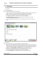
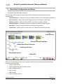
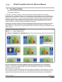
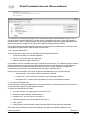
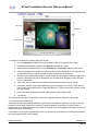
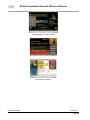
4.1. QUICK START PAGE ORGANIZATION
The Quick Start page is the primary control page for the Presentation Recorder and has six distinct
functional areas:
•
Channel Selection – A Channel is a preset or template containing all layout and startup parameters
•
Source Selection – Input connectors are assigned to the active windows in a video frame
•
Streaming Control – Streaming session activity on a Channel is started or stopped
•
Recording Control – Recording of a session on a Channel is started, paused or stopped
•
Status Bar – A real-time display of session activity and input signal status
•
Control Icons – Special controls to power-off the unit, reboot and several other functions
Control Icons
Channel Presets/Templates
Video/Audio Source Selection
Streaming Controls
Recording Controls
Status Bar
With the Quick Start page the sequence of operations required to activate a streaming/recording session
may be summarized as follow:
1. Select a Channel layout.
2. Select the appropriate video and audio sources.
3. Start a streaming session.
4. Start recording.
5. Stop recording.
6. Stop the streaming session.
NCast Corporation
Revision 2.2
Page 19
NCast Presentation Recorder Reference Manual
4.2. CHANNEL SELECTION
A Channel is a preset containing all the layout and startup parameters needed for a streaming or recording
session. There are seven categories of channel parameters:
•
General – The Channel name and the type of Channel operation desired.
•
Layout – The frame size, aspect ratio, position of the Main and PIP windows and graphical overlays.
•
Quality – The video and audio quality desired and respective bit-rates.
•
Network – The Channel's multicast or unicast addresses.
•
Recording – Archive filenames and other recording parameters.
•
Upload – Disposition of the archive file once the recording has completed.
•
Notifications – Email messages to the administrator of the Channel.
The Quick Start page allows for a limited selection of factory default settings. More comprehensive
modifications to a Channel are done from the Channels tab.
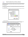
The first dialog box allows selection of a number of standard bit-rates and the upload of custom graphics for
overlay.
Select the lower speeds for material that is mainly graphics and the higher bit-rates for video material.
NCast Corporation
Revision 2.2
Page 20
NCast Presentation Recorder Reference Manual
Graphical overlays are JPEG, GIF or PNG images that may be used to fill in or overlay areas of the frame
being captured. Create a custom graphic in your favorite photo editing program and upload it to the Channel
by selecting “Customize Overlays”. Make sure the dimensions are correct as the Recorder does not do any
scaling of the incoming picture.
When all selections have been made the new Channel will be ready for use and the new layout will appear
on the locally attached monitor.
4.3. SOURCE SELECTION
The selection of which input signal (connector) to use for the Main and the PIP windows is accomplished by
clicking the Video button in the Sources area. This selection may be changed at any time during a recording.
The Swap button will exchange the Main and PIP window settings. The “Main Full” or “PIP Full” will expand
the Main or PIP window to fullscreen.
Similarly, the audio inputs are selected by the audio button. Choices include:
•
Mic – Microphone jack input
•
Line-in – Line jack input
•
XLR – Balanced audio input
•
Input gain – Input level adjustment for the above inputs
•
Output gain – Speaker output level
NCast Corporation
Revision 2.2
Page 21
NCast Presentation Recorder Reference Manual
•
Loopback gain – Controls the feed from the input signal to the output. Watchout for feedback!
The other buttons on this line control these functions:
•
Advanced – Fine adjustment and positioning of the images.
•
Overlays – Shows or hides the graphical or text overlays, allows edit of text overlays.
•
Preview – Creates a static image of the frame being captured.
4.4. STREAMING START/STOP
The Streaming Start button activates a streaming/recording session based on the Channel parameters and
the selected video and audio sources.
Once activated the View button allows reception of the transmitted stream using an appropriate media
player.
NCast Corporation
Revision 2.2
Page 22
NCast Presentation Recorder Reference Manual
4.5. RECORDING
The Recording button starts the recording and archiving of the video/graphics/audio media being presented.
A recording may be Paused and Resumed, and if Stopped and then Started a second file will be created.
The Title button allows entry of metadata for the recorded file (Title, Presenter, Description).
4.6. STATUS BAR
The Status Bar at the bottom of the page creates a real-time report of the activity underway and has
indicators for Streaming and Recording operations and the state of the selected Main and PIP input signals.
Clicking the righthand grey panel collapses the Bar and hides it from view.
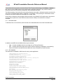
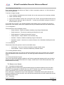
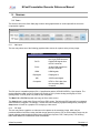
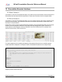
4.7. CONTROL ICONS
The upper righthand corner of the page contains two Control Icons:
NCast Corporation
Revision 2.2
Page 23
NCast Presentation Recorder Reference Manual
Clicking the green arrow expands the slider to reveal an additional set of Icons:
The function of these Icons (left to right) is listed below.
4.7.1.
Reboot
Restarts the unit and reinitializes all processes. This operation may be needed to clear problems after a
power brownout or other unexpected glitch
4.7.2.
Shutdown
Powers down the encoder. It is HIGHLY recommended to power off the equipment with this Icon rather than
simply pulling the plug. All operating parameters will be properly saved and restored.
4.7.3.
Factory Defaults
Restores all Channels and other settings to their factory default. All configuration information will be lost.
Nothing is saved and the reset is irreversible.
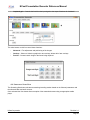
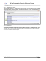
4.7.4.
Export Settings
Once a recorder has been setup and configured, it's highly recommended to export all settings to save the
configuration of the unit for easy restore or repair.
Clicking the Export button will create and download a .zip file with all of the checked information.
4.7.5.
Import Settings
To restore an encoder to a previously configured state, press Import Settings and locate the previously
exported .zip file.
NCast Corporation
Revision 2.2
Page 24
NCast Presentation Recorder Reference Manual
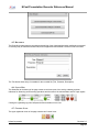
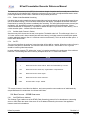
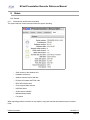
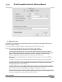
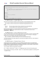
4.7.6.
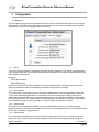
Software Update
NCast regularly releases new software revisions for its encoders with many updated features, new
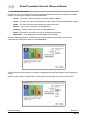
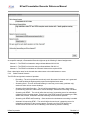
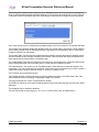
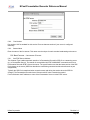
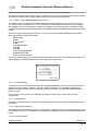
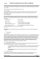
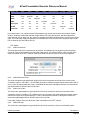
functionality and bug fixes. The Software Update Icon brings up a dialog box with these choices:
•
Network – The update will use the Internet to reach NCast's update server.
•
USB Disk – The encoder is “off net” and a USB thumb drive will supply the required files.
The Network option is normally used to update the encoder, and in the case of a closed or secure network
requiring USB drive files, please contact a customer support person at NCast for assistance in doing a USB
update.
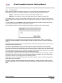
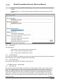
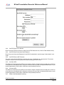
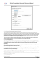
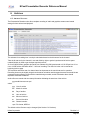
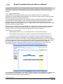
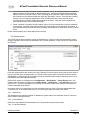
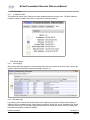
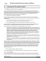
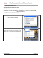
To do an Update, first use the Status tab to determine what release the encoder is currently using. Then
click on the Software Update Control Icon and select “Network”.
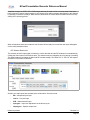
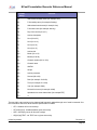
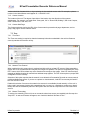
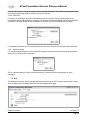
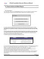
After the Network selection is made, the dialog panel displays the update revision levels available:
If the encoder is not on the latest release, select the desired revision and click “Update”. All necessary
update files will be downloaded over the net and the encoder will reboot once the new firmware has been
installed.
The Support section on NCast's website contains Release Notes outlining what features or fixes have been
implemented in the latest firmware.
The Software Update dialog box lists the current release(s) of software available for this Presentation
Recorder. If no information is listed then there is a problem reaching the update server. The network Update
Tool requires HTTP access to the external Internet to function correctly. If this access is fire-walled or if the
HTTP proxy settings are not correctly employed, then update listings and software updates are not available.
There may also be a problem with the settings for the DNS servers as well.
Once the “Update” button is pressed the Presentation Recorder downloads a list of required files and their
timestamps. Files which are missing or out-of-date are downloaded and installed. The unit will then reboot
and becomes ready for service again with the new software release.
Configuration files are not altered during this process. All Unit, Channel, Source and other settings should
remain intact through this update.
File system verification and new file download may take some time, so allow the unit to reboot on its own
and do not prematurely hit the reset switch as that could damage the filesystem and cause the unit to fail to
restart.
NCast Corporation
Revision 2.2
Page 25
NCast Presentation Recorder Reference Manual
5. The Channel Table
5.1. CHANNEL SETTINGS
A “Channel” is a preset or template, a collection of parameter settings that defines the operating
characteristics for a streaming webcast or a recording session. Just as Channel 2 on your TV defines the
video carrier to be “55.25 MHz.”, Channel 2 on a Presentation Recorder might define the graphics multicast
address to be “239.192.0.1”. There are many parameters associated with a Channel, items like the video
and audio multicast or unicast addresses, port numbers, MTU’s, codecs, bit rates, layouts, overlays and
modes of operation. Think of a Channel as a type of “preset” for all of those parameters. There are 25
Channels allowed, so 25 different presets are available for definition.
By default, the encoder comes with 25 factory-defined Channel layouts for the most commonly used inputs
and compositions. These layouts are not “fixed” permanently, but simply examples of commonly used
arrangements. Any Channel may be completely customized by the customer simply by overriding the factory
default settings.
Once the Channel settings have been established, typically by the administrator of the Presentation
Recorder, or maybe the IT or Network department within an organization, they will not be changed by
ordinary users of the Presentation Recorder. The user is instructed to “Use Channel 2” and no further
detailed instructions are required.
When a Channel is started the Presentation Recorder begins its broadcast or recording Session. All of the
many Channel parameters are transferred to the working Session parameters and the encoding and layout
parameters defined by the Channel become the current encoding mode and layout of the Presentation
NCast Corporation
Revision 2.2
Page 26
NCast Presentation Recorder Reference Manual
Recorder. Any changes or updates to the Channel Table have no effect on the Session until the next
Session start.
Session parameters which may be changed or updated appear on the Quick Start page and on the Custom
page. Windows and Overlays may be altered during a Session, but the initial Frame size and aspect ratio
may not change. The Frame size MUST remain fixed during a Session.
5.1.1.
Channel Initiation
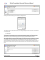
At the left edge of each channel icon is a Start button. Pressing this button activates all the parameters for
the Channel and a new Session based on these settings is started.
5.1.2.
Channel Modification
Setup of a Channel, started by pressing the “Edit” key, is divided into seven parts:
•
General – Channel name, description and the type of operation
•
Layout – Frame size and placement of the Main and PIP windows
•
Profile – Bit-rate, frame-rate and quality settings
•
Network – Setup of multicast and unicast addresses, MTU's and TTL
•
Recording – Recording filename, title and description
•
Upload – FTP or Secure FTP server names and passwords, USB or Presentation Server
•
Notifications – E-mail reports of important Channel events
The paragraphs which follow describe in detail each of these parts.
5.1.3.
Channel Export/Import
A Channel's setup with all required parameters and settings may be exported to a .zip file. This provides for
off-line backup. Use of the Import button allows restoration of the channel, or copying of the parameters from
one channel to another.
5.2.
5.2.1.
EDIT CHANNEL – GENERAL
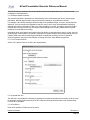
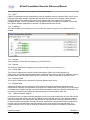
Set Channel Name
Each channel can be assigned a name, and these names can reflect the functional use of the channel. The
factory default settings name the channels in correspondence with their layout properties. Another example
might be “International Sales Team Update” for corporate usage, “Engineering Collaboration” in the case of
departmental usage, “San Francisco” designating some geographical assignments, or “Chemistry 101”
designating course related usage. Additional descriptive text may be added in the “description” field.
NCast Corporation
Revision 2.2
Page 27
NCast Presentation Recorder Reference Manual
As a specific example, a Presentation Recorder might set up the following 3 channel assignments:
Channel 1 – The PR-HD unit transmits using multicast address 239.192.0.0
Channel 2 – The PR-HD unit receives using multicast address 239.192.0.0
Channel 3 – The PR-HD unit initiates an Automatic Unicast to the required CDN.
Enter a descriptive name for the channel that makes sense to the administrators or users.
5.2.2.
Select Channel Scenario
The PR-HD has eight basic modes of operation:
•
Recording – The unit is placed into record-only mode. No stream for internet use is generated.
This mode enables the highest quality capture at the highest frame rates.
•
Streaming Send – The unit will be transmitting in a one-way, one-to-many (multicast only)
session to other units or remote desktops.
•
Streaming Send with Recording – The unit will be transmitting in a one-way, one-to-many
(multicast only) session to other units or remote desktops. Simultaneous recording is enabled.
•
Streaming with RTMP - The unit will utilize the services of a streaming server for rebroadcast
(reflection) of the incoming stream. Through use of the RTMP protocol live streaming to CDN's,
Adobe FMS, Wowza, Evostream and other reflecting servers becomes possible.
•
Streaming with RTMP and Recording – Same as above but simultaneous recording is enabled.
•
Automatic Unicast using RTSP – The unit will utilize the services of a streaming server for
rebroadcast (reflection) of the incoming stream. Through use of the RTSP protocol an
announcement is sent to the server indicating a new streaming session is starting.
NCast Corporation
Revision 2.2
Page 28
NCast Presentation Recorder Reference Manual
5.2.3.
•
Automatic Unicast using RTSP and Recording – Same as above but simultaneous recording is
enabled.
•
Streaming Receive – The unit will be receiving a transmission from some other source on this
network.
Select Media
The media choices:
5.2.4.
◦
Video & Audio – Record with all media, video and sound
◦
Video – Create a video recording with no sound
◦
Audio – Create an audio recording with no video
Auto Start Session
If the “Auto-Start” checkbox is enabled on a Channel, then Session activity for that Channel will automatically
resume when the unit is rebooted or restarted after a power failure.
5.2.5.
Auto Start Recording
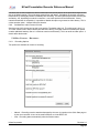
Recording starts and stops when the Session starts and stops.
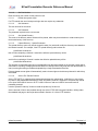
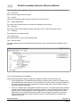
5.3. EDIT CHANNEL – FRAME SIZE
5.3.1.
Set Frame Size
The Frame Size defines the dimensions of the Frame, a surface (capture surface or “the canvas”) which is
the primary imaging surface on which the composite image (Main window + PIP window + Overlays) is
drawn. The resolution and aspect ratio of the transmitted or archived media stream aligns exactly with the
resolution and aspect ratio of the Frame. Consequently, selection of one of the default frame sizes and
aspect ratios, or definition of a custom Frame Size and possibly a custom Aspect Ratio is the first step in
defining the format of the media stream which will be produced by the Presentation Recorder. The Frame
NCast Corporation
Revision 2.2
Page 29
NCast Presentation Recorder Reference Manual
can have any dimension or aspect ratio, with the limitation that the maximum dimensions are 1280 x 720 for
the PR-HD-Basic model.
Once the frame is defined, the next step is the (X,Y) placement and (W,H) sizing of the primary or “Main”
image window/stream. Typically the “Main” stream is sized at “Full-screen” which means that the primary
stream is scaled to the full dimensions of the frame. It is useful to note, however, that the primary stream can
be dimensioned to a smaller size than the full frame size. The unused space might then be reserved for the
secondary image stream (the PIP image, but placed outside the boundaries of the Main image) and possibly
an overlay graphic. A “Main” and “PIP” side-by-side composition would also dictate that the Main image only
occupies one-half of the capture surface area.
5.3.2.
Set Aspect Ratio
The aspect ratio of an image is the visual width divided by the visual height. For most computer systems
“square pixels” are displayed, so the aspect ratio of the image is the pixel width divided by the pixel height. In
video systems, however, often “non-square’ pixels are displayed and the aspect ratio differs from the pixel
width to height ratio. The Frame Size (see 5.3.1. above) only determines the pixel dimensions of an image.
For proper display the aspect ratio must be specified and used to render the final image.
5.4. EDIT CHANNEL – LAYOUT
5.4.1.
PIP
If the “PIP” window is enabled, its (X,Y) placement and (W,H) dimensions are overlaid on the frame.
Typically this might be in the upper-right or lower-right corner of the frame. The PR-HD Series user has the
option of determining if the PIP window obscures any portion of the Main window. It can be placed on top of
or outside of the Main image.
5.4.2.
PIP Border
If this control is selected a small border is drawn around the PIP window.
NCast Corporation
Revision 2.2
Page 30
NCast Presentation Recorder Reference Manual
5.4.3.
Background
A Background graphic or “underlay” may be enabled (and uploaded) to the recorder. It is positioned as the
lowest level graphic in the composition. All other windows and overlays will placed on top of this graphic.
Press the Upload button to upload the background image.
5.4.4.
Graphical Overlays 1-4
Customized images may be added to the media stream being created. These images would typically be
corporate or organizational logos, trademarks or watermarks, copyright statements, media content or date
annotation, or descriptive information on the course or presentation being viewed (speaker, topic, etc.).
There can be up to four different Overlay images per Channel (100 images total). These images must be
created in .jpg, .png, or .gif format. The dimensions of the image must match exactly the space allocated for
the Overlay. They are not scaled during Upload. Transparency in the alpha channel is not implemented.
The information box “Overlay n (Left,Top,Width,Height)” shows where the overlay will appear in the
composition. The (0,0) coordinate is the upper-left corner of the screen. Dimensions are in pixels. Overlay 1
will be obscured by Overlay 2 and then Overlay 3. Overlay 4 is always on top.
The enable/disable setting will cause the image to be included or not included in the composite media
stream being created. More than one image (all four, in fact) may be included if required.
The Channel Table Image Overlays are transferred to the operating Session parameters at Session startup
and thus initialize the image overlays used during the Session. Once a Session has started modifications to
these entries have no effect until the next Session start.
Changes to the Image Overlay(s) in use during a Session may be made from the Quick Start page.
Press the Upload button to upload the Overlays which have been selected.
5.4.5.
Text Overlays 1-4
NCast Corporation
Revision 2.2
Page 31
NCast Presentation Recorder Reference Manual
Text Overlays are windows which contain text to be displayed on the frame. The text can be inserted from
fields on administration web pages (Channel settings), or can be sent via serial RS-232 or Serial Telnet IP
commands. See the Presentation Recorder Serial Interface Specification for details on these commands.
Also, a text overlay may be a calendar time and date stamp to burn in the exact time a recording was done.
Text overlays can implement dynamically displayed text such a news tapes, stock tickers, closed captions,
and for other purposes such as changing the name of the speaker for a presentation due to a last-minute
change of presenters or participants
The Channel Table Text Overlays are transferred to the operating Session parameters at Session startup
and thus initialize the text overlays used during the Session. Once a Session has started modifications to
these entries have no effect until the next Session start.
The enable/disable button will cause the text to be included or not included in the composite media stream
being created. More than one text window (all four, in fact) may be included if required.
The information box “Text overlay n (Left,Top,Width,Height)” shows where the overlay will appear in the
composition. The (0,0) coordinate is the upper-left corner of the screen. Dimensions are in pixels. Overlay 1
will be obscured by Overlay 2 and then Overlay 3. Overlay 4 is always on top.
The Font Size may be specified in pixels.
The Padding specifies a minimum distance (in pixels) between the frame of a window and the text. This
option keeps the text from crowding or adjoining the edge of the window.
Text may be aligned Left, Center or Right within the window.
The RGB color values for the foreground and background may be specified through use of the color picker
dialog box.
Text wrapping may be enabled or disabled.
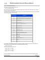
The text may include format strings (e.g. %b, %d, %Y for month, day, year. See table below.).
NCast Corporation
Revision 2.2
Page 32
NCast Presentation Recorder Reference Manual
Format
String
Function
%a
Abbreviated weekday name (for example Sun)
%A
Full weekday name (for example Sunday)
%b
Abbreviated month name (for example Jan)
%B
Full month name (for example January)
%d
Day of the month (01 to 31)
%D
Archive description
%H
Hour (00 to 23)
%I
Hour (01 to 12)
%k
Hour (0 to 23)
%l
Hour (0 to 12)
%L
Archive title
%m
Month (01 to 12)
%M
Minute (00 to 59)
%n
Channel number (001 to 100)
%N
Channel name
%p
AM/PM
%P
am/pm
%R
Archive presenter
%S
Second (00 to 60)
%x
Date (for example 12/31/08)
%X
Time (for example 23:13:48)
%Y
Year (for example 2009)
%z
Numeric time zone (for example -4000)
%Z
Alphabetic time zone abbreviation (for example EDT)
%%
%
The text within a text overlay can be changed and frequently updated through use of serial commands. See
the Presentation Recorder Serial Interface Specification for details.
•
OT0 - disables all four text overlays
•
OT[1|2|3|4],[0|1] - disables/enables given text overlay
•
OS0 - sets empty text on all four text overlays
•
OS[1|2|3|4],TEXT - set TEXT text on given text overlay
NCast Corporation
Revision 2.2
Page 33
NCast Presentation Recorder Reference Manual
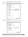
5.5.
EDIT CHANNEL – PROFILE
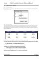
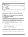
5.5.1.
Set Video Quality
Each channel can be assigned a video quality (bit-rate) level. Use the standard settings or choose Custom
(see the section below).
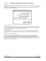
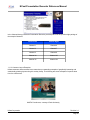
5.5.2.
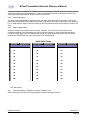
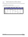
Set Audio Profile
This menu pulldown selects the bandwidth and encoding properties of the audio media stream associated
with the graphics stream. All audio is encoded in the Advanced Audio Coding (AAC) format. Different bitrates and an optional stereo setting provide for a wide selection of audio formats to be associated with the
graphics media stream.
Sample Rate
Channels
Bit Rate
Quality
11 kHz.
Mono
16 kbps.
Phone
22 kHz.
Mono
32 kbps.
FM radio
44 kHz.
Mono
64 kbps.
CD
44 kHz.
Stereo
128 kbps.
Stereo CD
If audio is not to be transmitted or recorded, it may be disabled here as well.
If recording in Mono and using the Line input, make sure that active audio is available on the LEFT channel.
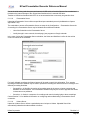
5.6. EDIT CHANNEL – CUSTOMIZED PROFILE SETTINGS
5.6.1.
Format
Select the type of compression encoding desired. The two choices:
•
MPEG-4 (MPEG-4 Part 2 encoding, original MPEG standard)
•
H.264 (MPEG-4 Part 10 encoding, latest industry standard)
Nearly all encoding currently done uses H.264. Choose this as the default.
NCast Corporation
Revision 2.2
Page 34
NCast Presentation Recorder Reference Manual
5.6.2.
Frame-rate
The video frame-rate represents the number of frame (visual image) grabs per second the system will
attempt to achieve. The range of this setting is 1-30 frames per second. For NTSC video encoding a full 30
frames/second is achieved.
At HD720 resolutions, dropping the frame rate to lower values (5 frames/second, for example) allows a
broader range of lower performance PCs to successfully decode the received presentations. It also reduces
the required network bandwidth. At these rates, however, cursor movements look somewhat jerky and
embedded video clips do not play well. One tradeoff might be to send a lower resolution (SVGA, 800x600)
image at a higher frame-rate.
At settings of 10 frames/second cursor movement and drop-down menus look natural, but video still suffers.
At 15 frames/second video playback starts to become acceptable, but high-motion imagery has detectable
artifacts. At the higher rates of 20 frames/second and up both the video and graphics performance look
natural. These high frame-rates deliver smooth animation and video playback that most viewers will find
acceptable.
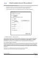
5.6.3.
Bit Rate
The video bit-rate in kilobits-per-second defines the maximum bit-rate that the encoders may utilize in
creating the media stream. For static images the bit-rate may decrease from this peak level.
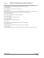
The following table lists the absolute minimum recommended bit-rates for high frame-rates:
NCast Corporation
Revision 2.2
Page 35
NCast Presentation Recorder Reference Manual
Resolution
Minimum Bit-rate
Preferred Bit-rate
QVGA (320x240)
128 kbps
192 kbps
VGA (640x480)
220 kbps
330 kbps
SVGA (800x600)
310 kbps
465 kbps
HD720 (1280x720)
550 kbps
800 kbps
Settings below these values will generate pixelation and other visual artifacts in the received image. Also,
use of the minimum bit-rates will increase end-to-end latency, may reduce the visual clarity of the image and
introduce lip-synch problems. As with any other type of compression system, there is a complex interaction
between bit-rate, frame-rate, image resolution, and end-to-end latency. For HD720 images, settings above
1000 kbps generally produce excellent results. The lowest latency is achieved by setting the bit-rate to the
maximum permitted, which is 5,000 kbps.
Reducing the bit-rate, frame-rate and resolution will allow older PCs operating at lower performance levels to
decode the received imagery without skips and stutters. For the full frame-rate and bit-rate at HD720
resolutions modern PCs in the 2 GHz.+ class are required.
For the lowest bit rate, 128 kbps, a resolution of 640x480 and a frame-rate of 5 frames/second for graphics
or 10 frames/second for video are recommended.
There is no way to define the optimum settings for a given application. It depends on the material being
presented, the expectations for motion smoothness and embedded video performance, the equipment
available to the receiving audience, the maximum network bandwidth available, and other factors. The only
way to determine the optimum settings for a particular installation is to run tests on the material being
presented using the network at hand.
5.6.4.
Key Frame Interval
Changes the number of seconds between key frames (I frames).
Note: This parameter is for advanced users only who fully understand the relationship between this setting
and the impact it might have on other encoder settings and encoder performance. Use extreme caution
when modifying this value.
5.6.5.
Min Quantizer and Max Quantizer
These options set minimum and maximum video quality. The valid range is from 1 (best quality) to 31 (worst
quality). The default range is 2-31 for MPEG-4. For H.264 the range is 0-51 (default is 10-51). Decreasing
min quantizer will increase the maximum possible video quality, and increasing min quantizer will decrease
the maximum possible video quality. Increasing max quantizer will decrease minimum permitted video
quality. Increasing max quantizer too much may cause the encoder to skip frames in order to maintain the
target frame-rate. This is a video encoder option - it doesn't affect the decoder.
Note: These parameters are for advanced users only who fully understand the relationship between these
settings and the impact they might have on other encoder settings and encoder performance. Use extreme
caution when modifying these values.
5.6.6.
Rate Control
•
Constant Bit Rate – The transmitted bit rate is kept equal to or below the bit rate specified.
•
Variable Bit Rate – The transmitted bit rate is allowed to burst as required during scene changes.
5.6.7.
Buffer Size
Sets the Constant Bit Rate buffer size in seconds. This controls how much the bit-rate can vary locally. A
larger buffer size results in higher overall video quality and less frame skips, but increases the video latency.
This is a video encoder option - it doesn't affect the decoder.
NCast Corporation
Revision 2.2
Page 36
NCast Presentation Recorder Reference Manual
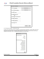
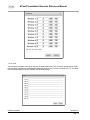
5.7. EDIT CHANNEL – NETWORK
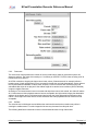
5.7.1.
Set Video Stream Destination - Address
An address entered for Video (the Video or Graphics media stream) will be either a valid multicast address,
or the numeric host IP address of the remote unit if a point-to-point connection is being established.
A full discussion of multicast addressing is beyond the scope of this document, but briefly summarized, there
are three classes of multicast addresses typically used by multicast applications:
Global Addresses – The range of multicast addresses 224.0.1.0-238.255.255.255 are used for global
communications. These addresses are dynamically allocated and not statically reserved. These addresses
are unsuited for static assignment in the Channel Table.
GLOP Addresses – A document, IETF RFC 3180, describes a mechanism for statically assigned multicast
addresses in the address space 233/8 based on a formula that incorporates the Autonomous System (AS)
number in the middle two octets. The AS number is owned by the ISP providing service to the account and
use of a GLOP address must be coordinated with that ISP.
Administratively Scoped Addresses – The multicast address range of 239.0.0.0 to 239.255.255.255 has
been defined to be a range of administratively scoped multicast addresses in IETF RFC 2365. These
addresses may be statically assigned by the administrator of an organization’s network, and there will be no
conflict with other organization’s use of these addresses because border routers on the edge of an
organization’s network enforce policies to stop multicast traffic flow for addresses within this range. Further,
these same border routers can enforce policies so that subsets of these addresses are contained within
NCast Corporation
Revision 2.2
Page 37
NCast Presentation Recorder Reference Manual
administrative boundaries, such as a local LAN, a building, a campus or a region. These are safe addresses
to use in setting up an organization’s multicast network and ideal entries for use in the Channel Table.
Consult with the Network Administrator for the particular address ranges in use on the network hosting the
Presentation Recorder.
All units in one session use the same multicast address. The Video and Audio multicast addresses for a
session can be the same if the Port numbers are different. Units engaged in different sessions should use
different multicast addresses to minimize traffic loading on the network (the multicast routers distribute all
traffic to all points subscribed on a particular multicast address, independent of the port number).
The default settings for a Presentation Recorder use Administratively-Scoped multicast addresses. This
implies that streams created using these addresses will not exit the organization’s network.
If the network is not multicast enabled, point-to-point communications between two Presentation Recorders
is possible by entering the numeric IP address of the remote unit into this field.
5.7.2.
Set Video Stream Destination – Port Number
In addition to a multicast address, each media stream requires a unique port to be assigned. Ports must be
even-numbered (the succeeding odd number is used for control purposes and must be available). Port
numbers range from 1024 to 65,535 and this range is divided into two parts: the Registered Ports are those
from 1024 through 49151 and Dynamic and/or Private Ports are those from 49152 through 65535.
In practice, multicast applications assign port numbers in the range of 5002 and up. The port range 10245000 is typically used by a Unix system to assign ports to applications desiring an automatically generated
port number.
Even if different multicast addresses are being used, it is recommended that different port numbers be used
for the different media streams (graphics, audio and collaboration). On some system implementations, use of
the same port number will cause errors.
For multicast traffic to get through a firewall, the even-odd pair defined in this entry must be opened by the
firewall administrator.
5.7.3.
Set Video Stream Destination - MTU
The Maximum Transmission Unit (MTU) is the maximum length of a packet and is normally set to 1500. For
some special circuits (satellite links, others) the maximum size may need to be adjusted downward to avoid
packet fragmentation, which leads to inefficiencies and possible packet loss.
5.7.4.
Set Audio Stream Destination - Address
An address entered for Audio (the Audio media stream) will be either a valid multicast address, or the
numeric host IP address of the remote unit if a point-to-point connection is being established.
For a discussion of multicast addresses, see the discussion above (Set Video Stream Destination Address).
All units in one session use the same multicast address. The Video and Audio multicast addresses for a
session can be the same if the Port numbers are different. Units engaged in different sessions should use
different multicast addresses to minimize traffic loading on the network (the multicast routers distribute all
traffic to all points subscribed on a particular multicast address, independent of the port number).
If the network is not multicast enabled, point-to-point communications between two Presentation Recorders
is possible by entering the numeric IP address of the remote unit into this field.
5.7.5.
Set Audio Stream Destination - Port
The port number assigned to the audio media stream.
See the discussion above (Set Video Stream Destination – Port Number) for more detailed information on
ports.
5.7.1.
Set Audio Stream Destination – MTU
NCast Corporation
Revision 2.2
Page 38
NCast Presentation Recorder Reference Manual
The Maximum Transmission Unit (MTU) is the maximum length of a packet and is normally set to 1500. For
some special circuits (satellite links, others) the maximum size may need to be adjusted downward to avoid
packet fragmentation, which leads to inefficiencies and possible packet loss.
5.7.2.
Enable Video Bandwidth Smoothing
If enabled, the encoder smooths the stream transmission and sends packets at the prescribed target bit rate
(this is the default setting). This will increase network jitter and latency. If disabled, the encoder uses burst
transmission by sending all packets immediately after encoding. This will significantly decrease network jitter
and latency, but, depending on network connection, it can cause packet loss and bottlenecks. If burst
network transmission is acceptable, it is possible to disable this option to get extra low video latency. This is
a video encoder option - it doesn't affect the decoder.
5.7.3.
Set Max Audio Frames in Packet
Sets how many AAC frames can be sent in one packet. The default value is 8. The valid range is from 1 to
10. Lower values result in lower network jitter and lower latency, but higher network overhead (each packet
contains additional headers). Set to 1 to achieve extra low audio latency. This is an audio encoder option - it
doesn't affect the decoder.
5.7.4.
Set TTL
The time-to-live defines the number of router hops that will be valid for a packet. When the number of hops is
exceeded, the packet is discarded. The minimum value for this field is 1, and a value of 127 or greater
should be used for global transmission.
In some multicast networks TTL defines the “scope” or boundary conditions for containment of the multicast
traffic flow. The following table lists commonly accepted values of TTL used in this manner.
TTL
Scope
0
Restricted to the same host. Won't be output by any interface.
1
Restricted to the same subnet. Won't be forwarded by a router.
<32
Restricted to the same site, organization or department.
<64
Restricted to the same region.
<128
Restricted to the same continent.
<255
Unrestricted in scope. Global.
TTL scopes, however, have fallen into disfavor, and current practice recommends use of administratively
scoped addresses for containment of multicast traffic flows.
5.8. EDIT CHANNEL – RTMP STREAMING
5.8.1.
Set RTMP Server Address
This Channel Type enables use of the RTMP (Flash Streaming) protocol for live broadcast to a streaming
server or CDN. Enter the name of the server or its IP address followed by the name of the application
instance used for this broadcast.
NCast Corporation
Revision 2.2
Page 39
NCast Presentation Recorder Reference Manual
5.8.2.
Port Number
Port number 1935 is standard for this service. Enter an alternate number if your server is configured
differently.
5.8.3.
Stream Name
Enter the name of the live stream. This name must be unique for each encoder broadcasting to the server.
5.9. EDIT CHANNEL – AUTOMATIC UNICAST
5.9.1.
Set RTSP Server Address
This Channel Type enables automatic transfer of a Presentation Recorder’s SDP file to a streaming server
(e.g. a Presentation Server). The transfer is accomplished by RTSP ANNOUNCE commands sent from a
Presentation Recorder RTSP client to the server. The system makes sure that the latest version of the SDP
file is always on the server (SDP files describe the media being streamed and other details such as port
assignments)
Typically the SDP file is transferred when a session starts and during the session when the SDP file
changes. The Presentation Recorder issues "Announced kill" when a session has ended.
For this field enter the IP address or name of the Presentation Server or other RTSP server.
NCast Corporation
Revision 2.2
Page 40
NCast Presentation Recorder Reference Manual
5.9.2.
Set RTSP Server Port Number
Enter the server RTSP port number (usually 554 for RTSP-based servers, 1935 for Flash-based servers).
5.9.3.
Set RTSP Server Username and Password
Enter the account Username/Password for the SDP file authorization (can be empty if authorization is not
used).
5.9.4.
Set RTSP Server SDP Filename
The name under which the SDP file is saved by the server. Should have an .sdp extension. The names
should be unique for each Presentation Recorder accessing the RTSP server.
5.9.5.
Set Video MTU
The Maximum Transmission Unit (MTU) is the maximum length of a packet and is normally set to 1500. For
some special circuits (satellite links, others) the maximum size may need to be adjusted downward to avoid
packet fragmentation, which leads to inefficiencies and possible packet loss.
5.9.6.
Set Audio MTU
The Maximum Transmission Unit (MTU) is the maximum length of a packet and is normally set to 1500. For
some special circuits (satellite links, others) the maximum size may need to be adjusted downward to avoid
packet fragmentation, which leads to inefficiencies and possible packet loss.
5.9.7.
Enable Video Bandwidth Smoothing
NCast Corporation
Revision 2.2
Page 41
NCast Presentation Recorder Reference Manual
If enabled, the encoder smooths the stream transmission and sends packets at the prescribed target bit rate
(this is the default setting). This will increase network jitter and latency. If disabled, the encoder uses burst
transmission by sending all packets immediately after encoding. This will significantly decrease network jitter
and latency, but, depending on network connection, it can cause packet loss and bottlenecks. If burst
network transmission is acceptable, it is possible to disable this option to get extra low video latency. This is
a video encoder option - it doesn't affect the decoder.
5.9.8.
Set Maximum Audio Frames in Packet
Sets how many AAC frames can be sent in one packet. The default value is 8. The valid range is from 1 to
10. Lower values result in lower network jitter and lower latency, but higher network overhead (each packet
contains additional headers). Set to 1 to achieve extra low audio latency. This is an audio encoder option - it
doesn't affect the decoder.
5.10. EDIT CHANNEL – RECORDING
5.10.1. Recording Options
Two options are available for control of recording:
•
Manual – Recording must be started and stopped by the user via controls on the Quick Start page or
by the room controller via one of the serial interfaces or via the REST API.
•
Auto – Recording starts automatically when the Session starts.
NCast Corporation
Revision 2.2
Page 42
NCast Presentation Recorder Reference Manual
5.10.2. Set Recording Filename
The default archived filename is of the form
20071119-143206-001.mp4
which represents the start time of the recording through use of the fields: year, month, day, hours, minutes,
seconds, channel-number, filetype.
This default filename format may be altered to reflect more customized filenames through use of a formatting
string utilizing any of the following codes:
Format String
Function
%a
Abbreviated weekday name (for example Sun)
%b
Abbreviated month name (for example Jan)
%c
4 digit counter
%C
6 digit counter
%d
Day of the month (01 to 31)
%H
Hour (00 to 23)
%I
Hour (01 to 12)
%m
month (01 to 12)
%M
minute (00 to 59)
%n
Channel number (001 to 100)
%p
AM or PM
%P
am or pm
%S
seconds (00 to 61)
%Y
year
%%
%
For example, if a Presentation Recorder user wishes to create a custom filename for the “Accounting 101”
series of lectures, the following filename formatting string might be used:
Acct101-%Y-%m-%d
This will create filenames of the form:
Acct101-2007-11-19.mp4
Acct101-2007-11-21.mp4
Acct101-2007-11-23.mp4
…
Using this formatting notation, the default value of the format string for standard archive filenames is this:
NCast Corporation
Revision 2.2
Page 43
NCast Presentation Recorder Reference Manual
%Y%m%d-%H%M%S-%n
The counter variables start at 0001 or 000001 and go to 9999 or 999999. Only one counter variable is
permitted per filename. The counter’s next value is calculated by scanning existing archives which match the
filename template. The filename with highest counter value is discovered and the counter value found is
incremented by one. If all files are removed the counters will start again from 1.
If a newly created archive filename conflicts with an existing archive, a suffix _n (_1, _2, _3, … ) is added to
the new name to avoid overwriting an existing file.
5.10.3. Set Recording Title
Enter information about the Title of the session being recorded (e.g. class or course number, conference
session title, meeting name, etc.). This information is entered as meta-data about the recorded archive and
will be captured in the .xml data file associated with the archive.
Once a recording has commenced the title information may be updated on the Archives page.
Special text variables %0-%9 may also be entered in this field. See discussion below.
5.10.4. Set Recording Presenter
Enter information about the Presenter of the session being recorded (e.g. class professor or instructor,
conference session speaker, meeting chairperson, etc.). This information is entered as meta-data about the
recorded archive and will be captured in the .xml data file associated with the archive.
Once a recording has commenced the presenter information may be updated on the Archives page.
Special text variables %0-%9 may also be entered in this field. See discussion below.
5.10.5. Set Recording Description
Enter additional descriptive details about the event, the presenter, the topic or background of the recording.
This description field will be used, for example, in automatically creating RSS feeds for the recording once it
has been uploaded to an Presentation Server.
Once a recording has commenced the description information may be updated on the Archives page.
Special text variables %0-%9 may also be entered in this field. See discussion below.
5.10.6. Set Max Recording Time (in minutes)
The Maximum Recording Time specifies when a recording should be unconditionally stopped. This value is
used to prevent “runaway” recordings where the presenter forgets to press the Stop button on the control
panel interface and the unit might be left recording all weekend long. The time value is in minutes and the
default is 10 hours.
5.10.7. Add Hint Tracks to MP4 File?
Streaming servers require some additional information about the contents of a media file to optimize delivery
for remote clients. An additional track, called a hint track, contains this information. If the file is to be used
with a streaming server this option must be checked. If streaming is not required, uncheck to save on file
processing and to reduce the file size.
5.10.8. Optimize MP4 File Layout?
Sometimes a media file is placed on a web server and is played without the assistance of a streaming
server. In such instances the location of the media data required for progressive download needs to be
optimized. Optimization rearranges the audio and video blocks within the file. Optimization does not
significantly affect the size of a file, but adds slightly to the post-Session processing time required. Uncheck
this box if files will not be used in progressive download environments.
5.10.9. Enable Final Cut Compatibility Fix?
Due to certain limitations in Final Cut software (related to frame-rate and variable frame length processing) a
special fix-up operation is required if this file will be imported into a Final Cut editor. Only check this box if
Final Cut import will be needed as it adds to the post-processing time required for the file.
NCast Corporation
Revision 2.2
Page 44
NCast Presentation Recorder Reference Manual
5.10.10. Enable Blackout on Pause and Resume?
This options add a fad in/fade out special effect when the recording is paused.
5.10.11. Special Text Variables
Metadata for the Title/Presenter/Description information is only created after a Channel & Session is started
and recording commences. By default this information is pulled from the Channel template/preset. In most
cases, however, it's desirable to alter this information for each instance of a recording, saving new
Title/Presenter/Description information.
One method to do this is to click on the “Edit” operation on the Archives page, either during or after a
recording.
Another method is to send serial commands (RT, RP, RI) to the unit after recording has started.
To provide for the situation where Title/Presenter/Description information needs to be entered prior to
recording start (say from a scheduling system or data input from an instructor) some special text formatting
variables were created to solve this need.
These formatting variables take the form “%0” to “%9” and the contents of each variable may be sent to the
unit via serial commands (TA, …, TJ).
To use the variable to create a new title, simply enter “%0” in the Title field. The metadata will contain a title
with the contents of the Text “0” variable (TA command). The substitution of the %n format variable with its
underlying text occurs at recording start, so any changes after that time will not be recognized.
The current contents of the Text variables may be viewed on the Configuration-->Custom-->Texts tab.
5.11. EDIT CHANNEL – UPLOAD
The Upload tab provides for automatic upload of archives to a streaming server using File Transfer Protocol
(FTP) or Secure File Transfer Protocol (SFTP), to a locally inserted USB stick, to a Presentation Server or to
a Kaltura Server.
5.11.1.Automatically Upload Recordings?
Automatic upload transfers archives automatically at a scheduled time (or immediately after creating the
archive).
The system marks an archive for automatic upload right after it was created if auto upload is enabled. If auto
upload is disabled archives are not marked and will be not uploaded even when auto upload is later enabled.
Archives marked for automatic upload will not start uploading when a session is active. The automatic
upload mark is preserved after system shutdown or reboot.
Manual upload is available from the Archives page, where a user may choose to upload one archive or all
archives. The selected archive(s) will be marked for manual upload. Manual upload is executed immediately
and can start when a session is active. The system will upload archives marked for manual upload before
archives marked for automatic upload. The manual upload mark is not preserved after system shutdown or
reboot. When the archive is being uploaded to the target destination its transfer progress is shown on
Archives page.
5.11.2.When to Start Uploading?
This menu pulldown schedules automatic upload. It will start immediately after capture or in the selected 1
hour time window (i.e. “After 18:00” means upload after 6:00 p.m., not after an 18 hour delay).
NCast Corporation
Revision 2.2
Page 45
NCast Presentation Recorder Reference Manual
5.11.3.Remove Recording After Upload is Finished?
The recording will be removed after the archive has been transferred to its target location. Actually, the
recording is not removed but is placed into the Trash Can where it remains until accumulated Trash exceeds
the space allocated for it. Trash is carried out at the time a new recording starts. This means that generally a
recording remains available for some time after Upload even though it has been “officially” removed. See
Section 7.10.3. for a discussion on disk space management.
There is an option to “Remove Archives Automatically” which will unconditionally delete recordings when
space is needed. See Section 7.10.6. for information on how to enable this option.
5.11.4.Set Upload Method
There are potentially five different target locations for a finished and ready file: a server using File Transfer
Protocol (FTP), a server using Secure File Transfer Protocol (SFTP), a locally inserted USB stick, transfer to
a Presentation Server using the Capture Agent REST protocol or transfer to a Kaltura server using the
Kaltura API.
There is a Primary Upload choice and a Secondary Upload choice. This allows the Presentation Recorder to
target two different entities for delivery of the file.
For example, the Primary choice could be set to USB and the secondary choice to Presentation Server. This
would allow the Presenter to walk away with the recording on a USB stick and a backup copy is sent to
Presentation Server for processing there.
Another example would be to set the Primary choice to Presentation Server for local content distribution, and
the Secondary choice to FTP the file to a remote CDN service.
The Upload settings are on a per-channel basis, so use of different Channels can facilitate upload to different
places when the archive is ready.
5.11.5.Connection Test
NCast Corporation
Revision 2.2
Page 46
NCast Presentation Recorder Reference Manual
The PR-HD will try to connect to the server and list contents of the upload directory. It uses the current
configuration of all parameters.
5.11.6.Multiple Upload Locations
The Upload information is specified on a Channel basis. Since each Channel has its own unique target
information, different target locations may be accessed by starting or using different Channels.
For example, if the Session starting at 9:00 am needs to be uploaded to Dept. A's server, and the Session
starting at 10:00 am needs to be uploaded to Dept. B's server, this is easily accomplished by specifying
different target sites in the Channel Table. Or if some uploads go to a local, on-campus server and if other
uploads go to a remote CDN server, the Channel Table settings may be used to differentiate the upload
repository for each different recording.
Information about what Channel was used to record an archive is retained with the archive. If later, from the
Archives page, a new upload or re-upload is requested, the system extracts current target settings from the
Channel Table entry and uses that target information to upload the recording. Thus, the “Upload All
Archives” operation may result in the transfer of existing archives to many different target sites.
5.11.7.File Transfer Protocol
Select “File Transfer Protocol” and fill in the required fields.
5.11.8.Upload XML File
The XML file is a metadata file containing everything the recorder knows about the frecording. It can be used
for automatic indexing and processing of the file. Keep this checked unless the XML is not used and does
not need to be uploaded.
5.11.9.Set Server
Enter the IP address or DNS name of the server
NCast Corporation
Revision 2.2
Page 47
NCast Presentation Recorder Reference Manual
5.11.10.
Set Port Number
Enter the server port number for the protocol in use.
5.11.11.
Enable Anonymous Login
For FTP transfer the use of anonymous login does not require any credentials.
5.11.12.
Set Username
The user account for the server.
5.11.13.
Set Password
The password required for the user account
5.11.14.
Set Upload Directory
The name of the directory where archives will be placed, which may be an absolute or relative name (from
the home directory of the account).
5.11.15.
Upload Directory – Special Parameter
The upload directory name may include a special codes (%n) which will modify the directory name based on
the Channel number. For example, if the FTP upload directory path is written as:
pr-hd/Class-%n/archives
then for files completing a Channel 1 session the effective upload directory will be
pr-hd/Class-001/archives
and for files completing a Channel 2 session the effective upload directory will be
pr-hd/Class-002/archives
This provides for automatic placement of uploaded files into directories based on the channel number which
was used for recording. Changing directories based on Channel number may help ease the administration of
many incoming files being recorded and uploaded by a single Presentation Recorder.
Directory based access rights will automatically restrict viewers rights to the directory/channel for which they
are entitled.
5.11.16.
Secure File Transfer Protocol
Secure FTP (SFTP) is supported with password and private key authorization. It will first try to use private
key and if it fails password authorization is used. Only SSH-2 protocol is supported. The private key should
be in Open SSH's SSH-2 format or PuTTY's SSH-2 format or ssh.com's SSH-2 format and can't be
password protected.
Use the “Upload Private Key” button to install the private key for this unit.
Secure retrieval of files is also possible through use of the HTTPS SSL encrypted interface, utilizing either
the standard web page or the scripts documented in Section 12.3 of the HTTP interface.
NCast Corporation
Revision 2.2
Page 48
NCast Presentation Recorder Reference Manual
5.11.17.
Universal Serial Bus Upload
The Presentation Recorders are able to transfer ready archive files to a locally inserted USB drive.
NCast Corporation
Revision 2.2
Page 49
NCast Presentation Recorder Reference Manual
Due to the wide variety (and often poor performance) of USB sticks, all archive files are first recorded and
finished on the internal storage of the unit and then transferred to the external USB drive.
Transfer to USB drives formatted with NTFS is not recommended due to extremely long transfer times.
5.11.18.
Presentation Server
Upload to a Presentation Server utilizes a specialized open-standards protocol (the Matterhorn Capture
Agent REST API).
The credentials to access a Presentation Server are setup in the Configuration → Presentation Server tab.
A recording for a Presentation Server may be initiated via two different methods:
•
Use of the Scheduler on the Presentation Server
•
Locally through in room controls, the web page, java programs or Google calendar
In the case of using the Presentation Server scheduler, the Series and Workflow in effect for the archive
come from entries in the scheduler.
For locally initiated recordings the Channel preset will be used to specify this information. Thus, starting
recordings on different Channels may be used to upload the recording to a different Series or to assign it to a
different processing Workflow.
•
Set workflow – A Workflow is a series of processing steps in the server to ingest, transcode and
distribute the file as desired. The Presentation Recorder will query the server to populate the entries
in these two menu pulldowns.
•
Set series – A Series is a sequence of recordings and controls viewing rights to those recordings.
Consult Section 7.8. for additional information on configuring and troubleshooting a Presentation Server
connection.
5.11.19.
Kaltura Server
Upload to a Kaltura Server utilizes a specialized protocol unique to Kaltura. Uploaded files will be
automatically indexed and made available to viewers.
NCast Corporation
Revision 2.2
Page 50
NCast Presentation Recorder Reference Manual
Enter the following credentials for your server:
•
Set Partner ID – Enter your Partner ID as provided by your network administrator.
•
Set User ID – Enter your User ID as provided by your network administrator.
•
Set User Password – Enter the user password provided by your network administrator.
5.12. EDIT CHANNEL – NOTIFICATIONS
The Presentation Recorder has an extensive system of notifications by e-mail for routine and extraordinary
events related to Channel operation. Events can be informational, like “Archive uploaded” or “Recording
Started Normally”, or they can be error reports such as “Recording Start Failed - Disk Full” or “Archive
Upload Failed”. See Section 7.9. for information on how to setup system-wide error notifications.
5.12.1.Channel N Settings - Notifications
Each Channel provides for entry of an e-mail to be associated with that Channel. Channels are often used in
conjunction with specific presenters or Departments, so the person or Department most closely associated
with the operation of that Channel will be informed of any normal or unusual events. A typical use would be
to inform a presenter or lecturer that the recordings and transcodes have completed and are available on the
VOD server.
See Section 7.9. for detailed information on the entries required for this page.
Click on the “Select Events” button to choose which events to report.
NCast Corporation
Revision 2.2
Page 51
NCast Presentation Recorder Reference Manual
5.12.2.Channel N Settings – Notification Events
A subset of all system-wide events is available for Channel-specific notifications. A system-wide event would
report the start of ANY Session, whereas a Channel-specific event would only report the start of activity on
Channel N. See Section 7.9.11. for additional information on use of this menu.
NCast Corporation
Revision 2.2
Page 52
NCast Presentation Recorder Reference Manual
6. Archives
6.1. ARCHIVE SETTINGS
The Presentation Recorder units allow complete recording of audio and graphics streams onto internal
storage for later retrieval and playback.
The estimate for recording time is a simple calculation based on the bit-rate set for the channel.
Take the bit rate set for the channel in use and divide by eight to get the bytes/second of archive space
needed. Multiply by 3600 to get the bytes required per hour.
So for a 5 Mbps stream (graphics plus audio) we estimate 625,000 bytes/second or 2.25 GB per hour. If we
use a 16 GB archive disk that's about 7.1 hours of recording. The disk size in the unit is noted at the
beginning Archive page.
The resolution and frame-rate of a channel aren't as important as the max bit-rate set for operation.
Recording times may be slightly longer than the above calculation would suggest because the actual bit-rate
generated during operation varies with the material being encoded, and the calculation above should
represent worst-case conditions.
Archive files are named with time-stamp information indicating the start time of the archive:
yyyymmdd-hhmmss-nnn.mp4
where
yyyy Year of archive
mm
Month of archive
dd
Day of archive
hh
Hour of archive
mm
Minute of archive
ss
Second of archive
nnn
Channel number
.mp4 File format, MPEG-4
The default archive filename may be changed (See Section 5.10.2 above).
NCast Corporation
Revision 2.2
Page 53
NCast Presentation Recorder Reference Manual
If the archive time is not correct, check the Date & Time Timezone field settings on the Status → System
tab, check for correct DNS entries on the network page, and finally, determine if any network firewall is
blocking access to the time-servers configured in the Presentation Recorder.
The final processing of an archive file occurs when a Session has ended. If a Session is active an archive file
may be in an incomplete state listed as “Captured” or “Processing”. After pressing the “End Session” button
all archive files will be finished and converted into a “Ready” state.
At the end of a Session the Archive page will show a status of “Unfinished” for files which are in the process
of being hinted, optimized or fixed. When the status becomes “Ready” the archived file is ready for
download.
6.1.1. Download Button
To download one or more archives, select the files to be downloaded and click on the Download button.
In addition to the MP4 file two additional files may be retrieved:
•
XML – Contains metadata about the recording such as Title and Presenter.
•
SRT – Contains a timed text track which may be used for captioning, chaptering or event marking.
Refer to the Serial Command Reference Manual for more information on timed text tracks.
6.1.2. XML Metadata
This information is available in XML format for use by other applications:
<?xml version="1.0" encoding="UTF-8"?>
<archive version="1.0">
<filename>20120926-172747-002.mp4</filename>
<title>NCast Corporate News</title>
<presenter>Sales Staff</presenter>
<description>Weekly summary of Sales activity.</description>
<unit>Presentation Recorder</unit>
<channel>Presentation & HD Video</channel>
<start>2012-09-26 17:27:47</start>
<duration>00:05:57</duration>
<timezone>-0700</timezone>
<width>1280</width>
<height>720</height>
<aspect_width>1280</aspect_width>
<aspect_height>720</aspect_height>
<main_window>320,0,960,720</main_window>
<pip>1</pip>
<pip_window>0,0,320,180</pip_window>
<bit-rate>1064</bit-rate>
<frame-rate>30</frame-rate>
<file_format>mp4</file_format>
<video_format>h264</video_format>
<audio_format>aac</audio_format>
NCast Corporation
Revision 2.2
Page 54
NCast Presentation Recorder Reference Manual
</archive>
The use of XML format allows the content to be encoded in the Unicode (UTF-8) character set.
The <main_window> and <pip_window> tags record the position of these windows at the start of a session.
This information may be useful for downstream video editing processes which wish to extract video or
graphics details from these windows.
The “video_format” types currently supported are “mpeg4” and “h264”. There is currently only one audio
format available, “aac”.
6.1.3. Upload Button
Clicking on this button marks this archive file for immediate upload (via FTP or Secure FTP) to the
configured FTP server (see Section 5.11 for details on (S)FTP server setup). The upload is executed
immediately and can start when a Session is active. Immediate upload may interfere with ongoing Session
streaming, and should be used cautiously or not at all if network bandwidth is not available to support both
streaming and file transfer.
The (S)FTP information is specified on a Channel basis. Since each Channel has its own unique (S)FTP
information, different (S)FTP sites may be accessed by starting or using different Channels.
For example, if the Session starting at 9:00 am needs to be uploaded to Dept. A's server, and the Session
starting at 10:00 am needs to be uploaded to Dept. B's server, this is easily accomplished by specifying
different (S)FTP sites in the Channel Table. Or if some uploads go to a local, on-campus server and if other
uploads go to a remote CDN server, the Channel Table settings may be used to differentiate the upload
repository for each different recording.
Information about what Channel was used to record an archive is retained with the archive. If later, from the
Archives page, a new upload or re-upload is requested, the system extracts current (S)FTP settings from the
Channel Table entry and uses that (S)FTP site information to upload the recording. Thus, the “Upload All
Archives” button may result in the transfer of existing archives to many different (S)FTP sites.
6.1.4. Edit Button
Along with every archive file an associated text file (in XML format) is kept with additional information about
the archive. The Edit button allows entry of “Title”, “Presenter” and “Description” comments into this file.
These entries may be made during the presentation or afterwards.
6.1.5. Remove Button
Places the archive file into the Trash. Files may be recovered from the Trash Can if they have not yet been
automatically deleted by the system during recording operations which require more disk space.
6.1.6. Play Button
The Play button allows an archive to be played directly and immediately on a PC or laptop. No download is
needed.
6.1.7. Unfinished Tab
Files which are not yet ready or are being processed are unfinished. To reduce processing and archive not
ready time, uncheck the “Hints track”, “Optimize MP4” and “Compatibility” options on the recording tab.
6.1.8. Uploads Tab
A list of files uploading or waiting to be uploaded.
6.1.9. Trash Can Tab
Files which have been removed are placed into the system Trash Can. If a file was removed or deleted in
error, opening the Trash Can permits recovery of the file, provided the file was not permanently deleted in
the quest for more recording space. At the start of recording the system empties trashed files until the Trash
Can size threshold is reached (See Section 7.10.4.). If the recording consumes all free space, more archive
files in the Trash Can will be permanently deleted until the disk becomes completely full.
6.1.10. Editing Archive Files
NCast Corporation
Revision 2.2
Page 55
NCast Presentation Recorder Reference Manual
There are several tools which have been used to edit and manipulate MPEG-4 archive files: Quicktime Pro,
Adobe Premiere, Adobe After Effects, Final Cut and Streamclip. There may be, and probably are, other tools
as well, but these are known to work.
The words "video editing" means different things to different people. Common tasks related to manipulating
archive files would include these different activities:
•
Reducing resolution and reducing the frame rate to downsize the file to smaller formats and
smaller bit rates so lower power PCs can successfully play them back.
•
Cleaning up a file by removing unneeded material at the beginning, end or in the middle of a file.
•
Converting archive files to another format (e.g. conversion to RealMedia or WindowsMedia
formats).
•
More complex editing tasks such as adding titles, inserting other video sequences or material
that was not in the original presentation, selectively adding or deleting sequences or scenes
from the original file, rearranging the order of the presentation, adding fancier transitions or
wipes, and technical work such as fixing color balance.
•
Creation of DVDs, VCR tapes, CDs etc. from the original material.
Obviously this could be a long list and the above items are only representative.
The nature of MPEG-4 files (one keyframe - I frame followed by many differential frames - P, B frames) is
hard for a video editor to deal with directly. Any type of more complex edit would require conversion of the
archive files to an I-frame only format (Motion JPEG or DV format, for example) where differential frame
interpolation is no longer required.
Quicktime Pro, an inexpensive add-on to Quicktime player for both MACs and Windows, is suitable for taking
the original files and exporting them to a variety of other formats for further editing or simple playback in the
new format. It is not a video editor and should be used just for straight export of the original files to the new
format.
Adobe Premiere, a well know and very popular video editor from Adobe.
Adobe After Effects (available on PCs and MACs) is a high powered, full-featured video editor, which is very
popular with professional videographers and which can do almost any video editing or rendering task known
to man. It is, however, expensive in both cost and time-to-learn. This package can import the archive files
directly.
Final Cut Express and Final Cut Pro are two popular video editors used with Apple computers.
Squared 5 MPEG Streamclip is an application for editing Presentation Recorder MPEG-4 files, setting In/Out
points, and converting to different formats such as AVI and DV.
The archive files are at the ultra-high-end in terms of resolution and frame rate, and that processing times for
these files are not trivial, with rendering times often being 3 to 7 times real-time (one minute of material may
take three minutes to export, for example).
A high-powered PC is absolutely essential, with something like a 3 GHz. Pentium with 1.5 GB of RAM being
the required hardware. A 1 GHz laptop with 256 MB of memory will not do the job.
Customers should carefully assess what their target audience requirements are, and make recordings in
reduced resolution or reduced frame rates if a lot of down-conversion is contemplated. Keeping everything at
the highest resolution and highest frame rates will be very costly in terms of video-editing post processing.
NCast Corporation
Revision 2.2
Page 56
NCast Presentation Recorder Reference Manual
7. Configuration
7.1. PERSONAL
The Unit Options page gives the Presentation Recorder its unique ID and provides a place to enter systemwide settings. The ID and contact information are transmitted over the Internet to identify this Presentation
Recorder as a member of an ongoing conference session.
7.1.1. Unit ID
The Unit ID uniquely identifies a Presentation Recorder within a conference. The Unit ID can be descriptive
of the location of the unit, or it can reflect the departmental ownership, or any other characteristic that clearly
differentiates it from its peers.
Examples:
PR-HD West Campus
PR-HD Engineering
The Unit ID is written to the XML meta-data file which accompanies each recording, and may be used to
index the recorded file based on information about which unit sourced the recording.
7.1.2. Contact Name
The Contact name is typically the name of the owner or administrator of the unit responsible for being the
source of the generated media stream. It could also be the name of the person in charge of the course
material being webcast. This item is transmitted in real-time over the network as an SDES element in the
RTP protocol (see IETF RFC 1889 for a more detailed description of the Real-Time Protocol). Other SDES
items include the Contact e-mail, Contact phone, Contact location, and Contact web page.
7.1.3. Contact E-mail
The Contact e-mail should be the address of the owner/administrator of the unit or an address where
questions or service requests concerning the unit are sent. The email address should be formatted according
to RFC 822, for example, [email protected].
7.1.4. Contact Phone
The Contact phone should be the number of the owner/administrator of the unit or a number of a service
desk, which a user could contact for help with regards to the media stream being generated. The phone
NCast Corporation
Revision 2.2
Page 57
NCast Presentation Recorder Reference Manual
number should be formatted with a + sign replacing the international access code. For example, a phone
number in the United States would appear as “+1-800-555-1212”.
7.1.5. Contact Location
The location of the unit. The degree of precision of the location is at the discretion of the systems
administrator. For example, one might enter “Sunnyvale, CA” or “Room 23B, Building 5, San Jose Campus,
2050 Tasman Drive, San Jose, CA”.
7.1.6. Contact Web Page
The Contact web page can be the URL of the Contact name’s personal web page, department, service
group, help page or course material outline.
7.2. TIME
7.2.1. Time Zone
The Time zone setting is required so that the timestamp information embedded in the archive filenames
correctly matches the local time-of-day.
7.2.2. Network Time Protocol
When enabled the unit’s system time is synchronized with public or private NTP servers. When stopped the
system time is not synchronized and may drift over longer time periods. This option is controlled by the “Stop
NTP” button, which will terminate any active Session and reconfigure the system. If the NTP client has been
stopped an additional setting for manual time and date setup appears. The NTP client requires a proper DNS
configuration to work correctly.
Selection of this option requires that the network in use allows the Presentation Recorder to access external,
publicly available time servers. If you are on a private or closed network, local NTP servers may be listed in
the “NTP server N” fields.
Disable this selection if access to the network time servers is not available (closed network) or if the unit is
being used in a temporary location with a standalone hub or router (e.g. a tradeshow, conference or demo).
Bootup time will be substantially reduced if the system does not wait for a response from non-existent time
servers.
7.2.3. Manual Time setting
To set the time manually (if the unit is not on a network where time servers are reachable) the first step is to
“Stop NTP”. A new set of buttons will appear, one of which is labelled “Set Date & Time”.
NCast Corporation
Revision 2.2
Page 58
NCast Presentation Recorder Reference Manual
Clicking on this button will bring up the manual time setting window:
There will be some time offset with clock drift, so if running manually the clock time needs to be rechecked
on a periodic basis.
7.3. NETWORK
The Network Configuration page is used to set and report parameters related to the IP address of the unit
and its behavior on an Internet network. The network parameters are normally set using this page, but
alternatively, they may be entered through the use of commonly available USB memory sticks.
When shipped the units are setup with DHCP enabled. The DHCP setting means that any network or router
which provides DHCP services will automatically assign an IP address to the unit. This address is reported
on the display screen during initial bootup. Once that address is noted, the installer may use the web
interface and Network Configuration page to assign the unit to any statically desired IP address, which will
take effect on the next power-on cycle. If this method does not work, use the USB stick method discussed
below.
NCast Corporation
Revision 2.2
Page 59
NCast Presentation Recorder Reference Manual
The following parameters may be configured on the Network page:
7.3.1. DHCP
If DHCP is enabled the unit will automatically receive an IP address from the network’s DHCP server. Some
networks require MAC address registration with the DHCP server before an IP address can be allocated.
The MAC address is on a label on the bottom of the chassis, and is also reported on the Network
Configuration page. If DHCP is disabled, a static IP address must be provided by the installer. Consult with
the IT staff or network management to obtain the IP address allocated for the unit.
7.3.2. IP Address
The static IP address to be used by the unit in numeric form (www.xxx.yyy.zzz). Not required if DHCP is
enabled.
7.3.3. Netmask
The IP netmask in use for this LAN segment (e.g. 255.255.255.0).
7.3.4. Gateway
The numeric IP address of the gateway host on this LAN segment (e.g. www.xxx.yyy.1).
7.3.5. Primary DNS
The numeric IP address of the primary Domain Name Server (DNS) for this LAN segment (e.g.
www.xxx.yyy.10). Domain name servers translate symbolic domain names to numeric IP addresses. Various
processes within the Presentation Recorder may, on occasion, require contact with a valid name server.
7.3.6. Secondary DNS
The numeric IP address of the secondary (or backup) Domain Name Server.
7.3.7. Ethernet Mode
Adjusts the hardware link level settings for the connection between the Presentation Recorder and its
network switch. Normally Auto-negotiation will be sufficient to establish the correct settings, but under special
circumstances the installer may wish to force the Ethernet hardware to assume a different configuration. The
link speed and full/half duplex settings are adjusted through use of the pulldown menu tab.
7.3.8.
USB Stick Network Settings
An alternative way to configure network parameters for the unit is to edit a special text file on a USB memory
stick and to insert that memory stick into any USB slot in the unit during power-on. The operating software
looks for the presence of a USB memory and searches for the presence of a specially named file. If this file
is found, the network parameters are read from the file, installed into unit and used during the network boot
process. Once the unit has booted, the USB memory may be removed and is not required again. The
network settings from the file will be reflected as permanent entries shown on the Network Configuration
page.
NCast Corporation
Revision 2.2
Page 60
NCast Presentation Recorder Reference Manual
The file on the USB stick must be named “ntwkconf.txt” and has the following lines of information:
dhcp=(bool)0
dns_1=(string)8.8.8.8
dns_2=(string)8.8.4.4
ethernet=(string)auto
gateway=(string)192.168.0.1
ipaddress=(string)192.168.0.2
netmask=(string)255.255.255.0
ntp=(bool)1
The “dhcp” keyword accepts two values: 0 which means disabled (no dhcp, use static addresses) or 1 which
means enabled (use dhcp, dynamic addresses). The “dns” values identify the domain name servers. The
“ethernet” keyword accepts these link-level values: auto, 10fd, 10hd, 100fd, 100hd, 1000fd, 1000hd (auto
negotiation, 10, 100, 1000 Mbps, Full or Half Duplex). These values are case sensitive. The other keywords
require numeric IP addresses or netmasks as shown above.
The “ntp” parameter enables or disables network time protocol within the unit. If enabled, the Presentation
Recorder must be on a network where access to public network time servers is available. Disable
(ntp=(bool)0”) this parameter if the unit is on a closed network. Setting this parameter to 0 is useful when the
Presentation Recorder is being used with a simple hub or switch. Long bootup times will be shortened as the
box is no longer searching for network time servers.
This file should be created/edited with any simple ASCII text editor (e.g. Notepad, TextEdit). Do not use an
advanced word-processing editor to alter this file. Each key=value pair must be on a separate line with no
whitespace prior to the key, and no blank lines in the file.
7.3.9. IP Address Display
When the unit boots the On Screen Display (OSD) will show the unit's IP address for about ten seconds.
If the OSD is enabled (on the local loopback screen) the current IP address of the unit will be shown with the
meter continuously, allowing verification of the unit’s address.
7.3.10. HTTP Proxy
Software updates for the Presentation Recorder are achieved through use of HTTP protocol. If the network
being used is firewalled and requires the use of HTTP Proxy services, then this checkbox must be enabled
for proper downloads of new software updates.
7.3.11. Proxy server
The IP address (symbolic or numeric) of the network’s proxy server.
7.3.12. Proxy Port
The proxy server port (e.g. 80).
7.3.13. Proxy User
If the proxy server requires a username and password for access, enter the username.
7.3.14. Proxy Password
NCast Corporation
Revision 2.2
Page 61
NCast Presentation Recorder Reference Manual
If the proxy server requires a username and password for access, enter the password.
All changes to these network settings require a reboot of the unit. Press the “Update & Reboot” button when
all entries are complete and you have double-checked the correctness of these entries.
7.3.15. SNMP – Simple Network Management Protocol
The SNMP protocol is a widely used, industry standard protocol designed to monitor devices of all types
(e.g. routers, servers, switches, PC's, etc.) on a network. Commercial and open-source tools (e.g. Nagios)
are available to provide comprehensive reports on the health of units being monitored. Customers running
multiple PR-HD encoders may benefit from the use of SNMP to track the availability and performance of their
systems.
The PR-HD agent supports protocol versions 1, 2c and 3. The following MIBs (Management Information
Base) are included in this implementation:
SNMPv2-MIB
IF-MIB
RFC1213-MIB
IP-MIB
IP-FORWARD-MIB
TCP-MIB
UDP-MIB
HOST-RESOURCES-MIB
DISMAN-EVENT-MIB
NOTIFICATION-LOG-MIB
For security reasons and to prevent unwanted use and probes of your network it is advised to change all the
default settings in the SNMP configuration window to private, custom values.
7.3.16. Community String
In Versions 1 and 2c of the protocol the community strings identified sets of resources to monitor and some
of these resources could be “read-only” and some could be “read-write”. In most default installations of
SNMP the community string “public” is read-only and returns limited, basic information about the system
being monitored.
Use of Version 1 or 2c protocol is considered to be insecure as clear-text is used and this is easily
compromised.
7.3.17. Security Name
In Version 3 a “Security Name” is similar to a username on other systems. It identifies an authorized user of
the system.
7.3.18. Authentication Password
Authentication is performed by using a user's authentication password to create an authentication key to sign
the message being sent. The signing key is generated from a password that must be at least 8 characters in
length.
7.3.19. Privacy Password
NCast Corporation
Revision 2.2
Page 62
NCast Presentation Recorder Reference Manual
A private key is used to encrypt the data portion the message being sent. The private key is generated from
the privacy password that must be at least 8 characters in length.
7.3.20. Slave Unit
For capture or streaming of two hi-def media streams a pair of encoders may be synchronized using a
master/slave relationship between the encoders. One encoder is designated Master and the other responds
as a Slave. This setup window allows identification of the Slave unit to be controlled by this recorder:
For additional information on use of this facility please refer to the Tech Tip “NCast Dual Stream Recording”.
7.3.21. Remote Logging
For centralized log management and to implement long-term retention of the system logs of the recorders a
Syslog server and port may be specified:
This is a standard feature for Unix/Linux based systems. Contact your server administrator for more
information.
7.4. WEB
The Web tab provides for security settings and selection of the type of HTTP protocol access to the encoder.
Also, the Admin and Coordinator passwords may be changed on this page.
NCast Corporation
Revision 2.2
Page 63
NCast Presentation Recorder Reference Manual
7.4.1. HTTP/HTTPS Access
Normal web access, which is unprotected and insecure, is accomplished through use of the HTTP protocol
typically utilizing port 80. Secure access using HTTPS (the SSL protocol) utilizes port 443. Administration of
the Presentation Recorder in open and insecure networks without the use of HTTPS presents a security risk
and should be avoided.
The Web Control page allows three different options related to Viewer and Administrative access.
•
All HTTP – Utilizes HTTP for Viewer and Administrative access.
•
Viewer HTTP/Admin HTTPS – Utilizes HTTPS for Administrative access
•
All HTTPS – Viewers and Administrators must use HTTPS
The downside of using HTTPS is that SSL Certificates (which usually require an annual fee or license
payment) are required for each Presentation Recorder unit. Non-authoritative certificates may be used, but
Viewers will see ominous warning notices in their browsers about the certificate, asking the user to accept
the validity of the connection. Also, client players such as Quicktime, which need to download .sdp files using
HTTPS protocol, may not function correctly if the certificate is not valid. Consult with your network
administrator about certificate availability for your organization.
Access using HTTPS is straightforward. Simply use the “https” prefix:
https://pr-hd.ncast.com
This will automatically direct the request to port 443, the standard for HTTPS access.
7.4.2. Upload Certificate & Private Key
If an organization has purchased an official SSL Certificate, or has created a non-authoritative one (which
can be done with many different SSL tools) this new certificate may be uploaded and installed on the Web
Control page.
When HTTPS is turned on, the Apache server requires that the certificate be authenticated with a password.
Since this is not possible inside the Presentation Recorder, a private RSA key may be used instead of a
password. If there is not a valid private RSA key available, then Apache will not start. This is used to disable
third parties launching HTTPS with stolen certificates. More information on this topic is at
http://www.apache.org. The pass-phrase should be removed from the private key before upload.
7.4.3. Admin password
The Admin password grants rights to all configuration and setup options for the Presentation Recorder. This
password should be chosen carefully and with security in mind. Avoid use of common names, dictionary
words and the like. A randomly chosen string greater than 8 characters in length is suggested.
7.4.4. Coordinator password
The Coordinator password allows access to the Archive files.
7.4.5. Verify user password
Viewer/user passwords are not currently in use with this release.
7.5. DISPLAY
The Display settings control activity relative to the local display attached to the Presentation Recorder. If
activated this display normally loops back the graphics or video signals selected on the input connectors
(after digitization of the signal). The displayed material shows the final-form composition of what will be
compressed and recorded (except for the audio-meter or OSD, if present). Also, if graphic overlays are being
used, these will appear on the local loopback display.
NCast Corporation
Revision 2.2
Page 64
NCast Presentation Recorder Reference Manual
7.5.1. Mode
Allows a choice of output resolutions: 720 or 1080 (Extreme and Ultra models only).
7.5.2. Colorspace
Early models of the Presentation Recorders only supported Component (Y-Pb-Pr) output connections. Later
models introduced support for RGB output. This control allows selection of the type of output signal
generated on the VGA Output connector.
7.5.3. Loopback
Turns on and off the loopback of locally generated graphics or video input. If a local display and local
loopback is not being used in an installation this setting should be unchecked as that will free up CPU cycles
which are required to generate the loopbacked image.
7.5.4. Loopback Frame-rate
If local loopback has been selected, the CPU will maintain on the local screen a copy of the material which is
being digitized and sent out as a webcast or recorded as an archive. The process of refreshing this screen
consumes CPU cycles, especially if large resolutions and fast frame-rates are involved. Excessive CPU
utilization can negatively impact maximum outbound frame-rates.
This parameter allows the operator to decrease the local loopback refresh loading. The local screen will still
be updated, but at a rate which provides some relief from excessive use. Reduce the setting from the “Full”
value if needed to maximize outbound transmission performance.
Obviously, a very low setting will impair the visual quality (in terms of motion) of the local display.
7.5.5. On Screen Display (OSD)
The On Screen Display (OSD) presents the following information on the locally attached display:
•
Local Audio Levels (Left, Right) – Level of audio to be recorded or streamed
•
Network Audio Levels (Left, Right) – Level of audio being received from a remote source
•
IP address – Current IP address of the recorder
•
Streaming LED – Indicates if the unit is active and in Session
•
Recording LED – Indicates if the unit is recording
When the OSD checkbox is checked, two pairs of audio meters appear on the local loopback display
connected to the Presentation Recorder. The audio meter window is never transmitted over the network nor
recorded as part of the media stream.
The stereo meters on the left show local audio activity originating from the microphone or line-level inputs.
The stereo meters on the right show network activity, that is, strength of the audio derived from the incoming
media stream in full-duplex or collaboration mode.
NCast Corporation
Revision 2.2
Page 65
NCast Presentation Recorder Reference Manual
The local meters are useful to check for proper connectivity and activity of the sound system connected to
the Presentation Recorder. The levels should be checked for proper range, and gains should be changed if
the audio is too hot or soft.
7.5.6. OSD Position
The OSD positioning controls (Top-left, Top-right, Bottom-left, Bottom-right) allow the meter display to be set
in an area of the screen that does not obscure other important windows (like the PIP window, for example).
7.5.7. Configure OSD
The contents of the OSD can be tailored to contain only those elements required to be shown on the screen:
7.6. TELNET SETTINGS
The Telnet tab is used to enable the Telnet Serial Interface to the unit, an interface, which may be used to
send and receive command and control, strings over IP-based networks. See the Serial Interface
Specification Manual for complete information on the serial command interfaces.
NCast Corporation
Revision 2.2
Page 66
NCast Presentation Recorder Reference Manual
If the interface is enabled, secure the interface with a unique and non-dictionary password, and configure the
IP restriction field to only allow the IP address of the controller unit to command the Presentation Recorder.
7.6.1. Telnet
Uncheck access if the serial command interface is not in use.
7.6.2. Password
Choose a password, which has random characters and numbers and is at least 8 characters in length.
Unfortunately, Telnet protocol sends this password in clear-text, so network sniffers may be able to
compromise this entry.
7.6.3. IP Restriction
This limits the valid IP addresses, which may send commands to the Presentation Recorder. Normally this
field should contain a single IP address, which is the IP of the controller in charge of the Presentation
Recorder. Thus, if the password is compromised an attacker will still not gain access to the unit. This field
may contain:
www.xxx.yyy.zzz
A single address
www.xxx.yyy.*
An address range
www.xxx.yyy.0/24
A subset of a network (CIDR notation)
www.xxx.yyy.zzz,sss.ttt.uuu.vvv
A comma-separated list of addresses
www.xxx.yyy.zzz,sss.ttt.uuu.*
A comma-separated list of addresses and ranges
Standard CIDR notation is documented in IETF RFC 4632.
7.6.4. Port
For security reasons the default Telnet port is not utilized. Enter a port number if the factory setting is not
acceptable.
7.7. SCHEDULER
7.7.1. Overview
The PR-HD Series Scheduler is a feature that allows the manager of one or more Presentation Recorders to
schedule these appliances through use of a Google calendar or through use of industry-standard iCalendar
files. The manager can start and stop each Presentation Recorder at a predetermined time, load unique
settings for each individual presentation, send serial control commands to each Presentation Recorder to
provide additional functionality, and specify how and where the Presentation Recorder sends its output, all
without touching the actual Presentation Recorder user interface. All that is required is one or more
Presentation Recorders, each with a connection to the Internet, and access to a Google calendar or an
iCalendar file, no matter where in the world the equipment is located.
7.7.2. Components of the Solution
The Scheduler Implementation uses three components to allow automatic start/stop scheduling of one or
more Presentation Recorders in a network. These components are:
•
An administrative interface based on Google Calendar or other Calendar system using iCalendar
•
A scheduler process which queries the calendar information and activates the Presentation
Recorder.
•
The Presentation Recorder IP serial command interface, which receives commands at the
scheduled times.
7.7.3. Scheduler Overview
The following sections describe how to use a Google Calendar account or an iCalendar file to setup a
schedule for one or more Presentation Recorders and how to use the Scheduler web page.
NCast Corporation
Revision 2.2
Page 67
NCast Presentation Recorder Reference Manual
Complete documentation for the serial command set is in the “Presentation Recorder Serial Interface
Specification”. Please refer to this manual for a more complete description of commands which may be used.
This guide lists a few basic commands which allow the user to start and stop a unit from the Scheduler
interface.
7.7.4. Google Calendar Events
Google Calendar is a web-based interface used to enter calendar events such as meetings and
appointments. It allows multiple personal calendars (e.g. business and home) and allows sharing of public
and private calendars with friends and associates.
One interesting and important aspect of this calendaring system is that Google has defined a standardsbased software API (called “gdata” for many of their services) which allows programmatic access to the
calendars and the events contained within them. The API is implemented in Java and several other
languages, and allows outside programs (e.g. clock widgets, PDA’s, other calendar systems) to access and
create events within a Google calendar.
NCast has taken advantage of this programmable API to implement a scheduling system for Presentation
Recorders where the web-based Google Calendar is the administrative interface for defining session
start/stop times for one or more Presentation Recorders within a customer’s network.
The process works in three steps:
1. An administrator enters one or more scheduled events for a Presentation Recorder
2. The scheduling process queries the calendar at regular intervals and captures these events.
3. Commands sent to the IP Serial Interface of a Presentation Recorder starts and stops the unit.
The calendar interface allows an administrator to setup single or repeating events. The example below
shows a single event scheduled for Tuesday, a Monday-Wednesday-Friday repeating event, and a Mondayto-Friday repeating event. An event is associated with a single Presentation Recorder listed in the “Where”
field. Two events with the same start/stop times on the same day can be directed to two different
Presentation Recorders simply by changing the contents of the “Where” field. The “Description” field
(discussed below) allows customization of the actions executed at scheduled start time.
So to get started, and administrator must establish a Google Calendar account (different from a Google mail
account) and provide a password for this account. Multiple accounts can be established for multiple
Presentation Recorders if that is easier to administer.
NCast Corporation
Revision 2.2
Page 68
NCast Presentation Recorder Reference Manual
Only the primary or default user calendar is processed. The program is not able to deal with secondary
calendars at this time.
7.7.5. Creating Scheduled Events
To create an event click on a time-slot and fill in the following fields:
The "What" field (Title shown above) must contain (anywhere in the field) the letters “PR720” to identify this
as a Presentation Recorder event. Additional words can further describe the nature of this entry (e.g., “Chem
101”, “Weekly Staff”, etc.).
The "When" field (Dates shown above) is used to delimit the start/stop times for the event. The drop-down
menu only shows hour/half-hour entries, but by clicking again on the time field arbitrary times may be
entered. The repeat options allow multiple occurrences of this event. If a stop time of 11:00 am is listed, the
program uses 10:59:59 as the actual stop time. Thus, events may be scheduled back-to-back.
The "Where" field is the DNS name or IP address of the Presentation Recorder to be controlled. Only one
Presentation Recorder may be listed. This allows one calendar to control many different units.
The “Calendar” field must be the primary or default calendar for this account.
The “Description” field is a series of serial IP commands to be issued to the Presentation Recorder at the
time of the Start event (see below). In the example above, “C1” starts the Presentation Recorder session on
Channel 1.
7.7.6. Scheduled Event Commands
The “Description” or content field is a series of serial IP commands to be issued to the Presentation
Recorder at the time the Start event is processed. Each command is terminated with a ";" character. For
example:
C10;
This is the only command needed to start a Presentation Recorder ("Start on Channel 10 with all other
settings unchanged"). A more complicated example:
G3; V1; p1; C8; R1; RP,The CEO; RT,Weekly Performance Review;
where:
NCast Corporation
Revision 2.2
Page 69
NCast Presentation Recorder Reference Manual
G3 Set the Main input to the VGA input connector
V1 Set the PIP input to the Composite video input connector
p1
Turn PIP on
C8 Start session on Channel 8
R1 Turn recording on
RP Set presenter information to "The CEO"
RT Set title information to "Weekly Performance Review"
Commands are case-sensitive and must be written exactly as shown. The commands are processed in the
order given.
The presenter and title information are stored by the Presentation Recorder in an XML file associated with
archived MPEG-4 file. This XML file will normally be uploaded to the content server and can be used to
provide additional details about the content for archiving and indexing.
The "Presentation Recorder Serial Interface Specification" lists all the commands available on the serial IP
interface. Please check that document for additional setup commands that might be issued.
At the end of the event period, the program issues the "End Session" command "PE". No other commands
are sent.
The scheduler program queries the calendar every few minutes. Changes to the schedule may be entered
prior to this query. Once an event has started the event can only be stopped by going directly to the Web interface of the Presentation Recorder and stopping it manually or waiting for the scheduled stop.
The scheduler program does not check for conflicts or overlapping events. If times overlap for a given
Presentation Recorder the results will occur in the order scheduled
7.7.7. iCalendar Overview
There are many different calendar applications in use, both PC based and Web based. NCast provides a
facility to utilize these other calendar applications to generate schedules through a file interchange standard
known as “iCalendar”.
Another situation where use of an iCalendar file would be needed is when immediate access to Google
Calendar is not available. For example, if Presentation Recorders are being utilized to record a conference
on a closed network at a hotel without Internet access, the scheduler file can be created for all tracks of the
conference and used to run all machines during the event.
7.7.8. The iCalendar Standard
iCalendar is the name for an Internet industry standard from the Internet Engineering Task Force (IETF):
•
RFC 2445: Internet Calendaring and Scheduling Core Object
•
RFC 2446: iCalendar Transport-Independent Interoperability
These standards specify the format and contents of a file (usually a “.ics” file) which contains text strings
describing calendar events. The sample below is a small portion of a typical iCalendar file:
BEGIN:VCALENDAR
PRODID:-//Google Inc//Google Calendar 70.9054//EN
VERSION:2.0
CALSCALE:GREGORIAN
METHOD:PUBLISH
X-WR-CALNAME:NCast Corporation
X-WR-TIMEZONE:America/Los_Angeles
BEGIN:VTIMEZONE
TZID:America/Los_Angeles
X-LIC-LOCATION:America/Los_Angeles
BEGIN:STANDARD
TZOFFSETFROM:-0700
TZOFFSETTO:-0800
NCast Corporation
Revision 2.2
Page 70
NCast Presentation Recorder Reference Manual
TZNAME:PST
DTSTART:19701025T020000
RRULE:FREQ=YEARLY;BYMONTH=10;BYDAY=-1SU
END:STANDARD
The iCalendar file interchange standards are not associated with the popular Macintosh program “iCal” or
any other specific calendar application. The files provide a standard way to export, import and exchange
calendar events, ToDo’s, meeting invitations and blog entries between different computer applications, and
indeed, many different programs now support this standard (including Google Calendar).
The NCast Scheduler can read standard iCalendar (.ics) files containing scheduled events, and can control
Presentation Recorders based on the contents of these events.
7.7.9. Using an iCalendar File
There are three basic steps to use an iCalendar file with the NCast Scheduler:
1. Create the schedule in a calendar application
2. Export a “.ics” file with the event information
3. Start the scheduler program with this file.
It is possible to use both iCalendar and Google Calendar at the same time. The scheduler program reads the
file first and extracts up to one month’s worth of events from the file, then checks for a Google Calendar
account and utilizes any additional event information coming from Google Calendar. Overlapping or
conflicting event information is not checked for and could cause scheduling errors.
Entering the event information is similar to the process described above using Google Calendar:
•
Summary field – must contain “PR720” somewhere in the field
•
Location field – must contain the IP address of the Presentation Recorder
•
Description field – contains serial commands to be sent to a Presentation Recorder
7.7.10.Importing iCalendar Files
An alternate way of utilizing iCalendar files is to first import them into a Google Calendar account, and then
use the Scheduler program only with Google Calendar.
To import an iCalendar file into Google:
1. Go to the “Settings” link (upper right corner) and click on it.
2. Select the “Import Calendar” tab and click on it.
3. Browse for the “.ics” file on the PC and select it.
4. Choose the default or primary calendar for the account.
5. Click “Import”
6. Verify that the events have been properly imported and that all required fields are present.
This facility allows Presentation Recorder scheduling from almost any calendar application in use.
NCast Corporation
Revision 2.2
Page 71
NCast Presentation Recorder Reference Manual
7.7.11.Exporting iCalendar Files
Each calendar application should have an “Export” or “Save” command to create an “.ics” file for backup or
use by other applications.
To do this in Google Calendar:
1. In the “Calendars” sidebar/block on the left side, click on the menu pop-up for the primary calendar.
2. Select “Calendar settings”.
3. In the “Private Address:” details, click on the green “ICAL” button. A pop-up window should come up.
4. Right click on the “basic.ics” and do a “Save as …” function in your browser, saving the .ics file to a
known location in your PC.
If you simply click on the link, your calendar application will probably come up, and that is not the way to
save the file. It will, however, allow you to import the file into your calendar and look at the contents locally.
7.7.12.Configuration
These parameters control scheduler process:
•
Google calendar – Enables or disables scheduling using Google Calendar data.
•
Google username – The account containing the calendar to be used.
•
Google password – Password for the above account
•
Google keyword – Unique identifier for the calendar entry
•
iCalendar – Enables or disables scheduling using an iCalendar file.
•
iCalendar to upload – Use this item to enter the filename of the iCalendar scheduling file which
will be used.
7.7.13.View Buttons
These buttons allows the operator to check on scheduled events:
•
View Google – Check on activities scheduled by Google calendar entries.
•
View iCalendar – Check on activities scheduled by iCalendar entries.
7.7.14.Viewing Scheduler Activity
The Logs page (See Section 8.3.) permits viewing the scheduler activity logs for possible error messages,
reports on scheduled events and other actions. The Serial log contains information on serial command
activity.
7.7.15.External Scheduler Program
There is an external utility program available (in the Python programming language) which may be used to
schedule multiple Presentation Recorders from a single, central location. Check the download area of the
NCast website for this utility.
7.8. PRESENTATION SERVER
7.8.1. Credentials and Configuration
The upload process to PS fits into the Upload method used by the Channel architecture of the encoder.
Upload to PS is conceptually no different than, say, and FTP upload to any other content management
system. Special REST API's have been implemented to execute this upload.
So, the first step in configuration is to go to the Configuration-->Presentation Server panel and enter the
required credentials to access the server. Once this has been entered and the function enabled the encoder
will register with the server.
7.8.2. Scheduling
NCast Corporation
Revision 2.2
Page 72
NCast Presentation Recorder Reference Manual
If the Presentation Server scheduler will not be used, uncheck this box to save unneeded network activity.
7.8.3. Server/Port
Enter the server address and access port.
7.8.4. Use SSL
Check if communications with the server is required to use SSL protocol.
7.8.5. Capture Agent Name
The unique name for this encoder to be used when registering with the server.
7.8.6. Username
The account name used by Capture Agents to log into the server. Usually the system account.
7.8.7. Password
The password for the system account.
7.8.8. Media Flavor
The default tag/flavor to use for the uploaded media.
7.8.9. Serial command
This entry specifies the serial command which will be used to start a Channel when a scheduled event is
activated.
7.8.10.Troubleshooting the PS Installation
Use the following checklist if there are problems in getting the encoder to work with the server:
1. On the Configuration-->Presentation Server tab double check that the correct server address, port
and credentials have been entered. Try the Connection Test and/or view the upcoming Schedule. At
this point the encoder should be registering as a Capture Agent and its status should be visible on
the server's Capture Agent page.
2. There is no Capture Agent configuration required on the server. The Capture Agent simply registers
with the server and tries to pull down its upcoming schedule. If there is no status visible, make sure
that the encoder's DNS settings are correct and that there is no firewall blocking the ports (often
8080) used to communicate with the server. Make sure each Capture Agent has its own unique
name. Getting the encoder to register with the server is a critical step and must completed for
anything else to work.
NCast Corporation
Revision 2.2
Page 73
NCast Presentation Recorder Reference Manual
3. If the status shows that the Capture Agent is registered, next try to manually start/stop a recording.
Modify a Channel for PS Upload as described previously. Select the desired Workflow and Series.
Make sure that the Channel is set for “Auto” recording on the Channels-->Edit-->General tab. Start
the Channel from the Channels page and check that “Recording” is active. Then Stop the recording
Session. Go to the Archives page and see if the recording has been created. As soon as the
recording becomes “Ready” the file should upload to the server. Verify that a new Workflow has
been launched on the server's Workflows page.
4. Finally, schedule a recording for future capture. Allow 10-15 minutes lead time for all the schedules
to get synced. Verify that the encoder is seeing the event using the “View Schedule” test button. At
the scheduled time the encoder should be recording. Upload should work the same way as a manual
event.
Please contact NCast if any of these steps are not working.
7.9. NOTIFICATIONS
The PR-HD Series has an extensive system of notifications by e-mail for routine and extraordinary events
during its operation. Events can be informational, like “Archive uploaded”, or they can be error reports such
as “Disk full”.
Event are categorized by their severity level (Info, Warning, Error and Critical), and by their specific action or
type (e.g. Session start, Recording start, etc.). Events can be system-wide (e-mails are sent to the system
administrator) or Channel specific (a subset of events is associated with a single Channel and sent to an email address associated with that Channel).
System-wide events are configured in the Configuration → Notifications → Select Events menu, and
Channel related events are configured in the Edit Channel → Notifications → Select Events menu (see
Section 5.12.). The rules controlling event reporting are the same in both cases, except for the System or
Channel orientation of the activity.
In summary, there is a comprehensive e-mail notification system in place to inform the administrator that
“The disk is full!” or the Channel owner that “Your recording is ready” and many other notices.
7.9.1. Notifications
This dropdown menu selection enables or disables the system-wide e-mail notification service. It does not
affect Channel notification activity.
7.9.2. E-mail Address
Enter the e-mail address of the administrator to be informed about system-wide events.
7.9.3. E-mail from Address
NCast Corporation
Revision 2.2
Page 74
NCast Presentation Recorder Reference Manual
Enter the e-mail address denoting the source of this email (this unit). Something like [email protected] would instantly identify the source of the e-mail.
7.9.4. SMTP Server
Enter the DNS address or IP number of your mail server.
7.9.5. SMTP Port
Enter the port number needed to contact your SMTP (outbound) server. Normally port 25, the port number
might be non-standard due to firewall rules, ISP restrictions or other requirements.
7.9.6. SMTP Authentication
Check this box if your SMTP server requires authentication.
7.9.7. SMTP Username
The username required for authenticated e-mails.
7.9.8. SMTP Password
The password required for authenticated e-mails.
7.9.9. SSL/TLS
Check this box if your SMTP server utilizes secure SSL or TLS connections.
7.9.10.Connection Test
Clicking this button will send a test message to the account listed on this page.
7.9.11.Select Events
This button brings up a checkbox menu which allows selection of notifications by severity level or by type.
NCast Corporation
Revision 2.2
Page 75
NCast Presentation Recorder Reference Manual
There are two methods by which to choose a notification to be reported:
•
Select by event type – Any event which is assigned the selected severity level is reported. Selecting
“Info” will report Info level events, but not others. You must also select “Critical” and “Error” to be
informed about events classified as Critical and Error.
•
Select by event name – Any activity identified by the given name is reported. It does not matter if the
“type” box is checked or not, the report is issued.
So a typical strategy for using this selection page is as follows:
First, select the severity level desired for reporting. Typically this would be “Critical” and “Error” unless there
is an interest in the more frequent and less interesting “Warning” and “Info” messages.
Next, select particular events of interest to be reported. Perhaps “Session start” and “Recording start” are
required. The net result is that all “Critical” and “Error” messages will be generated, and “Info” level
messages about “Session start” and “Recording start” will be sent as well.
7.10. CUSTOM
7.10.1.Windows
The Custom Windows page allows users of the Presentation Recorder to define unique dimensions for the
Main and PIP windows to be referenced by serial commands. This allows a serial command to easily change
the position ans size of a window.
NCast Corporation
Revision 2.2
Page 76
NCast Presentation Recorder Reference Manual
7.10.2.Texts
Text formatting variables (%0 through %9) may be used to define the Title, Presenter and Description fields.
Normally these variables are initialized and changed through the use of serial commands (TA-TJ). This table
lists and allows editing of the ten available text formatting strings.
NCast Corporation
Revision 2.2
Page 77
NCast Presentation Recorder Reference Manual
7.10.3.Disk
There are four specialized settings that apply to diskspace management. These allow the user to fine tune
management of the free archive space:
7.10.4.Trash Can Size
The Trash Can size specifies how much of the disk may be used to store trashed (deleted or removed) files.
If the trashed files exceed the spec then the oldest ones are removed until the trash limit is reached. Trash
cleanup is normally done just prior to the start of a new recording.
7.10.5.Disk Threshold
These settings are for Event messages. They may trigger mail to the system administrator that the disk
needs cleanup. They do not directly contribute to file cleanup or removal. They are simply warning trigger
levels.
7.10.6.Remove Archives Automatically
The Remove Archives Automatically checkbox will cause unconditional and unquestioned removal of
archives as space is needed. This policy should be used with caution and assumes that it's better to throw
away old recordings (without asking or knowledge of the administrator) than to stop a new recording
because of lack of available disk space. A new large or runaway recording could delete the entire contents of
the Archive disk with this item checked.
NCast Corporation
Revision 2.2
Page 78
NCast Presentation Recorder Reference Manual
8. Status
8.1. SYSTEM
8.1.1.
Serial Number and Revision Information
The System tab lists current information about this system including:
•
Serial number of the hardware unit
•
Hardware architecture
•
Software release revision and date
•
Revision of firmware and FPGA code
•
REST API interface level
•
Current system date and time
•
USB Disk Status
•
Archive space available
•
Mainboard temperature
•
Fan speed
When reporting problems to NCast it is very helpful to copy and send this information as part of a trouble
ticket.
NCast Corporation
Revision 2.2
Page 79
NCast Presentation Recorder Reference Manual
8.2. NETWORK
8.2.1.
IP Address Details
The Network tab reports the IP address and other related parameters currently in use. The MAC address is
frequently needed to register this device on corporate or university networks.
8.3. EVENT LOGS
8.3.1.
Event logging
Many events during the operation of the Presentation Recorder are recorded in the Event Logs. These Logs
are part of the Event Notification System discussed in Section 7.9.
8.3.2. Download Logs
Log reporting is an important tool which NCast uses to diagnose any problems, whether they hardware or
software, bugs or operational issues. When reporting a problem, please click on the “Download Logs” button
which will create a .zip file of recently logged activity. Make a note of the time of the incident (if known) and
forward this information to NCast for analysis.
NCast Corporation
Revision 2.2
Page 80
NCast Presentation Recorder Reference Manual
8.4. SERIAL LOGS
8.4.1.
Serial Command Logging
Serial command activity can be initiated from the RS-232 connector or the Telnet interface. Serial commands
are also used with the Scheduler interface. This screen allows inspection of recent activity for the Serial link.
8.4.2. Download Logs
Log reporting is an important tool which NCast uses to diagnose any problems, whether they hardware or
software, bugs or operational issues. When reporting a problem, please click on the “Download Logs” button
which will create a .zip file of recently logged activity. Make a note of the time of the incident (if known) and
forward this information to NCast for analysis.
NCast Corporation
Revision 2.2
Page 81
NCast Presentation Recorder Reference Manual
9. Sources
9.1. VIDEO
The Sources line on the Quick Start page controls what graphics/video or audio inputs will be sent to the
compression engines.
9.1.1.
Main input
The user may select one of the following graphics/video sources for capture as the primary image:
Graphics/Video
Input
VGA
RGB analog signals from
the 15-pin VGA connector
DVI-D
Digital RGB signals from
the DVI connector
DVI-A
Analog RGB signals from
the DVI connector
HDMI
HDMI signals
Displayport
Displayport In
SDI
Composite
3G-SDI serial digital
NTSC or PAL video from
the composite (BNC)
connector
The DVI input is compatible with the DVI 1.0 specification and the VESA DCC/EDID 1.3 specification. The
required interface cable is a DVI-D (Single Link Digital) or DVI-I (Combo Analog and Digital) or DVI-A
(Analog RGB). A DVI-D (Dual Link) cable is also acceptable.
The Main Full or PIP Full expands the image to fill the entire screen.
The Swap button is used during Picture-in-Picture (PIP) setups. The Main and PIP inputs will be exchanged
when the button is toggled. For example, if a video PIP was overlaying a graphics background, pressing the
Swap button will result in a graphics PIP overlaying a video scene.
9.1.2.
PIP Input
The user may select a graphics or video source for capture as the secondary image, which may be
positioned inside of and thus overlay the Main image (picture-in-picture, PIP) or the secondary image may be
placed adjacent to and outside the Main image (picture-out-of-picture, POP, side-by-side). The following
table shows Main/PIP combinations which are available:
NCast Corporation
Revision 2.2
Page 82
NCast Presentation Recorder Reference Manual
MAIN \\ PIP
VGA
DVI-A
DVI-D
HDMI
DISPLAYPORT
3G-SDI
COMPOSITE
VGA
Duplicate
Comp
Yes
Yes
Yes
Yes
Yes
DVI-A
Comp
Duplicate
N/A
Yes
Yes
Yes
Yes
DVI-D
Yes
N/A
Duplicate
No
Yes
Yes
Yes
HDMI
Yes
Yes
No
Duplicate
Yes
Yes
Yes
Displayport
Yes
Yes
Yes
Yes
Duplicate
Yes
Yes
3G-SDI
Yes
Yes
Yes
Yes
Yes
Duplicate
Yes
Composite
Yes
Yes
Yes
Yes
Yes
Yes
Duplicate
In the above table, “Yes” implies that the PIP arrangement is normal and could be used during a capture
session. “Duplicate” implies that the Main image and the PIP image are identical, and this arrangement
would normally not be used. The “No” entries are present because the HDMI and DVI-D conflict on the digital
input. The Comp entry allows simultaneous use of RGB on the VGA connector with component input on the
DVI-A connector (but not RGB on DVI-A).
9.2. AUDIO
9.2.1.
Audio Connections
There are three audio input connectors on the chassis, XLR (balanced), line (high-level) and microphone
(low-level). This control selects the primary audio input source. If recording in Mono, make sure the active
audio is available on the LEFT channel. Audio over HDMI or audio over SDI is not currently supported.
9.2.2.
Audio Microphone Gain
The audio microphone gain adjusts the signal level from the microphone to the input of the audio codec.
A reference signal of –40.0 dBu ( 7.75 mV RMS) will produce maximum sample values when the Mic Gain is
set to a value of approximately 90. If this is considered the internal 0.0 dB signal reference, the chart shows
gain adjustments for different values of Mic Gain.
9.2.3.
Audio Line-In Gain
The audio line-in gain adjusts the signal level from the line-in connector to the input of the audio codec.
A reference signal of 0.0 dBu (0.775 V RMS) on the line-in connector will produce maximum sample values
with the line-in gain set to approximately 21. If this is considered the internal 0.0 dB signal reference, the
chart shows gain adjustments for different values of Line-in Gain.
If recording in Mono, make sure the active audio is available on the LEFT channel.
9.2.4.
Audio XLR Gain
The audio line-in gain adjusts the signal level from the line-in connector to the input of the audio codec.
NCast Corporation
Revision 2.2
Page 83
NCast Presentation Recorder Reference Manual
A reference signal of 0.0 dBu (0.775 V RMS) on the line-in connector will produce maximum sample values
with the line-in gain set to approximately 21. If this is considered the internal 0.0 dB signal reference, the
chart shows gain adjustments for different values of Line-in Gain.
9.2.5.
Audio Output Gain
The audio output gain adjusts the signal level from the audio codec to the line-out connector. This signal
powers the local speakers (after suitable amplification) and delivers the audio media stream to the audience.
For a 0.0 dB reference signal (maximum sample values) the measured output levels in dBu are shown in the
chart.
9.2.6.
Audio Loopback Gain
Allows input audio to be looped back to the output connector. The normal use of this loopback is for
confidence checking of the input audio on a control monitor or speaker. If input microphones are able to
pickup this output signal, serious feedback loops (whine) will result. Setting this value to non-zero where
speakers and microphones are in the same space is not recommended.
Audio Gain Charts
Mic Gain
Amplification
Line-in Gain
Amplification
Output Gain Output Level
0
0
0
10
10
10
20
20
20
30
30
30
40
40
40
50
50
50
60
60
60
70
70
70
80
80
80
90
90
90
100
100
100
9.3. ADVANCED
9.3.1.
Advanced Settings - Brightness, Contrast, Saturation, Hue
These values allow fine tuning of image brightness, contrast, saturation, and hue.
NCast Corporation
Revision 2.2
Page 84
NCast Presentation Recorder Reference Manual
The following table shows the allowable ranges of adjustment:
Control
Range
Brightness
0-100
Contrast
0-100
Saturation
0-100
Hue
0-100
For each Control there are four adjustments for the five different inputs: VGA, DVI-D, HDMI, Composite and
Displayport.
9.3.2.
Advanced Settings – Fine Position
These buttons control fine positioning of the Graphics image (VGA, DVI-A input connector only). The image
will move a few pixels to the left, right, up or down when these buttons are activated. The center button
attempts to center the image properly on the screen.
9.3.3.
Layout
Some layouts are a mix of 16:9 and 4:3 windows. If the Swap button is pressed with a mix of two different
window aspect ratios there will be distortion. When there is a change of speakers with a change of
computers, there may be a change of aspect ratios for a given connector. Keeping all these possible
variations captured correctly is a real problem.
This panel allows fine tuning on how input signals are mapped to their respective windows. Techniques of
full-screen stretching, letter-boxing and pillar-boxing may be used.
9.3.4.
AV Sync
Viewers notice and are very sensitive to problems with AV Sync (Lip sync). It's a complex problem to solve
and sometimes the audio and video are not in sync when they arrive at the encoder (due to DSP processing
delays for in-room equipment or other causes).
NCast Corporation
Revision 2.2
Page 85
NCast Presentation Recorder Reference Manual
This control panel allows +/- timing adjustment for audio, allowing fine control over aligning video and audio
sync to match perfectly.
The range of adjustment is +/- 500 milliseconds.
9.4. OVERLAYS
9.4.1.
Image Overlays
Enables or disables display of uploaded graphical overlays 1-4. Overlay graphics are initialized from the
Channel Table presets.
The settings of these buttons are OVERWRITTEN during Session start.
9.4.2.
Text Overlays
Enables or disables display of text overlay 1-4. Text overlays are initialized from the Channel Table presets
and after Session start may be changed though use of serial commands or via the Edit button shown above.
The settings of these buttons are OVERWRITTEN during Session start.
9.5. PREVIEWS
This button launches a new web page with a single-frame capture of the composite image currently being
encoded and compressed. Provides an excellent confidence check of the video and graphics capture in
progress without the need for an attached local output display. Can be used to check on the current frame
grab of the Presentation Recorder from a remote site.
NCast Corporation
Revision 2.2
Page 86
NCast Presentation Recorder Reference Manual
10. Viewer Interface and Media Players
10.1. VIEW STREAM
The View Stream dialog box on the Quick Start page allows users at their desktops or laptops to launch
client media players, which will receive and decode the media streams for playback to the user.
For small organizations and departments this page will be sufficient for most uses. However, for larger
organizations or for universities the functions of this page should probably be duplicated on the streaming
media pages of the organization’s website. A discussion of how to achieve this is beyond the scope of this
manual.
The various links on this page are used to launch client applications on the desktop. In each case the link
causes a small control file to be downloaded, and this control file is passed to the appropriate client player.
The control file provides the client player with all the information required to find or request the media
stream(s) and to decode the information contained therein.
Four different types of files are dynamically created by the links:
File Name
File Type
rtp_fullscreen_live.qtl
Quicktime RTP Fullscreen
rtp_live.qtl
Quicktime RTP in a Window
live.sdp
Session Description Protocol File
In all cases these files contain parameters such as the address of the server, media stream types, multicast
groups, etc. To view samples of these files, right-click and “Save Target As …” to a directory on your
desktop. The graphics, overlays and PIP video are in one media stream, inseparable.
The file extension will determine which media player to launch. Each web browser keeps a list of file
extensions and the appropriate application to process a file with that extension.
The most generic of these files, the SDP file, might be associated with any number of different players on
different operating systems. The sequence of events for getting a successful playback with an SDP file
works like this:
NCast Corporation
Revision 2.2
Page 87
NCast Presentation Recorder Reference Manual
1. At installation the client player informs the web browser that “If you see an SDP file, launch me and
pass the file information to me”.
2. On the web page, when the playback link is clicked, the browser sends a request to the server to
retrieve the requested SDP file.
3. The server, upon receiving this request, dynamically generates an SDP file based on the current
channel and media parameters in use. This SDP file is returned to the browser.
4. When the browser get the SDP file requested it launches the application currently associated with
the “SDP” extension. This application must be the client media player.
5. The browser passes the file information to the application by giving the application the filename or
the location of the file.
6. The application (the client media player) reads the contents of the SDP file and determines how
many media streams must be requested, what types of audio/video codecs are required to process
the media, and what type of connection (multicast, RTSP) is required.
7. When all the appropriate components have been loaded, the client player opens up the Internet
connections required to play the media streams, and starts buffering media for playback.
8. After a few seconds of initial buffering the viewer sees the media playback.
10.2. VLC MEDIA PLAYER
A popular cross-platform media player with low latency is called “VLC” (Video Lan Client). There are several
ways to launch VLC for use with a Presentation Recorder:
1. Associate the file extension “.sdp” with the VLC application. Under Windows this can be done using:
My Documents Tools Folder Options
and associating a .sdp extension with the vlc.exe application.
2. Download (Right click and Save as …) the .sdp file, and then drag it onto the VLC client. This
method works only for multicast connectivity.
NCast Corporation
Revision 2.2
Page 88
NCast Presentation Recorder Reference Manual
10.3. MEDIA PLAYERS
The MPEG-4 format used by the Presentation Recorders is an industry-wide standardized format which
multiple client players support.
For PCs with properly configured software the playback process will be quick and easy.
However, if a customer is having difficulty, common problems to check include:
The client player has not been installed or is not at the latest revision level.
A codec required for playback has not been installed. Windows Media Player does not natively
support MPEG-4 files and needs a plug-in to be installed to properly decode Presentation Recorder
streams. Contact NCast Corporation for details concerning availability of its MPEG-4 plug-in.
Some other application has associated with one of the above file extensions.
Firewalls (either in the laptop/desktop or externally) are blocking access to the required RTSP or
UDP ports.
The network being used is not multicast enabled and multicast connectivity is being requested.
The network path between the client and the server is bottlenecked and unable to sustain the packet
flow required for smooth, continuous playback. Wireless links, very commonly, do not have the
throughput required for media streaming.
The machine does not have enough processing power or memory to sustain continuous playback.
Some modern PC have a “power-saving” mode, and there have been instances where the machine
goes into power-save mode during playback, crippling the capacity of the machine.
Other activities in the machine (including hidden spyware or Trojans) are consuming so much CPU
time that the media player is unable to get the processing cycles required for correct playback. Even
some active web pages can consume nearly 100% of the CPU.
NCast Corporation
Revision 2.2
Page 89
NCast Presentation Recorder Reference Manual
The audio devices set for the media player have not been configured correctly.
The audio has been muted.
10.4. CLOSED-CAPTION SUPPORT
Section 508 of the Rehabilitation Act of 1973, is an amendment to a law requiring that electronic and IT
technology provided by agencies of the Federal Government be accessible to both employees with
disabilities and to members of the public with disabilities. The Section 508 requirement has been adopted by
a growing number of university and university systems, including all California State University colleges. 1
Video and/or multimedia products also fall under the standard, by including requirements for captioning of
multimedia products such as training or informal multimedia productions. Captioning, or video descriptors
must be able to be turned on or off. 2 NCast’s Presentation Recorder product lines fall under the category of
video and/or multimedia products, and are thus required to implement closed captioning for appropriate
compliance.
10.4.1. Real-time sub-titles and chapters
There does not appear to be a single, widely adopted standard for recording timed-event information for use
either in sub-titles or chaptering. Some client players use various forms of .txt files and others use .xml files.
The Presentation Recorder implementation has adopted one format which is simple to use and has some
existing support in the open-source community and works with several players.
The format is an ".srt" text file type which is described here:
http://en.wikipedia.org/wiki/SubRip
New serial commands have been added to receive text information and automatically create ".srt" files
during a recording.
These files will be:
•
Available on the Archives page for download
•
Available for download via our http interface
•
Uploaded automatically via the FTP upload service
Upon receipt of this file a program can easily extract the timing information of interest and create a web page
with playback start points of interest. For example, Quicktime uses the "STARTTIME" parameter:
http://www.apple.com/quicktime/tutorials/embed2.html
<embed src="sample.mp4" width="320" height="240" starttime="00:15:22.5">
After recording is finished and there is at least one subtitle, an .srt subtitle file is created which can be
downloaded from the web-page or HTTP interface. The .srt format is very simple, this example has two
subtitles:
1
00:00:20,000 --> 00:00:24,400
Subtitle 1
2
00:00:24,600 --> 00:00:27,800
Subtitle 2
The NCast Presentation Recorders support real-time caption or sub-title capture through use of serial
commands which define timings and durations of sub-title text. See the Presentation Recorder Serial
Interface Reference Manual for complete details.
10.4.2. Sub-titles using Quicktime and SMIL
1 http://www.calstate.edu/accessibility/section508/section_508_FAQs.shtml
2 http://www.section508.gov/index.cfm?FuseAction=Content&ID=11
NCast Corporation
Revision 2.2
Page 90
NCast Presentation Recorder Reference Manual
Receivers/Decoders of the stream, whether using a desktop player (QuickTime, Windows Media Player, etc.)
or a Presentation Recorder system, must have the ability to turn on/off the captioning features; thus the term
“closed”. Unfortunately, there is no fully standardized mechanism for captioning across these technologies.
Each media player handles captions differently.
QuickTime does not currently support industry standard closed caption such as ISMA. QuickTime currently
supports closed captioning by including a text track alongside audio and video content. QuickTime currently
supports two main methods of introducing captions, through .QT.TXT and .SMIL files. This URL provides an
overview of the QuickTime text track:
http://www.apple.com/education/accessibility/technology/quicktime_cc.html
The following sample .smil file launches a QuickTime player with a closed-caption text area:
<?xml version="1.0" encoding="UTF-8"?>
<smil xmlns:qt="http://www.apple.com/quicktime/resources/smilextensions"
xmlns="http://www.w3.org/TR/REC-smil" qt:time-slider="true">
<head>
<meta name="title" content="NCast PR-HD Series Commercial"/>
<meta name="author" content="VP Sales"/>
<meta name="copyright" content="NCast Corporation 2007"/>
<layout>
<root-layout height="285" width="330" background-color="black"/>
<region id="videoregion" left="5" height="240" width="320" top="5" backgroundcolor="black"/>
<region id="textregion" left="5" height="40" width="320" top="245" backgroundcolor="black"/>
</layout>
</head>
<body>
<par dur="0:03:14.10">
<video region="videoregion"
src="rtsp://www.ncast.com/archives/NCastCommercial320x240.mp4" dur="0:03:14.10"/>
<textstream region="textregion"
src="http://www.ncast.com/archives/NCastCommercial.en_US.qt.txt" dur="0:03:14.10"/>
</par>
</body>
</smil>
The .txt file used to play back the captions is shown here:
{QTtext}{timescale:100}{font:Arial}{size:12}{backColor:0,0,0}
{textColor:65535,65535,65535}{width:320}{justify:left}
[00:00:02.69]
Have you ever wanted to communicate with someone face-to-face?
[00:00:05.28]
To show them something, maybe a presentation or brochure?
[00:00:08.44]
But they were far away.
[00:00:10.00]
You could call them, but audio alone is not enough.
[00:00:13.00]
You could video-conference,
[00:00:15.00]
but that lacks graphics and only works for small audiences.
[00:00:18.07]
You could get on a plane, or you could telepresent.
NCast Corporation
Revision 2.2
Page 91
NCast Presentation Recorder Reference Manual
[00:00:21.38]
Introducing the NCast PR-HD Series Recorders,
[00:00:24.07]
the easy and affordable way to present when your audience is not present.
[00:00:27.98]
[00:00:33.46]
The PR-HD Series Recorder is an all-in-one multimedia production appliance.
10.4.3. Captioning Software
MAGpie 1.0 can be used to export the captions to three multimedia formats: SAMI, RealText Apple's Timed
Text and SMIL (which can also be used by Apple and Real). Magpie 2.02 is the newest version, and adds
functionality for Flash, and can play NCast’s MPEG-4 media files. The tool can be found here:
http://ncam.wgbh.org/webaccess/magpie/#v2
World Caption is a program written by a University of Wisconsin staff member and is distributed free. See:
http://www.journalism.wisc.edu/worldcaption/
World Caption is a program for adding captions to a QuickTime compatible video, using a transcript of that
video. While World Caption cannot be used to generate a transcript, it makes the process of synchronizing a
transcript to video simple, and allows quick and easy generation of captions.
World Caption accepts UTF-8 encoded text files, which means it can handle a wide number of languages including languages with non-Latin character sets such as Japanese.
World Caption allows addition of any number of tracks to the video. This allows the creation of caption tracks
for several languages. World Caption eases the process of synchronization by using interpolation. It isn't
necessary to synchronize every caption, but just a few. World Caption will infer the location of other captions
from the ones synchronized with the video.
System Requirements: World Caption requires Mac OS X version 10.4 or later.
NCast Corporation
Revision 2.2
Page 92
NCast Presentation Recorder Reference Manual
11. Custom Layouts
11.1. FRAME LAYOUTS AND PRESETS
The main Frame of a Presentation Recorder composition consists of the following elements:
•
Text Overlays (1-4) (optional)
•
Graphical Overlays (1-4) (optional)
•
A PIP Window Border (optional)
•
The PIP Window (optional)
•
The Main Window
•
A Background Image (underlay, optional)
•
The Black Matte Background
The size and arrangement of all of these elements is completely under the user's control and may be
changed on a Channel-by-Channel basis.
The order of precedence (the visibility stack) is in the order given above (Text Overlay 4 has the highest
visibility and the black matte background the lowest.
As part of the Edit Channel – Layout window the Presentation Recorder provides an easy to use drag-ndrop style interface which allows a user to:
•
Select which of the above elements will be in the final frame composition
•
View the coordinates and sizes of all the windows and overlays selected
•
Modify the coordinates and sizes of all the windows and overlays via numerical coordinates or
drag-n-drop
•
Upload the background (underlay) image
•
Upload the images required for the graphical overlays
•
Edit the properties of the dynamic text overlays
•
Enter text into the dynamic text overlays
This example which follow shows how to setup a Channel for one particular custom layout.
NCast Corporation
Revision 2.2
Page 93
NCast Presentation Recorder Reference Manual
11.1.1.Custom Settings Example
For archival purposes or for playback on hi-definition 16:9 screens this example gives the dimensions of a
720p layout that NCast and its customers have used successfully to capture conference proceedings and
other seminars. The capture window used is WXGA at 1280x720 resolution and 16:9 aspect ratio. The Main
graphics window occupies an area of 960x720 (Main Window) and the PIP video window is set to 320x240.
In this example the Graphic Overlay 1 .png image is 320x480 and is located at (0,240). For a graphics
frame-rate of 30 frames/second a bit-rate of 2.5 Mbps produces excellent results. bit-rates as low as 600
Kbps may be used without significant loss of quality.
The Channel 1 layout for the default factory Channel presets matches this example.
The proposed composite image should look like this:
NCast Corporation
Revision 2.2
Page 94
NCast Presentation Recorder Reference Manual
To create this composite the following steps are required:
1. Go to the Channels tab and mouse over the Channel icon to be modified. Click “Edit”.
2. Complete the information required in the General dialog and click “Next”.
3. Select HD720 and Square Pixel from the Edit Channel – Frame Size dialog and click “Next”.
4. Select the windows and overlays which will be present in this composition. In this case only PIP
and Graphical Overlay 1 will be selected. All other elements will be deselected.
5. With the mouse drag the Main window, the PIP window and the Graphical overlay to their correct
positions. Window/overlay size or dimensions may be changed by dragging on the lower right
corner of the window.
6. Take a look at the coordinates in the display info boxes to see that there is no overlap.
7. Click on the “Upload” button and upload the jpg, png or gif image of your choice. Note: the size
of the image must match exactly the space allocated for it. These incoming files are NOT scaled
to fit the windows.
8. Press “Next” and complete the remaining dialog boxes in the Channel editor.
9. You're done!
The Presentation Recorder is now ready to stream the composite image as defined in this example.
11.1.2.Overlay Layout Placement
Conference rooms or presentation auditoriums typically have the speaker’s podium to the right or left of the
projection screen being viewed by the audience. A potential problem in using the PIP video window or
speaker shot as a side-by-side layout is to position the window in the wrong spatial relationship to the screen
being discussed by the presenter.
If the podium is to the right of the projection screen (as viewed from the audience) the following layout shows
the correct positioning for the PIP window:
NCast Corporation
Revision 2.2
Page 95
NCast Presentation Recorder Reference Manual
If the podium is to the left of the projection screen (as viewed from the audience) the following layout shows
the correct positioning for the PIP window:
The point being made here is that in planning for a conference or seminar recording, rooms may have a
podium right or podium left configuration and the overlay graphics which are created must be able to
accommodate right-side or left-side speaker placements (the speakers naturally look at the projected
graphics while presenting). Here is an example of a mismatched left-right alignment:
NCast Corporation
Revision 2.2
Page 96
NCast Presentation Recorder Reference Manual
In the Channel factory presets the Presentation Recorder provides podium-left and podium-right pairings of
the example Channels:
Podium Left
Podium Right
Channel 1
Channel 6
Channel 2
Channel 7
Channel 3
Channel 8
Channel 14
Channel 23
Channel 15
Channel 24
11.1.3.Customer Layout Examples
NCast customers and associates have created some outstanding examples of graphically interesting and
aesthetically pleasing layouts using this overlay facility. The following are some examples of captures done
from live conferences:
HASTAC Conference, courtesy of Duke University
NCast Corporation
Revision 2.2
Page 97
NCast Presentation Recorder Reference Manual
TeraGrid Conference, courtesy of UCSD
Virtual Teams Conference, courtesy of Media-X
HP Historical Presentation
NCast Corporation
Revision 2.2
Page 98
NCast Presentation Recorder Reference Manual
12. Presentation Recorder Interfaces
12.1. SERIAL INTERFACE
Commands to control the Presentation Recorder over an RS-232 style serial interface are documented in the
Presentation Recorder Serial Interface Specification. Please refer to that document for complete details.
12.2. TELNET INTERFACE
Commands to control the Presentation Recorder over an IP network interface using industry standard Telnet
protocol are documented in the Presentation Recorder Serial Interface Specification. Please refer to that
document for complete details.
NCast offers several example programs which allow operation of the Presentation Recorder using the Telnet
Interface. One such program is called the “Presentation Recorder Management System” and there is a
version written in Java and Python. See the “Download” area of the NCast web site. An example of the
interface implemented by TMS is shown here:
For simple operations such as starting and stopping a Presentation Recorder from a controlling system,
simple scripts will be adequate. For example, to start a Presentation Recorder here is a sample script:
#!/bin/bash
#
# Starts Presentation Recorder session using telnet interface
if [ $# -ne 3 ]; then
echo "This script starts a Presentation Recorder session using the telnet interface."
echo "Synopsis: start.sh address password channel"
exit
fi
ADDRESS=$1
PASSWORD=$2
CHANNEL=$3
( echo "IdTelnet,002,$PASSWORD"
sleep 1
echo "C$3"
sleep 1
echo "QT"
sleep 1 ) | telnet $ADDRESS 7474 >& /dev/null
Stopping a session utilizes this script:
NCast Corporation
Revision 2.2
Page 99
NCast Presentation Recorder Reference Manual
#!/bin/bash
#
# Stops a Presentation Recorder session using the telnet interface
if [ $# -ne 2 ]; then
echo "This script stops a Presentation Recorder session using the telnet interface."
echo "Synopsis: stop.sh address password"
exit
fi
ADDRESS=$1
PASSWORD=$2
( echo "IdTelnet,002,$PASSWORD"
sleep 1
echo "PE"
sleep 1
echo "QT"
sleep 1 ) | telnet $ADDRESS 7474 >& /dev/null
12.3. REST INTERFACE – ARCHIVE DOWNLOAD
Special HTTP commands are available to enable automatic or script downloading of archive files:
wget --user=admin --password=ncast http://192.168..0.100/rest/files/recordings/20120926-061931-001.mp4
wget --user=admin --password=ncast http://192.168.10.100/rest/files/recordings/20120926-061931-001.xml
where
file.mp4
The time-stamped archive filename obtained from the downloaded list
file.xml
The time-stamped xml file associated with an archive file.
Note that archive operations are username/password protected and this information must be supplied to
utilize these special URLs. The required username is “admin”. The password is entered on the
Configuration → WEB page.
12.4. REST INTERFACE – IMAGE AND THUMBNAIL CAPTURE
The HTTP Interface may be used to capture single images from the encoder. Commonly employed utilities
such as “wget” can retrieve the current composite frame for placement of the image on a web page or
elsewhere. Here is an example of the single command line needed:
wget --user=admin --password=ncast http://192.168.0.100/rest/files/preview.jpg
The default settings are format=jpg, quality=85, and the width and height will match the current settings of
the session frame size.
12.5. REST INTERFACE – GRAPHICS OVERLAY UPLOAD
Overlay graphics used in presentations may be uploaded dynamically through use of an upload utility
program. When used in conjunction with a scheduler or serial interface command controller this leads to a
powerful method to configure all aspects of a Presentation Recorder for a given Session. It allows custom
templates to be changed on an hourly basis, for example.
You can upload a channel overlay with this command:
curl -0 --digest -u admin:ncast -F "[email protected]" http://192.168.0.100/rest/files/upload
This will upload the first overlay on Channel 1. Option "-0" is required because lighttpd is not handling HTTP
1.1 upload correctly.
NCast Corporation
Revision 2.2
Page 100
NCast Presentation Recorder Reference Manual
12.6. REST INTERFACE – REFERENCE MANUAL
All REST Interface calls are documented in the Presentation Recorder REST Interface Guide.
NCast Corporation
Revision 2.2
Page 101
NCast Presentation Recorder Reference Manual
13.
Techniques for Presentation Capture
13.1. WEBCASTING, PODCASTING AND ARCHIVING
The new world of webcasting meetings and conferences, recording presentations and running effective
distance learning operations requires some thought, planning, and understanding of the objectives to be met
for the operation. This section discusses common problems in making an excellent presentation capture,
based on the experience of doing a number of live meeting and conferences. Hopefully, the tips and
techniques discussed here will aid in avoiding common problems.
13.1.1. Objectives for the Webcast or Recording
Creating a quality, professional recording is not trivial, and requires cooperation from the organization
hosting the meeting. It should be well understood in advance what the ground rules for the recording of the
meeting will be:
1. The live meeting is paramount, the recording will be done on a best effort basis.
2. The needs of the live meeting and the recording should be balanced.
3. The recording/webcasting is most important, and the live audience is there for the ride.
Achieving balance is not difficult and the needs of the webcaster/recorder can be accommodated without
much extra effort. The paragraphs below offer specific tips on how to achieve this balance.
Another objective that needs definition is the intended audience for the recording:
1. Distribution to a wide audience – If the captured visualizations need to be seen by a wide audience
with a variety of connecting bandwidths and PC playback capabilities, then the bandwidth used must
be limited (i.e. typically less than 750 kbps) and the resolution and frame rate must be restricted (i.e.
800x600 or less and a target frame-rate of 15-20 frames per second). If these limits are not
observed, viewers will see various artifacts (pixelation, stuttering, loss of lip-sync) that lead to a
negative experience. The principal causes of these artifacts are packet loss (due to overloading of
the internet connection) and processing capability (the receiving PC does not have enough CPU
capacity to process high-resolution, high frame-rate imagery).
2. Distribution to a local audience – If transmission is only on a local campus or high-speed network,
then bandwidth is not an issue and can be set as needed. There remains the issue of the processing
capabilities of the receiving devices.
3. Archiving only – If the recording will not be transmitted as is, but needs to be transcoded into other
formats during post-production, then the highest bandwidth and highest resolution settings available
should be used.
Finally, the speaker or presenters need to know that a webcast/recording will occur, and this may require a
written release from the speaker giving authority to capture and distribute the material. Speakers may have
many different reasons for not wanting a webcast of their material (e.g. a webcast of some research material
may be considered a “publication” by some and they wish to reserve first publication rights for a specific
journal or the speaker may be using copyrighted video, audio or text in the presentation which may not be
freely distributed). Doing a recording and finding after-the-fact that it may not be released is a waste of
everybody’s time. These details need to be worked out and agreed to in advance, and not two minutes
before the presentation.
13.2. CAPTURING GRAPHICS, VIDEO AND AUDIO
The following paragraphs outline common problems in recording a typical conference or presentation.
13.2.1. Capturing Graphics
The output of the presenter’s laptop needs to go to two places: the room projector and the Presentation
Recorder. Many conference rooms are currently not capable of this two-way split. It’s a really good idea to
NCast Corporation
Revision 2.2
Page 102
NCast Presentation Recorder Reference Manual
check out the A/V equipment in the room the day before the recording, if possible, or to consult with the A/V
staff to plan how these video, graphics and audio connections will be made.
There are several ways to solve this problem:
•
VGA Splitter – A VGA splitter is a small distribution amplifier which accepts a VGA signal as
input and provides two or more VGA signals as output. The VGA splitter plus two extra cables is
all that’s required. One cable (a short one, one or two meters in length) connects the output of
the presentation PC to the splitter. The other cable (a long one, 25 meters or more) connects
the output of the splitter to the input capture card of the Presentation Recorder. A long cable is
required as the Presentation Recorder recording table/station is frequently in the back of the
room (where there is a power connection and where the technician can operate the video
camera). The projector plugs into the second output of the splitter. Test all the cable connections
ahead of time to insure correct mating, or bring along enough gender-changer adapters to
accommodate misconnections.
•
Projector Loopback Output – Some projectors have a loopback output connector, and that is a
suitable place for the Presentation Recorder to capture the graphics signal.
•
Presentation Recorder Loopback Output – The room projector can be plugged into the loopback
output of the Presentation Recorder.
•
Matrix switcher – Some A/V setups have an XGA matrix switcher as part of the room installation,
and the Presentation Recorder could plug into one of the output connectors on that device.
13.2.2. Capturing Video
The video signal for PIP or side-by-side video is usually easy to obtain. Most cameras have Composite or Svideo output connectors available, and only an appropriate cable is required to connect to the Presentation
Recorder.
•
Make sure that the camera’s video output does not have time/date stamps, battery icons or other
clutter on the signal being captured. There are usually menu options to turn these information
icons off.
•
Arrange with the conference staff to have one or two spotlights on the podium. Often the room
lights will go dark so the audience can see the projection screen, and if there is no lighting on the
speaker, the video quality deteriorates rapidly. Ask the speakers to not wander from the lighted
podium area.
•
A dark background behind the speaker leads to visually pleasing results. White screens, white
tablets or signs behind the podium will lead to backlighting of the speaker, causing the exposure
level on the speaker to go dark. Remove any unneeded visual clutter behind the podium. Ask
the conference staff for a black curtain or sheet behind podium if there are whiteboards or bright
white surfaces there.
•
Speakers often like to stand directly in front of the projection screen while making a point. This
leads to horrible backlight problems for the camera and a terrible recording. Ask speakers not to
stand in front of the screen. The screen should not be anywhere in the framing of a video shot.
•
Keep the video shots “tight” on the speaker. The PIP format reduces the size, and it’s best to
have as large a headshot as possible. Video of half the room is neither visually pleasing nor
does it convey the karma of the speaker.
•
Mount the camera on a high tripod. Waiters, latecomers and other traffic right in front of the
camera is very distracting to the video recording.
•
Speakers invariably move around, and it is unrealistic to not have an operator full-time on the
camera, unless there is some sort of automatic tracking device being used.
13.2.3. Capturing Sound
Quality sound recording is probably one of the most important requirements for a decent presentation
capture. Viewers will find the presentation incomprehensible if the audio is soft, distorted or noisy. This is
NCast Corporation
Revision 2.2
Page 103
NCast Presentation Recorder Reference Manual
especially true if there are non-native language speakers or listeners. Clean audio can be achieved by
following these steps:
•
Lavalier Microphone – The best audio capture is through use of wireless lavalier (lapel)
microphone on the speaker. Including one in the Presentation Recorder gadget bag is a really
good idea. The levels will be consistently correct (through experience), and the results will be
predictable.
•
House Audio – If the conference staff is setting up audio, ask for a feed from their mixer. It is
usually easy to get a balanced or unbalanced feed (if asked for in advance). A balanced feed
going into a small mixer (e.g. a Mackie 12-channel or similar) which then plugs (unbalanced) into
the Presentation Recorder is an excellent solution. The operator can instantly adjust and check
levels. The Presentation Recorder has an option for external connections to balanced audio.
•
Audio Meter – Use the Audio Meter on the local loopback display to confirm correct level into the
Presentation Recorder. Audio peaks should be 2/3 to ¾ high on the meter.
•
Listen to the webcast/archive – Do an audio pre-check and listen to the final recorded audio from
the Presentation Recorder. Make sure the levels are correct and that noise, hum or other
problems are eliminated.
•
Audience Microphones – If the audience will be interacting and asking questions, arrange for
wired or wireless audience microphones, and insist on their use. A long dead silence during an
audience question followed by a speaker response to a question the remote viewers did not hear
is very frustrating. Ask the speakers or chairperson to always repeat or summarize the audience
question.
•
Panel Microphones – If there will be a panel discussion, insure that a suitable number of
microphones for the panel discussion is available.
13.2.4. Automatic Recording
A Presentation Recorder Channel can be setup to automatically start recording when a Session is started.
This is probably the best solution for guaranteeing that the recording will happen.
13.2.5. Graphics and Video Swap
Usually during conferences there are periods when no active or meaningful graphics are being displayed
(e.g. during Q&A sessions, panel commentaries, introductions). Be prepared to swap the video and graphics
windows during these times. The Swap button on the Sources web page will do this easily.
13.3. CONFERENCE DAY PROBLEMS AND ISSUES
During the actual conference or seminar, these problems and issues may occur:
13.3.1. The Podium
The Presentation Recorder screen-capture composition has a natural podium-left or podium-right orientation.
If the exact room layout is not known in advance, two composition setups will need to be ready for use, and
the operator will need to know how to setup a left or right arrangement.
Speakers naturally look at the projection screen while they are talking, so using a right-hand setup for a lefthand podium gives unnatural looking results and should be avoided. Most of the graphics used will probably
be symmetrical and so the re-arrangement will not be difficult, but must be planned for in advance.
13.3.2. The Conference Chairperson
The meeting Chairperson or Master of Ceremonies (MC) needs to be informed that a webcast/recording is
happening and that there are certain things he/she can do to assist in a quality recording:
•
Clean Breaks - The MC should arrange to have a clean introduction to each new speaker or
topic (i.e. Power-point all setup and ready to go, no fumbling around trying to find and start the
next slide show) and a clean break at the end so that recording can stop and video tapes can be
changed, overlay graphics updated and recording restarted. In many cases the MC starts
NCast Corporation
Revision 2.2
Page 104
NCast Presentation Recorder Reference Manual
introducing the next speaker while the previous speaker’s graphics are still being projected. The
speaker is given the podium while his/her computer is being connected and the desired graphics
being discussed are not present. Viewing this later in a recorded archive looks very
unprofessional and sloppy. With just a little care the MC can make some interesting comments
on the previous speaker or can make small talk or tell a story while this speaker transition is
occurring. It is hard to capture clean recordings when one presentation runs right into the next
one.
•
Session Length – If the cameras are recording a backup copy of the sound and video (which is a
really good idea) the MC must know that MiniDV tapes only record for an hour (or some other
length of time) and need to be changed at some point.
•
Discrete Units – The webcast file recording should be broken up into discrete units by topic or
speaker so that the file lengths remain manageable and viewers can download or view only the
material of interest. A continuous three or four hour conference recording is very difficult to
manage or post-process. The MC must plan for some breaks.
•
Speaker Order – If the MC plans on changing the order of speakers or presentations, the
recording crew needs to be informed so that the proper sequence of overlay graphics can be
readjusted.
13.3.3. The Conference Speakers
If possible, the recording crew should talk to the speaker(s) prior to their presentation and make the following
points:
•
Use a microphone – Even if the room audience can hear the speaker well, non-use of a
microphone can be a disaster for the webcast or recording. The proper microphone must be on
and functioning, period.
•
Stay near the podium – The speaker should stay near the lighted area of the podium and not
wander up and down the front of the room.
•
Don’t stand in front of the projection screen – Talking in front of the projection screen leads to
video backlighting problems and should be avoided.
•
Start of Talk – Ideally, the presenter’s discussion should start once the proper graphics are being
projected, and no sooner.
•
Repeat the Question – If there are audience questions or comments, the speaker should repeat
them or summarize them for the viewing audience.
13.3.4. The Conference Audience
The conference audience should be informed that a webcast/recording is underway and that a few rules
need to be applied:
•
Audience microphones – The audience needs to use the audience microphones any time a
question or comment is being given. The MC and/or speaker needs to help enforce this
directive.
•
Public audience – Comments provided by the audience are being recorded and archived so that
any type of inappropriate comment, personal attack, sexist joke, or other outburst should be
avoided.
13.3.5. Summary
Fixing these problems in post-production is very time-consuming and expensive and recompression
degrades the quality of the captured material.
With these relatively minor changes and help from the organizers and the MC and perhaps a little training for
the speakers the recordings will be captured well and become great historical archives worthy of the effort.
NCast Corporation
Revision 2.2
Page 105
NCast Presentation Recorder Reference Manual
13.4. VIDEO POST-PRODUCTION
If there is a need to do some minor editing on an archive file, there are tools which can clip and trim the
archive file without recompression of the material.
13.4.1. Streamclip
One such tool is a free utility called “Streamclip”. This program may be obtained at the following website:
http://www.squared5.com/
To use Streamclip to trim a file, follow these steps:
Open the .mp4 file to be trimmed
Drag the slider to the starting sequence of your new clip
and select the “In” point where the new clip should start
NCast Corporation
Revision 2.2
Page 106
NCast Presentation Recorder Reference Manual
Align the “In” point to the nearest key frame. This is
required to eliminate pixelation and picture breakup at the
start of the new clip. If that key frame is unacceptable as
a starting point, move the slider backward or forward until
a usable key frame is found.
Drag the slider to the end of the new clip and select an
“Out” point where the new clip ends
Save the file as a new .mp4 file. You should override the
“.mov” suggested suffix with “.mp4”.
If this file will be used on a streaming server, the “hint” tracks must be added to the file.References
NCast Corporation
Revision 2.2
Page 107
NCast Presentation Recorder Reference Manual
14. PR-HD First Generation
14.1. BACKPANEL CONNECTORS
The following connector changes occurred in moving to the second-generation product:
•
A Displayport input connector was added.
•
The S-Video (Y/C) connector was removed
•
The VGA connector does not accept component signals (Y-Pb-Pr). Only on DVI-A.
•
The position of the VGA Loopback has been swapped with the VGA input.
•
The PIP function with HDMI and DVI is no longer supported.
•
There is an HDMI Output option (Extreme and Ultra units).
•
There is a 3G-SDI input option (Ultra unit).
•
Balanced audio input is via Phoenix-style connectors on the rack-mount units.
PR-720 and PR-HD First Generation Backpanel
NCast Corporation
Revision 2.2
Page 108
NCast Presentation Recorder Reference Manual
14.2. MAIN/PIP INPUT COMPATIBILITY CHART
The following chart outlines the Main/PIP compatibility for the first generation product:
MAIN \\ PIP
VGA
DVI-A
DVI-D
HDMI
S-VIDEO
COMPOSITE
VGA
Duplicate
No
Yes
Yes
Yes
Yes
DVI-A
No
Duplicate
N/A
Yes
Yes
Yes
DVI-D
Yes
N/A
Duplicate
Yes
Yes
Yes
HDMI
Yes
Yes
Yes
Duplicate
Yes
Yes
S-VIDEO
Yes
Yes
Yes
Yes
Duplicate
No
Composite
Yes
Yes
Yes
Yes
No
Duplicate
NCast Corporation
Revision 2.2
Page 109
NCast Presentation Recorder Reference Manual
15. Terms and Definitions
15.1. AUDIO AND VIDEO TERMS AND DEFINITIONS
A complete discussion of MPEG compression, Internet streaming, webcasting protocols and related topics is
beyond the scope of this document. Other sources cover this material in great detail. The following are brief
definitions of some of the terms used throughout this manual.
AAC – Advanced Audio Coding, a wideband audio encoding and compression algorithm.
Auto-detect – A capability to automatically sense if an input signal (graphics or video) is
present and to lock onto that signal without further manual intervention.
CIF - Describes an image or display surface with a resolution of 352x288 pixels.
DVI – Digital Visual Interface, a digital interface standard which provides for connection to
LCD panels and displays.
H.264 – A compression format that delivers very high quality video at low bit rates. MPEG-4
Part 10 utilizes the H.264 codec for transmission.
HD-SDI, 3G-SDI – Hi-Def Serial Digital Interface, a coax based standard for digital video
signal interchange.
IETF – Internet Engineering Task Force, the standards body for Internet protocols.
ISO – International Standards Organization
Latency – The end-to-end time delay between a change in the source image and the
corresponding change in the remotely displayed image.
Line-Level – Sound level signals typically in the range of –10 dBu to +30 dBu.
Lip-sync – The synchronization of independent audio and video streams at a receiving
decoder so that the presentation is in the same time relationship as the source.
Mic-Level – Sound level signals typically in the range of –70 dBu to –30 dBu.
MPEG Compression – MPEG is an acronym for Motion Picture Experts Group, an industrywide committee which has defined a series of standards for the compression of audio and
video source material.
MTU – The maximum transmission unit is the maximum number of bytes permitted in a
transmitted packet.
Multicast – A family of computer transmission protocols where multiple receivers access a
single transmitted packet stream.
PIP – A picture-in-picture function overlays one video or graphics image with a reduced-sized
version of another video image.
Presentation Server – NCast's Open-Standards video and presentation content management
system and video-on-demand server.
REST - REpresentational State Transfer (REST) is a style of software architecture for
distributed systems such as the World Wide Web.
RFC – Request for Comments, an Internet protocol standard.
RTMP – Real-Time Messaging Protocol was initially a proprietary protocol developed by
Macromedia for streaming audio, video and data over the Internet, between a Flash player
and a server. Adopted by Adobe and YouTube, it is now widely used on the internet for
streaming video.
NCast Corporation
Revision 2.2
Page 110
NCast Presentation Recorder Reference Manual
RTSP – Real-Time Streaming Protocol is an IETF approved protocol for control of real-time
streaming on the Internet.
S-Video – A video connector (usually DIN style) where luminance and chroma information
are transmitted on separate wires or cable pairs. Provides for a higher fidelity image than a
composite connection.
SDI – Serial Digital Interface, a coax based standard for digital video signal interchange.
SDP – Session Description Protocol, for describing streaming media transmissions
SIF - Describes an image or display surface with a resolution of 320x240 pixels.
SVGA – Describes an image or display surface with a resolution of 800x600 pixels.
SXGA – Describes an image or display surface with a resolution of 1280x1024 pixels. The
aspect ratio for SXGA is 5:4. Support for a 4:3 aspect ratio is accomplished by utilizing a
1280×960 subset of the display surface.
Telnet – An IP network based protocol, which was originally used to connect remote consoles
and terminals to mainframes, but is now used as a general, bi-directional, byte oriented
communications facility. See RFC’s 854 and 855.
Unicast – Refers to a point-to-point connection between two Internet host machines.
UXGA – Describes an image or display surface with a resolution of 1600x1200 pixels.
VGA – Describes an image or display surface with a resolution of 640x480 pixels.
WUXGA - Describes an image or display surface with a resolution of 1920x1200 pixels.
WXGA – Describes an image or display surface with a resolution of 1366x768 pixels. Some
projectors use WXGA to refer to 1280x720 as well. This display size implements a 16:9
aspect ratio, as compared to a normal 4:3 monitor.
XGA – Describes an image or display surface with a resolution of 1024x768 pixels.
NCast Corporation
Revision 2.2
Page 111
NCast Presentation Recorder Reference Manual
16. References
16.1. MPEG COMPRESSION
ISO 14496-12 - ISO base media file format
ISO 14496-14 - MP4 file format
16.2. PACKET TRANSMISSION
IETF RFC 3550 “RTP: A Transport Protocol for Real-Time Applications”, H. Schulzrinne, et. al., July 2003
IETF RFC 3551 “RTP Profile for Audio and Video Conferences with Minimal Control”, H. Schulzrinne, et. al., July 2003
IETF RFC 3016 “RTP Payload Format for MPEG-4 Audio/Visual Streams”, Y. Kikuchi, et. al., November 2000
IETF RFC 3640 “RTP Payload Format for Transport of MPEG-4 Elementary Streams”, J. van der Meer, et. al., November 2003
IETF RFC 2326 “Real Time Streaming Protocol (RTSP)”, H. Schulzrinne, et. al., April 1998
IETF RFC 2327 “SDP: Session Description Protocol”, M. Handley, et. al., April 1998
16.3. MULTICAST
IETF RFC 1112 “Host Extensions for IP Multicasting”, S. Deering, August 1989
IETF RFC 3171 “IANA Guidelines for IPv4 Multicast Address Assignments”, Z. Albanna, et. al., August 2001
IETF RFC 3180 “GLOP Addressing in 233/8”, D. Meyer, et. al., September 2001
IETF RFC 3138 “Extended Assignments in 233/8”, D. Meyer, June 2001
IETF RFC 2365 “Administratively Scoped IP Multicast”, D. Meyer, July 1998
IETF RFC 2327 “SDP: Session Description Protocol”, M. Handley, et. al., April 1998
NCast Corporation
Revision 2.2
Page 112
NCast Presentation Recorder Reference Manual
17. Revision History
•
Revision 2.2 – Update document and diagrams to cover the second generation of
Presentation Recorders. Updates based on software Release 8.0.13.
•
Revision 2.1 – Updates based on software Release 6.6.0. Addition of a PIP Enable/Disable
button. Buttons for live updates of text overlays. New Channel types to support RTMP
protocol streaming. An additional upload method supporting Kaltura servers.
•
Revision 2.0 – Updates based on software Release 6.5.0. Introduction of the REST API
based GUI.
•
Revision 1.2 – Updates based on software Release 6.4.5.
•
Revision 1.1 – Updates based on software Release 6.1.7. There is a new Date & Time
configuration screen. Also a new option to set the Max Recording Time on the Channel
Settings Recording tab. Transcode functions have been dropped from the product due to
excessively long processing times. The PR-720-S model has been discontinued.
•
Revision 1.0 – Initial revision based on software Release 6.0.0.
NCast Corporation
Revision 2.2
Page 113