1
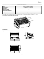
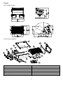
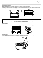
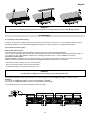
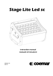
Stage Lite Led sc
instruction manual
manuale di istruzioni
Version 1.0
DIS131
Stage Lite Led sc
Serial number/numero di serie
Date of purchase/data di acquisto
Retailer/fornitore
Address/indirizzo
Suburb/cap/città
Capital city/provincial
State/stato
Tel./fax
Please note in the space provided above the relative service information of the model and the
retailer from whom you purchased your Stage Lite Led sc: this information will assist us in
providing spare parts, repairs or in answering any tecnica enquiries with the utmost speed and
accuracy.
Prendete nota, nello spazio apposite, dei dati relative al modello e al rivenditore del vostro Stage
Lite Led sc: questi dati ci permetteranno di assistervi con la massima rapidità e precisione.
WARNING: the security of the fixture is granted only if these instructions are strictly follone;
therefore it is absolutely necessary to keep this manual.
ATTENZIONE: la sicurezza dell’apparecchio è garantita solo con l’uso appropriato delle presenti
istruzioni, pertanto è necessario conservarle.
User Manual Version 1.0
edition October 2010
English
Index
1.Packaging and transportation ................................................................................................................ 6
1.1 Packaging ........................................................................................................................................... 6
1.2 Transportation ..................................................................................................................................... 6
2. General information................................................................................................................................ 6
2.1 Important safety information. ............................................................................................................... 6
2.2 Warranty conditions ............................................................................................................................ 6
2.3 EC norms. ........................................................................................................................................... 6
3. Product specifications ........................................................................................................................... 7
3.1 Technical characteristics ..................................................................................................................... 7
3.2 Dimensions ......................................................................................................................................... 7
3.3 Unit’s main components ...................................................................................................................... 8
4. Installation .............................................................................................................................................. 9
4.1 Mechenical installation ........................................................................................................................ 9
4.2 Safety chain ........................................................................................................................................ 9
4.3 Adjusting unit tilt ................................................................................................................................ 10
4.4 Replacing lenses ............................................................................................................................... 10
5. Powering up .......................................................................................................................................... 11
5.1 Operating voltage and frequency ...................................................................................................... 11
5.2 Connection to mains power ............................................................................................................... 11
6. Control signal connections.................................................................................................................. 12
6.1 Control signal connection by XLR3 plugs. ......................................................................................... 13
7. Turning on the projector ...................................................................................................................... 13
7.1 DMX address of the unit .................................................................................................................... 13
7.2 DMX functions................................................................................................................................... 14
8. Display panel functions ....................................................................................................................... 15
8.1 Quick guide to menu ......................................................................................................................... 15
8.2 Rapid count. ...................................................................................................................................... 15
8.3 MODE menu ..................................................................................................................................... 15
8.4 Test and measures (MEAS) .............................................................................................................. 16
8.5 Function settings (FUNC) .................................................................................................................. 16
8.6 Connecting DR1 and DR1 Plus ......................................................................................................... 17
8.7 Electronic led alignment.. .................................................................................................................. 17
9. Error messages .................................................................................................................................... 18
10.Spare parts ........................................................................................................................................... 19
11. Maintenance ........................................................................................................................................ 19
11.1 Periodic cleaning ............................................................................................................................. 19
11.2 Periodic controls.............................................................................................................................. 19
11.3 Sostituzione dei fusibili guasti.......................................................................................................... 19
12. FAQ and answers ............................................................................................................................... 20
5
English
Congratulations on having purchased a Coemar product. You have assured yourself of a fixture of the highest quality, both in the
componentry and in the technology used. We renew our invitation to you to complete the service information form on the previous
page. This will assist in providing prompt and accurate advice from your Coemar service centre, which you can thoroughly trust and
to which you can submit any requests for service or information. Following the instructions and procedures outlined in this manual
will ensure the maximum efficiency of this product for years to come.
1.Packaging and transportation
1.1 Packaging
Open the packaging and make sure that no part of the equipment has suffered any damage during the transportation. In case of
damage to the fixture, contact your currier and your supplier immediately by telephone, fax or email, and inform them you will
formally notify them in writing through registered letter.
Packing List
Make sure the packaging contains:
1 Stage Lite Led sc
2 This instruction manual.
3 Cam-Lock support brackets.
4-Cam Lock brackets for floor support.
1.2 Transportation
Stage Lite Led sc must be transported exclusively in its original packaging or in an appropriate flight case.
2. General information
2.1 Important safety information.
Fire prevention:
1.Never locate the fixture on any flammable surface.
2.Minimum distance from flammable materials: 0,5m.
3.Minimum distance from the closet illuminable surface: 0,5m.
4.Replace any blown or damaged fuse only with those of identical values. Refer to the schematic diagram if there is any doubt.
5. Connect the projector to mains power protected by a thermal magnetic circuit breaker.
Preventing from electric shock.
1. Presence of high voltage inside of the fixture. Insulate the projector from mains supply before opening or performing any function
which involves touching the inside of the fixture, including lamp replacement..
2. For the connection to the mains, adhere strictly to the guidelines outlined in this manual.
3. The level of technology of Stage Lite Led sc requires the use of specialised personnel for all service applications; refer all work
to your authorised Coemar service centre.
4. A good earth connection is essential for the proper functioning of the projector. Never connect the fixture if there is no earth
connection.
5.Mains cables must not come into contact with other cables.
6.Do not operate the projector with wet hands or in an area where water is present.
7.The fixture must never be located in an exposed position, or in areas of extreme humidity.
Safety.
1. The projector must always be installed with bolts, clamps, or other fixing devices which are suitably rated to support the weight of
the projector.
2. Always use a secondary safety fixing device with chain or steel wire of a suitable rating to sustain the weight of the unit in case of
failure of the principal fixing point.
3. The external surfaces of the unit, at various points, may reach 80°C. Never handle the unit until at least 10 minutes have elapsed
since the lamp was turned off
4. Never install the fixture in an enclosed area lacking sufficient air flow; the room temperature must not exceed 35°C.
5. The projector contains electronic and electrical components which must under no circumstances be in contact with water, oil or
any other liquid. Failure to do so will compromise the proper functioning of the projector.
Protection rating against penetration by external agents (versione IP65):
The fixture has an IP65 protection rating; this indicates that it is protected against dust and significant showers of water. This
protection rating allows the fixture to be installed in an exposed location in inclement weather conditions..
2.2 Warranty conditions
1. The fixture is guaranteed for a period of 12 months from the date of purchase against manufacturing or materials defects.
2. The warranty does not extend to damage caused by inappropriate usage, use by inexperienced operators or inadequate
maintenance.
3. The warranty is immediately void if the projector has been tampered or opened by unauthorised personnel.
4. The warranty does not extend to fixture replacement.
5. Both the serial number and the model of the projector are required for any advice or service from your authorised service centre.
2.3 EC norms.
The projector meets all fundamental applicable EC requirements.
6
English
3. Product specifications
3.1 Technical characteristics
Power
90-250 Vac 50/60Hz Autosensing
Maximum current
0,5 A @230 Vac, - 1°@115Vac
Power factor
Cos = 0,6
4A.
68 W
Light source wattage
Maximum room temperature
35°C/95°F
575 W
6 Kg./13.2 lbs
Weight
IP rating
IP20 (standard version) – IP65 (IP version)
The technological heart of Stage Lite Led sc is made of 48 powerful leds projecting infinite combinations of colors, mounted on
three parallel, 180° manually orientating bars. In the following pages, for convention, these bars are called lines and are
enumerated from the bottom line 1, line 2 and line 3.
Line 3
Line 2
Line 1
3.2 Dimensions
Suspended installation version
7
English
Floor installation version.
3.3 Unit’s main components
1
9
12
2
4
3
12
7
6
8
10
11
Components description
1- Top frame
7- Adjusting knobs
2- Polycarbonate screen
8- Unit housing
3- Internal led lines group
9- Left header
4- Right header
10- DMX IP20 panel
5- Led controller PCB
11- Display panel
6- Power supply unit
12- Gasket
8
5
English
4. Installation
4.1 Mechenical installation
Stage Lite Led sc may be floor mounted or hung from an appropriate structure in any position.
If hanging the fixture from a lighting truss or similar, we recommend the use of an appropriate clamp “B” affixed to the fixture in the
holes “A” provided, as shown in the following diagram.
A
B
WARNING!
Always ensure that your support structure and fixing (bolts, clamps, etc…)
are rated to support the weight of the fixture.
Floor installation
If the fixture is floor mounted, we recommend the use of appropriate clamps “C” as shown in the following diagram.
C
4.2 Safety chain
When hanging Stage Lite Led sc we recommend the use of a safety chain affine to the body and to the suspension device. The
safety chain should be either a metal rope or a metal chain, both suitably for the purpose.
D
9
English
4.3 Adjusting unit tilt
Stage Lite Led sc tilt, when floor mounted can be adjusted in a range of 120° as preferred. In order to adjust the tilt untight the “E”
handles sited on the sides of the supports, adjust the tilt angle as preferred then tight again the handles. Move the knobs in order to
orient the beams at the desired angle. The graduated board is a useful point of reference to achieve a sharp adjustment.
G
E
F
4.4 Replacing lenses
It is possible to mount optional lenses in order to get a different beam angle. The instruction for replacing the lenses are showed in
the following pictures. This operation must be done by qualified personnel.
-remove the frame or the IP65 panel from the bottom of the fixture by unscrewing the 4 screws, then remove also the other 2
screws placed underneath in order to unlock the inner block.
-remove the three adjusting knobs and the right side header from the fixture by removing the 7 screws; gently extract the inner
block from the body. Be careful not to tear cables that can be caught in the body.
- Replace the lenses needed taking care not to make pressure on the lens for any reason. If the operation is difficult to perform,
check for the correct orientation of the lens towards Its receptacle.
10
English
WARNING !!
Insert the lenses gently observing the points of reference. A wrong insertion can seriously damage the leds.
5. Powering up
5.1 Operating voltage and frequency
The unit may operates at voltages ranges from 90 to 250VaC at a frequency of 50 or 60 Hz. It is not needed to effect any setup
procedures, Stage Lite Led sc will automatically adjust its operation to suit any frequency or voltage within this range.
5.2 Connection to mains power
Mains cable characteristics
The mains cable provided is thermally resistant, complying to the most recent International standards.
Note: in case of cable replacement, similar cable with comparable thermal resistant qualities must be used exclusively (cable 3 X
1,5 ø external 10 mm, rated 300/500V, tested to 2 KV, operating temperature -40°C + 180°C, Coemar cod. CV5311).
Connection to mains power
Stage Lite Led sc is equipped with two power connectors, one as input and one as output, which can be used to connect more
fixtures in series.The maximum current absorbed from Stage Lite Led sc is indicated in the chart below:
-230/240V 0,5A amps constant current in normal operation.
-100/115V 1A amps constant current in normal operation.
The maximum working current of the connectors is 16A.
WARNING !
The absorbtion of Stage Lite Led sc (I max) can never be more than 16 A.
The maximum absorption Imax is given from the sum of the absorptions of all the Stage Lite Led sc connected in series.
Example:
For a series of 5 Stage Lite Led sc connected at 100V Imax = 1 X 5 = 5A
For a series of 5 Stage Lite Led sc connected at 230V Imax = 0,5 X 5 = 2,5A
In the following figure you can see an example of series connection:
11
English
WARNING!!
•The use of a thermal/magnetic circuit breaker is recommended. Strict adherence to regulatory norms is strongly
recommended.
•Stage Lite Led sc should not be powered through a dimmer as this may damage the internal switching power supply.
•Prior to connecting the device to mains power, ensure that the mains characteristics are within the recommended range
for use with the Stage Lite Led sc.
•all cabling and connections should be carried out by suitably qualified personnel.
6. Control signal connections
Stage Lite Led sc can operate in two modes:
1- using DMX512 control signal
2- automatic “STAND ALONE” or “MASTER/SLAVE” mode.
6.1 Control signal connection by XLR3 plugs.
The digital control signal is transmitted to the projector via a two pole cable screened as per International standards for the
transmission of DMX 512 data. The connection must be serial, using connectors XL3 male and female located on the back of
Stage Lite Led sc labelled DMX512 IN e OUT (see diagram).
Pin 1= GROUND
Pin 2= DATAPin 3= DATA+
ATTENZIONE !
Make sure that screening and conductors are not in contact one another or with the metal housing of the connector.
Pin#1 and housing never must be connected to the power supply unit.
12
English
7. Turning on the projector
After having followed the preceding steps described, proceed with the power supply and turn on the projector connecting it to the
mains power.
The display the software version installed on the internal microprocessors:
For example, when switched on Stage Lite Led sc may show:
(actual software version installed)
If the address continues to blink and the “NO DMX SIGNAL” message appears, it means that the DMX signal has not been
received. Check the connection cable and the mixer functioning.
7.1 DMX address of the unit
Each projector uses 8 address channels for its complete operation and is controlled by a DMX 512 signal (for further information,
see section 7.2, DMX functions).
DMX addressing
When powered up initially, each projector will show A001, which indicates DMX address 001; a projector thus addressed will
respond to commands of channel 1 to 8 from your DMX 512 controller. A second unit must be addressed as A016, a third as A024
and so on. The operation must be carried out on every Stage Lite Led sc which has an address different from A001.
Altering DMX address.
1. Press the + or – button until the display shows the required DMX address. The digits on the display will blink to indicate that the
variation has not been registered.
2. Press the enter key to confirm your selection. The digits on the display panel will cease to blink and the projector will now
respond to the new address.
Note: by holding the + or – button down the scrolling will be faster; thus allowing a faster selection
WARNING!
If you alter the DMX address with no DMX signal connected, the digits on the display panel will continue to flash
even after you have pressed ENTER button to confirm the address.
13
English
7.2 DMX functions
14
English
8. Display panel functions
By suitably using all the functions of Stage Lite Led sc, which can be activated through its display panel, it is possible to change
some of the parameters and to add some functions.
Changing the preset settings made by Coemar can vary the functions of the projector so that it will respond differently to the
controller; therefore carefully read about the functions described here before carrying out any possible selection..
8.1 Quick guide to menu
In order to access the functions, just press the menu button: one after the other, all the voices of the menu will be cyclically shown
each time the key + or – will be pressed. To select the desired function, press enter.
8.2 Rapid count
By the display panel of Stage Lite Led sc It is possible to quickly change the various numbers displayed for the different functions
in the following 3 manners:
1.Pressing the + or – buttons will cause the count to be quicker.
2.Pressing first + and then – and then holding them down simultaneously will cause the numbers to jump to the highest value.
3.Pressing first – and then + and then holding them down simultaneously will cause the numbers to jump to the lowest value.
8.3 MODE menu
The projector gives the opportunity to change and customize some functional settings.
DMX mode setting
MASTER mode setting
It let select the program to perform.
SLAVE mode setting
Duration of the sequence in seconds
Time interval of the sequenze in seconds
15
English
8.4 Test and measures (MEAS)
The internal microprocessor of Stage Lite Led sc allows for several diagnostic and output paramenter to be displayed.
Reading of internal
temperature.
Eg: Numeric value in °C
Reading of DMX value (0/255)
received by each channel of
DMX512 chain.
Eg: DMX value
~
Reading of DMX 512 signal
value.
Eg: DMX value
Eg: value
or
No DMX value
Reading of warning messages
sequenze (errors) shown after
reset operation.
Eg: error message
or
No alarm
Reading of the software
leasing code.
Eg: version code
Reading of the led’s frequency
flicker
~
Working time (in hours)
Numeric value in Hz.
Life of the leds
Eg: value
Life of the unit
Eg: value
8.5 Function settings (FUNC)
The projector gives the opportunity to change and customize some functional settings.
To set all the functions at the default values.
Test functions.
Enter to confirm
~
~
~
~
~
Test red
Test green
Test blue
Test white
Test strobo
To record the scene of the unit. If DMX
signal is not applied the recorder setting
will appear at the end of reset operation
when the unit is switched on..
Reverse display : it turns the
display of 180°
reverse
Enter to confirm
Standard visualization
Reverse visualization
It disables
buttons.
It disables the display
visaualization
It switch off the display after 6 sec.
Display always on
To set the unit’s ID number.
~
It starts the reset and allows the access to the led adjustment section.
16
Function enabled; push any
button for 5 sec. to wake up the
display.
Function disabled.
English
8.6 Connecting DR1 and DR1 Plus
All the menu functions can be remotely activated by DR1 (cod. CO9707) and DR1 Plus (cod.CO9709). DR1 and DR1 Plus are
instruments designed for technicians who need to operate on the fixtures whilst they may be located in inaccessible positions
without work directly on the fixture itself.
For example, DR1 and DR1 Plus eliminate the need for climbing up the truss structures to gain physical access to the projector to
alter such parameters as DMX address. DR1 and DR1 Plus allow also the firmware updating of the fixtures
To enable any fixture for operating with DR1 or DR1 Plus, you must first activate the identifying number of the projector (ID) which
menu,
must be unique in the particular DMX universe in which it is currently installed. To change the ID number enter in
choose
then change the ID number by + and – keys and confirm by enter key (see also
menu).
WARNING !
-If you set a unit’s identification number to “0” it will not be able to comunicate with DR1 o DR1 Plus.
-Never assign the same ID to two or more units. This may jeopardize the functioning of the entire system. ( DR1 and DR1
Plus will show an error message).
For further information, consult the DR1 or DR1 Plus manual.
8.7 Electronic led alignment.
The display of Stage Lite Led sc enables the alignment of the leds; this procedure has been done by Coemar before leaving the
factory. It may be needed to modify these settings in case of internal parts replacement. (PCBs , leds, etc..).
Modifying the settings made by Coemar may totally vary the behavior of the unit, so read carefully the following instructions before
operate.
WARNING !
This procedure should only be undertaken by qualified and experienced technical personnel.
To have access to the alignment function:
1- Press the menu button and then enter to confirm.
2- Press the + or – button until
is displayed. Press enter to confirm.
3- Press the + or – button until
is displayed.
4-Press the enter and menu buttons simultaneously, holding them for at least 10”. The motors will perform a reset and the display
will show ---- for a few seconds. After this, the display will show
confirming the entry in the electronic calibration mode.
WARNING !
The alignment procedure can only be carried out when DMX512 signal is connected.
Consult the following diagram to get more details.
17
English
With DMX signal connected
DMX press for 10” enter and
menu buttons together: the
display will show the folowing
diagram.
~
~
~
~
~
~
~
~
Alignment of red led at minimum intensity
Alignment of green led at minimum intensity
Alignment of blue led at minimum intensity
Alignment of white led at minimum intensity
Alignment of red led at maximum intensity
Alignment of green led at maximum intensity
Alignment of blue led at maximum intensity
Alignment of white led at maximum intensity
Software upload from DR1 +
Reading of progress value
Software downolad to DR1 +
Reading of progress value
To end the electronic calibration procedure and to record it.
Nota: Simultaneously pressing + and – buttons will return the calibration value to 128 (default).
UPLD Function (Upload)
this function allows to upgrade the firmware of Stage Lite Led sc only by DR1 or DR1 Plus and a Personal Computer. Read DR1
or DR1 Plus manual for further information.
DULD Function (Download)
this function allows to download the software from Stage Lite Led sc only by DR1 or DR1 Plus and by a Personal Computer. Read
DR1 or DR1 Plus manual for further information.
9. Error messages
If a malfunction occurs, Stage Lite Led sc has a self-diagnostic system that will show the error message on the display. The
following table will explain in detail the most common errors. If, despite of suggested intervention, the problem persists, call the
Coemar Service center near you.
Error message
Description and suggested solution.
Data error. The initial configuration settings are faulty or have been loaded incorrectly. The projector has loaded its default
configuration. Turn the projector off and on again and if the error persists, it means that the EEprom is either defective or
absent; refer to your Coemar service center for the replacement.
DMX address error. The projector is not receiving all the DMX channels necessary for its operation. Check the DMX address
and the control consolle operation. Note that some controllers may not generate all 512 channels of signal.
Master mode error. This message indicates that the user has attempate to set the unit to MASTER mode whilst DMX signal is
still being received. Detach any DMX control signal or remove MASTER mode settings on other units in the DMX chain.
18
English
10.Spare parts
All the components of Stage Lite Led sc are available as spare parts from your Coemar dealer or Service. Accurate description of
the fixture, model number and type will assist us in providing for your requirements in an efficient and effective manner.
11. Maintenance
11.1 Periodic cleaning
Polycarbonate screen
Even a fine layer of dust can reduce the luminous output and alter the compactness of the beam. Regularly clean all filters and
lenses using a soft cotton cloth, dampened with a specialist lens cleaning solution.
Cleaning of the unit
Use a soft brush or a common vacuum cleaner or a source of compressed air for removing dust from the heat sink on the back of
the unit. For the cleaning of the housing use a soft cloth and a non-aggressive cleaner.
11.2 Periodic controls
Mechanical parts
Check the correct working of the mechanical parts and, if needed, replace them. Make sure the projector is not mechanically
damaged. If necessary, replace the worn parts.
Electrical components
Check all electrical connections, in particular for correct grounding and correct attachment of all extractable connectors. Press the
connectors if necessary and reposition as before.
11.3 Sostituzione dei fusibili guasti
Check the conditions of the fuses using an appropriate instrument; if damaged, replace them with equivalent ones. The following
image shows position and value of the fuse.
Fuse: 6,15 A F 250V
19
English
12. FAQ and answers
Question
Possible cause
Suggested solution
Stage Lite Led sc does not turn on.
-Unit not powered:
1- check that the green led on the back
panel is lit.
2-The fuse may be blown.
1-Make sure the power cord is plugged in
or test the input voltage.
2-Turn off the unit and replace the blown
fuse.
Stage Lite Led sc does not respond, or
responds incorrectly, to DMX signal..
The DMX signal may not come to Stage
Lite Led sc.
Inspect the cable connection, correct
poor connections or inefficient repair or
replace damaged cables.
Check DMX address of the unit.
Stage Lite Led sc has been set as
MASTER unit but it do not run any
program.
1-Another Stage Lite Lite Led sc set as
MASTER is in the DMX chain.
2-Stage Lite Led sc receives a DMX
signal.
3-There wasn’t set any program.
1-Locate the other unit set as MASTER
and set it as SLAVE.
2-Remove eventual DMX connection.
3-Set a program on MASTER unit.
Stage Lite Led sc is not recognized by
DR1 or DR1 Plus.
ID set as 0 or another unit with the same
ID is in the DMX chain.
Change the setting of the ID number
different from 0 and different from any
other unit in the line.
Information on disposal of the equipment
The equipment at the end of its useful life must be disposed of at an appropriate recycling center for
waste electrical and electronic equipment. The treatment and disposal of environmentally friendly, helps
prevent potential negative environmental and health and promote the reuse and / or recycling of
materials making up the equipment. Illegal disposal by the user includes the application of administrative
sanctions provided by law.
20
Coemar s.p.a.
via Inghilterra 2/A - 46042 Castel Goffredo (Mantova) Italy
ph. +39 0376/77521 - fax +39 0376/780657
[email protected]
Coemar si riserva il diritto di apportare modifiche senza preavviso.
Coemar reserves the right to effect modifications without notification