1
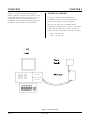
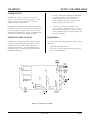
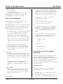
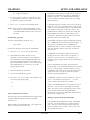
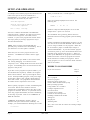
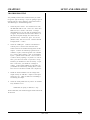
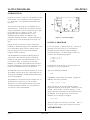
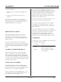
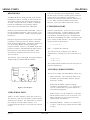
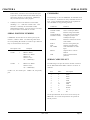
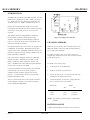
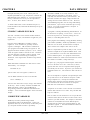
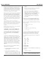
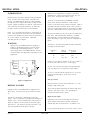
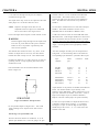
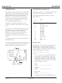
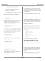
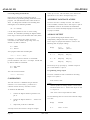
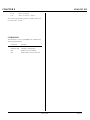
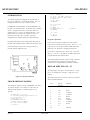
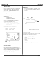
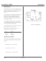
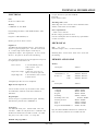
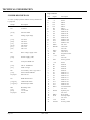
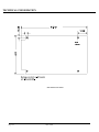
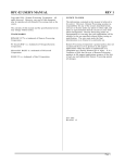
SBS-2300 USER'S MANUAL NOTICE TO USER Copyr ight 1999 - Re mote P rocessing Cor poration. All rights reserved. However, any part of this document may be reproduc ed with Remote Proce ssing cited as the source. The con tents of this ma nual and the sp ecifications her ein may change without notice. TRADEMARKS CAM BASIC II™ and PC Sm artLINK™ are trademar ks of Octagon Systems Corpor ation. Microsoft® BASIC is a trademark of M icrosoft Corpor ation. The infor mation co ntained in this m anual is believe d to be correct. However, Remote Pr ocessing assumes no responsibility for any of the circuits described herein, conveys no license under any patent or other right, and make no repre sentations that the circuits are free from patent infringement. Rem ote Processing makes no representation or warr anty that such applications will be suitable for the use specified without further testing or modification. The user must make the final determination as to fitness for a particular use. Remote Pr ocessing Corporation' s general policy does not recomm end the use of its products in life support or applications where the failure or malfunction of a board may threaten life or injury. Install redundant or backup safety systems as appropriate to the application. FCC AND EMI NOTICE The SBS-2300 is intended as an OEM pr oduct in an industrial environment. It was not tested for EMI radiation. When operated outside a suitable enclosure, the board and any cab les coming from the board will radiate harmful signals which interfere with consuer and industrial r adio freq uencies. It is your r esponsibility to proper ly shield the RP C-2300 and cables co ming fr om it to prevent such interference. Remote Pr ocessing Corporation 7975 E. Har vard Ave. Denver, Co 80231 Ph: (303) 690 1588 Fax: (303) 690 1875 www. rp3.c om P/N 1196 Revision: 1.2 RPC-2300 Page i TABLE OF CONTENTS DESCRIPTION . . . . . . . . . . . . . . . . . . . MANUAL ORGANIZATION . . . . . . . . . . MANUAL CONVENTIONS . . . . . . . . . . . Symbols and Term inology . . . . . . . . . TECHNICA L SUPPORT . . . . . . . . . . . . . INTRODUCTION . . . . . . . . . . . . . . . . . OPERATING PRECAUTIONS . . . . . . . . . EQUIPMENT . . . . . . . . . . . . . . . . . . . . FIRST TIME OPERATION . . . . . . . . . . . UPLOADING AND DOWNLOADING P R OG R AM S . . . . . . . . . . . . . . . . . Uploading programs . . . . . . . . . . . . . Downloading programs . . . . . . . . . . . Other communications software . . . . . . Editing pr ogram s and pro gram ming hints WHERE TO G O FROM H ERE . . . . . . . . . TROUBLESHOOTING . . . . . . . . . . . . . . INTRODUCTION . . . . . . . . . . . . . . . . . SAVING A PROGRAM . . . . . . . . . . . . . AUTORUNNING . . . . . . . . . . . . . . . . . . PREVENTING AUTORUN . . . . . . . . . . . LOADING AN EPROM PROGRAM . . . . . COMMANDS . . . . . . . . . . . . . . . . . . . . DESCRIPTION . . . . . . . . . . . . . . . . . . . COM1 SERIAL PORT . . . . . . . . . . . . . . COM2 SERIAL PORT . . . . . . . . . . . . . . ACCESSING SERIAL BUFFERS . . . . . . . SERIAL PORT FILE NU MBERS . . . . . . . COMMANDS . . . . . . . . . . . . . . . . . . . . SERIAL CABLE PIN OUT . . . . . . . . . . . INTRODUCTION . . . . . . . . . . . . . . . . . CHANGING M EMORY . . . . . . . . . . . . . BATTERY BACKUP . . . . . . . . . . . . . . . STORING VARIABLES IN RAM . . . . . . . CORRUPTED VARIABLES . . . . . . . . . . . ASSEMBLY LANGUAGE INTERFACE . . COMMANDS . . . . . . . . . . . . . . . . . . . . INTRODUCTION . . . . . . . . . . . . . . . . . DIGITAL I/O PORT . . . . . . . . . . . . . . . . Pull up resistors . . . . . . . . . . . . . . . . High current output . . . . . . . . . . . . . . Interfacing to an opto-module rack . . . . Configuring digital I/O lines . . . . . . . . Digital I/O progra mming . . . . . . . . . . Connector pin out . . . . . . . . . . . . . . . COMMANDS . . . . . . . . . . . . . . . . . . . . DESCRIPTION . . . . . . . . . . . . . . . . . . . INSTALLATION . . . . . . . . . . . . . . . . . . S E TT I NG D A TE A N D T I M E . . . . . . . . . . COMMANDS . . . . . . . . . . . . . . . . . . . . INTRODUCTION . . . . . . . . . . . . . . . . . C ONNE C T IN G A N A L OG I/O . . . . . . . . . Initializing Inputs . . . . . . . . . . . . . . . Page ii . . . . . . . . . . . . . . . . . . 1 1 1 1 2 4 4 4 5 . . . . . . . . . . . . . . . . . . . . . . . . . . . . . . . . . . . . . . . . . . . . . . . . . . . . . 5 5 6 6 6 7 8 9 9 9 10 10 10 11 11 11 11 12 12 12 13 13 13 14 14 15 15 16 16 16 16 17 18 18 18 19 20 20 20 20 21 21 21 RPC-2300 ACQUIRING ANALOG DATA . . . . Datalogging on a timer tick . . . . . MEASURING HIGHER VOLTAGES Conve rting analo g measu rem ents . CALIBRATION . . . . . . . . . . . . . . ASSEM BLY LAN GUAG E ACC ESS . ANALOG OUTPUT . . . . . . . . . . . . Program ming voltage output . . . . COMMANDS . . . . . . . . . . . . . . . . INTRODUCTION . . . . . . . . . . . . . PROGRAMMING EXAMPLE . . . . . KEYP AD P ORT P IN OU T - J5 . . . . . COMMANDS . . . . . . . . . . . . . . . . DESCRIPTION . . . . . . . . . . . . . . . Connecting a speaker . . . . . . . . . Prog ram ming exa mple . . . . . . . . DESCRIPTION . . . . . . . . . . . . . . . PROGRAM EXAMPLES . . . . . . . . ELECTRICAL . . . . . . . . . . . . . . . MECHANICAL . . . . . . . . . . . . . . MEMORY AND I/O MAP . . . . . . . . JUMPER DESCRIPTIONS . . . . . . . . . . . . . . . . . . . . . . . . . . . . . . . . . . . . . . . . . . . . . . . . . . . . . . . . . . . . . . . . . . . . . . . . . . . . . . . . . . . . . . . . . . . . . . . . . . . . . . . . . . . . . . . . . . . . . 22 22 22 22 23 23 23 23 24 25 25 25 26 27 27 27 28 28 29 29 29 30 CHAPTER 1 OVERVIEW DESCRIPTION MANUAL ORGANIZATION The SBS-23 00 is an em bedded co ntroller with a built in Basic language. Several featur es make it suitable as a stand alone un it: This m anual pro vides all the infor mation r equired to install, configure, and use the features on the SBS-2300. This manual assumes you are fam iliar with some type of BASIC progr amming software. The syntax used by CAM BASIC II is similar to Microsoft' s GW or QuickBASIC. If you are not experienced with BASIC software, you may want to refer to books and training programs available through your local software store. The CAMBA SIC II Programming Manual has information and e xamples for a ll commands. Built in CAMBASIC II progr amming language autoruns at power up. On card flash EPROM programmer saves programs to 30K. Eight single e nded or 4 differen tial analog inputs convert voltage inputs to a digital value using a 12 bit (4096 count) A/D converter. Two analog outputs are available. NOTE: The SBS-2300 uses a Hitachi Z180 processor. Additional information can be obtained from Hitachi or a local representative. Or der hardwar e manual #U77, software manual #U92. Keypad port for operator interface. The 16 position keypad is automatically scanned and is read using the KEYPA D comm and. Two RS-232 serial ports are pr ogramm able for baud MANUAL CONVENTIONS rate, par ity, length, and stop bits. Both inputs and outputs have a 256 byte buffer. Information appearing on your screen is shown in a different type. Watchdog timer resets the card if the program "crashes" . The time r is enabled and disabled by software. Example: 48 general purpose digital I/O lines, 8 of which are CAMBASIC II (tm) V1.00 (c) 1985-94 Octagon Systems Corporation (c) 1994 Remote Processing Corporation All rights reserved - free 29434 high curr ent outputs. These lines can connec t to another opto rack. 128K of RAM is standard, with a 512K RAM Symbols and Term inology optionally available. RAM is optionally battery backed using a DS-1213D. NOTE: Text under this heading is helpful information. It is intended to act as a reminder of some interaction with another part of the manual or device that may not be obviou s. Built in EPROM pr ogramm er save program s for autorun on power up or r eset. The SBS-2300 uses a 64180 CPU oper ating at 9 Mhz. It operates stand alone or on a network using RS-485 adapter. Its 4. 5" x 8" size ma kes it easy to mount in a NEM A box. WARNING: CAM BASIC II progr amm ing language is standard . T his language was adapted for the SBS-2300 for control an d data acquisition applications. A com plete description of CAMBA SIC II commands is in the CAMBASIC II Programming Guide. W[-] Information under this heading warns you of situations which might cause catastrophic or irreversible damage. < xxx> Denotes jump er block pins. Paired angle brackets are used to indicate a specific key on your keyboard. F or example < esc> means the escape key. Program development can take place on your PC, using your word processor, or on the SBS-2300. Programs from your PC can be downloaded using PC SmartLINK or other serial communication program. RPC-2300 Page 1 OVERVIEW BASIC uses decimal convention for designating addresses and data. There are times, however, when hexadecimal notation is more convenient to use. The hexadecimal notation used in this manual and by CAMBASIC II is the ampersand character (&) before the numb er. A &8C stands for 8 C hexa decima l. CHAPTER 1 TECHNICAL SUPPORT If you have a question about the SBS-2300 or CAM BASIC II used on it and c an' t find it in this manua l, ca ll us and ask for technical supp ort. When you call, please have your SBS-2300 and CAM BASIC II manuals ready. Sometimes it is helpful to know what the SBS-2300 is used for, so please be ready to describe its application as well as the problem. Phone: 303-690-1588 FAX: 303-690-1875 Figure 1-1 System layout Page 2 RPC-2300 CHAPTER 2 SETUP AND OPERATION INTRODUCTION 1. Ground yourself before handling the SBS-2300 or plugging in cables. Static electricity can easily arc through cables and to the card. Simply touching a metal part on your PC can greatly reduce the amount of static. 2. Do not insert or remove components when power is applied. While the ca rd is a + 5 volt only system, other voltages are generated on the card. Applying them in the wrong sequence can destroy a compon ent. The SBS-2300 is ready to program as soon as you connect it to a ter minal or PC a nd apply pow er. This chapter describes what is needed to get a sign- on message and begin program ming. Requirements for uploading and downloading programs is discussed. A "W here to go from here" section dire cts you to the chapters to read in order to use the various capabilities of the SBS-2300. Finally, a troubleshooting section helps out on the most com mon pro blems. OPERATING PRECAUTIONS EQUIPMENT The SBS-2300 is designed to handle a wide variety of tempera ture range s and operating conditions. These character istics require using C MOS components. CM OS is static sensitive. T o avoid damaging these components, observe the following precautions before handling the SBS-2300. You will need the following equipment to begin using the SBS-2300: SBS-2300 embedded controller PC with a serial port and communications program (such as PC SmartLINK) Figure 2-1 Connector Locations RPC-2300 Page 3 SETUP AND OPERATION CHAPTER 2 The SBS-2300 does not send a CTS signal to the PC or terminal. If your terminal or comm unications software requires this or other signals (DCD , D SR), you may have to tie them to the appropriate leve ls. You may be able to ignore these lines in software. (Equipment continued) VTC -10 serial c able + 5, 3 00 ma po wer su pply The CAMBA SIC II Programming Manual is strongly recomm ended. Refer to Chapter 4 Se rial Ports for wiring information to make your own cable. 3. FIRST TIME OPERATION CAMBASIC II (tm) V1.00 (c) 1985-94 Octagon Systems Corporation (c) 1994 Remote Processing Corporation All rights reserved - free 29434 Become familiar with the locations of the connectors before getting started. See Figure 2-1. SBS-2300 jum pers hav e been set at the factory to o perate the system immediately. F or first time operation, do not install any connectors or parts unless specified below. Jumpers sho uld be kept in default positions. 1. The SBS-2300 needs + 5 ±0.25 volts at less than 300 ma. Any we ll regulated supply that supplie s this will work. Be careful when using "switching" power supplies. Som e of these supplies do not regulate properly unless they are adequately loaded. If a nonsense message appears, your terminal or PC may not be set to the appropriate communication parameters. If the system still does not respond, refer to "T ROU BLESH OOT ING" later in this chapter. 4. FOR X = 0 TO 2 PRINT " Hello "; NEXT PRINT Now type RUN You can use either a PC o r CR T term inal to program the SBS-2300. Connect one end of the VTC-10 connector to then 10 pin COM 1 (console) port on the SBS-2300. Refer to Figur e 2-1 for connector location. The system will display: Hello Hello Hello Using a PC Connect the VTC-10 serial cable to the PC' s COM1 or COM 2 port. Y ou may need a 9 pin male to 25 pin female adapter. T he VTC -10 is designed to plug directly into the 25 pin serial port connector on a PC. Start up your serial communication program (PC SmartLIN K or other). Set communication parameters to 19. 2K baud, 8 data bits, no par ity, 1 stop. The system is now in the " imme diate mod e" and is ready for you to start program ming. T ype the following program (in upper or lower case: 10 20 30 40 Make sure pow er is off. Connec t the power supply to the appropriately marked term inals on the SBS2300. 2. Turn on your pow er supply. On pow er up a copyright message is printed. UPLOADING AND DOWNLOADING PROGRAMS Downloading program s means transferring them fr om your PC (or terminal) to RAM on the SBS-2300. Uploading means transferring programs from RAM back to the PC. This section explains how to do both of these procedures using PC SmartLink. Gener alized instructions for other terminal program s are given at the end of this section. Uploading programs Using a Terminal Follow your term inal instructions to set the baud rate to 19.2K baud, 8 data bits, no parity, and 1 stop. You m ay need a 9 p in male to 25 pin female adapter to connect the VTC-10. In the previous section, you wrote a test program. To upload that program to a PC and save it to disk: 1. 2. PC or Term inal Page 4 RPC-2300 Pre ss the < F1> key. A windo w with the main menu will appear. Press the letter U (upper or lower case). Your program will begin to transfer from RAM to the CHAPTER 2 SETUP AND OPERATION CAM BASIC II does not know when you are typing in a progr am or if something else (laptop or mainfr ame) is sending it char acters. The uploa d and dow nload file does not conta in any special c ontrol cod es, it is sim ply ASCII cha racters. PC. When m enu appears. 3. To save a program to disk, type the letter S. You are prompted for a file name. Enter the file name you want the program saved under. 4. Press < F2> to return to the immediate mode. Uploading programs is simply a process of receiving an ASCII file. Y ou or your progr am simply needs to send "LIST " to receive the entire program . The default baud rate (19200) is rather high. M ake sure your PC and comm unications software ca n work at these bau d rates. PRO COM M w as tested on a 12 Mhz 2 86 PC and it worked fine. Windows Term inal on the same PC had problems at m uch slower ba ud rates. NOTE: Some ve rsions of P C Sm artLI NK hav e pull down menus or will operate differently. Refer to the SmartLINK m anual for the version you are using. Downloading programs Downloading a program requires transmitting an ASCII file. CAMBASIC II is an incremental line compiler. As you type in (or download) a line, CAM BASIC II compiles that line. The time to compile a line depends upon its complexity and how many line of code have been entered. To practice downloading a program , type NEW< return> Perform the following when using PC SmartLINK: 1. Press the < F1> key to view the main menu. 2. Smar tLINK has a buffer which is used to temporarily store the program. If you followed these instructions without exiting SmartLINK, the previously uploaded program is in the buffer and may be dow nloaded. Howeve r, lets assume you just started SmartLIN K. P ress the L key to get the program from the disk. 3. Enter the filename to get the file. 4. Press D to download the program. 5. Press the < F2> key to return to the program. You can list the program by typing: CAMBASIC II must finish compiling a line before s ta rting the ne xt one. W he n a line is compile d , a "> " character is sent by the card. T his should be your terminal program s pacing character when downloading a program. If your communications program cannot look for a pacing prompt, set it to delay transmission after each line is sent. A 100 ms delay is usually adequate, but your CAM BASIC II program may be long and complex and requir e mor e time. A resu lt of a short de lay time is missing or gar bled progra m lines. CAM BASIC II sends out escape sequences to clear the screen. T his sequence may appear as < -; on your screen. Usually this will not be a problem. list COM 1 on the SBS-2300 does not recognize the CTS or RTS lines. T he CTS line is pulled high on the SBS2300. The effect of not recognizing these lines is your PC or terminal cannot hold off the SBS-2300's transmission. C onverse, the SBS-2300 cannot hold off the host from sending it data. or / Other communications software The following is general information when using another terminal emulation program (Procomm, Windows Term inal, etc.). When uploading or downloading files, select ASCII text format. Other forma ts are not used. Editing programs and program ming hints Files uploaded or downloaded are simply ASCII DOS text files. No special characters or control codes are used. You m ay create and edit programs using your favorite word processor or editor. Just be sure to save files in DO S text form at. RPC-2300 Page 5 SETUP AND OPERATION CHAPTER 2 When you listed this line, it would appear as: A technique used to further program documentation and reduce code space is the use of comments in a downloaded file. For example, you could have the following in a file written on your editor: 10 FOR A = 0 TO 5 Spaces are initially displayed but not stored. The following line: 'Check VAT temperature 'Read the output from the RTD and ' calculate the temperature 10 for a 2200 a = ain(0) :'Get temp to 5 The CAMBA SIC II Programming Manual has more information about increasing program speed and editing options. NOTE: Some versions of PC SmartLINK may optionally strip comments before downloading. Check your manual to see if this option is available. Notice that you can w rite a progr am in lower case characters. CA MBASIC II translates them to upper case. Some program mers put "N EW" as the first line in the file. During debugging, it is common to insert "temporary" lines. Adding NEW ensures that these lines are gon e. D ownloadin g time is incr eased wh en the old progr am is still pre sent. Instead of uploading and downloading programs, you can save them to the on car d flash EP ROM . T his is useful if you are using a terminal to write programs. Make sure the 'A UTORU N' jumper is installed (See Chapter 3 SAVING PROGRAMS). To prevent automatic program execution on power up, inser t the STOP statement at the beginning of the program (such as line 1). When you power up the SBS-2300 , the progr am is tra nsferr ed into RAM and executed. Delete the progr am line with the STOP statement to normally start programs. When saving programs, be sure to reenter the STOP statement with its line number. WHERE TO GO FROM HERE If you want to do this: If you like to write programs in separate modules, you can download them separately. M odules are assigned blocks of line numbers. Start up code might be from 1 to 999. Interrupt handling (keypad, serial ports) might be from lines 1000 to 1499. Display output might be from 1500 to 2500. The program mer m ust determine the number of lines required for each section. When replacing a program or section, downloading time is increased. Blocks of line numbers cannot be renumber ed by CAM BASIC II when other parts of the program are installed. However , if a particular section is the only program downloaded, then line renumbering in that range is possible. Refer to the CAM BASIC II RENU M comm and. CAM BASIC II automatically formats a line for minimum code space and increased r eadability. For example, you could download the following line of code: Page 6 0 would be compressed and displayed as in the second example above. Spaces ar e removed. The first 3 comments downloaded to the SBS-2300 would be ignored. Similarly, the empty lines between comm ents are a lso ignored . L ine 2200, with its comment, is a part of the program and could be listed. The m ajor pena lty by wr iting a progr am this w ay is increased download time. 10 fora=0to5 = Save a program Autorun a program Know m ore abo ut serial por ts Install a differ ent RAM mem ory chip Battery backing up RAM Using RAM to save variables Configure digital I/O lines Get switch status Use high c urre nt outputs Connect an external opto rack Installing calend ar/ clock mo dule A nalog I/O Keypad port Watchdog timer Turn to Chapter 3 3 4 5 5 5 6 6 6 6 7 8 9 11 Also, r efer to the table of contents for a listing of major functions. RPC-2300 CHAPTER 2 SETUP AND OPERATION TROUBLESHOOTING You pr obably tur ned to this section b ecause you could not get the sign on message. If you are getting a sign on message but can' t enter characters, then read section 5. The following ar e troubleshooting hints: 1. Check the pow er source . If it is below 4. 65 volts, the SBS-2300 will be reset. Power is 5 ±0.25 volts. Make sure it is a clean 5 volt source. If it dips intermittently to 4. 65 volts (due to switching noise or ripple), the car d will reset for about 100 ms. If the noise is fre quent enoug h, the card w ill be in permanent reset. Check U14, pin 6. If it is low (about 0 volts), then it is in reset. This line shou ld be high (about + 5 volts). 2. Check the COM1 port. COM 1 is also known as console port J1. Rem ove the connector from COM 1. R efer to the outline dra wing ear lier in this chapter. Connect an oscilloscope (preferred) or a voltmeter to pin 3 (Txd ) and gro und. Pin 3 should be -6 volts or more negative. (Pin 1 is designated by the ^ sym bol on the conn ector. Pin 3 is next to it, nearer the key opening.) If you have -6 volts or more, press the reset switch. If you have a scope attached, you should see a burst of activity. If you have a volt m eter, you should see a change in voltage. Using a Fluke 8060A set to measure AC, you should see a mom entary rea ding above 2 volts. Pre ss reset sev eral tim es to make sure it captu res it. 3. Install the cable and make sure the voltages and output activity are still there. Output is from pin 3 on the VT C-10. Check to make su re som ething is not shorting the output. 4. Check the serial pa ram eters on y our P C or termin al. They should be set to: 19200 baud, no parity, 8 data bits, 1 stop If all of this fails, call technical support listed at the front of the book. RPC-2300 Page 7 SAVING PROGRAMS CHAPTER 3 INTRODUCTION Programs are stored in socket U3. An optional real time clock mo dule, a DS-12 16EM may also b e installed in U3. See Chapter 7 for calendar/clock installation and operation. You can store one program up to a maximum size of about 28K bytes. A general rule to determine program storage requirements is one line requires 40 bytes. 28K bytes would store over 700 lines of code. Your application could be significantly mor e or less, depending upon the number of commands / line, comments, and print statements. Another indication of program size is to use the file length as saved on a PC disk. Figure 3-1 Autorun jumper SAVING A PROGRAM Despite the fact you may have 128K or 512K RAM installed, the maximum progr am size CAMBASIC II can run is about 28K (leaving room for variable storage). Only one program can be stored on the EPROM. Program s cannot be chained. A flash EPROM is non-volatile (retaining data even when power is disconnected), having an unlimited numbe r of re ad cycles an d a limited nu mber of write cycles (about 1,000). A program is not run fr om EPROM . It is transferred to RAM and run from there. Programs in RAM are run and can be modified. They can be saved to EPROM for auto execution later. 10 20 30 40 FOR N = 0 TO 2 PRINT "Hello "; NEXT PRINT If this progr am is not alr eady in, type it in now (o r, if you prefer, use your own progr am). The SBS-2300 can be set to autorun on power up or reset by installing a jumper (W 1[9-10]). When autor un is on, the program in EP ROM is loaded into RAM and begins to execute immediately. The EP ROM is write-protected w ith a software lock, so accidental writes on pow er-on or -off are almost impossible. You cannot disable the lock except when executing the SAVE comma nd. T o save param eters, you must use battery backed RAM. To save a program, set jumper W1[9-10]. You may set the jumpe r even if the power is on. R emem ber to discharge any static electricity before installing or removing the jumper. For this example, assume you wanted to save the following program: Type in the following command: SAVE CAM BASIC II will compile the program, program the EPR OM, and verify its contents. Compile...Write...Verify The time it takes to do all of this depends upon the length and co mplexity of the progr am. Gener ally, it w ill be from 1 to 20 second s. T he read y prom pt (> ) will appear when the p rogr am has b een succes sfully saved to the EPROM . If the program does not write to the EPROM, an error message will appear: Fail @ xxxx Saving a pr ogram overw rites the pr evious one. Ther e is no way to recover it since both occupy the same space. AUTORUNNING Page 8 RPC-2300 CHAPTER 3 SAVING PROGRAMS If you need more than 2K bytes of data, you can save data "on top" of the CA MBASIC II program in U 3. A good way to determ ine how m uch mem ory is ava ilable is to perform a P RINT SY S(0) in the immediate mode (program not r unning). Subtracting 31900 from the numbe r of bytes r eturned will tell you the app roxim ate number of bytes available for data. To autorun a program: 1. Make sure there is a program in EP ROM (from above). 2. Make sure the a utorun jum per W 1 [9-10] is installed. The best way to make sure your data will not write over the progra m is to perfor m the following steps: If you push the reset button , the progr am shou ld autoexecu te. If th ere ar e any er rors , the progr am w ill stop (assuming you have not trapped them with ON ERROR) and display the error message. First, put a remark statement that you can recognize. One suggestion is "End of the program ". Next, save your program to the EPROM using the CAMBASIC II SAVE com mand. Remove the EPROM and read it from your EPROM program mer. Using your program mer, go into the mode where you can examine data. Look for the remark statement at the end of the program. Instruct the programmer to put your data starting at the next even page boundary (for example 5000H , 5100H , and so on). PREVENTING AUTORUN When troubleshooting a program , it' s not always convenient fo r an autoe xecute file to r un. This is especially tr ue if the pro gram has been co nfigured to ignore the < ESC> key. To pr event autorun, re move jumper W1[9-10]. COMMANDS The following is a list of CAM BASIC II commands used for saving and loading pr ogram s. Later, if you wish to SAVE or LOAD a program, reinstall this jumper. You may do so even if the power is on and a program is running. Remember to discharge any static electricity before installing or removing the jumper. LOADING AN EPROM PROGRAM Comm and Function LOAD Tra nsferr s progr am fr om U 3 to RAM for editing or running. Saves a pr ogram from RAM to U3 for autorun. SAVE Ther e are tim es when y ou may w ish to tempor arily modify or otherwise test out a change to a program. Since the program is loaded into RAM, modifications can be made without affecting the program in EPROM. If you find out tha t modification s are not de sirable or did not work, you can restore the original program to RAM using the LOAD com mand. SAVING DATA TO EPROM Additional data, such as strings and constants, can be saved to the EPROM in U3. An external EPROM progr amm er is used to sa ve data to the E PRO M. Data cannot be saved to U3 through CAM BASIC II. Data is saved at the top of the EPROM m emory. The upper 2K bytes are always available as RAM memory size absolutely limits the program to 30K. RPC-2300 Page 9 SERIAL PORTS CHAPTER 4 This port is normally used for program ming. D uring run tim e it may be u sed as a gene ral pur pose seria l port. When used for programming or with the INPUT statement, it will accept ASCII character values from 0 to 127. When used with the INKEY$ and COM$ functions, it will return ASCII values from 0 to 255. DESCRIPTION The SBS-2300 has two serial ports that can be used for interfacing to a printer , ter minal, or other ser ial devices. This chap ter descr ibes their ch aracter istics and how to use them. F requent references ar e made to comma nds listed in the CAMBA SIC II Programming Manual . Please refer to this manual for mor e information. COM2 SERIAL PORT Serial por ts are num bered C OM 1 and CO M2. COM 1 is used for program development. During run time, it can be used for other functions. C OM2 is a general purp ose RS-232 po rt. Both ports sup port XO N/ XOF F pr otocol to contr ol data transmission. Each por t has a 256 character interrupt driven inp ut and output bu ffer. This allow s charac ters to be sent out (using PRINT) without slowing down program execution. Howeve r, if the PRINT buffer fills, program execution is suspended until the buffer em pties. Both ports have a 256 character input buffer. When more than 256 character s have been rece ived, exc ess ones are ignored. COM 2 is an RS-232 port. It also uses a VTC-10 serial cable, described above. COM2 is identical to COM1 except that COM 2 has 2 hardw are handshaking lines, CTS and RT S. W hen RT S goes low, the SBS-2300 is held off fr om tra nsmitting out C OM 2. T he status of this port is read by the BIT statement. The exam ple below returns the status of the RTS line: 100 B = BIT(130,5) If B = 1, transm ission is held off. The CT S line may be set high or low to hold off comm unication. Line 400 se ts CTS low and 50 0 sets it high. The baud rate, parity, data length, and stop bit length are changed using the CONF IG BAUD command. 400 BIT 128,4,1 500 BIT 128,4,0 The CO NFIG BAUD statement sets both serial ports for baud rate and data type. ACCESSING SERIAL BUFFERS You can access C OM1 and COM 2 buffers in three w ays: 1. When using the INPUT statement, program execution is susp ended until a < cr> (Enter key) is received. W hether this is a problem depends on your particular application. Figure 4-1 Serial ports COM1 SERIAL PORT COM 1 is J1 and is called the Console port on the card. This port uses a VTC-10 serial cable to connect external serial dev ices to the por t. T he cable con sists of a 10 pin IDC connector w ired to a DB-9 connector. T he connector plugs directly into a 9 pin serial port connector on a PC. Page 10 INP UT sta tement. This re moves a ll charac ters in the buffer up to the term inator cha racter and puts them into a variable. INPU T strips bit 7 on the COM1 por t. This means ASCII character s from 0 to 127 are received. The INPU T statement can return a maxim um string length of about 150 chara cters. 2. RPC-2300 INKEY$(n) function. Characters ar e removed one at a time. A null string is returned when the buffer is empty. CHAPTER 4 SERIAL PORTS COMMANDS In this mode, you have access to the full 256 bytes. If you don' t read the b uffer an d the buffer fills, all subsequent characters are discarded. INKEY$(n) may be used anywhere in the program. 3. The following is a list of CAM BASIC II commands used for serial I/O. Var iations for many commands not listed here. These co mma nds and func tions are ex plained in the CAM BASIC II Program ming M anual. COM$(n) retrieves all characters in the buffer, including < cr> ' s and other control co des. This function is commonly used with ON COM$ multitasking statement. You can retrieve 128 of the 256 bytes in the serial buffer at one time. SERIAL PORT FILE NUMBERS CAM BASIC II refer ences the ser ial I/O ports by file numbers, similar to DOS. The following table shows the corresponding file number to serial I/O por t and how they are used w ith the various ports. Description File Comm and Function C L E AR C O M $ COM$ CONFIG BAUD C O N F IG C O M $ Clears serial input buffer Returns string from buffer Sets serial port parameters Configures port for ON COM $(n) interrupt Returns a character fr om the serial buffer Receives string from port Outputs program listing Calls subroutine on serial input Outputs data in various form ats Tabs to predetermined positions INKEY$ INPUT LIST O N C OM $ Examples PRINT COM1 COM2 1 2 PRINT "Hello" PRINT #1," Hello" INPUT A$ INPUT #1,A$ A$ = INKEY$(1) SERIAL CABLE PIN OUT PRINT #2," Hello" INPUT #2,A$ A$ = INKEY$(2) The following is the pin out between the IDC connector for the SBS-2300 and the DB-9 connector to the PC or term inal. TAB COM1 is J1, the console port. COM2 is J4, the primary port. IDC 1 2 3 4 5 6 7 8 9 10 DB-9 Description 4 3 2 1 5 n/c 8 7 n/c n/c DCD RXD TXD DTR Ground DSR CTS out RTS in + 5V RI Not all pins/functions on the VTC-10 are used by the SBS-2300. See Technical Information for specific J1 and J4 pin outs. RPC-2300 Page 11 DATA MEMORY CHAPTER 5 INTRODUCTION The SBS-2300 is available with 128K of RAM. A 512K RAM m ay be installed at any time. RAM is in socket U2. RAM m ay be battery backed by installing a DS1213D in socket U2. RAM is installed on top of U2. Battery life will depend upon RAM size, its power consumption, and am ount of time the board is operating. Generally, a battery life from 5 to 10 years can be expected. This chapter discusses changing RAM, installing a battery backup for RAM , saving and retrieving variables, and running assem bly language progr ams. F igu r e 5 -1 sh o ws th e lo catio n of U 2 an d jump ers W 4 and W7 (for RA M size change). Increasing RAM size does not increase the program size CAM BASIC II can handle. M aximum progr am and variable size is 30K. Additional RAM does increase the amount of variable and string storage available using the PEE K and POK E comm ands. Due to the memory mapping scheme, the additional amount of memor y available when a 128K or 512K RAM is installed is 32K less than the memory size. Thus, a 128K RA M pr ovides 96K of progr am and d ata memory and a 512K provides 480K. If program and data are battery backed, the UNNEW command may be used to restore the program. Variables used by the Basic program are clear ed, howeve r. Cer tain variab les are pr eserve d and data POKEd into RA M is saved. There is an interaction between the speaker and when 512K of RAM is installed. This is discussed below under CHANGING MEMORY. F ig u re 5- 1 J um p er s W 4 an d W 7 CHANGING MEMORY Different types of memory can be installed at any time. SBS-2300 models come with 128K of RAM installed. Up to 512K can be installed. To change a mem ory chip, you need to rem ove the original chip, install the new one, and set jumpers W 4[23] and W7[1-2][3-4]. To install a new memory chip: 1. Turn off power to the SBS-2300. 2. Remove the mem ory chip from U 2. 3. Orient the chip so pin 1 is closest to the card edge. Install the new chip into the sock et. 4. Check and change, as necessary, jumpe r W4 and W7 to conform to the new m emory. RAM size 128K 512K Jumper W4 W7 [1-2] [2-3] [1-3][2-4] [1-2][3-4] NOTE: The spea ker is disab led when a 512K RA M is installed. BATTERY BACKUP A Dallas Semiconductor DS-1213D is used to battery Page 12 RPC-2300 CHAPTER 5 DATA MEMORY backup R AM when pow er is off. Battery life w ill depend upon RAM size, type, tem perature, and time the SBS-2300 has power applied to it. You can expect the battery to last between 5 to 10 years for operation at 25°C. At 50°C, life is about 1/2 as much. To install a DS-1213D, r emove the RAM chip in U2, install the DS-1213D, and install the RAM chip on top of the module. The nature of RAM is it is easily written to. Any POK E' d data is susceptib le to corr uption. This is especially true when the board is powered down. The DS-1213C m onitors the supply voltage and turns off writing when it is below about 4.65 volts. However, when POKE ing long data, such as strings and floating point numbers, a pow er down could interrupt a saving process. T he result is information is corrupted. A scenario is explained below. A program is running and POKEing data into RAM. At the same time it is poking, a reset occurs. A reset can occur due to power loss, someone pushing the reset button, or a wa tchdog time r time o ut. STORING VARIABLES IN RAM The term "var iables" in this context includes numb ers, strings, arr ays, recipes, and formulas as applied to your application. If the program was P OKEing a string (POKE $), floating point number (FPOKE), double byte (DPOKE ), or arr ay while the reset occurred, the data became corrupted. This is because the complete value was not saved. Prog ram s and CA MBA SIC II va riables r eside in segmen t 0. Y our var iables are genera lly stored in segment 1 and higher. 32K of R AM is available for your program and variable storage in segment 0. The program and basic variables (A, B(15), C $, etc. ) always reside in segment 0 and are cleared on reset. Variables you peek and poke to usually reside in segment 1 and above. Var iables referenced by peek and poke statements. Each segment has an address range from 0 to 65535. Since it is impossible to predict or delay a reset, a work around is to duplicate or triplicate POKEd values. That is, you would have to save the same information in two or three different places. F or purposes of discussion, POKE d variables are called sets because data can consist of a mixture of va riables, strings and arr ays. On power up, your program would compare values from one set to the other one or two. If the two (or three) agreed, then there was no corruption and the program can reliably use the values. In practice, you would read information from set 1, but would save data to all two or three. PEEK and PO KE commands store and retrieve values from memor y. For example: 20 POKE 12,A,1 puts the value of A into segment 1, address 12. Use the PEEK statement to retrieve the variable: 50 B = PEEK(12, 1) You can store and retrieve arrays, strings, and variables in this way. There ar e many variations of PEE K and POKE statements. Refer to the CAMBA SIC II Programming Manual for additional information and examp les. A list of comm ands appea rs at the end of this chapter. CORRUPTED VARIABLES RAM m ay be battery backed using a Dallas Semiconductor DS-1213D Smartsocket. W hen your application must rely on the accuracy of data after power up, corr upted variables becomes a possibility. The use of duplicate or triplicate sets depends upon what the system must or can do if data is corrupted. W hen using a duplicate set, a corrupted set indicates that default values (from the program) should be used, since it is uncertain if the first or second set is corrupted. Both data sets would then be re-initialized. A triplica te set is used to r ecover the last set or ind icate that the data in the first set is valid. The pr ocedure and logic is as follows. Data is written to each element in a set in a specific and consistent order (data to an entire set does not have to be written to, just that element). For example, a calibration constant is saved (POK E' d) in three different place s. Assume that the constant was assigned address 0, 100, and 200 in segment 1. The data is PO KEd to addr ess 0 first, then 100, then 200. RPC-2300 Page 13 DATA MEMORY CHAPTER 5 Upon reset, the calibration value is checked. If the value at address 0 agrees with address 100 and 200, then no corruption occurred. When address 0 and 100 agree but not 200, then this indicates tha t a reset occ urre d while updating the third set. The first data set can be trusted. The third data set simply needs to be updated. When the first two sets do not agree, then you know that the first data is corrupted. If the second and third set agree, then, depe nding upon the system r equireme nts, the first set could be "corrected" using the old data. The user or other device could be alerted that a calibration (or other ) must be pe rfor med aga in. W hen all thre e sets disagree, then you must take action appropriate to the situation. Another technique to ch eck for v alid mem ory is checksum s. Sim ply write a progr am to add the values in RAM and compare it against a number is a good check. However, you cannot tell which data element was corrupted. POKE$. 3. Read the code from the EPROM (U3) (using INP) and transfer it to RAM (using PO KE). 4. Some space is available in the CAMBASIC II ROM . Spa ce from about 6C 00H to 7F FF H is available in ver sion 1. 0. T he starting a ddress w ill probably change in the future with different CAM BASIC II versions. Y ou may burn your assembly language pr ogram in U1 and CAL L in from BASIC. In all cases, it is best to load code into RAM from a "secure" source. E ven though RAM is battery backed, over time there is the possibility it could be corrupted. Below is an exa mple of loa ding and r unning an asse mbly language program. 100 110 120 130 Instances of data corr uption are rar e. T hey do increase as the boar d power is cycled or reset. FOR N = &FB00 TO &FB0C READ A POKE N,A NEXT 900 DATA &DB, 2, &47, &E6, &FE, &D3 910 DATA 2, &78, &F6, 1, &D3, 2, &C9 ASSEMBLY LANGUAGE INTERFACE 2000 CALL &FB00 Assembly language programs (including compiled C) must start from segment 0. Use the CAM BASIC II CAL L statement to execute an assembly language program. Lines 100 to 130 load the program into RAM. DATA statements may be entered manually or m ade by the MAKED B program included with PC SmartLINK. A specific area of RAM should be reserved for the program . This is to prevent strings and variables from corrupting that area of RAM . U se the SYS(1) and SYS(2) statements to do this. SYS(1) returns the low_wt memory location while SYS(2) returns the upper location. Run the pr ogram first to ma ke sure v ariable memory has been allocated before running these SYS comm ands. F ailure to do so may r esult in address returned that are not really free for assem bly language program s. Line 2000 calls the pro gram listed below . It toggles J2 line 13. IN LD AND OUT LD OR OUT RET A,(2) B,A 0FEH (2),A A,B 1 (2),A There are sever al ways to put a program in mem ory, depending upon your application. COMMANDS 1. Use D ATA statements a nd PO KE the co de into segment 0 RAM. The following is a list of CAM BASIC II commands used w it h R A M . 2. Write a program to download code. Some applications are connected to a larger system which "initializes" its systems. Using INKEY $ or COM $, code is received and then poked into memory using Page 14 RPC-2300 Comm and Function CALL Calls an assembly language routine CHAPTER 5 DATA MEMORY CLEAR Clears strings and allocates string space PEEK Return s a byte DPEEK Returns a 16 bit value PEEK$ Returns a string FPEEK Returns a floating point number POKE Stores a by te DPOKE Stores a 16 bit value POKE$ Stores a string FPOKE Stores a floating point number RPC-2300 Page 15 DIGITAL LINES CHAPTER 6 When a line is configured as an output, it can sink a maximum of 2. 5 mA at 0. 4V and can source over 2. 5 mA at 2.4V. Outputs sink 15 mA at 1.0V. INTRODUCTION Digital I/ O lines ar e used to inter face with op to-module racks, switches, low current LED's, and other TTL devices. The SBS-23 00 has 48 of the se lines available through J2 and J3. Eight of these lines are high current outputs, capable of sinking 75 to 200 ma. Eight lines on J3 are shared by the keypad connector, J5. When the keypad is used, 8 of the 48 lines are not available. J2 and J3 are accessed using CAMBASIC II LINE, OPTO , IN P, and OUT statements. LINE r eads or writes to a port base d on the conne ctor num ber. LINE is generally used with the STB-26 board. OP TO reads or writes to an opto module based on its position in an MPS opto rack . IN P and O UT a ccess a byte o f data at a por t. Eight, 16, or 24 position opto racks are connected to J2 or J3. These opto rac ks accept G4 ser ies opto modules. G4 series opto modules are used to sense the presence of AC or D C voltages or switch them. Maximum switching curr ent is 3 ampere s. WARNING: Apply power to the SBS-2300 before applying a voltage to the digital I/O lines to prevent current from flowing in and damaging devices. If you cannot apply power to the SBS-2300 first, contact technical support for suggestions appropriate to your application. The base I/O addr ess for J2 is 0 and J3 is 64 when using INP, OUT, and CON FIG PIO statements. CO NFIG PIO statement is used to configure the 8255 lines for inputs and outputs. Upon reset, lines are configured for inputs. J2 and J3 ar e accessed using LIN E or O PTO statements according to the table below. Connector No LINE # terminal J2 J3 1-25 101 - 125 OPTO r ack position 0-23 100 - 123 LINE #' s access that pin number on J2 or J3. LIN E # 2 or 102 are not valid. L ine 2 is + 5 volt supply. J3, port A is connected to a high current sink through U20. See High current output later in this chapter. J3 port C is shared with the keypad port J5. If you are using a keypad through J5, these 8 lines are not available. Pull up resistors F igu re 6 -1 D ig ital I/O Digital I/ O lines at J2 an d J3 are p ulled up to + 5 volts through a 10K resistor pack. DIGITAL I/O PORT These pull ups makes interfacing to switches and "open collector" TTL devices easy . See "Inter facing to Switches and other devices" below. Digital I/O lines on the SBS-2300 are supplied by an 82C55 chip. T he chip' s lines go to connectors J2 and J3. The lines on J2 and J3 ar e divided into 3 eig ht bit groups. P orts A and B can be configured as all inputs or outputs. Port C can be programm ed as one group of 8 inputs or outputs or as two groups of four lines (upper and lower C). T he four lines in upper and lower C can each be progr amme d as all inputs or outputs. High current output Eight lines at J3 can be used as high cur rent driver s. These outputs switch loads to ground. Outputs are controlled by Port A on the 82C55. Its address is 64. Logic outputs from this port are inverted. That is, when Page 16 RPC-2300 CHAPTER 6 DIGITAL LINES The output driver chip, U 20, can be replaced w ith a DIP shunt jumper so it is like the other lines at J3. module connect to a screw terminal on the MPS-XX series boards. This feature allows you to connect s w itche s or othe r TTL type de vic e s to the digit al I/ O lines. The MPS-XX series boards accept G4 series modules. NOTE: Outputs at the high current lines are not compa tible with TT L logic leve ls and should not be used to drive other logic devices. Use the O PTO comm and to acces s and contr ol G4 opto modules. The LIN E comm and is used to access individual lines on the STB-26 or MPS-X X rack. Each of the high current outputs can sink 100 ma at 50V. A CM A-26 connects J2 and J3 on the SBS-2300 to the MPS-XX board. Cable length should be less than 2 feet for the 8 position rack and 18 inches for the 16 and 24 positions. Excessive cable lengths cause a high voltage drop an d conseque ntly unreliab le opera tion. Be su re to supply + 5V and ground to the appropriately marked terminals. a 1 is writte n to the high cur rent por t, the o utput is switched on and goes low. WARNING: External supplies using the high cu rrent outputs m ust be tied to J3, pin 26 and NOT the power connector. Failure to do so can produce a ground loop and cause erratic operation. The thermal time constant of U20 is very short, so the numbe r of outputs th at are on a t any one tim e should include those that overlap even for a few milliseconds. You must configure the 8255 ports for outputs before using them. Use the following table to determine the corr esponding op to channel for a particula r 82C 55 port: Incandesc ent lamps h ave a " cold" c urre nt of 11 times its operating current. Lamps requiring more than 50 ma should not be used. Opto channels 82C55 port Connector Addr. Protection diodes m ust be used with inductive loads. Refer to figure 6-2 M 0 -M 3 M 4 -M 7 M8-M 15 M16-M 23 Lower C Upper C A B J2 J2 J2 J2 2 2 0 1 M100-M 103 M104-M 107 M108-M 115 M116-M 123 Lower C Upper C A B J3 J3 J3 J3 66 66 64 65 "Opto channel" is the position as marked on the MP S-xx board. The channel number is preceded by a ' M' character on the MPS board. W hen connecting J3 to an opto rack, add 100 to the number on the rack. J3 has a high current output on port A (channels M8-M 15). Replace U20 with a shunt jumper to operate norm ally. Figure 6-2 Inductive load protection Do not pa rallel outputs f or higher drive. This could result in damage since outputs do not share current equally. To turn on an opto module, an output line must be low. A mod ule is turned off by wr iting a ' 1' to a channel. The logic a t J3 port A , w ith the high cur rent outpu ts installed is just the reverse. A ' 1' at a line causes the module to turn ON. Interfacing to an opto-module rack J2 and J3 I/O lines interface to an MPS-8, 16, or 24 position opto m odule rac k. L ines not going to an opto RPC-2300 Page 17 DIGITAL LINES CHAPTER 6 Conne ctor pin ou t - J2 High cur rent outpu ts at J3 port A are option ally configurable as TTL I/ O by replacing U20 with a DIP shunt jumper. This keeps logic com patible with ports B and C. If opto channels 8-15 are used as inputs, then U20 must be replaced by a DIP shunt jumper. Configuring digital I/O lines Lines are configured during progr am execution using the CONF IG PIO command. On power up or reset, all lines are inputs. When a line is configured as an output, it can sink a maximum of 2. 5 mA at 0. 4V and can source a minimum of 2.5 ma at 2. 4V. W hen driving opto modules, the outputs sink 15 mA at 1.0V. Digital I/ O prog ramm ing exam ple The follow ing exam ple read s a switch at po rt A, bit 3 (J2-25), reads an opto module at channel 1 and writes an opto module at channel 5. A LE D is controlled at J2-10 (port B, bit 0). 200 210 220 230 240 250 D = BIT(0,3) F = OPTO(101) OPTO 103,ON BIT 1,0,0 BIT 1,0,1 A = LINE(103) :'Read switch status, port A :'read opto module, ch. 1 :'write module, channel 3 :'turn on led at J2-10 :'turn off led at J2-10 :'Reads pin 3 at J2 Pin # 82C55 19 21 23 25 24 22 20 18 Port Port Port Port Port Port Port Port A, A, A, A, A, A, A, A, line line line line line line line line 0 1 2 3 4 5 6 7 8 9 10 11 12 13 14 15 10 8 4 6 1 3 5 7 Port Port Port Port Port Port Port Port B, B, B, B, B, B, B, B, line line line line line line line line 0 1 2 3 4 5 6 7 16 17 18 19 20 21 22 23 13 16 15 17 14 11 12 9 Port Port Port Port Port Port Port Port C, C, C, C, C, C, C, C, line line line line line line line line 0 1 2 3 4 5 6 7 26 2 Page 18 RPC-2300 Description Lower C Lower C Lower C Lower C Upper C Upper C Upper C Upper C Opto Channel 0 1 2 3 4 5 6 7 Ground + 5V CHAPTER 6 DIGITAL LINES Figure 6-3 Digital I/O connector pin out (viewed from top) RPC-2300 Page 19 DIGITAL LINES CHAPTER 6 COMMANDS Connector pin out - J3 Pin # 82C55 Description 19 21 23 25 24 22 20 18 Port Port Port Port Port Port Port Port A, A, A, A, A, A, A, A, line line line line line line line line 0 1 2 3 4 5 6 7 10 8 4 6 1 3 5 7 Port Port Port Port Port Port Port Port B, B, B, B, B, B, B, B, line line line line line line line line 0 1 2 3 4 5 6 7 13 16 15 17 14 11 12 9 Port Port Port Port Port Port Port Port C, C, C, C, C, C, C, C, line line line line line line line line 0 1 2 3 4 5 6 7 26 2 Page 20 High High High High High High High High Opto Channel current current current current current current current current 8 9 10 11 12 13 14 15 16 17 18 19 20 21 22 23 Shared Shared Shared Shared Shared Shared Shared Shared w/J5 w/J5 w/J5 w/J5 w/J5 w/J5 w/J5 w/J5 Keypad Keypad Keypad Keypad Keypad keypad keypad keypad The following tables shows the CAMBASIC II commands used for digital I/O. Comm and Function BIT Function re turns status of bit at an I/ O address Comm and sets a bit at an I/O add ress Configures J3 I/O port Returns a byte fr om an I/ O address Returns status of an opto line Sets an opto module output Writes a byte to an I/ O address Reads or writes a pulse at a por t. BIT CON FIG PIO INP LINE OPTO OUT PUL SE See also ON BIT, ON C OUNT , ON INP, and related statements. 0 1 2 3 4 5 6 7 Ground + 5V RPC-2300 CHAPTER 7 CALENDAR/CLOCK DESCRIPTION SETTING DATE AND TIME The SBS-2300 has a battery backed Calendar/clock option using the DS-1216EM. When used in conjunction with the D ATE $ and TIM E$ com mands, the curr ent date and time c an be set and r ead. The D S-1216E M is accurate to 1 m inute/mon th at 25°C. Battery life is a minimum of 5 years. The clock must be turned on before it is used. This need be done only once. To turn on the clock, type: INSTALLATION CONFIG CLOCK ON The date and time can be set while running a program or in the immediate mode. Date and time are treated as strings and not numbers. T o set the date and time: The real time clock is installed in socket U3. Remove the IC in U3. Install the DS-1216EM in U3. Install the IC previously removed on top of the DS-1216EM. date$="08-18-94" time$="13:56:00" To retrieve date and time as part of a program: 2000 DA$ = DATE$(0) 2010 TI$ = TIME$(0) You can also print the d ate and time in the imm ediate mode: pr time$(0) 13:56:03 COMMANDS The following is a list of CAMBASIC II com mands for the calendar/clock. Comm and Function DATE$ DAT E$(0) TIME$ TIME $(0) Sets date Return s date Sets time Returns time Figure 7-1 Calendar/clock installation RPC-2300 Page 21 ANALOG I/O CHAPTER 8 INTRODUCTION CONNECTING ANALOG I/O The SBS-2300 has eight single ended or four differential analog input channels than can be interfaced to external analog devices. These channels can be used to measure voltages from tr ansducers, 4-20 ma cur rent loops, thermistors, etc. The conver ter reads a voltage and retur ns a 12 bit (4096 count) num ber in und er a m illisec ond . Inp uts ar e pr ogr am ma ble for 0 to + 5 or ±5 volt, single ended or differential mode. Analog I/O interface via J7. The STB-20 terminal board may be used to br ing signals to terminal blocks. The following table defines the signal pin out from analog I/O port J7. Additionally, 2 analog outpu t channels w ith 12 bit accuracy are available. Output voltage is 0-5V, 0-10V, or ±5V. Capacitors may be added to pads located adjacent to the A/D converter (U10). This will help reduce noise on analog inputs. Capacitor values are application dependent. 0.01 mfd is a good value to start from. Higher va lues may be used in extr emely noisy environments or when time betw een samples is long (> 100 ms). The AIN function is used to return a voltage while AOT comm ands an outpu t. This chapter begins with basic hook-up information, then proceeds to initialization, data reading, and calibration. Analog output option is discussed near the end. J7 Pin # Signal 1 2-16 3 5 7 9 11 13 15 17 18 19 20 CH0 input Ground (e ven pins) CH1 input CH2 input CH3 input CH4 input CH5 input CH6 input CH7 input DAC 0 output + 12V DAC 1 output -12V Initializing Inputs The SBS-2300 can hav e up to eight single-ended inputs, four differential, or a m ixture of single ended and differential inputs. Each analog input you intend to use must be initialized. Initialization is performed using the CON FIG A IN com mand. The syntax is: CONFIG AIN channel, input, range Where: channel is from 0 to 7 for single-ended inputs or 0-6 for differential. Differential inputs re quire 2 lines. The channels you specify in a "mixed" application depends upon what lines are used for single ended and differ ential. Refer to the table below for single ended and differen tial channels F igu re 8 -1 A na lo g I/O Polar ity J7 pin # + - + - + - + 1 3 5 7 9 11 13 15 Differential Channel 0 0 2 2 4 4 6 6 Single ended Channel 0 1 2 3 4 5 6 7 For example , if yo u wanted o ne differ ential input, Page 22 RPC-2300 CHAPTER 8 ANALOG I/O Where: ch = channel number, 0-7 channel 0 would use J7 pin numbers 1 and 3. Single ended inputs 2-7 are available. This command reads the voltage and returns a number from 0 to 4095 to the variable S. The number returned corresponds to the voltage input and the type the channel was configured for. input specifies single ended or differential. 0 = differential, 1 = single ended. range is voltage input. 0 = ±5V and 1 = 0 to + 5V. To convert the returned num bers to a voltage, use the following form ulas: Below are sample syntaxes for the CON FIG AIN command: 5V Unipolar: ±5 Bipolar: 1. Single ended mode, 0-5V input CONFIG AIN chan,1,1 The A IN func tion requir es about 1 m s to conver t a channel of data. Additional time is needed to store the data. Saving data to a single dimension array takes 500 micro-seconds longer than saving to a simple variable. The input voltage is from 0 to 5 volts. The result from the AIN function is 0 for 0.000V and 4095 for + 4.9988V. chan may range from 0 to 7, if no other channels are used for differential inputs. Datalogging on a timer tick 2. D ifferential mode, 0 to + 5V input CONFIG AIN chan,0,1 chan can be 0, 2, 4, or 6. The input may range from 0 to + 5V. H owever, if the (-) input is more positive than the (+ ) input, the result w ill always be ze ro. The r esult from the AIN function is 0 for a difference of 0.000V and 4095 for a difference of 4.9988V. Some application require that data be taken at fixed intervals. The O N TIC K construct can be used to take data in intervals from 0.01 to 655. 35 seconds. The program below takes 100 samples on 2 channels every 10 seconds. 10 20 30 40 50 60 70 80 90 3. Single ended, ±5V input CONFIG AIN chan,1,0 The input ranges from -5V to + 5V. The r esult from an AIN function is 0 for -5.000V , 2048 for 0. 000V, and 4095 for + 4.9988V. 4. D ifferential, ±5V input CONFIG AIN chan,0,0 The input ranges from -5V to + 5V. T he result is the difference of the two voltages. AIN will return 0 for a difference of -5.000V, 2048 for a difference of 0.000V, and 4095 for a difference of 4.9988V. ACQUIRING ANALOG DATA Once the analog input is initialize d, the AIN fu nction is used to acquire data. The syntax is: A = 0.0 0122 * AI N(chan nel) A = 0.00244 * AIN (channel) - 5 DIM F(100,2) ON TICK 10 GOSUB 50 ..this is a dummy loop GOTO 30 F(I,0) = AIN(0) F(I,1) = AIN(1) INC I IF I = 100 THEN ON TICK 10 GOSUB RETURN Line 80 shuts off interr upts after 100 sam ples. MEASURING HIGHER VOLTAGES Input voltages higher than 5V are measured by placing a resistor in series with the input. Use the following formula to determine the required series resistance: Rs = Vi * 20,000 - 100, 000 Rs is the re sistor value in ohms in ser ies with the inpu t. Vi is the maximum input voltage. If the result of your calculation is 0 or negative, a series resistor is not necessary. NOTE: If an input voltage exceeds + 5.0V or is less than -5.0V, other channels will be in error. S = AIN(ch) RPC-2300 Page 23 ANALOG I/O CHAPTER 8 value, up to 5.12V. This will allow you to detect if an input device is at or above its output range (5V). Converting analog measureme nts Inputs can be converted to engineering units of measurem ent by performing scaling calculations in the progr am. The A IN func tion retur ns values fr om 0 to 4095. To change these numbers into something more meaningful, use the following formula: ASSEMBLY LANGUAGE ACCESS The A/D converter is serially accessed. The routines used to initialize, read and w rite to this chip are a part of CAM BASIC II and are not available for distribution. Ther e are no externa l assembly la nguage ac cesses (calls or jumps) available. var = K * AIN(n) n is the analog channel to read. K is the scaling constant. K is obtained by dividing the highest number in the range of units by the maximum AIN count (4095). ANALOG OUTPUT Ex am p le 1 : T o m easu re the res ults of an A /D conversion in volts and the voltage range is 0 to 5V, divided 5 by 4095 to obtain K. Two optional analog output channels can be independently configure d for three vo ltage ranges. These ranges are jum pered in hardwar e. Refer to the following table for jum per settings. K = 5/4095 K = .001221 Range J7-17 (AOT 0) J7-19 (AOT 1) 0-+ 5 W2[2-4] W2[1-3] 0 - + 10 W2[8-10] W2[7-9] ±5V W2[6-8] W2[5-7] Your program could look something like: 1000 C = .001221 * AIN(N) Example 2: Y ou want to measure a 0 to 200 PSI pressure transducer w ith a 0 to + 5V output. Divide 200 by 4095 to obtain the constant K. K = 200 / 4095 K = .0488 The code can then look like: 1000 B = .0488*AIN(0) W3 is alw ays set [1-2] an d [5-6]. Channe l 0 output is pin 17 and channel 1 is pin 19. Programming voltage output The AOT command is used to send data to an analog output. T he syntax is: CALIBRATION AOT channel, value The A/D converter is calibrated using an external voltmeter. For 12 bit accuracy, you must use a voltmeter with an accuracy of 0.02% or better. To calibrate the SBS-2300: 1. 2. 3. Where: channel specifies the an alog channe l to write da ta to and can be either 0 or 1. channel 0 is on pin 17 and 1 is on pin 19. value is the value to output from 0 to 4095. Connect the digital voltmeter ground to U10, pin 11. Connect the digital voltmeter '+ ' lead to U10, pin 14. Use the following table to convert from a desired voltage to a value. For mula 0-5 value= V * 819 Adjust trim pot R7 for 5.000VDC. You may increase the reference voltage to a higher Page 24 Range RPC-2300 CHAPTER 8 0 - 10 ± 5V ANALOG I/O value= V * 409.5 value= V * 409.5 + 2047.5 The result of the formula produces a number which can be used in place of value. COMMANDS The following is a list of CAMBASIC II com mands for analog input an d output. Comm and Function CON FIG AIN AIN AOT Configures analog input Returns result of reading Sends number to D/A converter RPC-2300 Page 25 KEYPAD PORT CHAPTER 9 INTRODUCTION 16 position keypads are plugged into keypad port J5. Keys ar e arr anged in a 4 x 4 matrix form at. A key is recogn ized whe n a row and a colum n connect. CAM BASIC II automatically scans and debounces the keypad every debounce time. D ebounce time is fixed at 80 ms. Keypad presses m ay be return ed either as a number from 1 to 16 or as an ASCII character. The ASCII character returned corr esponds to those on Remote Processing' s KP-1 keypad. Character assignments are changed using the SYS(8) function. 500 510 520 530 540 560 A$ = KEYPAD$(0) IF A$ = "C" THEN ..clear_beep IF A$ = CHR$(13) THEN ..enter PRINT A$; B$ = B$+A$ RETURN 600 610 630 650 660 ..clear_beep B$="" DELAY .4 PRINT CHR$(12); " RETURN ";CHR$(12); 700 ..enter 710 FL = 1 730 RETURN Program explanation Keypads from Rem ote Processing simply plug into J5. Keypad ca ble length should be limited to less th an 5 feet. If the keypad port is not used, it may be used as a genera l purpose digital I/O port. Lines 10-80 set up the parameters for the keypad. Lines 500 to 730 process the key press. If a "C " or " #" is pressed, it is an exception and is handled that way. Otherwise, the character is displayed and stored. Lines 700 to 730 process the "enter" key. The enter flag, FL , is set to a 1 to indicate to another part of the program that B$ has complete data. The KEYPA D$(0) function returns a single character string that has been assigned to a particular key. Char acters ar e assigned usin g the SYS(8 ) statemen t. KEYPAD PORT PIN OUT - J5 The keypad port uses port C from an 82C55. Lower port C is configured as an input. Upper port C are outputs. Figure 9-1 Keypad connector The table b elow lists J5' s pin out, 82C55 p ort and bit, and its intended function. PROGRAMMING EXAMPLE The following example sets up CAM BASIC II to scan a 16 position keypad. The results are echo' ed to the display and the speaker is sounded w hen a key is pressed. 10 CONFIG PIO 1,0,1,1,0,64 20 'Optionally change keypad character 'B' 30 ' to the letter 'M' 40 POKE SYS(8)+7,77 60 ON KEYPAD$ GOSUB 500 70 PRINT " Enter a number"; 100 'loop for this example 110 GOTO 100 Page 26 RPC-2300 Pin 82C55 Port/ bit Function 1 2 3 4 5 6 7 8 9 10 C /0 C /6 C /5 C /1 C /2 C /4 C /7 C /3 nc Row 1 Column Column Row 2 Row 3 Column Column Row 4 Ground 3 2 1 4 CHAPTER 9 KEYPAD PORT Ground is not used. RPC-2300 Page 27 KEYPAD PORT CHAPTER 9 COMMANDS The following is a list of CAMBASIC II com mands for the keypad. Comm and Function INPUT KEYPAD$ KEYPA D$(n) Input data from a keypad Returns last key from keypad port Causes a program branch when a key is pressed Returns keypad string address ON KEYPAD$ SYS(8) Page 28 RPC-2300 CHAPTER 10 SPEAKER DESCRIPTION WARNING: Do not connect pin 16 directly to a speaker, ground, or + 5V, even momentarily, as damage to the CPU will result. Pin 16 on the card edge connector is the speaker output from the 64180 C PU c hip. This por t can be used to drive a sp eaker. The SO UN D com mand is use d to generate a frequency. Sound output is no t available wh en a 512K R AM is installed. This is due to the fact one of the address lines is also used as a fr equency o utput. SOUN D Syntax is: SOUND frequency SOUND frequency,duration frequency is from about 20 Hz to over 20,000 Hz. duration is from 0. 01 to 325 seconds. NOTE: When SOUN D is used with a duration parameter, program execution is suspended until it is timed out. Speaker output is controlled by jumper W7. [1-2],[3-4] [1-3],[2-4] 512K RAM installed Speaker enabled Figure 10 -2 Interfa ce schem atic Program ming ex ample The following example produces tones from 200 to 5000 hz and back dow n again in 500 hz increm ents. 10 20 30 40 50 60 70 FOR N = 200 TO 5000 STEP 500 SOUND N,.5 NEXT FOR N = 5000 TO 200 STEP -500 SOUND N,.5 NEXT GOTO 10 To stop program execution, press the < esc> key. F ig u re 10 -1 Ju m pe r W 7 AIN and AO T comm ands shut off the sound. Connecting a speaker Refer to figure 10-2 below for circuit connections to a speaker. T he series resistor determines the volume. the Capacitor sets the lower frequency limit. Generally, values from 100 uF to 470 uF ar e adequate. The speaker may be any value but those with 50 ohms or greater produc e higher s ound output. RPC-2300 Page 29 WATCHDOG TIMER CHAPTER 11 DESCRIPTION The watchdog timer is used to reset the SBS-2300 if the program or C PU "cr ashes". When enabled, the program must write to I/O addr ess &E8 to avoid a reset. T he timeout is adjustable for 150 ms, 600 ms, or 1.2 seconds. The watchdog should be disabled when using INPUT and DEL AY statements. Also, loops which do not end quickly or are of indeterminate duration should be avoided unless a timer reset pulse is included. An example of an indeterminate loop is one that waits for a port condition to change. The watchdog is enabled by writing a 1 to address &E4, bit 1 and disabled by writing a 0 to the same location (use the BIT statement to do this). The timer is reset by a write of any data to I/O address &E 8. Figure 11-1 Watchdog timer The watchdog timer is part of a voltage monitor, battery backup controller, and r eset chip U14. Watchdog time is determined by jumper W D. The following tab le determ ines the timeo ut. Pins Timeout [1-2] no jumper [2-3] 150 ms 600 ms 1.2 seconds PROGRAM EXAMPLES The following program fragments enable the watchdog timer, reset it while the program is running, and then disables it. 100 BIT &E4, 0,1 : ' Turn on watchdog . . . 5000 OUT &E 8,0 :' Reset timer . . . 10000 BIT &E4, 0,0 : ' Turn off watchdog Page 30 RPC-2300 TECHNICAL INFORMATION Accepts 29C256 or equivalent EPROM. Size:32K Speed:120ns or faster. ELECTRICAL CPU 64180, 9.216 M hz clock Watchdog timer, reset Watch dog timer resets card for 150 ms minimum when enabled. Push button reset included. Memory CAMBASIC II, 32K ROM Power requireme nts + 5VDC ±5% at 300 ma. RS-232 voltages generated on card. Current consumption does not include any opto-modules or other acc essories. Program ming and data is 128K RAM standard, 512K Optional. Program is 32K EPROM (U3) Memory speeds are 80 ns or faster MECHANICAL Di gi ta l I/ O The SBS-2300 has 48 digital I/O lines. 24 are from J2, which is a general purpose port. The other 24 are from J3. J3 has 8 high current outputs, w hich may be jumpered for inputs. The keypad port, J5, uses 8 of the 24 lines. All ports use an 82C55 for interfacing. Size: 4.5" x 8.0" Maximum height: 0.675" , no cables installed. Mounting holes: 4 each corner. Hole size is 0.156" dia. See drawing. The specifications below are for all digital I/O except for the eight high current lines at J3. MEMORY AND I/O MAP Memory Drive curr ent Output low voltage Output high v olts 2.5 ma m aximum per line, sink or source. TTL compatible. 0.45V m ax at 2.5 mA , 1V max at 15 mA for opto rack. 2.4V m inimum, sink or source at rated cu rren t. All digital input lines are TTL compatible. Description CAM BASIC II RAM, U2 Address U1 128K 512K &00000 - &07FFF &08000 - &1FFFF &08000 - & 7FFFF I /O Description Address J2 Digital J3 Digital Keypad Watchdog Watchdog timer reset Internal processor DAC 0 DAC 1 Program flash EPROM U3 &0000 - &0003 &0040 - &0043 &0040 - &0043 &00E4 - &00E4 &00E8 - &00E8 &008 0 - &00 BF &00C0 - &00CF &00D0 - &00DF &0300 - &7FFF High cu rrent ou tput at J3 8 of the 24 lines can drive up to 500 ma at 50V. Refer to CHAPTER 6, D IGITAL AND OPTO PORTS for limitations. Keypad input 10 lines accept a 16 position matrix keypad. Scanning and debounce performe d in CAM BASIC II. Serial ports Two RS-232D serial ports. All have RxD , TxD , and CTS lines. COM 1 has only these lines. COM2 also has an RTS line. Ba ud rates fr om 600 to 3 8.4 K, 7 or 8 data bits, par ity even, odd , or none, 1 or 2 stop bits. Only I/O addr ess &8000 to &FF FF ar e available off card. No mem ory addresses are available off card. EPROM and programmer RPC-2300 Page 31 TECHNICAL INFORMATION Edge connector JUMPER DESCRIPTIONS A * after a jumper position indicates factory default and is jumpered. Jumper Description W1 U3 Select [9-10] Autor un enable W2 Analog output range [1-3]* [2-4]* [7-9] [8-10] [5-7] [6-8} Ch1 Ch0 Ch1 Ch0 Ch1 Ch0 W3 DAC voltage supply select [3-4]* [7-8]* Internal supply (Ch0) Internal supply (Ch1) W4 U2 System RAM size 0-5V 0-5V 0-10V 0-10V ± 5V ± 5V [1-2]* [2-3] 32K or 128K RAM 256K or larger W6 [1-2]* no jumper User memor y device type select 29C256 flash EPROM Other device W7 RAM/ Sound select [1-2],[3-4] [1-3],[2-4]* 512K RA M ena ble Sound output e nable WD [1-2] [2-3]* no jumper Watchdog timer 150 ms 1.2 seconds 600 ms Page 32 Line Signal Description A B C D E F H J K L M N P R S T U V W X Y Z + 5 D0 D2 D4 D6 A0 A2 A4 A6 A8 A10 A12 A14 IWR* HOLD* INT0 CLK PS* + 12.7 Gnd Power Data 0 Data 2 Data 4 Data 6 Address A0 Address A2 Address A4 Address A6 Address A8 Address A10 Address A12 Address A14 I/O write CPU hold not used Interr upt 0 CPU clock Peripheral select Power not used Power gr ound 1 2 3 4 5 6 7 8 9 10 11 12 13 14 15 16 17 18 19 20 21 22 + 5V D1 D3 D5 D7 A1 A3 A5 A7 A9 A11 A13 A15 IRD* Sound RES* INT1 -12V Ground Power Data D1 Data D3 Data D5 Data D7 Address A1 Address A3 Address A5 Address A7 Address A9 Address A11 Address A13 Address A15 I/O Read strobe not used Speaker port not used Reset input Interrupt input not used Power Power gr ound RPC-2300 TECHNICAL INFORMATION Serial Port pin out Pin # J1 Signal J4 Signal 1 2 3 4 5 6 7 8 9 10 NC RxD TxD NC Gnd NC NC RTS + 5 NC NC RxD TxD NC Gnd NC CTS RTS + 5 NC RPC-2300 Page 33 TECHNICAL INFORMATION SBS-2300 board outline Page 34 RPC-2300