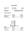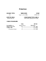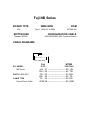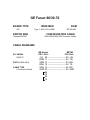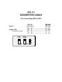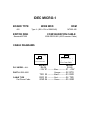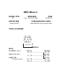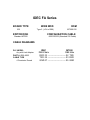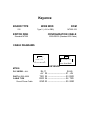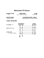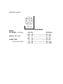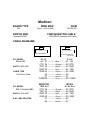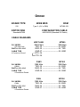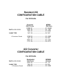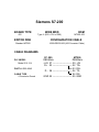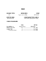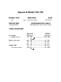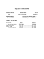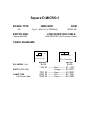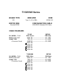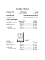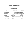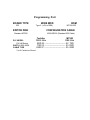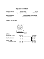
1
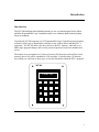
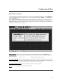
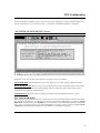
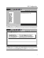
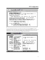
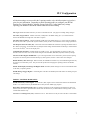
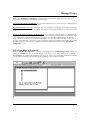
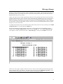
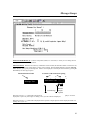
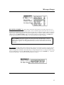
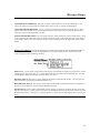
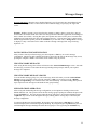
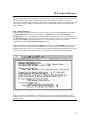
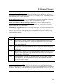
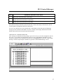
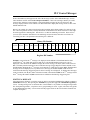
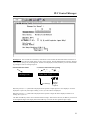
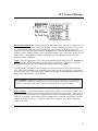
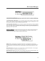
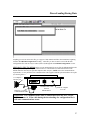
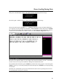
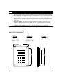
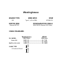
MT-200
INTELLIGENT
MAN-MACHINE
INTERFACE
User Manual
ICP PANEL-TEC, INC.
Post Office Box 2394
Huntsville, Alabama 35801
(256) 534-8132
Warranty & Notices
WARRANTY
ICP PANEL-TEC, INC. warrants that all equipment purchaced hereunder is warranted on a “RETURN TO
FACTORY” basis against all defects in workmanship and materials under normal and proper use and service in its
unmodified condition for a period of one (1) year from the date of initial shipment. ICP PANEL-TEC, INC. sole
obligation under this warranty shall be limited to furnishing parts and labor to remedy such defects; either at the option
of ICP PANEL-TEC, INC. by replacing or repairing any defective parts which are returned to ICP PANEL-TEC, INC.
factory or by making available at a Purchaser designated facility a repaired or replaced part. All replaced equipment
shall become the property of ICP PANEL-TEC, INC. The cost of freight to and from ICP PANEL-TEC, INC. will be
borne by the purchaser. If ICP PANEL-TEC, INC. determines that the equipment returned to it for warranty correction
is not defective, as herein defined, Purchaser shall pay ICP PANEL-TEC, INC. all costs of service, parts, handling, and
transportation.
IMPORTANT NOTICES
By accepting and using the MT200 (s) CONFIGURATION EDITOR SOFTWARE and information proprietary to
ICP PANEL-TEC,INC. USA and / or its Licensers (Licensers), you agree that such software and information
(Software) constitutes valuable trade secrets and propriety information of ICP PANEL-TEC, INC. and/or its Licensers
and that you hold the software in confidence and secrecy and shall not, in whole or part, copy or disclose to any third
party or make any unauthorized use thereof. Authorized use shall be limited to the MT200 (s) upon which the software
is inially supplied. You further agree that this agreement shall insure to the benefit of ICP PANEL-TEC, INC. and any
third party holding any right, title, or interest in the Software, or any software and information from which it is derived,
and their respective transferees, successors, and assigns, and that and subsequent transferee of the unit herin descried
shall be obligated to the same terms of this agreement.
This document is based on information available at the time of its publication. While efforts have been made to render
accuracy to its content, the information contained herein does not purport to cover all details at variations in hardware
or software, nor to provide for every possible contingency in connection with installation, operation, and maintenance.
Features may be descried herin which are not present in all hardware and software systems. ICP PANEL-TEC, INC.
assumes no obligations of notice to holders of this document with respect to changes subsequently made.
ICP PANEL-TEC, INC. makes no representation or warranty expressed, implied, or statuary, with respect to, and
assumes no responsibility for the accuracy, completeness, sufficiency, or usefulness, of the information contained
herin.
In no event shall ICP PANEL-TEC, INC. be responsible or liable for indirect or consequential damages that may result
from installation or use of this equipment.
© 1996 ICP PANEL-TEC, INC.
ALL RIGHTS RESERVED
Post Office Box 2394
Huntsville, AL 35804-2394
PANEL-TEC MT200
i
Table of Contents
Introduction………………………………………………………………………………………..
1
Installing Configuration Software……………………………………………………………….
2
Starting Configuration Software………………………………………………………………..
3
PLC Configuration………………………………………………………………………………
3
Configuring Message Groups
Password Modification…………………………………………………………………..
Disabling Mode Key…………………………………………………………………….
Enabling Alarm Messages……………………………………………………………….
8
8
8
Creating Message Groups
Message Header…………………………………………………………………………
Message Text……………………………………………………………………………
Data Entry Fields……………………………………………………………………….
Data Source……………………………………………………………………………..
Assigning Register Types………………………………………………………………
Assigning Register Numbers…………………………………………………………..
Data Format…………………………………………………………………………….
Display Format…………………………………………………………………………
Range Checking………………………………………………………………………..
Saving Messages and Messages Groups……………………………………………….
8
10
10
11
11
12
12
13
14
14
PLC Control Mode Messages
Message Trigger Register………………………………………………………………
Message Text…………………………………………………………………………..
Data Entry Fields………………………………………………………………………
Data Source…………………………………………………………………………….
Assigning Register Types……………………………………………………………...
Assigning Register Numbers…………………………………………………………..
Data Format…………………………………………………………………………….
Display Format…………………………………………………………………………
Range Checking………………………………………………………………………..
Saving PLC Control Mode Messages………………………………………………….
16
19
19
20
20
21
21
22
23
23
Display/Modify Register Mode………………………………………………………………. .
24
Down-Loading and Saving Data
Saving Configuration to Disk………………………………………………………….
Sending Data to MT200………………………………………………………………
26
27
General Information
MT200 Status Line…………………………………………………………………….
Mode Menu…………………………………………………………………………….
Mounting Dimensions………………………………………………………………….
29
29
30
PANEL-TEC MT200
ii
Introduction
Introduction
The MT-200 Intelligent Man-Machine Interface is low cost unit designed for the Micro
and Mini Programmable Logic Controllers and for use within the harsh industrial (plant
floor) environment.
Currently the MT-200 supports over 25 Programmable Logic Controller protocols and its
software is fairly easy to install and to configure to any of these Micro and Mini PLC’s
supported. The MT-200 allows for direct access to the PLC memory, with little or no
ladder logic program changes and it can be password protected to prevent unauthorized
access.
The display area can support two (2) lines of twenty (20) characters each and has a total
memory store of 64 (can be expanded to 128) messages. It also has three (3) function
keys which you could use to start, stop, or reset the operations within the PLC’s program.
MT200
PANEL-TEC
1
Software Installation
GENERAL INFORMATION
The PANELl-TEC MT-200 Configuration Editor Software Program is designed to operate on an IBM or 100%
compatible computer using MS-DOS 3.3 or higher.
While the Configuration Editor Software Program will run in “WINDOWS”, the user should be aware that the
configuration editor software program will always default to “COM PORT 1” during start-up. This conflict with the
mouse driver program and prevent up/down loading configured programs to the MT-200 interface unit. Should the
user care to operate the program while the “WINDOWS” it is suggested that he or she check the Window Setup for the
mouse driver communication port selection and make any changes as required.
INSTALLATION
Place the supplied program disk into drive “A” (or B).
At the MS-DOS prompt, C:> type in A: (or B) and press the “ENTER” key.
When The “A” prompt appears (or B), A:> type in “INSTALL” and press the “ENTER” key
The following message will appear;
MT200 Configuration Editor Installation Prgram
Enter the Driver where the editor is to be installed⇒
⇒
Enter “C” (or any other hard drive you care to use), then press the “ENTER” key.
A new message will appear;
Enter the subdirectory on drive C to install the editor into ⇒
Suggested directory name is, MT200
The next message to appear before installation is started is;
The Editor will be installed from ‘A:’ to ‘C:\ MT200”.
Is this correct (Y/N) ?
If the above is correct, push the letter “y” key then the “ENTER” key and the software will install itself. The last
message to appear will be;
Is your monitor capable of displaying colors (Y/N) ?
Answer the question, then press the “ENTER” key and the installation is complete.
2
Configuration Editor
SOFTWARE START-UP
To start the MT200 Configuration program, Start your computer, at the MS-DOX prompt; C:> enter cd\MT200> this
command changes the directory you will work with. At the next MS-DOS prompt C:\MT200> Type in MT200 then
press the “ENTER” key.
Upon starting the MT200 software the first screen to appear will be like the one shown below. From this screen, you
can enter any other screen within the software program. By using the cursor’s UP/DOWN keys you can move the
highlighted box between the four system settings. To select the area you wish view or change press the “ENTER” key.
A description of each of the four setting are:
EDITOR SETUP, Allows you to configure the printer and communication ports. Press the “ENTER” key and
another window will appear allowing you to change the printer and/or communication port settings. Configuration
Software defaults are:
Printer = LPT1
Communications to MT200 = COM1
CONFIGURE MT200, Allows you to load configuration data from the driver files and configure the software to your
brand/model of PLC, up load or down load configured (saved) programs. Create the MT200 interface messages groups
and PLC control mode message groups and print all the configured information to a printer.
SUPPORT INFORMASTION, List address and phone numbers for technical support.
QUIT, Exits from the MT200 Configuration Editor Program.
3
PLC Configuration
While in the MT200 Configuration Screen, using your cursor keys, highlight the “Configure MT200” heading anf
press the “ENTER” key or press the letter “C” key. A new screen “Get MT200 Configuration” will appear.
“GET MT200 CONFIGURATION” Screen
Within this screen, there are three screen selections; descriptions of each are as follows;
LOAD DISK FILE, This heading allows you to access and load any one of the currently installed PLC drivers.
READ FROM MT-200, Allows you to access (Up-Load) the current system configuration which is stored within
any MT-200 Interface unit. Allows for making changes within the configuration setup or down-load (copy) the
configuration into another MT-200 Interface unit.
USE DEFAULTS, Resets the software configuration settings to the default (Modicon RTU) PLC setting.
PLC CONFIGURATION
Before configuring the MT200 Interface unit, you must first up-load the system data settings for the brand and model
PLC you wish to interface with. To upload anyone of the files; Make sure the highlighted box is around the “LOAD
DISK FILE” selection and press the “ENTER” key to access the mini-screen which contains all the PLC Data/Setting
files. Using your up/down cursor keys, moving the highlighted box to the PLC setting you want, then by pressing the
“ENTER” key up-load this data information into your computer. (see drawing on next page)
4
PLC Configuration
After the PLC data selection is made, the following screen which you will need to use will automatically appear;
With the highlighted bar around “PLC Configuration” press the” ENTER” key to enter and check the
communications setting within the “MT200 PLC Configuration” screen.
5
PLC Configuration
In case you selected the wrong PLC file, you can make a new selection by pressing the “ENTER” key with the
highlighted bar around the “PLC TYPE” selection, new mini-screen will appear allowing changes to the PLC Type and
default setting as required. (see below drawing) NOTE: Anytime you change the PLC Type setting, any and all
messages that were created using the old setting are completely cleared from memory.
6
PLC Configuration
All function settings are not used for the 3-openings modes, only a brief description is given for is
given for your information. Depending on which operating mode you configure your MT200
Interface for, (Display/Modify), Message Groups or the PLC Control Mode) any settings
requiring your attention is described in detail under that section heading.
PLC Type: Brand and model of the PLC you wish to communicate with. (see page 6 for making setting changes)
PLC Slave (target) Address: Address of the PLC, usually left at the default setting (0 or 1) if communications
between the MT200 and a single PLC is all that is required.
PLC Host (Source) Address: Address of MT200, usually left at the default setting (“0”), some of the GE, Modicon,
PLC Direct, Omron PLC systems will require an address, check your PLC user manual for correct setting requirements.
PLC Response Time Out Value (ms): The amount of time the MT200 will wait after requesting information from a
PLC before trying again. It will make three (3) attempts before ending communications and showing a communication
error on the second (2nd) line of the display area.
Communication Parameters: Default settings are usually correct. It is suggested that you check your PLC user
manual to make sure there were no last minute changes in the Baud Rate, Data Bits, Stop Bits, and Parity Settings.
Password to allow Register Modification: Up to a four digit number can be entered for a password, thus requiring
the operator to enter the password before allowing any data registers, counters or timer values to be changed.
Disable Mode key after Power-Up? When activated, the “MODE FUNCTION” key on the MT200 keypad will only
be active for 6-seconds after power. This prevents the operator from changing the operating mode of the MT200
interface.
Enable Alarm Displays in Message and Register Mode: If enabled, alarm messages can be sent to the MT200 while
in the three (3) operating modes.
MT200 Message Trigger Register: A Data Register of the PLC the MT200 system will monitor for message request
code change.
FOR PLC CONTROL MODE ONLY:
MT200 Function key Status Register: A second PLC (data) register used to communicate between the MT200 and
the PLC. It is written to PLC by the MT200 and is read by the PLC ladder logic program.
Delay Before Turing Function Key Off: The amount of time that can be configured to the function key bits to be
held ON (see above) for a specified amount of time after the function key is released before resetting it OFF. A PLC
Control Mode function only.
Use Line 2 as a Message Line (Y.N): Default is set at no. This function can only be used in the PLC Control Mode.
7
Message Groups
While in the “MT200 PLC Configuration” screen there are some function/data setting which mat require your
attention before configuring any massages groups and messages.
Password to allow Register Modification, Do you require a password? If yes, you can enter up to a 4-digit password
number while this function selection is highlighted.
Disable Mode key after Power-up, if this is to be used, once the MT200 is set to Message Group Mode, it will always
power-up in this Mode after the 6-second time-out. The mode can only be changed during the 6-second power-up time
cycle.
Enable Alarm Displays in Message and Register Mode, If you wish to have alarm messages te be displayed on the
MT200, answer “Y” for yes, of not leave at default setting. If you answered yes to this setting, you will need to assign
a data register number to the MT200 Message Trigger Register. Not only will you need to create your “Message
Groups” but also you will need to create the Alarm Messages in the “PLC Control Mode Message” screens. Refer to
the “PLC Control Messages” section after you have completed all required group headings and messages. By pressing
the “F10” function key, saves the PLC Configuration information and the software will open the “Edit MT200
Configuration” screen.
CREATING MESSAGE GROUPS
From the ”Edit MT200 Configuration” screen, move the highlighted bar to “MT200 Message Group” heading and
pressing the “ENTER” key opens the “MT200 Message Group Header” screen. In this screen you create “Message
Group Header”, up to eight (8) Group Headings and each group can have up to 20 messages (remember, the MT200
can only support 64 messages total) and Message Group Heading s does not count as messages.
8
Message Groups
Messages you create within the groups may contain a combination of text and data. The data could be the contents of a
data (storage) register, a preset value of a counter or timer and you define of the operator can enter values from the
MT200 keypad or only view its contents.
Usually, there will be no PLC Ladder Programming required to use this operating mode unless you have selected the
“Displayed Alarm Messages” option, which will require some ladder logic programming (see PLC Control section) to
display these alarms. If this option is not used, you can take any current ladder logic program and create Message
Group (s) and messages within these groups to allow an operator access to selected data registers, counters, and timers
of your choosing. The type of data register, counter or timer to be accessed is individually defined within each group
message as you create each of them.
An example of the Message Groups with sample messages within each group can be seen by returning to the “MT200
Configuration Files” screen and loading the “DEMO” file.
With the highlighted bar at the first message group heading, enter in your “Message Group Heading”. For test
example, type in “START-UP MESSAGE” and then press the “ENTER” key. A new “Select MT200 Message”
screen appears, in which you will select the first ** Unused Message ** and press the “ENTER” one more time.
Another new screen (page 10) appears, within this screen you create (or edit) the message text and data (digit) field
required to display values or for data entry. Each of the entry points shown on the “MT200 Message Entry” screen
drawing are listed as they appear on the screen with its function and complete description.
9
Message Groups
MESSAGE FOR GROUP (#) : Lists the Group Name (header) of r a reference, to insure you are creating this new
message under the correct message header.
MESSAGE TEXT: This field can contain any combination of text and data, the maximum number of characters is 20,
this includes many data entry fields (digits) you may want to include. With the highlighted bar around the “Message
Text” selection, just type in your message text. If data is to be displayed or entered you enter the fields by pressing the
F3 or F4 keys for each digit required.
Function/Selection Label
#’s shown to aid in character spacing
1
10
20
⊥. . . . ⊥ . . . . ⊥. . . . ⊥ . . . . .⊥
Message Text:
Enter Prod. CNT ^^^^
Text Message
Number
of digits
required
F3, when pressed, a “^” symbol will be displayed which represents a single digit that is to be displayed. It will be
displayed as a space only if this digit is a leading “zero” (0) in the value to be displayed.
F4, when pressed, a “~” symbol will be displayed which represents a single digit that will be displayed whether it is
leading “zero” (0) or not.
10
Message Groups
The “F3” and “F4” key entries can be combined within a message. When used in this case, the “F3” key is most often
used for the most significant digits of the display field and the “F4” key is used for the least significant digit or digits.
NOTE: The data field should be defined with enough digits to hold the largest value that will
ever be displayed in it. Should you define without enough digit spaces only the least significant
digits of the value will be displayed.
DATA SOURCE: This specifies where to obtain the data to be displayed within the message. Move the highlighted
bar down to the “Data Source” selection and press the “ENTER” key., a mini screen will appear allowing you to
select one of the following choices for the data sources;
KEYPAD ENTRY ONLY, When the message is first displayed, the data field will be initialized to 0. When a value is
entered by the operator on the MT200 numeric keypad, it will be written ti the PLC when the “ENTER” key (MT200
keypad) is pressed. This entered value is written to the PLC’s register specified by your entry in the “Register Type”
and “Register Number” fields, described a little later in this section. When the message has been written to the PLC a
“Data Written” message will appear o the bottom line of the display area.
PLC REGISTER DISPLAY ONLY, When this message is first displayed it will read the specified PLC register and
its contents will be displayed in the data field. As long as the message remains in the display, the data field will be
displayed in the data field. As long as the message remains in the display, the data field will be continually updated
with the current value from the PLC’s register, counter or timer. No data is written tot eh PLC when using this data
source; it can only display the contents of the PLC register.
PLC REGISER DISPLAY & KEYPAD ENTRY, When the message is first displayed, the specified PLC register
will be read and its current contents will be displayed. The PLC register will be continually read and its contents
displayed until the operator starts entering new data, either by pressing the “CLEAR” key or by pressing one of the
numeric keys on the MT200 keypad. During this time, only the data entered via the MT200 keypad will be displayed.
Once the “ENTER” key has been pressed, the new data will be written to the specified register, counter or timer in the
PLC. The MT200 will return to continually monitoring the specified PLC register and updating the data field.
REGISTER TYPE, The register type specifies which PLC register area to read the data field value from and write
the keypad entered value to. To change the register type, press the “ENTER” key while the highlighted bar is around
the “Register Type” selection. A smaller window will appear, listing the choices (data registers, counter preset or
current value, timer preset or current value, etc.) Which are different for each brand and model of PLC. Check PLC
user manual for correct configuration name or type.
11
Message Groups
REGISTER NUMBER, The register number specifies the offset (address) into the PLC register area, as it
would be referenced in the PLC’s ladder logic program. The first available register will be either zero (0) or one (1),
depending on the addressing of your particular type of PLC being used. To change the register number, just enter the
register number while the highlighted bar is around the “Register Number” selection. Should you enter a combined
“Register Type” and “Register Number” that is out of range (invalid) for your particular PLC, a “Config Error”
message will be displayed on the MT200 display area when that particular message is displayed.
BIT NUMBER, This field will appear only with concern PLC (brand) settings. Used to
configure to a brand fof PLC addressing requirements to work with the inputs, internal and
output address registers. See the application note for your PLC to determine how to use the
bit number.
Data Format, The data format specifies whether the PLC register to be read from or written to si single precision
(one data register) or double precision (two consecutive data registers). Two types of formats for double precision
registers are supported by the MT200. The default setting is Unsigned Single Precision. Toe change the format setting,
move the highlighted bar around the “Data Format” selection and press the computers “ENTER” key. A selection
(window) box will appear. Your choices for the Data Format are as follows;
12
Message Groups
UNSIGNED SINGLE PRECISION, Only one (1) register will be read from or written to within the PLC. This
register will contain an unsigned with the possible values of (0 to 65,535) or (0 to ffff) for hexadecimal.
UNSIGNED DOUBLE PRECISION. Two (2) consecutive registers will be read from or written the PLC. These
registers will contain a normal 32-bit word with the first register containing the low order data and the next higher
consecutive register containing the high order data.
8-DIGIT DOUBLE PRECISION, Two (2) consecutive registers will be read from or written to within the PLC. Each
of these registers will contain values from (0 to 9999) with the first register containing the low order four (4) digits of
(of the 8-digits number) and the next higher consecutive register containing the four (4) higher digits of the 8-digits
number.
DISPLAY FORMAT, This format determines how the data will be displayed within the MT200 data field. To
change, press the “ENTER” key while the highlighted bar is around the “Display Format” selection and a small
window will appear with the following selections;
DISPLAY AS ‘*’s, This option is used primarily under the PLC Control Mode for keypad entry of passwords. Instead
of displaying the numeric key value, an ‘*’ will be displayed for each digit entered on the MT200 keypad. The value
entered will be a number in which only the number keys 0-9 are used.
DECIMAL (Base 10), This option is used to displayed data fields as normal decimal numbers. The only digits that
will be displayed or accepted from the MT200 keypad are 0-9.
HEXADECIMAL (Base 16), This option is used to display the data fields as hexadecimal numbers. The digits A-F as
well as 0-9 can be displayed or entered from the MT200 interface unit.
BINARY (Base 2), Used to display the data fields as binary numbers, in which only the digits “0” and “1” are used.
Normal 16-bit registers (i.e. Data, Counters, and Timers) can be displayed in binary, but may not be written to from the
MT200 keypad in binary. Only discrete or single-bit registers (i.e. Inputs, Internals, and Outputs) may be entered in the
binary.
13
Message Groups
RANGE CHECKING, When the range checking function is used for operator entry, the MT200 will not
write the entered keypad value to a PLC unless if falls within the range you specify by the Upper and
Lower.
Example: Within a program, you need to allow the operator to change a timer’s preset value. But you
need to make sure he/she cannot enter a time out value greater that 5-minutes (upper limit) and nothing less
than 1-minute (lower limit). In using this option, the operator must enter a (timer preset) value that falls
within these two limits before the value can be written to the PLC. If an incorrect value is entered on the
MT200 keypad and the operator pressed the “ENTER” key to enter this value, a “Range Error” message
is displayed. Only “valid” data can be written to the PLC through a message with “range Checking”
Option set on.
SAVING MESSAGE MCONFIGURATION
After you have created your first message, press the computer’s “F10” key to save this message
configuration. Should you make a mistake and wish to cancel all work done on the message entry screen,
pressing the computer’s “ESC” will exit this screen without saving any entries.
CREATING MORE MESSAGES
After saving the last message, the software will return to the “Select MT200 Message” screen. Select the
next message you wish to create under this message heading and repeat steps until all your required
messages are completed.
CREATING MORE MESSAGE GROUPS
To create another message group, save your last message, which will return you to the “Select MT200
Message” screen. From this screen, press the computer’s “ESC” key to return you to the “MT200
Message Group Heading” screen and select the next unused heading. Create the heading and repeat all
steps required for each message needed under the new group heading.
MESSAGE GROUP OPERATION
After saving and downloading the message configuration (see Saving/Down-Loading section) to the
MT200 Interface unit. The operator selects the first message group requiring his attention and presses the
keypad “ENTER” key. The first message under this group will appear. By using the MT200 keypad’s
“Up/Down” keys. He can scroll through all messages, entering data or viewing only as allowed by the
message configuration.
To return to the Message Group Headings, the operator presses the keypad’s “ESCAPE” key, which
returns and displays the current Message Group Heading. By using the keypad “Up/Down” Keys he can
scroll through the message Headings and select the next group to view by pressing the “ENTER” key.
14
PLC Control Messages
The PLC Control Mode allows you to define up to 64 messages, which can be displayed in any order on the
MT200 Interface Unit by the PLC’s ladder logic program. These messages, like those create in the
“Messages Group Mode” made contain any combination of text and data. Remember, the MT200 can store
a total of 64 messages; regardless of whether they are PLC Control Mode messages or Message Group
Mode messages.
PLC Control Messages
With the MT200 Configuration Software is in the very first screen, move the highlighted bar around the
“Configure MT200” selection. Press the computer’s “ENTER” key to open the “Get MT200
Configuration” screen. The highlighted bar should default around the “Load Disk File” selection, press
the “ENTER” key again and by using the cursor up/down keys select the PLC driver of your choosing and
pressing the “ENTER” key up-loads the PLC driver. After selecting your driver the software
automatically opens the “Edit MT200 Configuration” screen.
With the highlighted bar around “PLC Configuration” selection, press the “ENTER” key. While you are
in this screen, (see below) you will need to configure some of these setting to your requirements. The
default setting for PLC Type, PLC slave, Host Time Out Value and Communication Parameters are usually
correct, but it is suggested you check your PLC’s user manual for any possible, last minute changes.
While you are still in the “Mt200 PLC Configuration” screen there are function/data setting you must
configure if the system is to work correctly. A complete description of these function/data settings begin
on the next page.
15
PLC Control Messages
Password to allow Register Modification, Do you require a password? If yes, you can enter up to a
4-digit password number while the highlighted bar is around this selection. The operator will require to
enter this password from the MT200 keypad, before he or she can modify any data. Without the password
ne or she can only view messages or data values.
Disable Mode Key after Power-Up? If used, the MT200 will always power-up in the last mode selected.
The mode setting can only be changed during the first 6-seconds after power is applied.
Enable Alarm Displays in Message and Register Mode? Used if you want Alarm Messages to be
displayed in the Message Group or Display/Modify Register Modes only. This function is completely
ignored by the system in PLC Control Mode.
MT200 Message Trigger Register, Here you will assign a data register, which the MT200 Interface Unit
will monitor for message (binary) number changes. Some ladder logic programming is required, to allow
the PLC to load a new binary number into this data register each time a new message or alarm is to be
displayed. Only certain bits of this trigger register are used for message display, see the chart below for
each bit used and its function.
Bit #
16
15
9
8-1
NAME and CONTROL FUNCTION of BIT
DISPLAY MESSAGE BIT
This flag (bit) is set (ON) by the ladder program to signal the MT200 that a message is to be
displayed. The message number to be displayed must be written to bits 8-1 before aor at the
same time bit 16 is set ON. Bit 16 will be reset (OFF) by the MT200 when the requested
message has been displayed.
NUMERIC KEYPAD VALUE WRITTEN
This flag (bit) is et (ON) by the MT200 when a numeric keypad value entered by the operator
has been written to the PLC. It is reset (OFF) by the PLC program after the entered value has
been processed.
DISPLAY MESSAGE ON 2ND LINE BIT
This flag (bit) is set (ON) at the same time bit 16 and message number (bits 8-1) are set (ON)
by the PLC ladder logic program to signal the MT200 that this message is to be displayed on
the 2ND line instead of the first line.
MESSAGE NUMBER TO DISPLAY
The message number is set by the PLC’s program before (or same time) setting the display
message flag (bit 16). The message number is assigned by the configuration editor when the
message is created. The message number is only read by the MT200 when bit 16 is set (ON),
so it does not need to be cleared.
MT200 Function key Status Register, This is a second data register you will assign and it must be a
different data register number than the one used for the messages trigger register. When the operator
pushes any of the Function keys on the MT200 keypad, a bit will turn ON momentarily (see default turn off
time delay). Within the PLC’s ladder program this bit could be monitored to allow a process to start, stop
or reset all count values within the ladder program. See chart (next page) for Function Key bit operation.
16
PLC Control Messages
Bit #
NAME & CONTROL FUNCTION
1
Reflects the on/off status of Function Key “F1”. Set to 1 (ON) when depressed and cleared to 0
(OFF) when released and after set time delay.
Reflects the ON/OFF status of Function Key “F2”. Set to 1 (ON) when depressed and cleared to
0(OFF) when released and after seer time delay.
Reflects the ON/OFF status of Function Key “F3”. Set to 1 (ON) when depressed and cleared to
0(OFF) when released and after set time delay.
2
3
Delay Before Turning Function Key OFF, Default value is 100 ms time delay to allow the PLC time to
scan and update its program that this bit has turned ON.
Use Line 2 as a Message Line (Y/N), With the PLC Control Mode you have the option of displaying
messages on the second line of the mt200. This line is usually used to display information about the
MT200 status (described in the System Operational Section).
CREATING PLC CONTROL MESSAGES
After entering your data/function setting changes, press the “F10” key to save this configuration and exit
this screen. Your computer will automatically return you to the “Edit MT200 Configuration” screen.
Using your computer’s cursor Up/Down arrow keys move the highlighted bar to the “PLC Control Mode
Message” selection and pressing the “ENTER” key opens the “Select MT200 Message” screen.
17
PLC Control Messages
Notices the numbers(s) that appear to the left of the messages (in the “Select MT200 Message” screen).
These numbers could be called “Call or Request Numbers”. This is the (message) number you would
enter into the “Message Trigger Register” along with (display message bit) bit #16 ON to have this
message displayed on line #1 or with bits #16 and 9 both ON to display this message on the #2 line of the
MT200 Interface Unit.
Below is an example of a data register showing the bit number and its binary number for each one of the
bits. These bit positions shown, is strictly the manner in which Panel-Tec labels and refers to each single
bit with a typical PLC Data Register. Not all PLC’s use this bit numbering convention. Please refer to
your user (PLC manual to determine it’s bit numbering convention and use this table as reference for
converting your PLC’s bit positions to this drawing if it is different.
Binary Bit Number
32,768
16,384
8,192
4,096
2,048
1,024
512
256
128
64
32
16
8
4
2
1
16
15
14
13
12
11
10
9
8
7
6
5
4
3
2
1
Register Bit Number
Example, You wish for the 7TH message to be displayed on the MT200. This MT200 Interface Unit
requires the 16Th bit of this data register be ON (bit 16, tells the MT200 that a message is to be on
displayed). This means for the MT200 to display the correct message, bits 16, 3, 2, and 1 will need to be
ON. The binary number needed to be moved into this message Trigger Register would be 32,775. After
the MT200 has displayed this (7TH) message, it will turn bit 16 of this trigger register OFF. Should another
message need to be displayed, let’s say the next (8TH) message, the number 32,776 would need to be
entered into this Message Trigger Register for the 8TH message to be displayed. To display these messages
in the second line, bits 16, 9, 3, and 1 will need to be ON, or the number 33,031 for the 7TH message and for
the 8Th message the number 33,032 would need to be loaded into the Message Trigger Register.
EDITING A MESSAGE
Select the message (number) you wish to create (or edit) by moving the highlighted bar with the computer’s
UP/DOWN arrow keys, then pressing the “ENTER” key opens (next page) the “MT200 Message Entry”
screen. Creating messages for use under the PLC Control Mode is very similar to creating messages under
the “Group Messages Mode”, except there are no group headings to create. Again, each of the entry points
on the “Mt200 Message Entry” screen are listed as they appear on the on the screen with its function and
complete description.
18
PLC Control Messages
Message Text: This text field can conclude any combination of text and data, the maximum number of characters is
20, this includes any data entry fields (digits) you may want to include. With the highlighted bar around the “Message
Text” selection, just type in your message text. If data is to be displayed (viewed) or entered, you can enter the fields
by pressing F3 or F4 for each digit required.
Function/Selection Label
#’s shown to aid in character spacing
1
Message Text:
10
20
⊥....⊥....⊥....⊥....⊥
Enter Prod. CNT ^^^^
Text Message
Number
of digits
required
F3, when pressed, a “^” symbol will be displayed which represents a single digit that is to be displayed. It will be
displayed as a space only if this digit is leading a “zero” (0) in the value to be displayed.
F4, when pressed, a “~” symbol will be displayed which represents a single that will be displayed whether it is a
leading “zero” (0) or not.
The “F3” and “F4” key entries can be combined within a message. When used in this case, the “F3” key is most used
for the significant digits of the display field and the “F4” key is used for the least significant digit or digits.
19
PLC Control Messages
NOTE: The data field should be defined with enough digits to hold the largest value that will ever be displayed
on it. Should you define a field without enough digit spaces only the least significant digits of the value will be
displayed.
DATA SOURCE: This specifies where to obtain the data to be displayed within the message Move the
highlighted bar down to the “Data Source” selection and press the ”ENTER” key, a mini screen will appear
allowing you to select one of the following choices for the data source;
KETPAD ENTRY ONLY,. When the message is first displayed, the data field will be initialized to 0.
When a value is entered by the operator on the MT200 numeric keypad, it5 will be written (sent) to the
PLC when the “ENTER” key (MT200 keypad) is pressed. This entered value is written to the PLC’s
register specified by your entry in the “Register Type” and “Register Number” fields, described a little later
in this section. When the message has been written to the PLC a “data Written” message will appear on the
bottom line of the display area.
PLC REGISTER DISPLAY ONLY, When this message is first displayed it will first read the specified
PLC register and its contents will be displayed in the data field. As long as the message remains in the
display, the data field will be continually updated with the current value from the PLC’s register, counter,
or timer. No data is written to the PLC when using this data source, it can only display the contents of the
PLC register.
PLC REGISTER DISPLAY & KEYPAD ENTRY, When the message is first displayed, the specified
PLC register will be read and its current contents will be displayed. The PLC register will be continually
read and its contents displayed until the operator starts entering new data, either by processing the
“CLEAR” key or by pressing one of the numeric keys on the MT200 keypad. During this time, only the
data entered via the MT200 keypad will be displayed. Once the “ENTER” key has been pressed, the new
data will be written to the specified register, counter, or timer in the PLC. The Mt200 will return to
continually monitoring the specified PLC register and updating the data field.
REGISTER TYPE, The register type specifies which PLC register area to read the data field value
from and write the keypad entered value to. To change the register type, press the “ENTER” key while the
highlighted bar is around the “Register Type” selection. A smaller window will appear, listing the choices
(data register, counter preset, or current value, timer preset, or current value, ect.), which are different for
each brand and model of OLC. Check your PLC user manual for correct configuration name or type.
20
PLC Control Messages
REGISTER NUMBER, The register number specifies the offset (address) into the PLC register area as it
would be referenced in the PLC’s ladder logic program. The first available register will be zero (0) or one
(1), depending on the addressing of your particular type of PLC being used. To change the register
number, just enter the register number while the highlighted bar is around the “Register Number” selection.
Should you enter a combined “Register Type” and “Register Number” that is out of range (invalid) for your
particular PLC, a “Config Error” message will be displayed on the MT200 display area when that
particular message is displayed.
NOTE: When the operator enters a new value on the MT200 keypad and then presses the “ENTER” key
on the keypad, the 15TH bit of the Message Trigger Register is turned ON. After the PLC (CPU) has
processed and stored this data, it will turn Message Trigger Register bit #15, OFF.
You may consider using this 15TH bit as an input to an Up-Counter’s pulse line to count each operator
entry. Then create some ladder logic programming steps that could enter a new message request number
for each count (of the counter) into the trigger register, thus stepping an operator through a machine set-up
before allowing the operator to start the machine.
BIT NUMBER, This field will appear only with certain PLC (brand) settings. Used to configure
to a brand of PLC addressing requirements to work with the inputs, internal and output address
registers. See the application note for your PLC to determine how to use the bit number.
DATA FORMAT, The data format specifies whether the PLC register to be read from or written to is a
single precision (one data register) or a double precision (two consecutive data registers). Two types of
formats for double precision registers are supported by the NT200. The default setting is Unsigned Single
Precision. To change the format setting, move the highlighted a bar around the “Data Format” selection
and press the computers enter key. A selection (window) box will appear. Your choices for the Data
Format are as follow;
21
PLC Control Messages
UNSIGNED SINGLE PRECISION, Only one (1) register will be read from or written to within the PLC.
This register will contain an unsigned with possible values of (0 to 65,535) or (0 to FFFF) for hexadecimal.
UNSIGNED DOUBLE PRECISION, Two (2) consecutive registers will be read from or written to within
the PLC. These registers will contain a normal 32-bit word with the first register containing the low order
data and the next consecutive register containing the high order data.
8-DIGIT DOUBLE PRECISION, Two (2) consecutive registers will be read from or written to within the
PLC. Each of these registers will contain values from (0 to 9999) with the first register containing the low
order four (4) digits (of the 8-digit number) and the next higher consecutive register containing the four (4)
higher digits of the 8-digit number.
DISPLAY FORMAT, This format determines how the data will be displayed within the MT200 data
field. To change, press the “ENTER” key while the highlighted bar is around the “Display Format”
selection and a small window will appear with the flowing selections;
DISPLAY AS ‘*’s, This option is used primarily under the PLC Control Mode for keypad entry of
passwords. Instead of displaying the numeric key value, and*’ will be displayed for each digit entered on
the MT200 keypad. The value entered will be a decimal number in which only the number keys 0-9 are
used.
DECIAML (Base 10), This option is used to display fields as normal decimal numbers. The only digits
that will be displayed or accepted from the MT200 keypad are 0-9.
HEXADECIMAL (Base 16), This option is used to display the data fields as hexadecimal numbers. The
digit A-F well as 0-9 can be displayed or entered from the MT200 interface unit.
22
PLC Control Messages
BINARY (Base 2), Used to display the data fields as binary numbers, which only the digits “0” and “1”
are used. Normal 16-bir registers (i.e. Data, Counters, and Timers) can be displayed in binary, but may not
be written to form the MT200 keypad in binary. Only discrete or single-bit type registers (i.e. Inputs,
Internals, and Outputs) may be entered in binary.
RANGE CHECKING, When the range checking function is used for operator entry, the MT200 will not
write the entered keypad value to a PLC unless if falls within the range you specify by the Upper and
Lower limits.
EXAMPLE: Within a program, you need to allow the operator to change a timer’s preset value. But, you need to
make sure he/she cannot enter a time out value greater than 5-minutes (upper limit) and nothing less than 1-minute
(lower limit). In using this option, the operator must enter a (timer preset) value that falls within these two limits
before the value can be written to the PLC. If an incorrect value is entered on the MT200 keypad and the operator
presses the “ENTER” key to enter this value, a “Range Error” message is displayed. Only “valid” data can be
written to the PLC through a message with “Range Checking” option set on.
SAVING MESSAGE CONFIGURATION
After creating your first message, press the computer’s “F10” key to save this message configuration. If
you make a mistake, or wish to cancel and not save this message configuration, pressing the “Esc” key will
exit this screen without saving any entries and return you to the “Select MT200 Message” screen.
CREATING MORE MESSAGES
Pressing the “F10” key save your last message and returns you to the “Select MT200 Message” screen.
Move the highlighted bar to the next message to create and repeat the instructions for this message. While
tin the “Select MT200 Message” screen and by using the Page UP/DOWN keys you can move all 64
messages.
PLC CONTROL MODE OPERATION
After saving and downloading these messages configurations (see Saving DownLoading section) tot the
MT200 Interface unit and power up the PLC and MT200 unit, the PLC’s ladder logic program enters the
message first request number into the Message Trigger Register, which displays that message. With the
PLC scanning it’s logic program it sees events accrue. An input turns ON or OFF, a temperature set point
goes High or Low, or preset count is reached. The PLC can load a new message trigger request number
into the Message Trigger Register and the MT200 displays a message per that number request to the
operator for his or her action, based on these events.
23
Display/Modify Register Mode
The Display/Modify Register Mode provides the user access to the PLC data registers, timers, counters, or
input and output I/O addresses. The MT200 Interface unit can be used with the Display/Modify Register
Mode as its only operating mode where no programming of the PLC or configuring of the MT200 is
required. Only the default disk file for your PLC brand and model (from the “Get PLC Configuration”
screen see Message Groups or PLC Control Mode for up-loading information) needs to be downloaded into
the MT200 for this mode to operate.
Normally the Display/Modify Register Mode is used by the maintenance crew for trouble shooting the
PLC’s I/O’s or changes in set points, counter and timer preset values during a start up or trouble shooting
of the system.
Thsis Display/Modify Mode is also an active port of the Message group and PLC Control Modes and can
be accessed by holding down the keypad’s “MODE” key for 2-seconds. If te user has enabled the “disable
Mode Key after Power-Up” option, then this operating mode can only be accessed during the first
60seconds after the MT200 is powered up. After pressing the “MODE” key, the MT200 operating system
changes and your display should look like the below drawing.
MT200
1) Disp/Modify Regs
UP, DN, ENTER
Pressing the keypad’s “ENTER” key allows you to enter this mode. Using the keypad’s “Up/Down”
arrow keys, you can scroll through the list of available PLC register types, until the desired register is
displayed. Then press the “ENTER” key, enter in the desired register number and press the “ENTER”
key again and its current contents will be displayed.
To select a different register, press the keypad’s “ESCAPE” key once to return to the “Register Number”
prompt and enter I enter new desired register number then press the “ENTER” key to view the new
register’s current contents.
To select a different register type, press the “ESCAPE” key twice to return you to “Register Type” list.
Again by using the keypad’s “Up/Down” arrow keys, select the new type of register you wish to view and
press the “ENTER” key. Enter in the new register number you wish to view and then press the keypad’s
“ENTER” key to view its contents.
If the contents of the registers being displayed can be changed, a “W” along with another letter (see below
list) will appear in the status (2ND) line. The method by which new data can be entered depends on the data
format, as follows;
24
DOWN-LOADING /SAVING DATA
BINARY (a “B” is depending on the 2ND line). Each point or contact is set or cleared
individually. To select an individual point, press the “SHIFT” key (a “^” appears in the 2ND line)
and by using the Left/Right arrow keys to select each point, the selected point is under lined.
Pressing the “!” key sets the point (contact) ON and the “CLEAR” key resets it OFF.
DECIMAL (a “D” is displayed on 2ND line). In the decimal format, the entry of a new value or
pressing the “CLEAR” key clears the old value. After entering the new value, press the “ENTER”
key to write this value into the PLC. After the value is successfully written, a “Data Written” will
appear on the status (2ND) line for about one(1) second.
NOTE: When using the numeric (0-9) keys, the MT200 keypad must be in the “Shift” state. If the “^”
appears anywhere in the status (2ND) line, press the “SHIFT” key to clear this state before keying in a decimal
number.
HEXADECIMAL (a “H” is displayed on 2ND line). In the hexadecimal format, the entry of a
new value is begun by pressing the “CLEAR” key or by entering the first digit of the new value,
which clears the old displayed value. After entering in the new value on the keypad, pressing the
“ENTER” key writes this value to the PLC. Once the data has been successfully written, the
message “Data Written” will appear on the stauts (2ND) line for about one (1) second.
NOTE: When entering in the hexadecimal format, the “A-F” key may be used in addition to the
numeric (9-0) keys to enter a value. To enter a digit that may be “A-F”, the MT200 keypad must
be in the “SHIFT” state, remembering when entering the numeric (9-0) digits the MT200 must be
out of the “Shift” state. Whenever the “^” appears on the status (2ND) line you are in the shift state.
25
Down-Loading/Saving Data
After you have created all the desired messages, pressing the “F10” key will save the last configured
message. Pressing the “F10” key again saves the screen (configuration) and backs the software up by one
screen. Keep pressing the “F10” key until the software has returned you to the “Edit MT200
Configuration” screen. Once at this screen, pressing the computer’s “Esc” key will open the next screen
you will use, the “Save MT200 Configuration” screen.
Within the “Save MT200 Configuration” screen you can choose to save your configured messages to a disk
file, or just download the configured message data to the MT200 Interface unit. It is recommended that
you first save your configured message data to a disk file and after saving this data, then send this
configured data to the MT200 Interface unit.
It is easier to loads (retrieve) a saved message disk file from the “Get MT200 Configuration” screen, than
trying to up-load the configuration data from a MT200 Interface unit that is on a machine currently in use.
Once this file has been loaded or retrieved, you can edit some of all of the message configurations, create
another file and save it under file name or simply down-load this configured data file another MT200
should the need arise.
SAVING CONFIGURATION TO DISK,
Place the highlighted bar around the “Save to Disk” selection and press the “ENTER” key. A new screen
appears in which you type in the files name and then pressing the “ENTER” key saves this file under the
name you just entered.
26
Down-Loading/Saving Data
Anything you need to retrieve this file, go to page 4 of this manual and follow the instructions beginning
with the “Get MT200 Configuration” heading. A data file you have created is saved with the PLC
Configuration files and can only be loaded (retrieved) through the “Get MT200 Configuration” screen.
SEND DATA FILE TO MT200, Before you can transmit this file or any file, the MT200 Interface unit
must be powered (AC power adapter) and the Panel-Tec communications cable hooked between the
MT200 Interface unit and your personal computer’s RS-232 port. NOTE: Due to the communications
requirements, use only the Panel-Tec communications cable supplied with the optional Software Set-up kit
(see drawing below).
To computer’s
RS-232 port
Panel-Tec’s Config.
Communication Cable
Communication Cable
between
MT200 & PLC
From AC Adapter
9-12 vde
WARNING: If a communications cable is connected between the PLC can the
MT200, remove it. If the cable during the downloading of a configuration file, it
will cause communications errors.
27
Down-Loading/Saving Data
With power to the MT200, the display of the MT200 should be displaying the first message;
1) Disp/Modify Regs
UP, DN, ENTER
Press the keypad’s “DOWN” arrow key, until you have reached the fourth message;
4) Send/Recv Config
UP, DN, ENTER
Then pressing the keypad’s “ENTER” key, a “Waiting for PC Host” message will appear Returning to
your computer, move the highlighted bar around the “Send to MT200” selection and press the “ENTER”
key to start the downloading of the configuration data. A screen like the one below will appear. After all
16 blocks have been transmitted the software returns to the “Save MT200 Configuration” screen.
Disconnect your computers and the AC power adapter and connect the MT200 to your PLC. The MT200
(in most cases) receives its power from the PLC through the communications cable.
Press and hold (20seconds) the keypad’s “MODE” key until the first message appears. Press the keypad’s
“DOWN” arrow key, to select the operating mode desired then press the “ENTER” key to begin operating
selected mode.
Should the PLC and MT200 be powered off, the MT200 will return to the last operating mode selected it
was operating under when power is returned.
28
MT200 STATUS LINE
The bottom line of the MT200 display is used as a status line. The first 12 characters on the status line will
provide the user/operator with information about where you are or what keystrokes are valid at this current
time. The remaining positions may containing any of the following:
W (Write) A data field is present in the message on the top line which can be changed or written
to from the MT200 Interface keypad.
R (Read) A data field is present in the message on the top line that is a “READ ONLY” message.
The data within this field can not be changed from the MT200 Interface keypad.
D (Decimal) A data field is present in the message on the top line in which its contents are
displayed and/or can be entered as normal decimal (Base 10) number (s).
H (Hexadecimal) A data field is present in the message on the top line in which its contents are
displayed and/or can be entered in hexadecimal (Base 16).
B (Binary) A data field is present in the message on the top line in which its contents are displayed
and/or entered in binary (Base 2).
OK (PLC Communication Status) The PLC and MT200 are communicating when the “OK” is
displayed.
^ (Shift State) The MT200 is currently in the shift state. The shifted state allows the use or
function of the upper portion of the keypad keys.
MODE MENU
The mode menu is used to select the operating mode of the MT200 as well as configuration and diagnostics
functions. To select an option, use the “Up/Down” arrow keys to scroll through the menu until the desired
option is displayed then press the “ENTER” key to enter this option. With the exception of the “Set PLC
Address” and “Display Version”, once the mode is selected, the MT200 will remain in that mode, even
when power is removed and re-applied. To change modes, hold the “MODE” key down for 2-seconds.
The Mode Menu contains the following;
1) Display/Modify Registers, This option will place the MT200 into the Display/Modify
Registers mode (see Display/Modify Register Mode Heading for complete description).
2) Message Groups, This option will place the MT200 into the Message Groups mode (see
Message Group heading for complete description).
3) PLC Control Mode, This option will place the MT200 into the PLC Control Mode (see PLC
Control Messages heading for complete description).
4) Send/Receive Configuration, Once this option is selected, the MT200 will enter this mode
each time power is applied. (see Down-Loading /Saving Data heading for complete
Description)
5) Keypad Diagnostics, The MT200 will display a “Press Keys” message. Each time a key is
pressed, the name of the key will be displayed. Used to test the MT200 keypad and display.
6) Port Diagnostic, The MT200 will display “Port Diagnostics” message on the top line and a
“Pass” or “Fail” on the second line. The diagnostics test will only pass if a loop-back is
placed on the DB-9 connector at eh bottom of the MT200. Refer to the application note for
your PLC (supplied with the manual) to determine which connections are required for this
loop-back.
7) Set PLC Address, This option is provided so that the PLC address (if required) can be
changed without having top use the Mt200. Refer to the application note for your PLC
(supplied with the manual) to determine if the PLC address needs to be changed.
8) Display Version, Displays the version of the MT200 firmware for 4-seconds only.
MOUNTING DIMENSIONS
With Bezel
Width: 6.12”
Height: 7.89”
Depth: 1.400”
MT200
Width: 5”
Height: 6.5”
Depth: 1.339”
Cut Out
Width: 5.12”
Height: 6.89”
6.12”
5.62”
MT200
7.39”
7.89”
A-B SLC500
BOARD TYPE
WIRE MOD
232
Type 3 (+12V to DB9)
EDITOR DISK
ROM
MT200-SLC
CONFIGURATION CABLE
MT200-SLC
6000-RS232 (Standard 232 Cable)
CABLE DIAGRAMS
SLC500
MT200
DB9 Female
DB9 Male
RXD 02 ------------------------------ 02 TXD
TXD 03 ------------------------------ 03 RXD
GND 05 ------------------------------ 05 GND
PLC MODEL - 5/03 & 5/04
PART # 6000-6002
CABLE TYPE
4 Conductor Round
8
7
5
6
4
2
3
1
Solder End
MicroLogix
MT200
PLC MODEL - MicroLogix
PART # 6000-6003
CABLE TYPE
4 Conductor Round
Mini Din
DB9 Male
+24V 01 ------------------------------ 09 +24V
RXD 04 ------------------------------ 02 TXD
TXD 07 ------------------------------ 03 RXD
GND 02 ------------------------------ 05 GND
Entertron
BOARD TYPE
232
WIRE MOD
Type 2 (+5V to DB9)
ROM
MT200-232
EDITOR DISK
CONFIGURATION CABLE
Standard MT200
6000-RS232 (Standard 232 Cable)
CABLE DIAGRAMS
SKH
PLC MODEL- All
PART # 6000-6006
CABLE TYPE
4 Conductor Round
MT200
Stripped Wires
DB9 Male
R ----------------------------------- 02 TXD
T ----------------------------------- 03 RXD
G ----------------------------------- 05 GND
Fuji NB Series
BOARD TYPE
WIRE MOD
422
Type 1 (422/+5V to DB9)
EDITOR DISK
ROM
MT200-422
CONFIGURATION CABLE
Standard MT200
6000-RS232/422 (422 Converter Cable)
CABLE DIAGRAMS
←
87654321
View from Back
PLC MODEL
NB Series
PART # 6000-6011
CABLE TYPE
Round Phone Cable
Fuji
MT200
RJ45
DB9 Male
+5V 01 ------------------------------ 09 +5V
RX+ 05 ------------------------------ 02 TX+
TX+ 03 ------------------------------ 03 RX+
RX- 06 ------------------------------ 04 TXTX- 04 ------------------------------ 06 RXGND 08 ------------------------------ 05 GND
GE Fanuc 90/30-70
BOARD TYPE
422
WIRE MOD
Type 1 (422/+5V to DB9)
ROM
MT200-422
EDITOR DISK
CONFIGURATION CABLE
Standard MT200
6000-RS232/422 (422 Converter Cable)
CABLE DIAGRAMS
PLC MODEL
90/30-70
PART # 6000-6016
CABLE TYPE
6 Conductor Round
GE Fanuc
MT200
DB15 Male
DB9 Male
+5V 05 ------------------------------ 09 +5V
RDB 11 ------------------------------ 02 TX+
SDB 13 ------------------------------ 03 RX+
RDA 10 ------------------------------ 04 TXSDA 12 ------------------------------ 06 RXGND 07------------------------------ 05 GND
06
15
08
14
ICC-11
CONVERTER CABLE
For Converting 422 To 232
ICC-11
PART #
CABLE TYPE
4 Conductor Round
DCE
MT200
Terminal Block
DB9 Male
RX+ 03 ------------------------------ 02 TX+
TX+ 01 ------------------------------ 03 RX+
RX- 04 ------------------------------ 04 TXTX- 02 ------------------------------ 06 RX-
SIMU
1
2
3
DTE
MONI
IDEC MICRO-1
BOARD TYPE
422
WIRE MOD
Type 4 (422/+12V to DB9/RJ45)
ROM
MT200-422
EDITOR DISK
CONFIGURATION CABLE
Standard MT200
6000-RS232/422 (422 Converter Cable)
CABLE DIAGRAMS
← Clip
4321
View From Back Side
PLC MODEL - ALL
PART # 6000-6021
CABLE TYPE
Flat Phone Cable
←
87654321
View from Back
MICRO-1
MT200
RJ-04
RJ-45
+12V 01 -----------Blue------------- 01 +12V
Orange--------- 02 RTS
TXD 02 -----------Black------------ 03 RXD
RXD 03 -----------Red-------------- 04 TXD
GND 04 -----------Green----------- 05 GND
IDEC Micro-3
BOARD TYPE
422
WIRE MOD
Type 1 (422/+5V to DB9)
ROM
MT200-422
EDITOR DISK
CONFIGURATION CABLE
Standard MT200
6000-RS232/422 (422 Converter Cable)
CABLE DIAGRAMS
8
7
5
6
4
2
3
1
Solder End
MICRO-3
MT200
PLC MODEL - Micro-3
PART # 6000-6022
CABLE TYPE
4 Conductor Round
Mini Din
DB9 Male
D+ 01 ------------------------------ 02 TX+
03 RX+
D - 02 ------------------------------ 04 TX06 RX+5V 08 ------------------------------ 09 +5V
GND 07 ------------------------------ 05 GND
IDEC FA Series
BOARD TYPE
232
EDITOR DISK
Standard MT200
WIRE MOD
ROM
Type 2 (+5V to DB9)
MT200-232
CONFIGURATION CABLE
6000-RS232 (Standard 232 Cable)
CABLE DIAGRAMS
PLC MODEL
Any with Link Adapter
PART # 6000-6023
CABLE TYPE
4 Conductor Round
IDEC
MT200
DB25 Male
DB9 Male
RXD 03 ------------------------------ 02 TXD
TXD 02 ------------------------------ 03 RXD
GND 07 ------------------------------ 05 GND
Keyence
BOARD TYPE
232
WIRE MOD
ROM
Type 2 (+5V to DB9)
MT200-232
EDITOR DISK
CONFIGURATION CABLE
Standard MT200
6000-RS232 (Standard 232 Cable)
CABLE DIAGRAMS
←
←
654321
87654321
View From Back Side
View from Back
KEYENCE
MT200
PLC MODEL - ALL
PART # 6000-6026
CABLE TYPE
Round Phone Cable
RJ-11
RJ-45
+5V 05 ------------------------------ 01 +5V
TXD 02 ------------------------------ 03 RXD
RXD 04 ------------------------------ 04 TXD
GND 03 ------------------------------ 05 GND
Mitsubishi FX Series
BOARD TYPE
422
WIRE MOD
Type 1 (422/+5V to DB9)
ROM
MT200-422
EDITOR DISK
CONFIGURATION CABLE
Standard MT200
6000-RS232/422 (422 Converter Cable)
CABLE DIAGRAMS
PLC MODEL - FX
PART # 6000-6061
CABLE TYPE
8 Conductor Round
MITSUBISHI
MT200
DB25 Male
DB9 Male
RX+ 02 ------------------------------ 02 TX+
TX+ 03 ------------------------------ 03 RX+
CTS+ 04 ------------------------------ 08 RTS+
RX- 15 ------------------------------ 04 TXTX- 16 ------------------------------ 06 RXCTS- 17 ------------------------------ 07 RTS+5V 25 ------------------------------ 09 +5V
GND 07 ------------------------------ 05 GND
20
21
Mitsubishi continued…
8
7
5
6
4
2
3
1
Solder End
MITSUBISHI
MT200
PLC MODEL - FXo/FXon
PART # 6000-6062
CABLE TYPE
6 Conductor Round
Mini Din
DB9 Male
RX+ 02 ------------------------------ 02 TX+
TX+ 07 ------------------------------ 03 RX+
RX- 01 ------------------------------ 04 TXTX- 04 ------------------------------ 06 RX+5V 05 ------------------------------ 09 +5V
GND 03 ------------------------------ 05 GND
Modicon
BOARD TYPE
232
WIRE MOD
ROM
Type 2 (+5V to DB9)
MT200-232
EDITOR DISK
CONFIGURATION CABLE
Standard MT200
6000-RS232 (Standard 232 Cable)
CABLE DIAGRAMS
PLC MODEL
Micro 984
PART # 6000-6037
CABLE TYPE
Flat Phone Cable
PLC MODEL
984 / Compact 984
PART # 2100-0901
RJ45 / DB9 ADAPTER
←
←
87654321
87654321
View from Back
View from Back
MODICON
MT200
RJ-45
RJ-45
+5V 01 ------------ Blue ---------- 01 +5V
CTS 02 ------------ Orange ------ 02 RTS
TXD 03 ------------ Black --------- 03 RXD
RXD 04 ------------ Red ----------- 04 TXD
GND 05 ------------ Green -------- 05 GND
06 ------------ Yellow -------- 06
07 ------------ Brown -------- 07
CGND 08 ------------ Gray ---------- 08 CGND
MODICON
MT200
DB9 End
RJ-45 End
CTS 06 ------------ Orange ------ 02 RTS
TXD 03 ------------ Black --------- 03 RXD
RXD 02 ------------ Red ----------- 04 TXD
GND 05 ------------ Green -------- 05 GND
07 ------------ Yellow -------- 06
08 ------------ Brown -------- 07
Omron
BOARD TYPE
232
WIRE MOD
Type 2 (+5V to DB9)
ROM
MT200-232
EDITOR DISK
CONFIGURATION CABLE
Standard MT200
6000-RS232 (Standard 232 Cable)
CABLE DIAGRAMS
PLC MODEL
232 Host Link
PART # 6000-6043
CABLE TYPE
4 Conductor Round
PLC MODEL
CQM1
PART # 6000-6042
CABLE TYPE
4 Conductor Round
PLC MODEL
C28H
PART # 6000-6041
CABLE TYPE
4 Conductor Round
HOST LINK
MT200
DB25 Male
DB9 Male
TXD 02 ------------------------------ 03 RXD
RXD 03 ------------------------------ 02 TXD
GND 07 ------------------------------ 05 GND
RTS 04
CTS 05
CQM1
MT200
DB9 Male
DB9 Male
TXD 02 ------------------------------ 03 RXD
RXD 03 ------------------------------ 02 TXD
GND 09 ------------------------------ 05 GND
C28H
MT200
DB9 Male
DB9 Male
TXD 02 ------------------------------ 03 RXD
RXD 03 ------------------------------ 02 TXD
GND 07 ------------------------------ 05 GND
Standard 232
CONFIGURATION CABLE
For 232 Units
PART # 6000-RS232
CABLE TYPE
8 Conductor Round
Computer
MT200
DB9 Female
DB9 Male
CGND 01 ------------------------------ 01 CGND
RXD 02 ------------------------------ 02 TXD
TXD 03 ------------------------------ 03 RXD
N/C 04 ------------------------------ 04 N/C
GND
N/C
RTS
CTS
05 ------------------------------ 05
06 ------------------------------ 06
07 ------------------------------ 07
08 ------------------------------ 08
GND
N/C
CTS
RTS
422 Converter
CONFIGURATION CABLE
For 422 Units
Computer
PART # 6000-RS422
CABLE TYPE
8 Conductor Round
MT200
DB9 Female
DB9 Male
RXD 02 ------------------------------ 04 TXTXD 03 ------------------------------ 06 RXGND 05 ------------------------------ 05 GND
Siemens S7-200
BOARD TYPE
422
WIRE MOD
Type 4 (422/+12V to DB9)
EDITOR DISK
Standard MT200
ROM
MT200-422
CONFIGURATION CABLE
6000-RS232/422 (422 Converter Cable)
CABLE DIAGRAMS
PLC MODEL
Model 212, 214
PART # 6000-6045
CABLE TYPE
4 Conductor Round
S7- 200
MT200
DB9 Male
DB9 Male
+24V 07 ------------------------------ 09 +5V
D+ 03 ------------------------------ 02 TX+
03 RX+
D - 08 ------------------------------ 04 TX06 RXGND 02 ------------------------------ 05 GND
SKH
BOARD TYPE
232
WIRE MOD
Type 2 (+5V to DB9)
ROM
MT200-232
EDITOR DISK
CONFIGURATION CABLE
Standard MT200
6000-RS232 (Standard 232 Cable)
CABLE DIAGRAMS
SKH
PLC MODEL- All
PART # 6000-6046
CABLE TYPE
4 Conductor Round
MT200
Stripped Wires
DB9 Male
R ----------------------------------- 02 TXD
T ----------------------------------- 03 RXD
G ----------------------------------- 05 GND
Square D Model 100-700
BOARD TYPE
422
WIRE MOD
Type 1 (422/+5V to DB9)
ROM
MT200-422
EDITOR DISK
CONFIGURATION CABLE
Standard MT200
6000-RS232/422 (422 Converter Cable)
CABLE DIAGRAMS
PLC MODEL
Models 100-700
PART # 6000-6052
CABLE TYPE
6 Conductor Round
Square D
MT200
DB9 Male
DB9 Male
+5V 05 ------------------------------ 09 +5V
06
RX+ 04 ------------------------------ 02 TX+
TX+ 02 ------------------------------ 03 RX+
RX- 03 ------------------------------ 04 TXTX- 01 ------------------------------ 06 RXGND 07 ------------------------------ 05 GND
08
Square D Model 50
BOARD TYPE
232
EDITOR DISK
Standard MT200
WIRE MOD
ROM
Type 2 (+5V to DB9)
MT200-232
CONFIGURATION CABLE
6000-RS232 (Standard 232 Cable)
CABLE DIAGRAMS
PLC MODEL
Any with Link Adapter
PART # 6000-6051
CABLE TYPE
4 Conductor Round
IDEC
MT200
DB25 Male
DB9 Male
RXD 03 ------------------------------ 02 TXD
TXD 02 ------------------------------ 03 RXD
GND 07 ------------------------------ 05 GND
Square D MICRO-1
BOARD TYPE
422
WIRE MOD
Type 4 (422/+12V to DB9/RJ45)
ROM
MT200-422
EDITOR DISK
CONFIGURATION CABLE
Standard MT200
6000-RS232/422 (422 Converter Cable)
CABLE DIAGRAMS
← Clip
4321
View From Back Side
PLC MODEL - ALL
PART # 6000-6053
CABLE TYPE
Flat Phone Cable
←
87654321
View from Back
MICRO-1
MT200
RJ-04
RJ-45
+12V 01 -----------Blue------------- 01 +12V
Orange--------- 02 RTS
TXD 02 -----------Black------------ 03 RXD
RXD 03 -----------Red-------------- 04 TXD
GND 04 -----------Green----------- 05 GND
TI 525/545 Series
BOARD TYPE
232
EDITOR DISK
Standard MT200
WIRE MOD
Type 2 (+5V to DB9)
ROM
MT200-232
CONFIGURATION CABLE
6000-RS232 (Standard 232 Cable)
CABLE DIAGRAMS
PLC MODEL - TI545
PART # 6000-6047
CABLE TYPE
4 Conductor Round
PLC MODEL - TI525
PART # 6000-6057
CABLE TYPE
4 Conductor Round
TI 545
MT200
DB9 Female
DB9 Male
RXD 02 ------------------------------ 02 TXD
TXD 03 ------------------------------ 03 RXD
GND 05 ------------------------------ 05 GND
RTS 08
CTS 07
DCD 01
DSR 06
DTR 04
TI 500/505
MT200
DB25 Male
DB9 Male
RXD 03 ------------------------------ 02 TXD
TXD 02 ------------------------------ 03 RXD
GND 07 ------------------------------ 05 GND
RTS 04
CTS 05
DCD 06
DSR 08
DTR 20
Toshiba T Series
BOARD TYPE
232
WIRE MOD
ROM
Type 2 (+5V to DB9)
MT200-232
EDITOR DISK
CONFIGURATION CABLE
Standard MT200
6000-RS232 (Standard 232 Cable)
CABLE DIAGRAMS
Toshiba T2/T3
MT200
DB9 Male
DB9 Male
RXD 02 ------------------------------ 02 TXD
TXD 03 ------------------------------ 03 RXD
CTS 08 ------------------------------ 08 RTS
+5V 09 ------------------------------ 09 +5V
GND 05 ------------------------------ 05 GND
PLC MODEL - T2 and T3
PART # 6000-6059
CABLE TYPE
6 Conductor Round
8
7
5
6
4
2
3
1
Toshiba T1
Solder End
MT200
PLC MODEL - T1
Mini Din
PART # 6000-6058
+5V
RXD
TXD
CTS
GND
CABLE TYPE
4 Conductor Round
DB9 Male
03 ------------------------------ 09
08 ------------------------------ 02
06 ------------------------------ 03
07 ------------------------------ 08
05 ------------------------------ 05
+5V
TXD
RXD
RTS
GND
Toshiba EX & M Series
Computer Link Port
BOARD TYPE
422
WIRE MOD
Type 1 (422/+5V to DB9)
ROM
MT200-422
EDITOR DISK
CONFIGURATION CABLE
Standard MT200
6000-RS232/422 (422 Converter Cable)
Toshiba
PLC MODEL
EX & M Series
PART # 6000-6056
CABLE TYPE
4 Conductor Round
MT200
Stripped Wires
DB9 Male
RXA ----------------------------------- 02 TX+
TXA ----------------------------------- 03 RX+
RXB ----------------------------------- 04 TXTXB ----------------------------------- 06 RX-
Programming Port
BOARD TYPE
232
WIRE MOD
Type 2 (+5V to DB9)
ROM
MT200-232
EDITOR DISK
CONFIGURATION CABLE
Standard MT200
6000-RS232 (Standard 232 Cable)
PLC MODEL
EX & M Series
PART # 6000-6058
CABLE TYPE
3 or 4 Conductor Round
Toshiba
MT200
DB25 Male
DB9 Male
RXD 02 ----------------------------------- 02 TXD
TXD 03 ----------------------------------- 03 RXD
GND 07 ----------------------------------- 05 GND
Square D TSX07
BOARD TYPE
422
WIRE MOD
Type 1 (422/+5V to DB9)
EDITOR DISK
ROM
MT200-TSX
CONFIGURATION CABLE
MT200-TSX
6000-RS232/422 (422 Converter Cable)
CABLE DIAGRAMS
8
7
5
6
4
2
3
1
Solder End
TSX07
MT200
PLC MODEL - TSX07
PART # 6000-6054
CABLE TYPE
4 Conductor Round
Mini Din
DB9 Male
D+ 01 ------------------------------ 02 TX+
03 RX+
D - 02 ------------------------------ 04 TX06 RX+5V 08 ------------------------------ 09 +5V
GND 07 ------------------------------ 05 GND
Westinghouse
BOARD TYPE
232
WIRE MOD
ROM
Type 2 (+5V to DB9)
MT200-232
EDITOR DISK
CONFIGURATION CABLE
Standard MT200
6000-RS232 (Standard 232 Cable)
CABLE DIAGRAMS
Westinghouse
MT200
PLC MODEL
DB25 Male
DB9 Male
Model 900
RXD 03 ------------------------------ 02 TXD
TXD 02 ------------------------------ 03 RXD
PART # 6000-6065
GND 07------------------------------ 05 GND
04
CABLE TYPE
05
4 Conductor Round
06
08
20