1
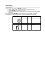
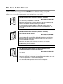
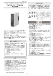
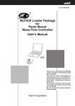
No. CP-UM-5141E
SLP-CM1 Smart Loader Package for
CMC10B Communication Controller
(CPL/CPL Converter)
User’s Manual
LOADER
2 3 4
1
0
5
9
6
8 7 ×10
1
0
power
SD
2
RD
HOST CMC
CMC ADDRESS
2 3 4
1
0
5
9
6
8 7 ×10
HOST CMC
B.RATE
RD
CMC LOCAL
SD
11
12
13
14
ERR
15
RESET
CMC10
Thank you for purchasing the SLP-CM1
for CMC10B Communication Controller
(CPL/CPL Converter).
This manual contains information for
ensuring correct use of the SLP-CM1. It
also provides necessary information for
installation, maintenance, and troubleshooting.
This manual should be read by those
who design and maintain devices that
use the CMC10B.
Be sure to keep this manual nearby for
handy reference.
NOTICE
Be sure that the user receives this manual before the product is used.
Copying or duplicating this user’s manual in part or in whole is forbidden. The information and specifications in this manual are subject to
change without notice.
Considerable effort has been made to ensure that this manual is free
from inaccuracies and omissions. If you should find an error or omission, please contact the azbil Group.
In no event is Azbil Corporation liable to anyone for any indirect, special
or consequential damages as a result of using this product.
© 2000-2013 Azbil Corporation All Rights Reserved.
Unpacking
Check the following when removing the SLP-CM1 from its package.
1. Check the model No. to make sure that you have received the product that you ordered.
2. Check the SLP-CM1 for any apparent physical damage.
3. Check the contents of the package against the Package List to make sure that all accessories are included
in the package.
After unpacking, handle the SLP-CM1 and its accessories taking care to prevent damage or loss of parts.
If an inconsistency is found or the package contents are not in order, immediately contact your dealer.
Name
SLP-CM1
System disk
Model No.
SLP-CM1E50
Dedicated cable (1 set)
User’s Manual
—
CP-UM-5141E
i
Q’ty
1
Remarks
CD-ROM
1
1
This manual
The Role of This Manual
In all, three manuals have been prepared for the CMC10B. Read the manual according to your specific
requirements. The following lists all the manuals that accompany the CMC10B and gives a brief outline of the
manual. If you do not have the required manual, contact the azbil Group or your dealer.
CP-U
M-0123
Manual
User's
WARNING
CAUTION
WARN
CAUTI
CMC10B Communication Controller (CPL/CPL Converter)
ING
ON
Manual No.CP-UM-5129E
This manual is packaged with the CMC10B.
It describes only precautions and how to manual the CMC10B. Be sure to
read this manual when installing and wiring the CMC10B.
For further details on how to handle the CMC10B, read the CMC10B
Communication Controller (CPL/CPL Converter) Design Manual No. CPSP-1064E.
CMC10B Communication Controller (CPL/CPL Converter)
User’s Manual (Design Manual)
Manual No.CP-SP-1064E
This manual is required reading for those who use the CMC10B, those who
design hardware for integrating the CMC10B into operator control panels,
those who carry out maintenance, and those who operate instruments in
which the CMC10B is integrated.
It describes an outline of the CMC10B, how to install and wire for
integrating the CMC10B into other devices, communications functions,
troubleshooting and specifications.
SLP-CM1 Smart Loader Package for CMC10B Communication
Controller (CPL/CPL Converter) User’s Manual
Manual No.CP-UM-5141E
This manual.
This manual is packaged with the SLP-CM1 system disk.
Running the SLP-CM1 package on a personal computer enables you to set
up CMC10B parameters on the personal computer.
This manual describes operations on the personal computer.
ii
Organization of This User’s Manual
This manual is organized as follows.
Chapter 1. INTRODUCTION
Be sure to read this chapter before you start using the Smart Loader Package.
This chapter describes the required operating environment for the personal
computer, how to install the package, and briefly introduces its features.
Chapter 2. INSTALLATION & BASIC FUNCTIONS
This chapter describes how to install, start up and quit the SLP-CM1, its
functions, screen configurations and basic operations.
Chapter 3. METHODS OF OPERATION
This chapter describes methods of operations relating to the setup such as the
environment setup, file operations, communications with the CMC10B and data
setup.
Chapter 4. TROUBLESHOOTING
This chapter describes error messages that are displayed when trouble occurs, and
how to remedy trouble.
Conventions Used in This Manual
The following conventions are used in this manual.
Handling Precautions
: Handling Precautions indicate items that the user should pay attention
to when handling the SLP-CM1.
Note
: Notes indicate useful information that the user might benefit by
knowing.
(1) (2) (3)
: Circled numbers indicate steps in a sequence or indicate
corresponding parts in an explanation.
[Open] button
: Indicates a selection button in screens displayed on the personal
computer.
[File], [Monitor], [Save] : Indicates messages and menus displayed on the personal computer.
>>
: Indicates the result of an operation, details displayed on the personal
computer or devices, or the state of a device after an operation.
[TAB] key, [F4] key
: Indicates keys on the keyboard.
[Ctrl]+[X] key
: Indicates the operation of pressing the [X] key with the [Ctrl] key on the
keyboard held down.
iii
Contents
Unpacking
The Role of This Manual
Organization of This User's Manual
Conventions Used in This Manual
Chapter 1.
INTRODUCTION
1-1 Outline of the SLP-CM1 • • • • • • • • • • • • • • • • • • • • • • • • • • • • • • • • • • • • • • • • • • • • • • • • • • • • • 1
1-2 System Operating Environment • • • • • • • • • • • • • • • • • • • • • • • • • • • • • • • • • • • • • • • • • • • • • 2
■ Hardware • • • • • • • • • • • • • • • • • • • • • • • • • • • • • • • • • • • • • • • • • • • • • • • • • • • • • • • • • • • • • • • • 2
■ Hardware Configuration • • • • • • • • • • • • • • • • • • • • • • • • • • • • • • • • • • • • • • • • • • • • • • • • • 2
■ Personal Computer Used for Confirmation of Operating Environment • • 2
Chapter 2.
INSTALLATION & BASIC FUNCTIONS
2-1 Installation, Starting up and Quitting the Software Package • • • • • • • • • • • • • • • • 3
■ Installation • • • • • • • • • • • • • • • • • • • • • • • • • • • • • • • • • • • • • • • • • • • • • • • • • • • • • • • • • • • • • • 3
■ Installing the device driver • • • • • • • • • • • • • • • • • • • • • • • • • • • • • • • • • • • • • • • • • • • • • • 6
■ Uninstalling the device driver • • • • • • • • • • • • • • • • • • • • • • • • • • • • • • • • • • • • • • • • • • 12
■ Starting Up SLP-CM1 • • • • • • • • • • • • • • • • • • • • • • • • • • • • • • • • • • • • • • • • • • • • • • • • • • • 13
■ Quitting SLP-CM1 • • • • • • • • • • • • • • • • • • • • • • • • • • • • • • • • • • • • • • • • • • • • • • • • • • • • • • 13
2-2 Description of Functions • • • • • • • • • • • • • • • • • • • • • • • • • • • • • • • • • • • • • • • • • • • • • • • • • • • 14
■ SLP-CM1 Functions • • • • • • • • • • • • • • • • • • • • • • • • • • • • • • • • • • • • • • • • • • • • • • • • • • • • 14
2-3 Screen Configuration • • • • • • • • • • • • • • • • • • • • • • • • • • • • • • • • • • • • • • • • • • • • • • • • • • • • • • 15
■ SLP-CM1 Screen Configuration • • • • • • • • • • • • • • • • • • • • • • • • • • • • • • • • • • • • • • • • 15
2-4 List of Operations • • • • • • • • • • • • • • • • • • • • • • • • • • • • • • • • • • • • • • • • • • • • • • • • • • • • • • • • • • 16
■ Menu Screen • • • • • • • • • • • • • • • • • • • • • • • • • • • • • • • • • • • • • • • • • • • • • • • • • • • • • • • • • • • 16
■ Edit Screen • • • • • • • • • • • • • • • • • • • • • • • • • • • • • • • • • • • • • • • • • • • • • • • • • • • • • • • • • • • • • 16
■ Monitor Screen • • • • • • • • • • • • • • • • • • • • • • • • • • • • • • • • • • • • • • • • • • • • • • • • • • • • • • • • • 16
Chapter 3. METHODS OF OPERATION
3-1 Setting up the Environment • • • • • • • • • • • • • • • • • • • • • • • • • • • • • • • • • • • • • • • • • • • • • • • • 17
3-2 File Operations • • • • • • • • • • • • • • • • • • • • • • • • • • • • • • • • • • • • • • • • • • • • • • • • • • • • • • • • • • • • 18
■ Making New Files • • • • • • • • • • • • • • • • • • • • • • • • • • • • • • • • • • • • • • • • • • • • • • • • • • • • • • 18
■ Opening Existing Files • • • • • • • • • • • • • • • • • • • • • • • • • • • • • • • • • • • • • • • • • • • • • • • • • 18
■ Overwriting and Saving Files • • • • • • • • • • • • • • • • • • • • • • • • • • • • • • • • • • • • • • • • • • 18
■ Saving Files With a New Name • • • • • • • • • • • • • • • • • • • • • • • • • • • • • • • • • • • • • • • • • 19
■ Outputting CSV Format Files • • • • • • • • • • • • • • • • • • • • • • • • • • • • • • • • • • • • • • • • • • • 19
3-3 Communications with the CMC10B • • • • • • • • • • • • • • • • • • • • • • • • • • • • • • • • • • • • • • • • 20
■ Communicating to the SLP-CM1 from the CMC10B
(reading to SLP-CM1) • • • • • • • • • • • • • • • • • • • • • • • • • • • • • • • • • • • • • • • • • • • • • • • • • • • 20
■ Communicating to the CMC10B from the SLP-CM1
(writing from SLP-CM1) • • • • • • • • • • • • • • • • • • • • • • • • • • • • • • • • • • • • • • • • • • • • • • • • 20
iv
3-4 Setting Up Data • • • • • • • • • • • • • • • • • • • • • • • • • • • • • • • • • • • • • • • • • • • • • • • • • • • • • • • • • • • • 21
■ Selecting Setup Items • • • • • • • • • • • • • • • • • • • • • • • • • • • • • • • • • • • • • • • • • • • • • • • • • • 21
■ Entering Numerical Data • • • • • • • • • • • • • • • • • • • • • • • • • • • • • • • • • • • • • • • • • • • • • • • 21
3-5 Monitor • • • • • • • • • • • • • • • • • • • • • • • • • • • • • • • • • • • • • • • • • • • • • • • • • • • • • • • • • • • • • • • • • • • • 23
■ Monitoring the CMC10B • • • • • • • • • • • • • • • • • • • • • • • • • • • • • • • • • • • • • • • • • • • • • • • • 23
■ Executing Auxiliary Functions • • • • • • • • • • • • • • • • • • • • • • • • • • • • • • • • • • • • • • • • • 23
Chapter 4. TROUBLESHOOTING
4-1 Error Messages • • • • • • • • • • • • • • • • • • • • • • • • • • • • • • • • • • • • • • • • • • • • • • • • • • • • • • • • • • • • 24
■ Communications Error Messages • • • • • • • • • • • • • • • • • • • • • • • • • • • • • • • • • • • • • • 24
■ File Error Messages • • • • • • • • • • • • • • • • • • • • • • • • • • • • • • • • • • • • • • • • • • • • • • • • • • • • 24
■ Startup Error Messages • • • • • • • • • • • • • • • • • • • • • • • • • • • • • • • • • • • • • • • • • • • • • • • • 24
v
Chapter 1.
1-1
INTRODUCTION
Outline of the SLP-CM1
The SLP-CM1 is an engineering tool for the CMC10B Communication Controller.
The SLP-CM1 software package runs on Windows XP Home Edition/XP Professional/Vista (32 bit type)/
7 (32 bit type, 64 bit type) (simply called “Windows” from here on) on a personal computer.
The SLP-CM1 has the following functions:
(1) Parameter setup
(2) Communications with CMC10B (reading/writing of parameters)
(3) File operations (reading/writing of parameters)
Note
Install SLP-CM1 on the hard disk following the procedure in “■ Installation”
(page 3).
Use the system disk that you have purchased as the backup system.
Handling Precautions
This disk do not contain the system, and cannot be used as they are.
1
Chapter 1. INTRODUCTION
1-2
System Operating Environment
The following system environment is required for using the SLP-CM1.
■ Hardware
Item
Personal
Computer
Target model
Memory
Operating system
Display
USB port
Hard disk drive
CD-ROM drive
Pointing device
Peripheral
Devices
Description
PC/AT compatibles with a Pentium chip or higher
32MB or more
Windows XP Home Edition/XP Professional/Vista (32 bit type)/
7 (32 bit type, 64 bit type)
Windows compatible display connectable to or built-into computer body
1ch or more.
Hard disk with at least 40MB of free space
1 drive or more.
Windows compatible mouse or equivalent device
Handling Precautions
Before starting up SLP-CM1, quit all other applications.
If you start up SLP-CM1 while another application is running, SLP-CM1
may malfunction.
■ Hardware Configuration
SLP-CM1
Data disk
CMC10B
LOADER
2 3 4
1
0
5
9
8 76
1
0
Communications
power
SD
2
RD
HOST CMC
CMC ADDRESS
2 3 4
1
0
5
9
8 76
Reading/Saving
Special cable (provided)
HOST CMC
B.RATE
RD
CMC LOCAL
SD
11
12
13
14
ERR
15
RESET
CMC10
■ Personal Computer Used for Confirmation of Operating Environment
Manufacturer
2
Model No.
Dell
OptiPlex Gxi5200
Dell
OptiPlex GX5166
Fujitsu
FMV-5166T3
Chapter 2.
2-1
INSTALLATION & BASIC FUNCTIONS
Installation, Starting up and Quitting the Software Package
■ Installation
This section describes how to install the SLP-CM1 on a personal computer.
Handling Precautions
If you start up the Installer while another application is running, the Installer
may malfunction.
Remove other resident applications from their directories before starting up
the Installer.
The SLP-CM1 sometimes cannot be started up depending on the combination
of other applications and drivers.
For details on Windows and personal computer settings, refer to the User’s
Manuals provided with Windows and the personal computer.
● Installing the SLP
(1) Put the CD in the CD-ROM drive of your personal computer.
>> The following screen appears for installing the driver for the USB loader
cable and selecting a SLP model.
(2) Click the [Install SLP] button.
>> The following screen appears:
(3) Click the [Next >] button.
>> The following screen appears:
3
Chapter 2. INSTALLATION & BASIC FUNCTIONS
(4) Click the [Agree >] button.
>> The following screen appears:
(5) If you agree to the software license agreement and wish to install the loader,
click the [Next >] button. If you want to abort the installation, click the
[Cancel] button.
>> After clicking the [Next >] button, the following screen appears:
Note
• To change the installation destination directory, click the [Browse...]
button.
4
Chapter 2. INSTALLATION & BASIC FUNCTIONS
(6) Click the [Next >] button.
>> The following screen appears:
Note
• To change the group, enter the new group name.
(7) Click the [Next >] button.
>> The following screen appears:
(8) Click the [Next >] button.
>> The following screen appears:
5
Chapter 2. INSTALLATION & BASIC FUNCTIONS
(9) Click the [Finish >] button.
>> When the installation is completed successfully, the display will return to
the Windows desktop.
■ Installing the device driver
A device driver must be installed before using the USB loader cable.
Follow the procedure below to install the device driver.
Handling Precautions
• Be sure to follow the procedure below when installing the device driver.
The USB cable may not be recognized if the procedure is not followed. If
the cable is not recognized, uninstall the driver and then install it again.
• Administrator privileges on the computer are required for driver installation. Installation should be done by the administrator or by a user who
belongs to the administrator group. The USB loader cable is supported
on Windows XP/Vista (32 bit type)/7 (32 bit type, 64 bit type). It is not
supported on Windows XP(64 bit type), or on Windows 2000, Windows
95, Windows NT, MS-DOS or PC-DOS.
• If there are multiple USB ports, connect the USB loader cable to the
same port every time. If it is connected to a different port, there is a
chance that driver installation may be required again.
6
Chapter 2. INSTALLATION & BASIC FUNCTIONS
1. Put the SLP CD-ROM into the CD-ROM drive of the personal computer.
>>The installation program is then started up automatically and the following
screen appears:
(1) Click the [Install USB loader cable driver] button.
>> The following screen appears:
(2) Click the [Next >] button.
>> The following screen appears:
(3) Select [AGREE] and click the [Next>] button.
>>The following screen appears :
7
Chapter 2. INSTALLATION & BASIC FUNCTIONS
(4) Click the [Continue Anyway] button.
>>The installation program then starts up, and after it is completed, the following screen appears:
(5) Click [Finish] button to complete the installation.
2. Insert the USB loader cable into the USB port.
>>When Windows recognizes the USB cable, the notification shown below
appears on the task tray and the driver installation wizard appears.
8
Chapter 2. INSTALLATION & BASIC FUNCTIONS
3. Install the device driver.
(1) Usually, when Windows recognizes the USB loader cable, the window shown
below appears. (In some cases, depending on the Windows environment, it
may not appear.) Select [No, not this time] and click the [Next >] button.
(2) For the retrieval location of the device driver to be installed, select the [Install
the software automatically (Recommended)] and click the [Next >] button.
>>Retrieval of the device driver starts.
>>When the device driver is found, the following window appears:
9
Chapter 2. INSTALLATION & BASIC FUNCTIONS
(3) Click [Continue Anyway].
>>Installation of the device driver starts
>>When the device driver installation is complete, the following window appears:
(4) Click [Finish].
>>When the installation is complete, the notification shown below appears on
the task tray, and Windows now correctly recognizes the USB loader cable.
10
Chapter 2. INSTALLATION & BASIC FUNCTIONS
(5) Select [Control Panel] → [System] → [Hardware] → [Device Manager]
(for Windows XP), [Control Panel] → [Device Manager] (for Windows
Vista/7), and find the port number for the Yamatake USB Loader Comm. from
[Ports (COM & LPT)].
(6) Start the SLP, select [Menu] → [Option], and set to the communications port
number obtained in the previous step. Then press the [OK] button to complete
the configuration.
Note
• If the CD-ROM for the SLP is not available, execute [drvsetup.exe] (32 bit type)
or [drvsetup64.exe] (64 bit type) on the computer on which the SLP is installed.
Then install the device driver.
Normally [C:\Program Files\slp\SLPCM1] (32 bit type), or
[C:\Program Files(x86)\slp\SLPCM1] (64 bit type).
11
Chapter 2. INSTALLATION & BASIC FUNCTIONS
■ Uninstalling the device driver
Handling Precautions
• Removing the driver requires restarting the computer. Close other
applications first, and then uninstall the driver.
• To uninstall the driver, administrator rights are required on the computer.
Uninstalling should be done by the administrator or by a user who
belongs to the administrator group.
1.
Execute the driver removal program.
(1) Go to [Control Panel] → [Add or Remove Programs] and click on
[Windows Driver Package - Yamatake (YC slp) USB (04/10/2008
2.0.2.8)]. Click the [Change/Remove] button.
(2) Click the [Yes] button.
(3) Restart the computer.
12
Chapter 2. INSTALLATION & BASIC FUNCTIONS
■ Starting Up SLP-CM1
(1) Click [Start] on the task bar, and click the SLP-CM1 (CMC10B) under
[Programs]-[SLP].
>> The SLP-CM1 is started up, and the menu window is displayed.
Note
For details on the operating system and the mouse you are using, refer to the
User’s Manual provided with Windows.
• Dialog box displayed when [Help] → [Version(A)] command is selected.
■ Quitting SLP-CM1
(1) Click [close] at the top right of the screen.
The operation is the same by selecting the [Menu]-[Quit] command.
>> The following screen appears:
(2) Click [OK].
13
Chapter 2. INSTALLATION & BASIC FUNCTIONS
2-2
Description of Functions
■ SLP-CM1 Functions
The SLP-CM1 is provided with the following functions for configuring CMC10B
functions:
•
•
•
•
Parameter Editing Function
File Management Function
Data Communications Function
Monitor Function
The figure below shows operations available by these functions.
Functions
Setup Function
Parameter Editing Function
• Creates and edits parameters.
File Management Function
• Saves created data to a file on floppy disk
or hard disk.
• Reads saved files for re-editing.
Data Communications Function
• Writes created data to the CMC10B.
• Reads from the CMC10B to the SLP-CM1.
Monitor Function
• Monitors the CMC10B.
• Changes addresses.
• Changes the folder mode.
• Displays the connection.
• Displays the results of self-diagnosis.
• Displays the Communication Test window.
Note
“One file” refers to data for one CMC10B.
Each file comprises the various parameter settings and the model number
information.
14
Chapter 2. INSTALLATION & BASIC FUNCTIONS
2-3
Screen Configuration
■ SLP-CM1 Screen Configuration
• Basic SLP-CM1 screen
Setup items
Menu bar
Button bar
Selection
window
Message window
15
Chapter 2. INSTALLATION & BASIC FUNCTIONS
2-4
List of Operations
■ Menu Screen
Menu
Menu
Help
Sub Menu 1
Sub Menu 2
Description
Shortcut keys
Setup
Displays the Setup window.
Monitor
Displays the Monitor window.
Ctrl+S
Ctrl+M
Environment Setup
Changes the environment setup.
Ctrl+E
Quit
Quits the Smart Loader Package.
Ctrl+Q
Version (A)
Displays the version information.
Ctrl+A
■ Edit Screen
Menu
File
Sub Menu 1
Sub Menu 2
Description
Shortcut keys
New
Create a new data
Ctrl+N
Open
Opens a existing data
Ctrl+O
Save
Saves the active data
Ctrl+S
Save As
Saves the active data with a new name
Ctrl+A
CSV Out (X)
Saves the active data in CSV format
Ctrl+X
Quit
Quits the application
Ctrl+Q
Bit input
Inputs to bit lists.
Ctrl+B
Copy
Stores the copy source.
Ctrl+C
Paste
Pastes the stored copy data.
Ctrl+V
Communication
Read (CMC10B to SLP)
Write (SLP to CMC10B)
Reads the device data.
Write the data to the device.
Ctrl+R
Ctrl+W
Setup
Communication
Host (A)
Displays the host setup.
Ctrl+Shift+A
Local (B)
Displays the local setup.
Ctrl+Shift+B
Local
Configuration (C)
Displays the host setup.
Ctrl+Shift+C
Edit
Folder
Buffer data
configuration
Option
Option
Number of folder (D) Displays the number of folder setup.
Ctrl+Shift+D
Folder size (E)
Ctrl+Shift+E
Displays the folder size setup.
Data 1001-1100 (F) Displays data 1001 to 1100.
Data 1101-1200 (G) Displays data 1101 to 1200.
Ctrl+Shift+F
Ctrl+Shift+G
Data 1201-1300 (H) Displays data 1201 to 1300.
Ctrl+Shift+H
Data 1301-1400 (I)
Displays data 1301 to 1400.
Ctrl+Shift+I
Data 1401-1500 (J)
Displays data 1401 to 1500.
Ctrl+Shift+J
Data 1501-1600 (K)
Displays data 1501 to 1600.
Ctrl+Shift+K
Data 1601-1700 (L)
Displays data 1601 to 1700.
Ctrl+Shift+L
Data 1701-1800 (M) Displays data 1701 to 1800.
Ctrl+Shift+M
Data 1801-1868 (N) Displays data 1801 to 1868.
Ctrl+Shift+N
Other (O)
Environment Setup
Displays other information.
Ctrl+Shift+O
Changes the environment setup.
Ctrl+E
■ Monitor Screen
Menu
Sub Menu 2
Description
Shortcut keys
File
Quit
Quits the monitor window.
Ctrl+Q
Monitor
Start/Stop (M)
Starts/stops the monitor.
Ctrl+M
Address
Changes the monitor start address.
Backward
Advances the address backward.
Option
16
Sub Menu 1
Forward
Advances the address forward.
Display in hexadecimal
Displays the monitor in hexadecimal.
Folder mode
Changes the folder mode.
Connection
Displays the connection.
Self diagnosis
Displays the results of Self-diagnosis.
Communication test (L)
Displays the Communication test window.
Chapter 3.
3-1
METHODS OF OPERATION
Setting up the Environment
Set the communications port and font on the personal computer.
(1) Click [Environment Setup].
The operation is the same by selecting the [Option]-[Environment Setup]
command or the [Ctrl]+[E] keys.
>> The Environment Setup dialog box appears.
(2) Set the communications port. Select the various settings.
(3) Set the font size. Select the various settings.
(4) Click [OK].
Handling Precautions
Normally, use “COM1”.
Even if another communications port can be selected, it sometimes
cannot be used depending on its shape.
17
Chapter 3. METHODS OF OPERATION
3-2
File Operations
■ Making New Files
(1) Click [New].
The operation is the same by selecting the [File]-[New] command or the
[Ctrl]+[N] keys.
>> The New dialog box appears.
(2) Click [OK].
>> A new file opens.
■ Opening Existing Files
(1) Click [Open].
The operation is the same by selecting the [File]-[Open] command or the
[Ctrl]+[O] keys.
>> The [Open] dialog box appears.
(2) Select the folder name in [Look in...].
(3) Click (select) the file name.
(4) Click [Open].
>> The file having the name that you set opens.
■ Overwriting and Saving Files
(1) Click (select) [Save].
The operation is the same by selecting the [File]-[Save] command or the
[Ctrl]+[S] keys.
>> The file is overwritten and saved.
18
Chapter 3. METHODS OF OPERATION
■ Saving Files With a New Name
(1) Select the [File]-[Save As] command.
The operation is the same by selecting the [Ctrl]+[A] keys.
>> The [Save As] dialog box appears.
(2) Select the folder name under [Save in:].
(3) Enter the file name to [File name].
(4) Click [Save].
>> The file is saved under the file name that you set.
Note
The file is overwritten and saved when you click (select) the file name at the
[File name] window.
■ Outputting CSV Format Files
(1) Select the [File]-[CSV Out (X)] command.
The operation is the same by selecting the [Ctrl]+[X] keys.
>> The CSV output dialog box appears.
(2) Select the folder name under [Save in:].
(3) Enter the file name to [File name].
(4) Click [Save].
>> The file is output under the file name that you set.
Note
The file is overwritten and saved when you click (select) the file name at the
[File name] window.
A CSV format file is a text file delimited by commas, and can be used in
Microsoft Excel or other off-the-shelf spreadsheet applications.
19
Chapter 3. METHODS OF OPERATION
3-3
Communications with the CMC10B
■ Communicating to the SLP-CM1 from the CMC10B (reading to SLP-CM1)
(1) Click [Read (CMC10B to SLP)].
The operation is the same by selecting the [Communication][Read (CMC10B to SLP)] command or the [Ctrl]+[R] keys.
>> The Confirm dialog box appears.
(2) Click [OK].
>> Reading to the SLP-CM1 starts.
■ Communicating to the CMC10B from the SLP-CM1 (writing from SLP-CM1)
(1) Click [Write (SLP to CMC10B)].
The operation is the same by selecting the [Communication][Write (SLP to CMC10B)] command or the [Ctrl]+[W] keys.
>> The Confirm dialog box appears.
(2) Click [OK].
>> Writing to the CMC10B starts.
20
Chapter 3. METHODS OF OPERATION
3-4
Setting Up Data
■ Selecting Setup Items
● Moving the highlight section on the display by operating the keyboard
(1) Press the [↑], [↓], [←] or [→] key to move the highlighted section on screen.
● Moving the highlight section on the display by operating the mouse
(1) Click the section you want to move.
(2) Click the scroll bar to scroll the screen.
>> The screen cannot be scrolled beyond the topmost or bottommost rows on
screen.
● Changing operation windows
(1) Press the [TAB] key.
>> The screen moves to the target operation window.
Note
Setup items are moved to in order on screen.
■ Entering Numerical Data
● Entering numerical values
The following describes how numerical values are entered:
• To enter a numerical value, press the [0] to [9] keys on the keyboard.
• To enter a hexadecimal number, press the [0] to [9] keys or the [A] to [F] keys on
the keyboard.
• To enter a decimal point, press the [.] key at the desired decimal point position.
• To enter a minus value, press the [—] key.
• To cancel a wrong entry, press the [BACK SPACE] key.
>> The current displayed value is deleted.
• To cancel the currently entered numerical value, press the [ESC] key.
>> Original set value is redisplayed.
● Entering values to setup items
Use the [0] to [9] keys on the keyboard to enter values to setup items.
(1) Select the setup item to highlight it.
(2) Enter the desired set value by the [0] to [9] keys.
(3) Press the [ENT] key.
The operation is the same by pressing the [↑] or [↓] key.
>> The set value is fixed.
Note
• After you have fixed the numerical value by pressing the [↑] or [↓] key, the
highlight section moves on screen.
When you have moved a setup item using the mouse, the set value is not
fixed.
• When a set value is invalid, the original set value is redisplayed.
To cancel a set value midway during entry, press the [ESC] key before you
fix the set value.
21
Chapter 3. METHODS OF OPERATION
● Selecting and entering data
Note
Items that can be selected and entered are automatically displayed.
(1) Press a setup item button.
The operation is the same by selecting the [TAB] or [ALT]+[↓] keys.
>> Selection Item is displayed.
Selection item
(2) Select the setup item by the mouse.
The operation is the same by selecting the [↑], [↓], [←] or [→] key, or the
[ENT] key.
>> The set value is fixed.
Note
When you use the mouse, the set value is fixed at the same time that you
select it with the mouse.
22
Chapter 3. METHODS OF OPERATION
3-5
Monitor
The following monitor screen is displayed if you select [Monitor] in the menu window (page 5) that is displayed
when the SLP-CM1 is started up.
The following describes the operations available in the monitor screen.
■ Monitoring the CMC10B
• To start monitoring
Select the [Monitor]-[Start] command.
The operation is the same by selecting the [Ctrl]+[M] keys.
• To stop monitoring
Select the [Monitor]-[Stop] command.
The operation is the same by selecting the [Ctrl]+[M] keys.
• To change the address to be monitored
Select the [Monitor]-[Address] command.
■ Executing Auxiliary Functions
• To change the folder mode
Select the [Option]-[Folder mode] command.
• To check the connection
Select the [Option]-[Connection] command.
• To display the results of self-diagnosis
Select the [Option]-[Self diagnosis] command.
• To display the Communication test screen
Select the [Option]-[Communication test] command.
In the Communication test screen, you can send CPL commands to the
CMC10B.
23
Chapter 4.
4-1
TROUBLESHOOTING
Error Messages
■ Communications Error Messages
Message
Category
Communications “Time out”
error
“Cannot open
communications port”
CMC10B status
error
“Communications error
has occurred”
“Check currently
connected instruments.”
“Cannot support
currently connected
CMC10B”
Remedy
Check cable connections and
contacts.
Do not use the communications
port at the same time as software
that is using other
communications ports.
Quit SLP-CM1, and reboot
A system error occurred.
Windows95/98.
Currently connected instrument is Connect the CMC10B before
not an CMC10B. Or, CMC10B is use.
not connected.
Contact your dealer.
Versions of SLP-CM1 and
CMC10B in use are not
supported.
Description
Could not receive message
during time out preset time.
Could not open communications
port.
■ File Error Messages
Category
File name error
Disk error
Message
“This filename is not
valid.”
“This file cannot be
found. Make sure that
the correct path and
filename are given.”
“This filename is a
reserved device name.
Use a different
filename.”
“Not enough free space
on disk”
“The device is not
ready.”
“Cannot make file”
“File name too long”
Description
An invalid file name has been
entered.
A non-existent file name has
been entered.
Remedy
Enter the correct file name.
A file name reserved as a device
name has been entered.
Enter the correct file name.
There is not enough free space
on disk.
The disk is not prepared.
Secure enough free space on
disk.
Prepare a disk, and repeat the
operation.
Save to a different destination.
The save destination is a CDROM.
The file name is too long.
Path name error “The path does not exist. An illegal path name has been
entered.
Make sure that the
correct path is given.”
File information “Illegal file size”
File is damaged.
error
“Illegal file information”
Correctly enter the name of an
existent file.
Limit file names to 255 or less
characters.
Enter the correct path name, and
repeat the operation.
Damaged files cannot be used.
Make a new file.
■ Startup Error Messages
Category
SLP-CM1
system error
24
Message
“Cannot start up two or
more SLP-CM1s at
once.”
Description
An attempt was made to start up
two or more SLP-CM1s at once.
Remedy
Press the [OK] button.
Revision History
Printed
Date
Manual Number
Edition
Revised pages
Description
June 2000 CP-UM-5141E 1st Edition
Dec. 2008
2nd Edition 3 to 5
Apr. 2012
3rd Edition
4th Edition
Apr. 2013
Cover, i, ii, 2
1, 2
3
6 to 12
13 to 24
2-1 Installation, Starting up and Quitting the
Software Package changed.
Company name changed.
Floppy disk→CD-ROM
Operating Environment,
Windows 95/98/Me/2000/XP changed to
Windows XP Home Edition/XP Professional/
Vista (32 bit type)/7 (32 bit type, 64 bit type).
Serial port→USB port
About Serial port explanation deleted.
Explanation of “● Installing the SLP” was
changed.
“ ■ Installing the device driver” and
“ ■ Uninstalling the device driver” were added.
Old 7 to 18 page.
Terms and Conditions
We would like to express our appreciation for your purchase and use of Azbil Corporation's products.
You are required to acknowledge and agree upon the following terms and conditions for your purchase of Azbil Corporation's
products (field instruments, control valves, and control products), unless otherwise stated in any separate document,
including, without limitation, estimation sheets, written agreements, catalogs, specifications and instruction manuals.
1. Warranty period and warranty scope
1.1 Warranty period
Azbil Corporation's products shall be warranted for one (1) year from the date of your purchase of the said
products or the delivery of the said products to a place designated by you.
1.2 Warranty scope
In the event that Azbil Corporation's products has any failure attributable to azbil during the aforementioned warranty
period, azbil shall, without charge, deliver a replacement for the said product to the place where you purchased, or
repair the said product and deliver it to the aforementioned place.
Notwithstanding the foregoing, any failure falling under one of the following shall not be covered under this warranty:
(1) Failure caused by your improper use of Azbil Corporation's products
(noncompliance with conditions, environment of use, precautions, etc. set forth in catalogs, specifications,
instruction manuals, etc.);
(2) Failure caused for other reasons than Azbil Corporation's products;
(3) Failure caused by any modification or repair made by any person other than azbil or azbil's
subcontractors;
(4) Failure caused by your use of Azbil Corporation's products in a manner not conforming to the intended
usage of that product;
(5) Failure that the state-of-the-art at the time of Azbil Corporation's shipment did not allow us to predict; or
(6) Failure that arose from any reason not attributable to Azbil Corporation, including, without limitation, acts
of God, disasters, and actions taken by a third party.
Please note that the term "warranty" as used herein refers to equipment-only-warranty, and Azbil Corporation
shall not be liable for any damages, including direct, indirect, special, incidental or consequential damages in
connection with or arising out of Azbil Corporation's products.
2. Ascertainment of suitability
You are required to ascertain the suitability of Azbil Corporation's products in case of your use of the same with
your machinery, equipment, etc. (hereinafter referred to as "Equipment") on your own responsibility, taking the
following matters into consideration:
(1) Regulations and standards or laws that your Equipment is to comply with.
(2) Examples of application described in any documents provided by Azbil Corporation are for your reference
purpose only, and you are required to check the functions and safety of your Equipment prior to your use.
(3) Measures to be taken to secure the required level of the reliability and safety of your Equipment in your use
Although Azbil Corporation is constantly making efforts to improve the quality and reliability of Azbil
Corporation's products, there exists a possibility that parts and machinery may break down.
You are required to provide your Equipment with fool-proof design, fail-safe design, anti-flame
propagation design, safety design, or the like so that the said Equipment may satisfy the level of the
reliability and safety required in your use, whereby preventing any occurrence of physical injuries, fires,
significant damage, and so forth.
3. Precautions and restrictions on application
Azbil Corporation's products other than those explicitly specified as applicable (e.g. azbil Limit Switch For Nuclear
Energy) shall not be used in a nuclear energy controlled area (radiation controlled area).
Any Azbil Corporation's products shall not be used for/with medical equipment.
In addition,
you are required to conduct a consultation with our sales representative and understand detail specifications,
cautions for operation, and so forth by reference to catalogs, specifications, instruction manual , etc. in case that
you intend to use Azbil Corporation's products for any purposes specified in (1) through (6) below.
Moreover, you are required to provide your Equipment with fool-proof design, fail-safe design, anti-flame
propagation design and other designs of protection/safety circuit on your own responsibility to ensure the
reliability and safety, whereby preventing problems caused by failure or nonconformity.
(1) For use under such conditions or in such environments as not stated in technical documents, including
catalogs, specification, and instruction manuals
(2) For use of specific purposes, such as:
* Nuclear energy/radiation related facilities
[For use outside nuclear energy controlled areas] [For use of Azbil Corporation's Limit Switch For
Nuclear Energy]
* Machinery or equipment for space/sea bottom
* Transportation equipment
[Railway, aircraft, vessels, vehicle equipment, etc.]
* Antidisaster/crime-prevention equipment
* Burning appliances
* Electrothermal equipment
* Amusement facilities
(3) Supply systems such as electricity/gas/water supply systems, large-scale communication systems, and
traffic/air traffic control systems requiring high reliability
(4) Facilities that are to comply with regulations of governmental/public agencies or specific industries
(5) Machinery or equipment that may affect human lives, human bodies or properties
(6) Other machinery or equipment equivalent to those set forth in items (1) to (5) above which require high
reliability and safety
4. Precautions against long-term use
Use of Azbil Corporation's products, including switches, which contain electronic components, over a prolonged
period may degrade insulation or increase contact-resistance and may result in heat generation or any other
similar problem causing such product or switch to develop safety hazards such as smoking, ignition, and
electrification.
Although acceleration of the above situation varies depending on the conditions or environment of use of the
products, you are required not to use any Azbil Corporation's products for a period exceeding ten (10) years
unless otherwise stated in specifications or instruction manuals.
5. Recommendation for renewal
Mechanical components, such as relays and switches, used for Azbil Corporation's products will reach the end of
their life due to wear by repetitious open/close operations.
In addition, electronic components such as electrolytic capacitors will reach the end of their life due to aged
deterioration based on the conditions or environment in which such electronic components are used.
Although acceleration of the above situation varies depending on the conditions or environment of use, the
number of open/close operations of relays, etc.
as prescribed in specifications or instruction manuals, or depending on the design margin of your machine or
equipment, you are required to renew any Azbil Corporation's products every 5 to 10 years unless otherwise
specified in specifications or instruction manuals.
Field instruments (sensors such as pressure/flow/level sensors, regulating valves, etc.) will reach the end of their
life due to aged deterioration of parts.
For those parts that will reach the end of their life due to aged deterioration, recommended replacement cycles are
prescribed. You are required to replace parts based on such recommended replacement cycles.
6. Other precautions
Prior to your use of Azbil Corporation's products, you are required to understand and comply with specifications
(e.g., conditions and environment of use), precautions, warnings/cautions/notices as set forth in the technical
documents prepared for individual Azbil Corporation's products, such as catalogs, specifications, and instruction
manuals to ensure the quality, reliability, and safety of those products.
7. Changes to specifications
Please note that the descriptions contained in any documents provided by Azbil Corporation are subject to change
without notice for improvement or for any other reason.
For inquires or information on specifications as you may need to check, please contact our branch offices or sales
offices, or your local sales agents.
8. Discontinuance of the supply of products/parts
Please note that the production of any Azbil Corporation's products may be discontinued without notice.
For repairable products, we will, in principle, undertake repairs for five (5) years after the discontinuance of those
products. In some cases, however, we cannot undertake such repairs for reasons, such as the absence of repair
parts.
For field instruments, we may not be able to undertake parts replacement for similar reasons.
Specifications are subject to change without notice.
(09)
1-12-2 Kawana, Fujisawa
Kanagawa 251-8522 Japan
URL: http://www.azbil.com
1st edition: June 2000 (W)
4th edition: Apr. 2013 (F)