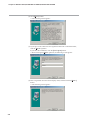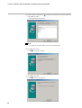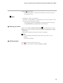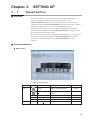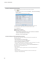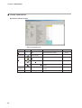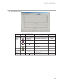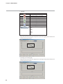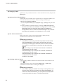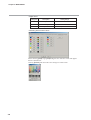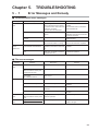
1
No. CP-UM-5290E
SLP-C35
Smart Loader Package
for
SDC15/25/26/35/36
Single Loop Controller
User's Manual
pv
sp
mode
rdy man ev1 ev2 ev3 ot1 ot2
para
Thank you for purchasing the SLP-C35
for Single Loop Controller SDC
15/25/26/35/36.
This manual contains information for
ensuring correct use of the SLP-C35. It
also provides necessary information for
installation, maintenance, and troubleshooting.
This manual should be read by those
who design and maintain devices that
use the SDC15/25/26/35/36.
Be sure to keep this manual nearby for
handy reference.
RESTRICTIONS ON USE
This product has been designed, developed and manufactured for general-purpose
application in machinery and equipment.
Accordingly, when used in applications outlined below, special care should be taken to
implement a fail-safe and/or redundant design concept as well as a periodic
maintenance program.
• Safety devices for plant worker protection
• Start/stop control devices for transportation and material handling machines
• Aeronautical/aerospace machines
• Control devices for nuclear reactors
Never use this product in applications where human safety may be put at risk.
IMPORTANT
Do not apply a strong force while connecting a loader plug. Failure to do
so might damage the instrument.
Handling Precautions
Application of excessive force to the loader plug might cause
communication failure. If such failure happens, reconnect the
loader plug correctly.
REQUEST
Ensure that this User's Manual is handed over to the user before the
product is used.
Copying or duplicating this User's Manual in part or in whole is forbidden. The information and specifications in this User's Manual are subject to change without notice.
Considerable effort has been made to ensure that this User's Manual is
free from inaccuracies and omissions.
If you should find any inaccuracies or omissions, please contact
Yamatake Corporation.
In no event is Yamatake Corporation liable to anyone for any indirect,
special or consequential damages as a result of using this product.
©2005 Yamatake Corporation ALL RIGHTS RESERVED
Unpacking
Check the following items when removing the SLP-C35 from its package:
1. Check the model No. to make sure that you have received the product that you ordered.
2. Check the SLP-C35 for any apparent physical damage.
3. Check the contents of the package against the Package List to make sure that all accessories are included
in the package.
After unpacking, handle the SLP-C35 and its accessories taking care to prevent damage or loss of parts.
If an inconsistency is found or the package contents are not in order, immediately contact your dealer.
Name
Model No.
SLP-C35 System disk
SLP-C35J50
Q'ty
Remarks
1
CD-ROM
Special cable
-
1
(1 set)
User's Manual
CP-UM-5290E
1
This manual.
i
The Role of This Manual
A total of eight different manuals are available for the SDC15/25/26/35/36. Read them as necessary for your specific requirements. If a manual you require is not available, contact Yamatake Corporation or its dealer.
123E
C P-UM-0
nual
User's Ma
WARNING
CAUTION
WARNING
CAUTION
SDC15 Single Loop Controller User's Manual "Installation"
Manual No. CP-UM-5287E
This manual is supplied with the product. Personnel in charge of design
and/or manufacture of a system using this unit must thoroughly read this
manual. This manual describes the safety precautions, installation, wiring,
list of parameters, and primary specifications. For further information about
operation, refer to other manuals, "Basic Operation" and/or "Installation &
Configurations".
SDC15 Single Loop Controller User's Manual "Basic Operation"
Manual No. CP-SP-1147E
This manual is optional (sold separately). The manual describes the
functions you can set up only with "Simple configuration". Personnel in
charge of design, manufacture, operation, and/or maintenance of a system
using this unit must thoroughly read this manual. This manual describes
the installation, wiring, major functions and settings, operating procedures,
troubleshooting, and detailed specifications.
SDC15 Single Loop Controller User's Manual "Installation &
Configurations"
Manual No. CP-SP-1148E
This manual is optional (sold separately). The manual describes the
hardware and all functions of this unit. Personnel in charge of design,
manufacture, operation, and/or maintenance of a system using this unit and
those in charge of communication software of a system using the
communication functions of this unit must thoroughly read this manual.
This manual also describes the installation, wiring, connections for
communication, all functions and settings of this unit, operating procedures,
communication with host station, such as personal computer,
communication addresses, troubleshooting, and detailed specifications.
SLP-C35 Smart Loader Package for SDC15/25/26/35/36
Single Loop Controller User's Manual
Manual No. CP-UM-5290E
This manual.
This manual is supplied with the SLP-C35 Smart Loader Package.
The manual describes the software used to make various settings for
SDC15/25/26/35/36 using a personal computer. Personnel in charge of
design or setting of a system using SDC15/25/26/35/36 must thoroughly
read this manual. The manual describes installation of the software into a
personal computer, operation of the personal computer, various functions,
and setup procedures.
ii
123E
C P-UM-0
nual
User's Ma
WARNING
CAUTION
WARNING
CAUTION
SDC25/26 Single Loop Controller User's Manual "Installation"
Manual No. CP-UM-5288E
This manual is supplied with the product. Personnel in charge of design
and/or manufacture of a system using this unit must thoroughly read this
manual. This manual describes the safety precautions, installation, wiring,
list of parameters, and primary specifications. For further information about
operation, refer to another manual, "Installation & Configurations".
SDC25/26 Single Loop Controller User's Manual "Installation &
Configurations"
Manual No. CP-SP-1149E
This manual is optional (sold separately). The manual describes the
hardware and all functions of this unit. Personnel in charge of design,
manufacture, operation, and/or maintenance of a system using this unit and
those in charge of communication software of a system using the
communication functions of this unit must thoroughly read this manual.
This manual also describes the installation, wiring, connections for
communication, all functions and settings of this unit, operating procedures,
communication with host station, such as personal computer,
communication addresses, troubleshooting, and detailed specifications.
SDC35/36 Single Loop Controller User's Manual "Installation"
Manual No.CP-UM-5289E
This manual is supplied with the product. Personnel in charge of design
and/or manufacture of a system using this unit must thoroughly read this
manual. This manual describes the safety precautions, installation, wiring,
list of parameters, and primary specifications. For further information about
operation, refer to another manual, "Installation & Configurations".
SDC35/36 Single Loop Controller User's Manual "Installation &
Configurations"
Manual No.CP-SP-1150E
This manual is optional (sold separately). The manual describes the
hardware and all functions of this unit. Personnel in charge of design,
manufacture, operation, and/or maintenance of a system using this unit and
those in charge of communication software of a system using the
communication functions of this unit must thoroughly read this manual.
This manual also describes the installation, wiring, connections for
communication, all functions and settings of this unit, operating procedures,
communication with host station, such as personal computer,
communication addresses, troubleshooting, and detailed specifications.
iii
Organization of This User's Manual
This manual is organized as follows:
Chapter 1. INTRODUCTION
Be sure to read this chapter before you start using the Smart Loader Package.
This chapter describes the required operating environment for the personal
computer, how to install the package, and briefly introduces its features.
Chapter 2. INSTALLATION, STARTINGUP AND QUITTING THE LOADER
This chapter describes how to install, start up and quit.
Chapter 3. SETTING UP
This chapter describes how to set up the data.
Chapter 4. MONITORING
This chapter describes how to change the settings, as well as the screens
monitoring the operation status.
Chapter 5. TROUBLESHOOTING
This chapter describes error messages that are displayed when trouble occurs, and
how to remedy trouble.
iv
Contents
Unpacking
The Role of This Manual
Organization of This User's Manual
Conventions Used in This Manual
Chapter 1.
INTRODUCTION
1-1 Overview • • • • • • • • • • • • • • • • • • • • • • • • • • • • • • • • • • • • • • • • • • • • • • • • • • • • • • • • • • • • • • • • • • • 1-1
■ Loader functions • • • • • • • • • • • • • • • • • • • • • • • • • • • • • • • • • • • • • • • • • • • • • • • • • • • • • • • 1-1
1-2 System Operating Environment • • • • • • • • • • • • • • • • • • • • • • • • • • • • • • • • • • • • • • • • • • • 1-2
■ Hardware • • • • • • • • • • • • • • • • • • • • • • • • • • • • • • • • • • • • • • • • • • • • • • • • • • • • • • • • • • • • • • • 1-2
■ Hardware configuration • • • • • • • • • • • • • • • • • • • • • • • • • • • • • • • • • • • • • • • • • • • • • • • • 1-3
Chapter 2.
INSTALLATION, STARTING UP AND QUITTING THE LOADER
■ Installing the loader • • • • • • • • • • • • • • • • • • • • • • • • • • • • • • • • • • • • • • • • • • • • • • • • • • • • 2-1
■ Starting up loader • • • • • • • • • • • • • • • • • • • • • • • • • • • • • • • • • • • • • • • • • • • • • • • • • • • • • • 2-5
■ Quitting loader • • • • • • • • • • • • • • • • • • • • • • • • • • • • • • • • • • • • • • • • • • • • • • • • • • • • • • • • • 2-5
Chapter 3.
SETTING UP
3-1 Setup Function • • • • • • • • • • • • • • • • • • • • • • • • • • • • • • • • • • • • • • • • • • • • • • • • • • • • • • • • • • • • 3-1
■ Overview • • • • • • • • • • • • • • • • • • • • • • • • • • • • • • • • • • • • • • • • • • • • • • • • • • • • • • • • • • • • • • • 3-1
■ Screen explanations • • • • • • • • • • • • • • • • • • • • • • • • • • • • • • • • • • • • • • • • • • • • • • • • • • • 3-1
3-2 Method of Setup • • • • • • • • • • • • • • • • • • • • • • • • • • • • • • • • • • • • • • • • • • • • • • • • • • • • • • • • • • • 3-4
Chapter 4.
MONITORING
4-1 Monitor Function • • • • • • • • • • • • • • • • • • • • • • • • • • • • • • • • • • • • • • • • • • • • • • • • • • • • • • • • • • 4-1
■ Overview • • • • • • • • • • • • • • • • • • • • • • • • • • • • • • • • • • • • • • • • • • • • • • • • • • • • • • • • • • • • • • • 4-1
■ Screen explanations • • • • • • • • • • • • • • • • • • • • • • • • • • • • • • • • • • • • • • • • • • • • • • • • • • • 4-2
4-2 Method of Operation • • • • • • • • • • • • • • • • • • • • • • • • • • • • • • • • • • • • • • • • • • • • • • • • • • • • • • • 4-5
■ How to operate the numeric monitor screen • • • • • • • • • • • • • • • • • • • • • • • • • • • 4-5
■ How to operate the trend monitor • • • • • • • • • • • • • • • • • • • • • • • • • • • • • • • • • • • • • • 4-7
Chapter 5.
TROUBLESHOOTING
5-1 Error Messages and Remedy • • • • • • • • • • • • • • • • • • • • • • • • • • • • • • • • • • • • • • • • • • • • • • 5-1
■ Communications error messages • • • • • • • • • • • • • • • • • • • • • • • • • • • • • • • • • • • • • • 5-1
■ File error messages • • • • • • • • • • • • • • • • • • • • • • • • • • • • • • • • • • • • • • • • • • • • • • • • • • • • 5-1
5-2 Other Troubleshooting• • • • • • • • • • • • • • • • • • • • • • • • • • • • • • • • • • • • • • • • • • • • • • • • • • • • • 5-2
v
Conventions Used in This Manual
The following conventions are used in this manual:
Handling Precautions :
Handling Precautions indicate items that the user should pay attention to
when handling the SLP-C35PRO.
Note :
Notes indicate useful information that the user might benefit by knowing.
:
This indicates the item or page that the user is requested to refer to.
(1), (2), (3) :
The numbers with the parenthesis indicate steps in a sequence or
indicate corresponding parts in an explanation.
[OK] button :
Indicates a selection button in screens displayed on the personal
computer.
[Option] :
Indicates messages and menus displayed on the personal computer.
>> :
Indicates the result of an operation, details displayed on the personal
computer or devices, or the state of a device after an operation.
[Ctrl] key, [A] key :
Indicates keys on the keyboard.
[Ctrl]+[A] key :
Indicates the operation of pressing the [A] key with the [Ctrl] key on the
keyboard held down.
vi
Chapter 1.
1 - 1
INTRODUCTION
Overview
This software SLP-C35 is an engineering tool for the SDC15/25/26/35/36.
Note
• Install SLP-C35 on the hard disk following the procedure in
■ Installing the loader (page 2-1).
Use the system disk that you have purchased as the backup system.
Handling Precautions
• This disk does not contain the system, and cannot be used as they are.
■ Loader functions
The loader has the following functions:
• Setup function
• Monitor function
• Adjustment function
• PID simulator function
● Setup function
This function is for setting up parameters required for running the controller on the
personal computer and writing (setting) them to the controller. For details, refer to;
Chapter 3. SETTING UP.
● Monitor function
After the setup parameters have been written to the controller, changes to and
tuning of control constants while the controller is running, switching of modes
(RUN/READY, AUTO/MANUAL, etc.), run state and alarm occurrence can be
checked.
The run state can also be checked on the Trend screen, and sampled data can be
output in CSV format so that it can be handled in third-party spreadsheet software
such as Microsoft Excel. For details, refer to;
Chapter 4. MONITORING.
Handling Precautions
• The monitor target is limited to only one unit when the loader jack on
the front panel is used for performing monitoring.
● Adjustment function
This function is used when the user adjusts controller input.
For details on the adjustment function, refer to;
SDC15 Single Loop Controller User's Manual "Installation &
Configurations" CP-SP-1148E
SDC25/26 Single Loop Controller User's Manual "Installation &
Configurations" CP-SP-1149E
SDC35/36 Single Loop Controller User's Manual "Installation &
Configurations" CP-SP-1150E.
Handling Precautions
• When the adjustment function is used, adjustment value stored on the
controller so far are discarded. (When this function is used for the first
time, the controller's default adjustment values are discarded.) Pay
sufficient attention to this when using this function.
1-1
Chapter 1. INTRODUCTION
1 - 2
System Operating Environment
The following system environment is required for using the loader:
■ Hardware
Item
Description
Personal Computer Target model
Memory
PC/AT compatibles with a Pentium chip or higher
32M byte or more
Operating system Windows98/Me/2000 Professional/XP Home/
XP Proffessional
USB Port
Serial port
9-pin, serial port, 1ch or more*
USB Port
1 port or more
Peripheral Devices Display
800 X 600 dot or more, 16 bit color or more
Hard disk drive
Hard disk with at least 40M byte of free space
CD-ROM drive
1 drive or more
Pointing device
Windows-compatible mouse or equivalent device
* : Serial port
It is recommended to use a personal computer with 9-pin serial port built-in.
If your personal computer does not have any serial port, you may use any of
the extension adaptors listed below to connect the loader cable.
However, note that the operation may become unstable depending on the
personal computer environment.
• Special interface (port replicater)
Adaptor specially designed for each personal computer (special adaptor for
each personal computer model)
• CF card adaptor
CF232 manufactured by Elan Digital systems
URL: http://www.elandigitalsystems.com/interface/cf232.php
Operation confirmed personal computer, IBM's Thinkpad A31
REX-CF60 manufacture by RATOC.
URL: http://www.ratocsystems.com/products/subpage/cf60.html(Japanese)
• USB adaptor
USB-RSAQ3 manufactured by I•O DATA DEVCE, INC.
URL: http://www.iodata.jp/prod/mobile/serial/2004/usb-rsaq3/(Japanese)
Operation confirmed personal computer, IBM's Thinkpad A31
When connecting the USB cable, check the port No.
The port No. may vary depending on the USB cable connection position.
Handling Precautions
• Before starting up loader, quit all other applications.
If you start up loader while another application is running, loader may
not function.
Also, set the power save setting, infrared communications and screen
saver to OFF.
• Make sure that the [Decimal symbol] has been set to " . " for [Control
Panel] → [Regional Settings] → [Number].
If it has been set to other character, the loader cannot correctly function.
1-2
Chapter 1. INTRODUCTION
■ Hardware configuration
● General configuration
SLP-C35
SDC15/25/26/35/36
Communications
Special cable (provided)
● Configuration with CMC10B/L
• When connecting 31 units or less
CMC10L
LOADER
11
12
13
14
15
CMC10
SDC15/25/26
35/36
Max. 31 units
• When connecting 32 units or more
CMC10L CMC10B
LOADER
CMC10B
LOADER
1
0
LOADER
RD
14
SD
RD
SD
11
12
RD
13
14
ERR
15
ERR
15
RESET
CMC10
power
2
CMC LOCAL
SD
RESET
2 3 4
1
0
5
9
6
8 7 X10
HOST CMC
B.RATE
11
12
2 3 4
1
0
5
9
6
8 7 X10
1
0
13
ERR
15
CMC10
RD
CMC LOCAL
15
RD
CMC LOCAL
11
12
13
14
SD
2
HOST CMC
B.RATE
SD
11
12
13
14
2 3 4
1
0
5
9
6
8 7 X10
HOST CMC
RD
HOST CMC
B.RATE
power
CMC ADDRESS
SD
2
2 3 4
1
0
5
9
6
8 7 X10
HOST CMC
1
0
CMC ADDRESS
2 3 4
1
0
5
9
6
8 7 X10
CMC10B
LOADER
power
HOST CMC
CMC ADDRESS
2 3 4
1
0
5
9
6
8 7 X10
RESET
CMC10
CMC10
SDC15/25/26
35/36
Max. 31 units
Max. 31 units
Max. 31 units
Note
• The CMC10B allows up to 31 units to be connected to a host device.
Note
• Personal computer used for confirmation of operating environment
Manufacturer
Model No.
Dell
OptiPlex GX110
IBM
Think Pad A31
1-3
Chapter 2. INSTALLATION, STARTING UP AND QUITTING THE LOADER
■ Installing the loader
This section describes how to install the loader on a personal computer.
Handling Precautions
• If you start up the Installer while another application is running, the
Installer may malfunction.
Remove other resident applications from their directories before starting
up the Installer.
The SLP-C35 sometimes cannot be started up depending on the
combination of other applications and drivers.
For details on Windows and personal computer settings, refer to the
User’s Manuals provided with Windows and the personal computer.
● Installing loader
(1) Set the CD-ROM in the CD-ROM drive of your personal computer.
>>The installation program is then started up automatically and the following
screen appears:
If the SLP-C35 having the old version has been installed, the screen shown
below appears.
Click the [OK] button to uninstall the SLP-C35 having the old version.
2-1
Chapter 2. INSTALLATION, STARTING UP AND QUITTING THE LOADER
(2) Click [Next >] button.
>>The following screen appears :
(3) If you agree to the software license agreement and wish to install the loader,
click the [Agree >] button.
If you abort the installation, click the [Don’t agree] button.
>>When clicking the [Agree >] button, the following screen appears :
(4) Enter a registered user name and company name, and then click the [Next >]
button.
>>The following screen appears :
2-2
Chapter 2. INSTALLATION, STARTING UP AND QUITTING THE LOADER
(5) Click [Next >] button.
>>The following screen appears :
Note
• To change the installation destination directory, click [Browse...] button.
(6) Click [Next >] button.
>>The following screen appears :
Note
• Check on necessary files.
To display a PDF file, it is absolutely necessary to install Acrobat Reader.
For details, refer to;
Note on page 2-5.
2-3
Chapter 2. INSTALLATION, STARTING UP AND QUITTING THE LOADER
(7) Check on (put a check mark :
) software components you wish to install and
click [Next >] button.
>>The following screen appears :
Note
• To change the program folder, enter the new folder name.
(8) Click [Next >] button.
>>The following screen appears :
(9) Click [Next >] button.
>>The following screen appears :
2-4
Chapter 2. INSTALLATION, STARTING UP AND QUITTING THE LOADER
(10)Click [Finish >] button.
>>When the installation is completed successfully, the screen will return to
the Windows screen.
Note
• Installation of Adobe Acrobat Reader
If the Adobe Acrobat Reader is not installed in your personal computer, install
it using any of the following procedures:
• Download the Adobe Acrobat Reader from Adobe Systems' home page.
• Install [adberdr60_enu_full.exe] from the CD-ROM.
■ Starting up loader
Double-click the SLP-C35PRO (SDC35/36)
icon on the desk top or click
[Start] button at the lower portion of the screen and select [Programs] → [SLP]
→ [SLP-C35].
>>The loader is started up and the menu window is displayed.
Note
• For the operating system details and the mouse setup, refer to User’s
Manuals
provided with Windows.
■ Quitting loader
Click
icon at the top right of the screen.
The operation is the same by selecting the [Menu] → [Quit].
2-5
Chapter 3.
3 - 1
SETTING UP
Setup Function
■ Overview
The setup function allows you to set the various parameters (about 10 to 70
constants required for operation) and write these parameters to the
SDC15/25/26/35/36 so that it functions according to your particular control
requirements. When the SDC15/25/26/35/36 is used for the first time, it will not
function as required unless it is set up by using this setup function.
Parameters such as SP (set point) and control constants (PID values) that are
changed relatively frequently while the SDC15/25/26/35/36 is running can also
be set from the monitor function screen.
By the setup function, parameters that hardly need changing later once they are set
are saved to file in list format before the SDC15/25/26/35/36 is run, and the
saved file is called up and written to the SDC15/25/26/35/36 in a single
operation.
■ Screen explanations
● Menu screen
• Menu configuration list
Menu
Menu
Help
Icon
Sub Menu
Description
Shortcut Keys
Setup
Displays the Setup window.
Ctrl+S
Monitor
Displays the Monitor / Trend
window.
Ctrl+M
Calibration(J)
Displays the Adjustment window.
Ctrl+J
Option(E)
Changes the environment setup.
Ctrl+E
Quit
Quits the application.
Ctrl+Q
Version(A)
Displays the version information.
Ctrl+A
3-1
Chapter 3. SETTING UP
● Setup screen
Tool bar
Menu bar
Selection
window
Message window
3-2
Parameter display area
Chapter 3. SETTING UP
• Menu configuration list
Menu
File
Icon
Sub Menu
Creates new data.
Ctrl+N
Open
Opens existing data.
CtrlvO
Save
Saves the active data.
Ctrl+S
Save As
Ctrl+A
Quit
Data Check
Bit edit
Saves the active data with
name.
Saves the active data in CSV
format.
Saves the active data in HTML
format.
Prints out the data.
(Same contents of data saved
in the HTML format.)
Quits the application.
Checks all setting values.
Inputs to bit lists.
Input/Output
Port setup
Copy
Displays the input/output port
setup screen.
Stores the copy source.
Ctrl+C
Paste
Pastes the stored copy data.
Ctrl+V
Basic(L1)
-
-
Standard(L2)
-
-
High function(L3)
-
-
HTML Out(H)
Print
Display
Parameter disp area
Communication
Setup
User Function
Option
Displays the parameter display
area.
Hint enable
Displays the hint.
Auto size
Makes the auto-cell size
enabled.
Size initalize
Initializes the cell size.
Cell size adjust
Makes the cell size matched
with the window.
Read(SDC15/25/26/35/36 -> SLP) Reads the device data.
(R)
Write(SLP -> SDC15/25/26/35/36) Writes the data to the device.
(W)
Standard
Option
User function
Displays the user function
registration screen.
User function clear
Clears the contents of the user
function registration.
Type Setting
Changes the type setup.
Environment Setting
Help
Shortcut Keys
New
CSV Out(X)
Edit
Description
Version(A)
Changes the environment setup.
-
Ctrl+X
Ctrl+H
-
Ctrl+Q
Ctrl+D
Ctrl+B
Ctrl+P
Ctrl+R
Ctrl+W
Ctrl+T
Ctrl+E
-
3-3
Chapter 3. SETTING UP
3 - 2
Method of Setup
Configure setup in offline state (without connecting the cable to controller).
Click the [Option] on the menu screen. Set up in the following steps:
The following tasks are performed:
Step 1: Setting up the loader type
Step 2: Initialization (clearing previous setting values)
Step 3: Setting up the environment
Step 4: Setting up SDC15/25/26/35/36 parameters
Step 5: Saving setup data
Step 6: Downloading the setup
Handling Precautions
• Operations in steps 1 to 5 are required before the setup parameters
are entered on the SDC15/25/26/35/36. Be sure to perform these
steps. Otherwise, the SDC15/25/26/35/36 may be set up incorrectly.
For example, the required setup items may not be displayed or
unrequired items may be displayed.
● Step 1 (setting up the loader type)
Set up the loader type to match the SDC15/25/26/35/36 model number.
(1) Click
icon.
The operation is the same by selecting the [Option] → [Type Setting] or the
[Ctrl] + [T] keys.
>>The Type Setting dialog box is displayed.
(2) Set the mounting type, control output, input type, power voltage and additional
functions.
(3) Select from the selection items for each setting item.
(4) Click [OK] button.
Note
• Click the [Read] button to read out product data. This method prevents the
downloading of a wrong parameter by the model number setup error.
3-4
Chapter 3. SETTING UP
Handling Precautions
• "Type" set here is the setting for internal use on the loader. The
model number of the SDC15/25/26/35/36 will not change even if the
type is changed on the loader.
• For an explanation of each of the specifications, refer to;
SDC15 Single Loop Controller User's Manual "Installation &
Configurations" CP-SP-1148E
SDC25/26 Single Loop Controller User's Manual "Installation &
Configurations" CP-SP-1149E
SDC35/36 Single Loop Controller User's Manual "Installation &
Configurations" CP-SP-1150E
● Step 2 (initialization)
(1) Click
icon.
The operation is the same by selecting the [File] → [New] or the [Ctrl] + [N]
keys.
>>The initialize dialog box appears.
(2) Click [OK] button.
>>A new file opens.
3-5
Chapter 3. SETTING UP
● Step 3 (setting up the environment)
Set the communications port and font on the personal computer.
(1) Click
icon.
The operation is the same by selecting the [Option] → [Environment Setting]
or [Ctrl] + [E] keys.
>>The Environment Setting dialog box appears.
(2) Set the communications port. Select the port from the selection items.
(3) Set the font size. Select the front size from the selection items.
(4) Click [OK] button.
Handling Precautions
• Normally, use "Port COM1".
Even if another communications port can be selected, it sometimes
cannot be used depending on its shape.
• Normally, use "Use Loader Cable".
● Step 4 (Setting up SDC15/25/26/35/36 parameters)
Move the cursor to the target channel of each setup item, and perform the
following operations:
• When the setting is a numerical value
Enter the numerical value, and press [Return] key.
• When the setting is selected by a number
Press the right mouse button on a setting item. The list of settings you can select
will appear. Select a desired item to complete the setting.
Set each of the parameters required for running the SDC15/25/26/35/36. The
following two types of parameters are set:
• Basic functions:
Basic functions for device operation such as control and communications
functions
• Option functions:
Functions related to optional specifications, such as user function, DO
assignment, and extended tuning.
3-6
Chapter 3. SETTING UP
Handling Precautions
• "– – – –” is displayed within the cell for parameters whose setting is
not required or is prohibited by other setting items. These parameters
cannot be set. In this case, re-check the type setting or other related
settings.
• Items on the horizontal axis are channel numbers when basic
functions are being set up, and are event output numbers or external
switch input numbers when option functions are being set up.
• About connection to the personal computer
Normally, the controller is connected to the personal computer with
the special cable.
Select [Option(O)] → [Environment Setting] and set [Communication
Setup] to [Connect through CMC10L] or [Connect through CMC10B].
The controller is then connected through the CMC10B/L.
At this time, the environment setting and communication setup on the
controller main unit must be adjusted beforehand.
Additionally, configure the settings on the controller in the offline
mode (the cable is not connected to the controller).
Note
• For details on the functions, refer to;
SDC15 Single Loop Controller User's Manual "Installation &
Configurations" CP-SP-1148E
SDC25/26 Single Loop Controller User's Manual "Installation &
Configurations" CP-SP-1149E
SDC35/36 Single Loop Controller User's Manual "Installation &
Configurations" CP-SP-1150E
● Step 5 (saving setup data)
When you have finished making the settings, save the setup.
Saving setups in advance and using saved setups greatly reduces the time and load
when setting up the loader. The following items are saved:
• Type
• Setup parameters
(1) The operation is the same by selecting the [File] → [Save As] or [Ctrl] + [A]
keys.
>>The Save As dialog box appears.
(2) Enter the file name, and click [Save] button.
3-7
Chapter 3. SETTING UP
● Step 6 (downloading the setup)
Write the set parameters or parameters called up from a saved file to the
SDC15/25/26/35/36.
(1) Use the special loader cable to connect the personal computer to the
SDC15/25/26/35/36 body.
(2) Turn the SDC15/25/26/35/36 ON.
(3) Click
icon.
The operation is the same by selecting [Communication] →
[Write(SLP→SDC)] in the pull-down menu.
>>The message "Writing is going to be executed." is displayed.
(4) Click [OK] button.
>>This starts writing of the setup parameters.
During writing, the message [Please wait.] is displayed. When writing
ends, the message [Normal end] is displayed.
Handling Precautions
• If writing fails, the message [Communications error has occurred.] is
displayed. If writing is not possible, refer to;
Chapter 5. TROUBLESHOOTING.
3-8
Chapter 4.
4 - 1
MONITORING
Monitor Function
■ Overview
The loader exclusively for the SDC15/25/26/35/36 is used for monitoring
SDC15/25/26/35/36 operation.
To enter the monitor screens, click [Monitor] in the menu screen.
The loader has the following two monitor screens:
• Numeric Monitor screen:
This screen is for performing operations such as changing setups or switching
modes.
• Numeric display of the various running parameters
(parameters can be changed)
• Lamp indication of the various running modes
(lamp indications can be operated)
• Alarm display (representative and detailed)
• Trend Monitor screen:
This screen is for monitoring the running state of the SDC15/25/26/35/36 in the
form of a trend graph.
• Screen display of trends for max. of sixteen data items
• Screen display of digital data trends for max. of five data items
• Export of sampled data as CSV file
• Trend screen dumps
• Data type:
PV, SP, MV, user-defined data (all analog data that can be communicated)
• Sampling cycle:
Variable within the range 1 to 3600s
• Max. sampling count:
60,000 (fixed regardless of number of data items to sample)
Note
•A "CSV file" is the data format that can be handled in third-party spreadsheet
software such as Microsoft Excel. In this format, sampled trend data can be
interpreted in spreadsheet software.
These screens can be used to perform the following operations:
• Monitoring of the running state and changing of parameters in the Numeric
Monitor screen
• Switching of the run mode in the Numeric Monitor screen
• Tuning of control constants in the Numeric Monitor screen
• Monitoring of trends and sampling of data while the SDC15/25/26/35/36 is
running
• Monitoring of alarm states in the Numeric Monitor screen
Handling Precautions
• About connection to the personal computer
When making the setup or operating the monitor using the loader,
connect the loader cable.
• Before starting the trend monitor, configure the settings suitable for the
trend monitor.
• The sampling cycle sometimes shifts due to fluctuations in the
communications cycle. To perform measurement at exact times, use the
special recorder or data logger.
4-1
Chapter 4. MONITORING
■ Screen explanations
● Numeric monitor screen
• Menu configuration list
Menu
Icon
Sub Menu
Description
File
Quit
Quits the Monitor window.
Ctrl+Q
Numeric
Monitor (M)
Numeric Monitor
Start/Stop (M)
Starts/stops the monitor.
Ctrl+M
Option
(O)
Setup
Displays the Setup window.
-
Alarm (A)
Displays the Alarm Details window.
-
Command Line (C) Displays the Command Line
window.
Trend Moni
Monitor (T)
Help
4-2
Shortcut Keys
Version(A)
-
Changes the display to the trend
monitor.
-
Displays the version information.
-
Chapter 4. MONITORING
● Trend monitor screen
• Menu configuration list
Menu
Icon
Sub Menu
Description
Shortcut Keys
File
Quit
Quits the Monitor window.
Ctrl+Q
Trend
monitor
Trend monitor
Start/Stop (T)
Starts/stops the trend monitor
Ctrl+T
CSV Read
Reads the trend data.
CSV Out(X)
Outputs the trend data in CSV
format.
Ctrl+X
Clipboard Graph
Out
Outputs an image of the graph to
the Clipboard.
Ctrl+C
Setup
Displays the Setup window.
-
Changes the display to the
numeric monitor
-
Displays the version information.
-
Option
Numeric
Monitor
Help
Version(A)
-
4-3
Chapter 4. MONITORING
• Icon list
Icon
Description
Returns the graph to the start time.
Returns the graph by 1/2 screen.
Returns the graph by 1/4 screen.
Advances the graph by 1/4 screen.
Advances the graph by 1/2 screen.
Advances the graph to the latest time.
Zooms out the graph.
Undoes the graph zoom.
Zooms in the graph.
Specify a time scale of the graph.
1min.
2min.
10min.
1hr.
12hrs.
24hrs.
Auto
• Zooming the graph
Drag the mouse from the upper left portion to the lower right portion with the left
mouse button kept pressed.
• Canceling the zoomed graph
Drag the mouse from the lower right portion to the upper left portion with the left
mouse button kept pressed.
4-4
Chapter 4. MONITORING
4 - 2
Method of Operation
■ How to operate the numeric monitor screen
● Start of monitoring (start of communications)
The operation described below is required to start monitoring.
Otherwise, monitoring and rewriting of data cannot be performed.
• Click
icon.
The operation is the same by selecting [Numeric Monitor] → [Numeric Monitor
Start].
>> During normal operation: The data on the SDC15/25/26/35/36 is
displayed.
During an error:
The message [Check the device to which the
loader is connected.] is displayed. Remedy
according to Chapter 5. TROUBLESHOOTING.
The following operations are possible when the device and the loader are correctly
connected:
● Monitoring of run state and changing of parameters
Numeric monitor
Tag name
(displayed in table format) Process Variable (PV)
Numeric group monitor
Set point (SP)
Manipulated variable (MV)
State monitor
RUN/READY mode,
(displayed in lamp lighting AUTO/MANUAL mode
format)
LOACAL/REMOTE state
Auto-tuning start/stop state
Self-tuning start/stop state
ALARM mode
Control output ON/OFF state
Event output ON/OFF state
Internal event ON/OFF state
DI terminal ON/OFF state
Operation
(Operations possible in
numeric changes are
limited as follows.)
SP value change
SP set change
Manipulated variable (MV) change in MANUAL mode
PID value change
RUN↔READY switching
AUTO↔MANUAL switching
Auto-tuning start↔stop switching
About the operation mode RUN/READY mode
0: RUN 1: READY
AUTO/MANUAL mode 0: AUTO 1: MANUAL
4-5
Chapter 4. MONITORING
● Changing of data
Operation by entry of numerical values → Enter the numerical value, and press the
[Return] key.
● Setting of user-defined address
Optional data not in the table can be registered to user configuration address UF 1
to 8 in the table. Data can be read or written according to the data type.
• How to set user-defined address:
(1) Select the [Set monitor] tag under [Option (O)] → [Setup] in the pull-down
menu.
(2) Enter the address of the data to display according to SDC15 Single Loop
Controller User's Manual "Installation & Configurations" CP-SP-1148E,
SDC25/26 Single Loop Controller User's Manual "Installation &
Configurations" CP-SP-1149E and SDC35/36 Single Loop Controller
User's Manual "Installation & Configurations" CP-SP-1150E.
● Use of the command line
Data can be read or written or the mode switched by directly entering
communications commands on the command line.
Handling Precautions
• Transmission of the wrong command may result in trouble on the
SDC15/25/26/35/36. For this reason, take sufficient care when
describing command types, addresses, data and other information.
• For details on communications commands and data addresses,
refer to;
SDC15 Single Loop Controller User's Manual "Installation &
Configurations" CP-SP-1148E
SDC25/26 Single Loop Controller User's Manual "Installation &
Configurations" CP-SP-1149E
SDC35/36 Single Loop Controller User's Manual "Installation &
Configurations" CP-SP-1150E.
• Loader lock is enabled.
● Checking details of alarms
You can check the details of alarms in the Alarm window when an alarm occurs.
• Click
icon.
The operation is the same by selecting the [Option (O)] → [Alarm (A)].
• The details of the alarm that is occurring are displayed.
Handling Precautions
• This window displays the details of currently occurring alarms, and
does not have a function for restoring the SDC15/25/26/35/36. To
restore the SDC15/25/26/35/36, you must perform the appropriate
remedy described in Chapter 5. TROUBLESHOOTING.
4-6
Chapter 4. MONITORING
● About the numeric group monitor
The numeric group monitor can be used when [Connect via CMC10] is set by the
[Environment Setting] → [Communication Setup]. Connect the loader cable to
CMC10B/L.
Up to eight groups can be monitored.
■ How to operate the trend monitor
● Setup
Select [Trend], [Trend monitor individual], and [Digital trend] at [Option (O)]
→ [Setup], and make the following settings for each sampled data (1 to 16).
As the cycle and display upper/lower limits are common to all channels.
• Trend
Setting Item
Description
Setting Range
Factory Setting
Cycle
Setting of sampling cycle
1 to 3600s
1
Display low limit
of left axis
Lower value of vertical axis of
screen display
-1999 to display upper
limit
0
Display high limit Upper value of vertical axis of
of left axis
screen display
Display lower limit to
9999
Display low limit
of right axis
-1999 to display upper
limit
-10
Display lower limit to
9999
110
Lower value of vertical axis of
screen display
Display high limit Upper value of vertical axis of
of right axis
screen display
1200
• Trend monitor individual
Setting Item
Description
Setting Range
0 : Not used
1 : PV
2 : MV
3 : SP
4 : H-MV
5 : C-MV
6 : CT1
7 : CT2
8 : User-defined data
Factory Setting
Data type
Type of sampled data
Axis
Specify an axis used for the graph. 0 : Left
1 : Right
User-defined
address
Address of relevant parameter
when the data type is set as
"user type"
Station adress
Set the station address when a 0 to 127
CMC10B, for example, is used.
1
Station
sub-adress
Set the station sub-address
when a CMC10B, for example,
is used.
0
Address of communicable
parameter
0 to 127
-
256
Handling Precautions
• When the user-defined address is specified, make the decimal point
setting manually.
4-7
Chapter 4. MONITORING
• Digital trend
Setting Item
Description
Setting Range
Address
Address of parameter
Bit
Specified bit of parameter 0 to 15
256 to 32767
Name
Name of parameter
Up to 10 alphanumeric characters
• Selecting trend monitor colors
When selecting [Graph 1] to [Graph 16], the color selection screen will appear.
Select a desired color.
Clicking [Default] will return the color setting to its initial value.
4-8
Chapter 4. MONITORING
• Setting up the trend trigger
When setting up the trend triggers, the trend can be started and stopped according
to the status of the individual monitor.
The trend trigger setup is valid only while the individual monitor is running.
When setting up the trend save triggers, the trend can be saved according to the
status of the individual monitor.
The file is saved into a specified trend save folder in the "TREND-YYYY-MMDD-HH-MM-SS.CSV" format.
● Starting the data sampling
When the setup is completed, start up the trend monitor.
Click
icon.
The same operation can be started by selecting [Trend Monitor] → [Trend
Monitor Start].
The data sampling is started, and then the trend of the specified parameters is
displayed on the screen.
• Once the trend monitor is started, it continues until the stop operation is
performed or the data for 60,000 cycles is sampled.
• If the stop operation is not performed, the data is overwritten onto the old data
when the data sampling for 60,000 cycles is completed.
• The screen can be transited to the "Numeric Monitor" screen while the trend
monitor is running. However, the loader cannot be quitted or the screen cannot
be transited to the "Setup" screen. To do so, quit the trend monitor.
● Stopping the data sampling
Select [Trend Monitor] → [Trend Monitor Stop].
The trend monitor is then stopped.
4-9
Chapter 4. MONITORING
● Saving sampled data
The data sampled using the trend monitor can be saved into a file in the CSV
format. The sampled data saved in the CSV format can be processed using
spreadsheet applications, such as Microsoft Excel.
Handling Precautions
• The data can be saved into a file even while the trend monitor is
running.
• The data, which has been saved into a file, is retained in the personal
computer unless it is initialized. However, the data saved in the file
cannot be redisplayed on the loader screen.
To display such data, use an appropriate spreadsheet application.
● Saving clipboard graph output
The display contents on the "Trend Monitor" screen can be directly saved into the
clipboard as a copy of the screen.
4-10
Chapter 5.
5 - 1
TROUBLESHOOTING
Error Messages and Remedy
■ Communications error messages
Category
Message
Communication Time out.
error
SDC15/25/26/
35/36
status error
Description
The message cannot be received
within a period of the time-out time.
An instrument other than SDC15/25/
26/35/36 is connected.
The main unit is not connected.
Remedy
Check the cable connections and
contacts.
Use the loader with it connected to
SDC15/25/26/35/36.
Cannot open communications port. The communication port cannot be
opened.
Do not run the loader and other
application using the communication
port at the same time.
Communications error has
occurred.
The system error occurs.
Re-operate or quit the loader to
restart Windows.
Trend monitor is active.
The monitor screen cannot be quitted Quit the monitor screen after the
while the trend monitor is running.
trend monitor has been completed.
Cannot support currently
connected SDC15/25/26/35/36.
The loader currently in use is not
applicable to the version of the main
unit.
Contact Yamatake Corporation or
its dealer.
Loader Lock or Communication
Lock.
The data cannot be loaded from the
loader since the loader is locked or
the password is set.
Cancel the loader lock or password
to restart the operation.
■ File error messages
Category
File name
error
Disk error
Pass name
error
Message
Remedy
This filename is not valid.
An invalid file name is input.
Input a correct file name.
This file cannot be found.
Make sure that the correct path
and filename are given.
A file name not existing is input.
Input an existing file name.
This filename is a reserved
device name.
Use a different filename.
A file name reserved for the device
name is input.
Input a correct file name.
Not enough free space on disk.
The disk free capacity is insufficient.
Keep a sufficient disk free capacity.
The device is not ready.
The disk is not ready.
Prepare the disk and restart the
operation.
Cannot make file.
The CD-ROM is specified as save
destination.
Save the file to another directory.
File name too long.
The file name is too long.
Use 256 characters or less for the
file name.
The path does not exist.
An illegal path name is input.
Make sure that the correct path is restart the operation.
given.
File information Illegal file size.
error
Description
Illegal file information.
The file is corrupted.
Input a correct path name and
Corrupted file cannot be used.
Create a file again.
5-1
Chapter 5. TROUBLESHOOTING
5 - 2
Other Troubleshooting
Trouble
Numeric values are not displayed
correctly.
5-2
Description
If a decimal point symbol other than " . " (period)
is set, the loader does not function correctly.
Remedy
Check that the decimal point symbol
is " . " (period). If not, set the decimal
point symbol to " . " (period).
Revision History
Printed
date
Manual Number
Edition
Oct. 2005 CP-UM-5290E 1st Edition
Revised pages
Description
Specifications are subject to change without notice.
Advanced Automation Company
Totate International Building
2-12-19 Shibuya Shibuya-ku
Tokyo 150-8316 Japan
URL: http://www.yamatake.com
Printed on recycled paper.
(04)
Printed in Japan.
1st Edition: Issued in Oct. 2005 (E)