1
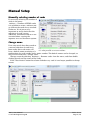
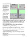
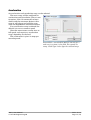
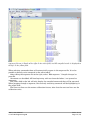
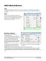
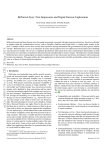
— The bright side of industry automation SMCP User Manual 2000-2010 OLTOM Engineering AB Email: [email protected] Revision 1.9.1 SMCP User Manual © OLTOM Engineering AB 2010-11-08 Page 1 (21) Table of Contents Introduction.................................................................................................................................... 3 SMCP Summary............................................................................................................................. 4 Getting Started............................................................................................................................... 5 Usage with Attached Card(s).....................................................................................................5 Usage with No Attached Card...................................................................................................6 Selecting Communications Port.....................................................................................................7 Autosearch for cards................................................................................................................... 7 Manual Setup.................................................................................................................................. 8 Manually selecting number of cards..........................................................................................8 Change name.............................................................................................................................. 8 Manual Address Selection......................................................................................................... 9 Card Addressing and Routing........................................................................................................9 Calibration factors........................................................................................................................ 11 Motor selection check boxes..........................................................................................................11 Acceleration.............................................................................................................................. 12 Creating a Sequence File..............................................................................................................13 Sequence File Reference...............................................................................................................15 Move.......................................................................................................................................... 15 Speed......................................................................................................................................... 15 Ramp......................................................................................................................................... 15 Reset......................................................................................................................................... 15 Go.............................................................................................................................................. 15 Wait.......................................................................................................................................... 16 StopMotion............................................................................................................................... 16 Current..................................................................................................................................... 16 StartSynch................................................................................................................................ 16 Sequence File Examples............................................................................................................... 17 Sequence with Default Names.................................................................................................17 Sequence with Calibration and Names...................................................................................18 Sequence File Example............................................................................................................19 SMCP Menu Reference.................................................................................................................20 Save........................................................................................................................................... 20 Open.......................................................................................................................................... 20 Running a sequence.................................................................................................................20 Disclaimer..................................................................................................................................... 21 SMCP User Manual © OLTOM Engineering AB 2010-11-08 Page 2 (21) Introduction The OLTOM Stepper Motor Controller Program (SMCP) is the perfect tool for process or lab automation. SMCP makes it possible to control motors in two ways: Either with immediate action or by saving a desired motion sequence and replaying the sequence. The sequence can be replayed an infinite number of times, as an ongoing process, or only once. The full version of SMCP can simultaneously control several OLTOM cards. (The SMCP LE edition can only control one card.) If the cards are linked via an I2C bus, a maximum of five cards can be controlled simultaneously. For example, using the PMW3 card with two separate motor driver per card, a total number of 10 stepper motors can be controlled from one computer and one single RS-232 or USB port. Synchronized motion between selected motors are possible. Commands are sent from SMCP to the cards, using short packets with error detection and recovery through packet retransmission. This provides reliable communication between the computer and the cards, as well as between the cards. The motor drivers can operate with various winding currents, controlled by software. Be sure to read the cooling specification for each PWM card. The RS232 communication runs at 115.2 bits per second. The I2C bus runs in multi-master mode standard at 100 kilobits per second, if used. Thus it is possible to connect the PMW cards to an existing I2C system. Also, embedded systems can control the cards directly using the I2C bus. If desired, a host computer or micro-controller can be directly connected to the I2C bus, with no RS232 hardware. This enables extremely compact systems. SMCP User Manual © OLTOM Engineering AB 2010-11-08 Page 3 (21) SMCP Summary ● Easy to use with an intuitive point and click user interface. ● Automatic card detection: SMCP can automatically find all attached OLTOM cards. ● Manual setup: If automatic detection is not used, select any number of cards (1-5) and manually assign any address. ● Point and click to control the stepper motors. ● Name the motors in the program to match your process or laboratory setup, for example as Axis2, insertion rod, etcetera. ● Every motor can be synchronized with any selection of connected motors. ● Every command, including movement and setup such as winding current and names, can be saved in a sequence file that can be rerun any time. ● Create sequences by point-and-click trial: Move the motor and if the motion is correct, save the motion to a sequence by a simple click. ● Single step through sequences to verify that the system behaves as expected. When stepping, each command being executed is highlighted. ● Break and stop a running sequence at any point. ● Sequences are stored as plain text files: Use the built-in editor or any other text editor to manually edit sequence files. ● Calibrate individual motor movement with desired units: Instead of steps SMCP can be set to count in actual millimeters, inches, radians, degrees, turns or any other desired unit. ● Calibrate motor speed. In the same way as movement, SMCP can be calibrated to use any desired unit, such as meters per second instead of steps per second. ● SMCP can be run without any hardware attached, for creating or editing sequences. SMCP User Manual © OLTOM Engineering AB 2010-11-08 Page 4 (21) Getting Started There are two modes for the OLTOM SMCP program to be in: either with card(s) attached, or without. With no hardware attached it is still possible to use the program and write sequences and choose card configurations. Usage with Attached Card(s) If there are one or more hardware cards attached to the computer do the following: 1. From the menu choose Settings--"Autosearch for cards". Enter the communication port the card is attached to. The program finds the attached cards and shows symbolic pictures of them. All addresses are automatically set to the correct values by the program. 2. Decide what names the different motors should have. Select the Settings--"Rename cards" menu to enable editing motor names. After a "New motion" form have been loaded the ability to change names on motors will be disabled. To change a name double click the default name for the motor, located just above the blue picture of the motor. 3. Click the "Calibrate" button to calibrate each motor. By doing this you can change the units used. For example, the program can be set to move 2 mm instead of 241 steps, or 2 turns instead of 879 steps. Only fill in the number of steps each of the desired unit corresponds to, and the desired unit itself. SMCP will then translate between user friendly units and step. 4. Select the Summary sequence menu. A summary of the data in the system so far displays. It is still possible to change the settings described above, but they will not be rewritten automatically to this summary. What is actually visible in the summary sequence form is the sequence file and the main settings for the system. This can be edited in any text editor. To have SMCP recognize changes, choose the "Compile" or press F9. Do not change the system settings, unless you understand the meaning of all parameters. 5. Select actions that the motor(s) should perform. There are two buttons: Execute command and Save command With the "Execute command" the selected command will be immediately executed. With the "Save command" button the command will be saved in the summary sequence file. By combining these two buttons it is possible to first test run each command, with appropriate changes, before saving the final version of the command to the sequence. 6. To run or step, the sequence of commands, choose "Compile changes" from the menu. Compile changes has to be executed before Run, every time a sequence has been changed or edited. Compile changes also saves the sequence to file. 7. If the sequence should be repeated infinitely, choose "Loop sequence" in the menu. This menu selection will then be checked. 8. When finished creating a sequence the sequence can be run, or saved to a file. If the same sequence should be used at a later point in time, only open the file and choose "Run". Everything, including COM port selection will be present since all the information is stored in the file. SMCP User Manual © OLTOM Engineering AB 2010-11-08 Page 5 (21) Usage with No Attached Card If no system is attached to the computer, then you should do the following first: 1. Choose the correct communication port by selecting Settings--"Communication settings" from the menu. This is not absolutely necessary to do right now, but a communication port has to be selected before running the sequence. 2. Choose the number of cards that will be used. Do this with Settings--"Number of xx cards" in the menu. 3. Set the correct address in software that corresponds to the address of the card in the hardware. Pressing the "New motion" button on the card shows you the motor form where this can be done. On the bottom of the settings form that is now visible, an option button field where the address should be set for each motor can be found. 4. Enter sequences like you would with a card attached. The only difference is that commands cannot be tried with Execute before being saved to the sequence. SMCP User Manual © OLTOM Engineering AB 2010-11-08 Page 6 (21) Selecting Communications Port For communicating with OLTOM cards, SMCP has to be told the port the card(s) are attached to. Select this communication port when prompted for this by the program. Standard serial RS232 ports are usually numbered 1 or 2. If a USB to RS232 converter is used, the port number is usually higher, 5 or higher. There are two ways selecting a port. One is by clicking in the menu on "Settings-Communication settings". The other one is to click on "Settings"-"Autosearch for cards". In both these cases you will be prompted to select a communication port. Illustration 1: To set the communications port, either If a sequence is saved, the port select Autosearch for cards, or Communications number will be saved with the sequence file and the same port will settings. automatically be opened when the sequence file is reopened. Autosearch for cards By clicking in the menu on Settings--Autosearch SMCP finds every attached card on the specified communication port. All the card addresses and the setting for the attached cards are configured automatically. Note that if a sequence file is opened after this action the settings from this file will be used instead. Illustration 2: Select Autosearch to find cards automatically SMCP User Manual © OLTOM Engineering AB 2010-11-08 Page 7 (21) Manual Setup Manually selecting number of cards By manually selecting the number of cards in the menu settings--Number of PWM3 cards it is possible to create a software setup without the need of any attached hardware. It's of course very important to really check that the selections of cards, names, addresses, movements and so on are accurate before running the sequence on a real hardware system. Change name If an auto search have been made or a manual selection of cards have Illustration 3: Select number of cards. From this menu been made, then each motor will it is also possible to rename motors. have a default name consisting of a combination of a card number and a motor number. The default names can be changed, as long as each motor has a unique name. Change names by selecting Settings--Rename cards from the menu, and then double clicking directly on the names of the cards. If the "New motion" button have been clicked on any card it is no longer possible to change names. Illustration 4: Double-click the motor name to change it SMCP User Manual © OLTOM Engineering AB 2010-11-08 Page 8 (21) Manual Address Selection Card addressing must be fully understood if several cards are connected on an I2C-bus. Read Card Address and Routing below, the card data sheet, and the OLTOM Card Driver Programming Reference for more detailed information. Fortunately, SMCP hides most of the addressing complexity from the user. If the cards have been correctly configured and connected, all that has to be done in SMCP is to select Settings--Autosearch for cards from the menu. In most cases this will be enough. If Autosearch is not used, is is easy to manually change address the address for a card: Click on the option button for the dip Illustration 5: To manually set card addresses, make sure the switch, so that it matches DIP switch settings on the physical card matches the DIP switch the physical card. settings in SMCP. Note that for cards with two or more controllers per card, the addresses for all controllers on the card will change when any one is changed. A special case is the Ret address selection. Ret addresses the card RS232 port. Thus instead of routing it to a motor the commands or messages will be sent out on to the RS232 port. This feature is used for some OEM versions of the cards, if data is needed for feed back, and control of third party devices. If hardware address selection is incorrect when creating a sequence file, a new correct address has to be entered in the editor at a later stage before running the sequence. Card Addressing and Routing All communication in the between the cards and the host system is by packets; much like the Internet TCP/IP protocol. Each OLTOM card does packet routing, selecting which way to forward a packet not addressed to one of the controllers or devices on the card. For example, a PWM3 card with two motor controllers per card, one RS232, and one I2C port can deliver a packet four ways, depending on the destination address in the packet: The packet can go to motor 1, motor 2, out of the cards own RS232 port, or out on the I2C-bus. To send packets, the SMCP program requires three numbers: •The address of the destination device, for example a motor controller on an OLTOM PWM card. •The address of the port on the OLTOM card that the computer is attached to. (Configured automatically by SMCP.) SMCP User Manual © OLTOM Engineering AB 2010-11-08 Page 9 (21) •The communication port on the computer. If the system auto searches for cards, and finds at least one card, all of the three addresses are set correctly. No manual change setup is needed. SMCP User Manual © OLTOM Engineering AB 2010-11-08 Page 10 (21) Calibration factors If the calibration factor is not changed, what is written in the text box during stepping motion will be interpreted as the number of steps to move the motor. In many applications it might be desirable to write the number of millimeter or turns the motor should move instead of the number of steps. The calibration function makes this possible. Click the calibration button. In the dialog box that appears, fill in the number of steps that corresponds to the unit you want. For instance: If a motion of one turn is desirable fill in 400 if this is the number of steps that is needed for one turn off your motor. In the unit text box fill in the word "Turns" and then click OK. For every stepping motion from now you only have to fill in how many turns the motor should move and not how many steps. This calibration information is saved in the file. Another example: If your motor is attached to a mechanical system that uses millimeters and 1 millimeter corresponds to 56 steps then write 56 in the factor text box and "mm" in the unit text box. Motor selection check boxes It is very easy to get motors running using the SMCP software. When the selected number of motors are visible on screen, click the New Motion at the motor that should get a motion. A new window appears. There are nine different basic motions that can be selected. In addition to this, four of them can get a synchronization added to the command. To use this window, put the radio button at the desired function. Add the value in the designated field. Press Execute command or Save Command depending on the desired function. These buttons are often used a in the way that the motion is first tested with the Execute button, and if the motion is the right one, push the save button for the tested and now selected motion. To get a synchronized motion the check-box called Synch. must be checked. A synchronization ID number must be added in the text-box above. To get the synchronized motion the Start selected sync. radio button must be used. When Execute command is pressed all motors with the same synchronization ID will act at the same time. Illustration 6: To create a sequence, select View sequence from the Edit sequence menu SMCP User Manual © OLTOM Engineering AB 2010-11-08 Page 11 (21) Acceleration An acceleration and retardation ramp can be selected. The same ramp, will be used both for acceleration and retardation. There is one exception, if the Go command has been chosen and the movement begins with a ramp it will always end without ramp when the StopMotion command executes. If no acceleration ramp is selected the default is to run at constant speed. Note that some motors cannot start at full speed, and require an acceleration ramp, depending on the load. The acceleration is given in steps per second squared. Illustration 7: Acceleration Ramps.Click Type 1 and zero is written in the field, this equals no ramp. Click Type 2 then type the selected ramp. SMCP User Manual © OLTOM Engineering AB 2010-11-08 Page 12 (21) Creating a Sequence File Select Edit Sequence, "View sequence" from the menu to create a sequence file. If the cards and addresses already have been configured, the addresses and ports will be seen at the beginning of the sequence file. If you any data is missing or wrong, click to close the sequence window, apply necessary changes, and then open the sequence window again. If sequence file has been saved, the changes will not appear in the window. Illustration 8: To create a sequence, select View In that case, manually edit the sequence from the Edit sequence menu sequence, and recompile by selecting "Compile" or press F9. In the example below the motors have been renamed to C1Y, C2Y, C1X, and C2X. After all the card settings are ready the summary sequence have been chosen. All the data below is automatically written to the file. SMCP User Manual © OLTOM Engineering AB 2010-11-08 Page 13 (21) Illustration 9: Example of sequence file for two motors, with different movement added. The sequence file text is shown to the right in the white field, and the compiled result is displayed to the left in the yellow field. When selecting commands these will automatically appear in the sequence file. It is also possible to directly write command in the edit window. After editing the sequence file to the right, select Edit sequence "Compile changes" or press F9. Comments can be added. All lines beginning with two forward slashes // are ignored as comments. The yellow field to the left will only display the compiled commands that will be executed. When stepping through a sequence, the currently executing command will be highlighting in the yellow field. The Next two lines are the motors calibration factors, after that the next two lines are the calibration units. SMCP User Manual © OLTOM Engineering AB 2010-11-08 Page 14 (21) Sequence File Reference The commands available in a sequence file are listed below. Move Syntax examples: Card1motor1:Move=400 Card1motor1:Move=400:SyncID=1 The move command tells a motor to move. Add the number of steps, or another value depending on the calibration factors. Speed Syntax examples: Card1motor1:Speed=400 Card1motor1:Speed=400:SyncID=1 The speed command tells the motor by which speed the motor should move. Add the number of steps per seconds, or another value depending on the calibration factors. Ramp Syntax example: Card1motor1:Ramp=100 The Ramp command tells you with what acceleration and retardation the motor will use. The value is steps per seconds squared. Thus how many steps per second the speed will increase every second. Reset Syntax example: Card1motor1:Reset=..to power on state This command will reset the whole card, not only one motor, to power on state. This will initiate that a Power On packet is sent. Go Syntax examples: Card1motor1:Go=+ Card1motor1:Go=400:SyncID=1 The Go command will make the motor go infinite. The only thing you need to add is a + or a sign to specify the direction of the motor. The motor will keep moving until a StopMotion command is sent. SMCP User Manual © OLTOM Engineering AB 2010-11-08 Page 15 (21) Wait Syntax example: Card1motor1:Wait=10 This is a driver and thus a operating system handled command. You specify for how many seconds the program should wait until next command is executed. You specify number of seconds, but the resolution does not guarantee any resolution better than seconds. StopMotion Syntax examples: Card1motor1:StopMotion Card1motor1:StopMotion:SyncID=1 No parameter is needed for this command. It will simply stop the motion. Note that no ramp will be used. Current Syntax example: Card1motor1:Current=0.8 This parameter sets the winding current for each motor. It is essential that this is set correctly since the wrong current can harm the stepper motor. StartSynch Syntax example: Card1motor1:StartSynch:SynchID=1 If a synchronized action is selected using this command will invoke the synchronized command. SMCP User Manual © OLTOM Engineering AB 2010-11-08 Page 16 (21) Sequence File Examples Sequence with Default Names The example below has the default motor names and no calibration factors. Version 1.0.2 NrOfCards=1 ComPort=6 Const Card1 motor 1=41 Const Card1 Motor 2=42 ComCard=40 CalibStep Card1 motor 1=1 CalibStep Card1 motor 1=1 CalibStepUnit Card1 motor 1= CalibStepUnit Card1 motor 1= CalibSpeed Card1 motor 1=1 CalibSpeed Card1 motor 1=1 CalibSpeedUnit Card1 motor 1= CalibSpeedUnit Card1 motor 1= Begin Card1 Card1 Card1 Card1 Card1 Card1 Card1 Card1 Card1 sequence motor 1:Reset motor 1:Current=0.6 motor 1:Speed=400 motor 1:Ramp=800 motor 1:Move=4000 motor 1:Wait=5 motor 1:Go=motor 1:Wait=4 motor 1:StopMotion SMCP User Manual © OLTOM Engineering AB 2010-11-08 Page 17 (21) Sequence with Calibration and Names The example below adds calibration factors, as well as more suitable names for the motors. Version 1.0.2 NrOfCards=1 ComPort=6 Const X-axis=41 Const Y-axis=42 ComCard=40 CalibStep X-axis=400 CalibStep Y-axis=10 CalibStepUnit X-axis=Turns CalibStepUnit Y-axis=mm CalibSpeed X-axis=400 CalibSpeed Y-axis=10 CalibSpeedUnit X-axis=Turns/s CalibSpeedUnit Y-axis=mm/s Begin sequence X-axis:Reset X-axis:Current=0.6 X-axis:Speed=2 X-axis:Ramp=800 X-axis:Move=10 X-axis:Wait=5 X-axis:Go=X-axis:Wait=4 X-axis:StopMotion SMCP User Manual © OLTOM Engineering AB 2010-11-08 Page 18 (21) Sequence File Example Illustration 10: Example of addresses set in a sequence file: Two cards are used. Motors are named C1X, C1Y, C2X and C2Y. They can be found on addresses 0x41, 0x42, 0x5D and 0x5E. The SMCP program is attached to the port address 0x5C. (In this case the communications port is on the same card as the motors C2X and C2Y.) The sequence file contents are displayed in the white field to the right. Never change the first two lines in the sequence file. They are necessary for compiling of the program. The next line tells the program what communication port is to be used. The next four lines declare the motors names and what hex addresses they correspond to. In this case the motors have been renamed to C1X, C1Y, C2X and C2Y. For each motor controller in the system there will be one line here. The next line is ComCard = 5C. This is the address of the RS232 port of the card that the computer is attached to, if this is not correct set the program will not work. Be very careful when manually changing address lines. SMCP User Manual © OLTOM Engineering AB 2010-11-08 Page 19 (21) SMCP Menu Reference Save To save the created file, choose File--Save file in the menu. It's possible to save files in *.seq format. This format is a plain text format and the file can also be opened for editing in a text editor. Open To open an existing file chose open in the menu. Any file opened before will be erased. If the file that was opened before has not been saved you will be prompted to do so. It's possible to open *.seq files. Illustration 11: Opening a sequence file Running a sequence There are two ways of running a created sequence. The Step function is often preferred to begin with. By clicking on Step in the menu, or pushing the F2 key, each command will be executed one at a time. This is very useful when checking if all the motions are correct, since the pace of the motion is easily controlled this way. Illustration 12: Illustration 10: Select Step sequence The other way to run the sequence is to single step through a sequence for debugging or to choose Run. This will execute the verification whole sequence. The sequence can be stopped while running by using the Stop function in the menu selection. When stepping or running through a sequence it is possible to see each step that is being executed in the yellow part of the sequence file window, if this window is open and visible. By checking the Loop sequence the sequence will start from beginning when it reaches the end. SMCP User Manual © OLTOM Engineering AB 2010-11-08 Page 20 (21) Disclaimer We believe that the information contained herein was accurate in all respects at the time of printing. OLTOM Engineering AB cannot, however, assume any responsibility for errors or omissions in this text. Also note that the information in this document is subject to change without notice and should not be construed as a commitment by OLTOM Engineering AB. SMCP User Manual © OLTOM Engineering AB 2010-11-08 Page 21 (21)