1
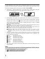
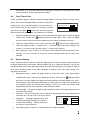
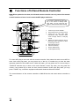
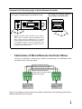
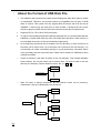
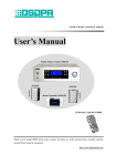
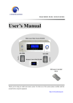
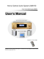
Home Central Audio System AM8150
Home Central Audio System AM8150
User’s Manual
Home Central Audio System AM8150
AUX518
Room Controller BM815R
Sound Box Series
Sound Box Series
AUX518
IR Remote Controller FM808
Welcome to use the central audio system. For better use of this equipment, please read this
manual thoroughly before use.
Contents
※ General Description ............................................................................................................................... 1
1.About the Central Audio System .................................................................................................. 1
2.Functional Characteristics of System Host................................................................................. 1
※ Appearance and Functions of Host Device ........................................................................................ 2
1.Functions of Front Panel ............................................................................................................... 2
2.Functions of Back Panel ............................................................................................................... 4
※ Connection Instructions ......................................................................................................................... 1
1.Schematics of Input Connection .................................................................................................. 1
2.Connection Schematics for Tuner Module ................................................................................. 1
3. Connection Schematics for Infrared Learning Transmitter and Central Controller ................ 3
4.Connection Schematics for Zone 1 Output ................................................................................ 3
5.Connection Schematics for Other Zone Output......................................................................... 5
※ Operating Instructions for Host............................................................................................................. 6
1.Power On State............................................................................................................................... 6
2.Operating Instructions for Manual Control of Zone 2-12 .......................................................... 6
3.Operating Instructions for Manual Control of Zone 1................................................................ 7
4.Instructions for Manual Operation of MP3 Player ................................................................... 10
4.1 Mode Selection................................................................................................................ 10
4.2
Time Display .................................................................................................................... 10
4.3 Music Selection ............................................................................................................... 10
5.Instructions for Manual Operation of Tuner.............................................................................. 10
5.1 Band Selection .................................................................................................................11
5.2 Search Radio ....................................................................................................................11
5.3 Store Radio .......................................................................................................................11
5.4 Mute Mode ........................................................................................................................11
5.5 Load Radio Frequency....................................................................................................11
6.Timer Programming ..................................................................................................................... 12
6.1
Timer Setting.................................................................................................................... 12
6.2
Time Calibration .............................................................................................................. 15
6.3 Infrared Learning ............................................................................................................. 15
6.4 Copy Timer Point............................................................................................................. 16
6.5 System Setting ................................................................................................................ 16
※ Functions of Infrared Remote Controller........................................................................................... 17
※ Fabrication of Wired Remote Controller Wires ................................................................................ 18
※ About the Format of USB Disk File.................................................................................................... 19
※ Packing List ........................................................................................................................................... 22
※ Performance Specifications ................................................................................................................ 23
1.MP3 Player.................................................................................................................................... 23
2.AM/FM Tuner ................................................................................................................................ 23
3.Timer .............................................................................................................................................. 23
4.General Index ............................................................................................................................... 24
*
*
※
Central Audio System
General Description
1.About the Central Audio System
The AM8150 is a set of modern central audio system to your desire.
Except all the functions of the traditional family audio systems, this system is also provided with: 1)
Timer function, that is, preset the specific time and the task to be executed at that time. 2) The
function that different rooms can hear different music at the same time. This system has
another important function. That is, you can control the working status of the host from the room.
For example, from the remote controller installed in the room, you may select the program played
by the host, or control the volume and tone for your room.
The control host of this system has integrated the functions of MP3 player, radio, zone divider,
timer and pre / post amplifier. It is provided with DVD, PC, TV and AUX input ports for peripheral
audio equipment, and line audio signal output port for zone 1 and 2. There are 12 zones, among
which the 1st zone is of 5.1 channel and the others are of dual channel. The 5.1 channel is
available with two input modes, i.e. line input and fiber optical input. There are 12 remote control
data interfaces connected to the wired remote controllers for 12 zones, so that the host and remote
controller set up an interactive dual-way control, providing high convenience for the users.
2.Functional Characteristics of System Host
l
l
l
l
l
l
l
l
l
Modern central audio system with plentiful functions.
There are 12 zones, among which the 1st zone is of 5.1 channel (Front Left, Front Right,
Rear Left, Rear Right, Center and SW) and the others are of dual channel.
The 1st zone has 5.1 channel (Front Left, Front Right, Rear Left, Rear Right and Center; SW
without PA but output from the line), with each channel having 60W output power. The 2nd
and 3rd zones have 2 x 60W output powers, and the 4th ~ 12th zones have 2x20W output
power.
The 1st zone is provided with 5.1 channel line input and fiber optical input function, as well as
Dolby and DTS decoding functions. DSP surround processing function is provided, and
different sound field effects are available for selection.
AM/FM radio function is provided. This function is realized in form of modular design, and
can be separated from the host for installation at a position with better receiving effect. The
module is connected to the host via T568A network cable.
MP3 play function and USB port are provided. Support the music files of MP3 format stored
in USB disc, MP3 player, mobile HDD, card reader and other storage devices.
Provided with DVD audio input port, PC audio input port, TV audio input port and one
auxiliary audio input port. Also provided with line audio signal output port for zone 1 & 2,
DVD/TV video input port and 12-zone video output port.
Timer control function provided. The user may edit 100 timing points. With one week as a
cycle, it is possible to execute timer control over the ON/OFF switching, audio source,
volume, clock, AM/FM radio, MP3 play and output power ON/OFF for 12 zones.
One AC220V power socket provided, with its switching state interlinked to the switch of zone.
AM8150
1
*
*
l
l
l
l
Central Audio System
You may switch on any of the zones to switch on this power output. This power output is
switched off when all the zones are switched off. Timer control over its switching state is
provided.
Infrared learning function provided, so that it can learn the remote controller of any brand.
RS232 remote control port provided, so that the user may control the functions of this device
via central control equipment.
Inductive touch keys are designed for the panel, with two control modes available, i.e. local
control and remote control.
Video switching function provided. The video is switched in synchronization with the audio
input.
※ Appearance and Functions of Host Device
1.Functions of Front Panel
1)
2)
3)
Power Switch (POWER)
Press this key to switch on the power
and release it to switch off the power.
Power Indicator (POWER)
This indicator is bright when the power
is switched on. And it is dark when the
power is switched off. This indicator is
red under standby state and turns green
under working state.
Zone ON/OFF Key
① Execute ON/OFF control to the
zone directly from main interface.
② Return to main interface from any of
2
4)
Level I menu.
Key for Moving Cursor / Quick
Search of Radio Station
This is a multifunctional key:
① It is generally used to move the
cursor forward or load the options
for selection. In some operations, it
is equivalent to a digital wheel
rotating counterclockwise.
② Under radio working state, it can be
used to search the radio station
from high frequency to low
frequency and will be stopped
AM8150
*
*
5)
Central Audio System
automatically when searching a
station.
Key for Moving Cursor / Quick
Search of Radio Station
This is a multifunctional key:
1
① It is generally used to move the
cursor backward or load the options
for selection. In some operations, it
is equivalent to a digital wheel
rotating clockwise.
6)
7)
8)
② Under radio working state, it can be
used to search the radio station
from low frequency to high
frequency and will be stopped
automatically when searching a
station.
Enter / Confirm Key (SELECT)
Enter the setting interface or confirm the
operating result. In some operations, it
is equivalent to a digital wheel.
LCD Screen
Display the functions and state of the
equipment.
Operation Option Control Key
(TIMER)
Enter the operation option interface.
This interface includes such operation
options as the timer setting, time
calibration, infrared learning, timer copy
and system setting. The interface is as
shown below:
Operation Options
9)
zones. It can also used to enter the
standby interface (time interface) from
main interface. The main interface is
below:
TIMER SET
ADJ TIME
IR SETUP
COPY TIMER
SYSTEM SET
EXIT
Key for Controlling MP3 (MP3)
Enter MP3 setting interface.
10) Key for Controlling Tuner (TUNER)
Enter tuner setting interface.
11) Key for Displaying Zone State
(ZONE)
Press this key to enter the main
interface that displays the state of 12
PC
4 TV
2 DVD
3 TUNER
5
6
MP3
PC
12) Multifunctional Digital Wheel
① Used to search the radio frequency
under tuner mode.
② Used to search the program under
MP3 mode, and select and confirm
the play mode.
③ Used to direct the options, select
the desired options and confirm the
result of current operation under
timer mode.
④ Used to direct the options under
zone control mode and enter the
zone control interface; also used to
perform operations and confirm the
result of current operation.
13) Infrared Window (IR)
14) USB Port (USB)
Used for inserting USB disk, mobile
HDD or card reader.
15) Key for Switching Tuner AM/FM Band
(BAND)
16) Key for Radio Storage (MEMO)
17) MONO/
This is a multifunctional key:
① Under tuner state, it serves as a key
for switching between mono /
stereo.
② Play / stop key under MP3 state.
Key
18)
This is a multifunctional key:
① Mute key under tuner state.
② Play / Pause key under MP3 state.
19)
Key
This is a multifunctional key:
① A key for searching the radio station
forward under tuner state.
AM8150
3
*
*
Central Audio System
② A key for searching the desired
program forward under MP3 state.
20)
Key
This is a multifunctional key:
backward under tuner state.
② A key for searching the desired
program backward under MP3
state.
① A key for searching the radio station
Forced Switching of Key Functions
The function keys on the host panel can be forcibly switched of their functions under Level I menu
(interface). For example, you may touch MP3 key on the panel under tuner state interface, so that
the screen will change from display of tuner state to MP3 state, in which case you can operate
MP3 state. You may touch TIMER to enter operation option interface, touch ZONE or zone
ON/OFF key to enter the zone state display (main interface of equipment system). The interface
that can be directly switched is as shown below:
1
PC
2 DVD
AM/FM PLAYER
3 TUNER
BAND FM
4 TV
5
MP3
6
PC
03 \ 01
PLAY ALL
03:57 04:15
Override category. Please wait…
CH 40
100.45MHz
MP3 PLAYER
LOOP
SIGN
STEREO
OPTION
TIMER SET
复制定时
COPY
TIMER
ADJ TIME 红外学习
IR SETUP
调校时间
系统设置
SYSTEM SET
退 EXIT
出
2.Functions of Back Panel
1)
4
Optical Input Port for 5.1 Channel
(OPTICAL INPUT)
For connection and description, please
refer to the Connection Instructions (on
AM8150
*
*
2)
3)
4)
5)
6)
7)
8)
9)
page 5).
Tuner Mode (Page 5)
The tuner function is realized in form of
modular design, and can be separated
from the host for installation at a
position with better receiving effect. The
module is connected to the host via
T568A network cable.
Tuner Module Port (TUNER INPUT)
For connecting the tuner module signal.
DVD/TV Video Input Port (VIDEO
INPUT DVD) Page 5
Wired Remote Controller Port for Zone
1 ~ 12
(REMOTE INPUT) Page 8 and 9
Zone 1 PA Output Port (ZONE1
SPEAKER OUTPUT) (Page 7)
Zone 2/Zone 3 PA Output Port (Page 9)
(ZONE2/ZONE3 SPEAKER OUTPUT)
AC220V Timer Power Output Socket
(TIMER)
The switching state of timer power
output socket is interlinked to the switch
of zone. You may switch on any of the
zones to switch on this power output.
This power output is switched off when
all the zones are switched off. Timer
control over its switching state is
provided. (Page 15)
RS232 Port (RS232)
Central Audio System
page 5).
12) DVD/PC/TV/AUX Audio Input Port
13) Line Signal Output Port for Zone 1 /
Zone 2
14) 5.1 Channel Sub Woofer Output for
Zone 1
(SUB WOOFER) (Page 7)
This signal has no PA and it is output
via line directly.
15) Zone 1 ~ 12 Video Output Port (Page 8)
For transmitting the DVD/TV video
signals to 12 zones, with its distribution
changing synchronously with the audio
signal.
16) Zone 4 ~ 12 PA Output Port (Page 9)
17) AC220V Working Power Input
RS232 remote control port is provided,
so that the user may control the
functions of this device via central
control equipment.
10) Remote Control Output Port (REMOTE
OUT) Page 7
Connected to infrared receiver for
infrared learning of the function controls
over external DVD and TV.
11) 5.1 Channel Input Port for Zone 1 (5.1
INPUT)
For connection and description, please
refer to the Connection Instructions (on
AM8150
2
※
Connection Instructions
1.Schematics of Input Connection
DVD Video Signal
RS232 IN
Optical
TV Video Signal
5.1 Channel
Signal
Stereo Signal
DVD Player
PC
Other Audio Sources
TV
Notes :
l The 5.1 channel input and optical input on DVD player provide audio
signal to zone 1 only. When connecting the optical port, please
remove the dustproof cap as directed. Please keep the dustproof
cap properly. To keep the optical port clean, please cover up the
dustproof cap when this port is long put out of use.
l The video signals input from DVD and TV are transmitted to 12 zones
respectively via 12 video output ports on this device.
l Except optical input, the other inputs above are connected by using
lotus connector.
Optical Port
Lotus Connector
2.Connection Schematics for Tuner Module
The tuner function is realized in form of modular design, and can be separated from the host for
installation at a position with better receiving effect. Installation of the tuner module on a better
place can improve the receiving effect. The tuner module is connected to the host via T586A
network cable. Even the module is installed on the host, it can also be connected to the back panel
on this device.
Notes: To separate the tuner module from this device, the extension wire, if needed, shall
be fabricated as follows:
RJ45 Port
Pin 1
The colors from left to right are:
Green white, green, orange white,
blue, Blue white, orange, brown
white and brown. The two ends
Spring clamp
match each other.
against you
The tuner connection is as shown below:
Connection of tuner module to this device:
FM antenna
AM antenna
Press
down
将夹线盖
clamp
按下 cover
Insert将连接线 the
connection
插入线孔 wire
into the wire hole
Loosen
the
将夹线盖
clamp
cover
松开
TUNER OUT
TUNER INPUT
FM antenna
Connection of tuner module for not installation on this device:
AM antenna
2
3. Connection Schematics for
Transmitter and Central Controller
DVD player
Infrared
Learning
Central Control Device
TV
The
transmitter connected
to REMOTE
port on the infrared
红外遥控输出的
REMOTE
OUT1OUT1
接口连接的发射器对
remote controller corresponds to external DVD player; the
应外接的 DVD 播放器,REMOTE OUT2 接口连接的发
transmitted connected to REMOTE OUT2 corresponds to TV.
射器对应外接的电视机。
4.Connection Schematics for Zone 1 Output
Connection Schematics for 5.1 Channel Output
Host Device
+
-
+
-
-
+
+
-
+
-
Center
Left
Right
Surround
Left
Right
Front
3
Sub Woofer
Placement Schematics for 5.1 Sound Box
① Center
② Front Left
③ Front Right
④ Rear Left Surround
⑤ Rear Right Surround
⑥ Sub Woofer
The PA output power of
each channel ①-⑤ is 60W
Line signal output from ⑥
channel
Integrated Connection Schematics for Zone 1 Output
Wired Remote Controller
Infrared remote controller
5.1 Channel
Line audio signal
① Center
5.1 Channel
② Front Left
③ Front Right
④ Rear Left Surround
⑤ Rear Right Surround
⑥ Sub Woofer
TV
4
5.Connection Schematics for Other Zone Output
Connection schematics for Zone 2 and Zone 3 output: The zone 2 and zone 3 are of stereo
dual-channel output, with each channel at 60W. The zone 2 has two groups of ports, and the
signals are output in parallel. You may connect one of them, or connect two sound boxes at the
same time. Take care that the total resistance shall not be lower than 4Ω.
Zone
2
can also
be
connected
like this
Zone 2
can
be
connecte
d like this
Zone 2 Sound Box
Zone 3 Sound Box
Zone 2 Sound Box
Zone 3 Sound Box
Integrated connection schematics for other zones: The zone 4 ~ zone 12 of this device are of
stereo dual-channel output, with each channel at 20W.
One zone corresponds to one video output
Zone 1 TV
Zone 12 TV
Zone 1
Zone 12
HiFi PA
Zone 2 Line Output
5
Zone 4 Sound Box
Zone 12 Sound Box
※
Operating Instructions for Host
1.Power On State
Connect all the wires correctly and check for no error. Then, connect the power supply. Press
down Power On/Off key to switch on the device. If there is no zone opened, the system will be
under standby state and display the standby interface on the screen (Fig. 1-1). The power indicator
is red. In this case, the timer power output is off. Under standby state, you may press ON/OFF key
or ZONE key to enter the main interface (Fig. 1-2). After a zone is opened, the current state of
switching, audio source and volume in this zone will be immediately displayed. In this case, the
power indicator will be green, while the timer power output will be opened. (Note: If all the zones
are closed, the timer power output will also be closed. If one of the zones is opened, the timer
power output will be automatically opened).
2010 / 03 / 05
MON.
POWER OFF
8:35:16
ON/OFF key
1
PC
4 TV
2 DVD
3 TUNER
5
6
MP3
PC
NEXT TIMER POINT∶TUES.07:55:00
(Fig. 1-2)
(Fig. 1-1)
2.Operating Instructions for Manual Control of Zone 2-12
The control of zone 2 ~ 12 includes the selection of audio source, adjustment of volume and tone,
and testing of clock sound for each zone. The operating procedures are as follows:
Notes
In the operations marked * below, the functions for rotating the digital wheel can also be done by using
the key
. In the operations marked #, the functions for pressing the digital wheel can also
be done by using the key
Ø
Ø
.
Enter Zone Operation Interface
Under the main interface, rotate the digital wheel * to
select a zone (Fig. 2-1) and press digital wheel once # to enter the zone operation interface
(Fig. 2-2). Under this interface, you may carry out the above operations to the opened
zones.
Select Audio Source
There are two ways for selecting the audio source:
① From zone operation interface, rotate the digital wheel * to move the cursor to pane behind
the “Program” (Note: The cursor herein refers to the dark grey icon when an option is
selected). Press the digital wheel # once, so that the icon
will appear behind the pane.
Rotate the digital wheel * to display the 6 types of audio source in turn. When the desired
audio source is on display, stop rotating the digital wheel and press the digital wheel #
again, so that the selected audio source will be allocated to this zone.
② Select the audio source from remote controller. You may select by directly pressing the
source name key or SOURCE+/SOURCE- key on the remote controller.
6
Ø
Volume / Tone Control
There are two ways for controlling the volume and tone:
① From zone control interface, you may rotate the digital wheel * to move the cursor to the
sliding pane behind the "Volume" option. Press the digital wheel # once, so that the icon
will appear behind the pane. Then, rotate the digital wheel * clockwise or counterclockwise
to move the slider left and right, so that the zone volume will be increased or decreased
accordingly. Adjust the treble or bass tone in the same way.
②Use the wired remote controller or infrared remote controller to control the zone volume /
Ø
Ø
tone under the interface except “Operation Option”. For control of the zone volume / tone
from wired remote controller, please refer to the Operating Instructions for BM815R (Wired
Remote Controller).
Ringer Testing
Rotate the digital wheel * to move the cursor to “Ringer Testing” option and
press the digital wheel # once, so that a set of ringers will be output from the output port.
(Note: The remote controller does not provide the “Ringer Testing” function)
After completion of the above operations, rotate the digital wheel * to move the cursor to
“CONFIRM” checkbox. Then, press the digital wheel # once to confirm and exit. The other
zones from zone 2 to 12 may be controlled according to the method above.
1
PC
2 DVD
3 TUNER
Press digital wheel
ZONE 02 CONTROL
SOUR.
4 TV
5
MP3
6
VOL.
DVD
BASS
PC
TREB.
Or press
CHIME TE.
OK
(Fig. 2-2)
(Fig. 2-1)
3.Operating Instructions for Manual Control of Zone 1
Zone 1 is different from other zones. Except the 6 audio sources in other zones, the zone 1 also
has 5.1 channel and optical input source, totaled 8 types of audio sources for selection. Meanwhile,
it differs from other zones in view of zone output mode ad tone / volume control. The detailed
operations are as follows:
Under the main interface, rotate the digital wheel * to move the cursor to zone 1 state pane (Fig.
3-1). Then, press the digital wheel # once to enter the zone 1 control (hall control) interface (Fig.
3-2).
1
PC
2 DVD
3 TUNER
Press digital wheel
HALL CONTROL
SOUR.
4 TV
5
MP3
6
PC
Or press
(Fig. 3-1)
1)
2)
7
DVD
VOL.& TONE
SPK. SETUP
SEPA. VOL.
MODE SETUP
OK
(Fig. 3-2)
Select Audio Source
The selection of audio source for zone 1 is same as that for other
zones. The only difference is that the zone 1 has two more options, i.e. 5.1 channel (5.1LINE)
and optical (OPTICAL) source. Except that the 5.1 channel (5.1LINE) and optical (OPTICAL)
can be manually selected from the host panel, they can also be selected by pressing the
SOURCE+/SOURCE- on infrared remote controller.
Total Volume / Tone
Rotate the digital wheel * to move the cursor to “Total Volume/Tone”
option and press the digital wheel # once to enter “Hall Total Volume / Tone Control" interface
(Fig. 3-3), where you can control the total volume and tone of zone 1 (hall) and carry out ringer
testing. For control of the volume and tone, please refer to the Operating Methods for Control
of Zone 2~12 Volume and Tone. It will not be repeated here.
Press digital wheel
HALL CONTROL
SOUR.
DVD
VOL. & TONE
SPK. SETUP
SEPA. VOL.
MODE SETUP
OK
HALL VOL. AND TONE CONTROL
TREB.
VOL.
BASS
CHIME TE.
Or press
OK
(Fig. 3-3)
(Fig. 3-2)
3)Speaker Setting
Rotate the digital wheel * to move the cursor to “Speaker Setting” option and
press the digital wheel # once to enter the “Hall Speaker Setting” interface (Fig. 3-4) (Next
page). Among the setting options:
Ø Testing: Used for testing if the speakers work normally. The “Normal” option refers to the
current program being played. Then, exit the test state.
Ø Front: It is provided with two options, i.e. Big and Small, used for setting big sound box or
small sound box.
Ø Center: It is provided with three options, i.e. Big, Small and None. Except for setting the big
sound box or small sound box, it is also used for setting the center signal YES or No under
AUTO and Dolby Pro mode. If setting to “No”, the center signal is distributed to the two
loudspeakers on left and right.
Ø Surround: It is provided with three options, i.e. Big, Small and None. Except for setting the big
sound box or small sound box, it is also used for setting the surround signal YES or No under
AUTO and Dolby Pro mode. If setting to “No”, the surround signal is canceled.
HALL CONTROL
SOUR.
HALL SPEAKER SETUP
Press digital wheel
VOL. & TONE
TEST
NORMAL
FRON.
LARGE
SPK. SETUP
SEPA. VOL.
CENT.
LARGE
SURR.
LARGE
MODE SETUP
OK
WOOF.
HAVE
DVD
Or press
OK
(Fig. 3-4)
(Fig. 3-2)
Ø
Sub Woofer: It is provided for setting sub woofer signal YES or No under AUTO and Dolby Pro
mode. If setting to “No”, the sub woofer signal is distributed to the two loudspeakers on left
and right.
Ø
The above settings can be done by using the digital wheel, or by using the key
and
. After setting, press “Confirm” to confirm and exit the setting interface.
4)Independent Volume
Rotate the digital wheel * to move the cursor to “Independent Volume"
option and press the digital wheel # once to enter the “Hall Independent Volume Control”
interface (Fig. 3-5).
Press digital wheel
HALL CONTROL
HALL SEPARATE VOLUME CONTROL
VOL. & TONE
FRON.
CENT.
SPK. SETUP
SEPA. VOL.
SURR.
WOOF.
MODE SETUP
OK
SOUR.
DVD
(Fig. 3-2)
Or press
OK
(Fig. 3-5)
8
The hall independent volume control refers to independent control over the volume of several
channels, e.g. front and surround. The operation is same as that for zone volume control. It may
be done by using digital wheel or by using the keys
and
.
5) Mode Setting
Rotate the digital wheel * to move the cursor to “Mode Setting” option and
press the digital wheel # once to enter the “Mode Setting” interface (Fig. 3-6).
Press digital wheel
HALL CONTROL
SOUR.
DVD
VOL. & TONE
SPK. SETUP
SEPA. VOL.
MODE SETUP
OK
(Fig. 3-2)
Ø
Ø
DSP EFFECT
Or press
AUTO
LIVE
OK
(Fig. 3-6)
Listening Mode: Three options are provided, namely: AUTO, Dolby Pro Logic and STEREO.
Rotate the digital wheel to move the cursor to the pane behind "Listening Mode”, and press
the digital wheel. When the icon
Ø
HALL SOUND FIELD MODE
LISTEN MODE
appears in pane, rotate the digital wheel to adjust the
option. Select the desired option and press the digital wheel again to confirm. The effect
under three modes is respectively:
① STEREO: Forcibly there is output from the speakers on front left and front right only, but no
signal output from other channels. It is effective for all program types.
② AUTO:Auto mode. If the input is Dolby digital AC-3, the listening mode will be AC-3
DIGITAL. If the input is DTS, the listening mode will be DTS DIGITAL.
③ Dolby Pro Logia: Dolby Pro Logic processing mode, which can process the stereo
(dual-channel) movie and music of any quality into surround output with 5 full-range
channels.
DSP Effect: Operate as above by using the digital wheel. Its function is to simulate the effect
of different fields from internal DSP, including: HALL, CHURCH, DISCO, THEATER, LIVE,
MOVIE, MUSIC and SIMULATE.
① HALL:
Simulate the hall effect.
② CHURCH: Simulate the church effect.
③ DISCO:
Simulate the disco hall effect.
④ THEATER: Simulate the theater effect.
⑤ LIVE:
Simulate the live effect.
⑥ MOVIE:
Simulate the cinema effect.
⑦ MUSIC:
Simulate the music hall effect.
After setting, select “Confirm" and press the digital wheel to confirm the setting and exit the
setting interface.
Notes:
The 5.1 channel input and output have corresponding through mode. Therefore, when you
have selected the program of 5.1 channel source in zone 1,
① The “Speaker Setting” option will be disabled;
② The “Mode Setting” option will be disabled.
9
4.Instructions for Manual Operation of MP3 Player
Press “MP3” key on the panel to enter the MP3 player setting interface (Fig. 4-1) (Next page).
4.1
Mode Selection
This operation is used for selecting the play mode of MP3. Three modes are available for selection,
i.e. “Play All”, “Play One” and “Repeat One”. The "Play All” mode refers to sequential play of all the
music files stored in the memory. The “Play One" mode refers to play of the currently selected
music only. The “Repeat One” mode refers to repeated pay of the currently selected music.
How to Set: Rotate the digital wheel to the pane behind the “Mode” option and press the digital
appear behind the pane. Rotate the digital wheel to select. After selection,
wheel until the icon
press the digital wheel again to confirm and exit.
4.2
Time Display
As shown in Fig. 4-1 (next page), the time “00:00” in front indicates the time progress of the music
being played, and the time “00:00” behind indicates the total time length of the music being played.
4.3
Music Selection
As shown in Fig. 4-1, move the cursor to the pane “
\
“. Press and rotate the digital wheel
to select. The number in the front pane represents the directory. Selecting 03 indicates that you
have selected the third director in USB disk. The number in the rear pane represents the serial
number of the music in this directory. The name of the selected music is displayed behind the pane.
When selecting the music, please watch the notes on the lower of the screen. If the screen
displays “No USB disk. Please insert USB Disk", this indicates that there is no USB disk inserted
into USB port, or you have inserted an USB disk that cannot be recognized by the equipment. If
you have inserted an USB disk and the equipment has accessed it, the note “USB disk inserted.
Please wait…” will appear on the lower of the screen. If there is no music under a directory in USB
disk, the note “No music found under this directory. Please select another directory" will appear if
this directory is selected. After that, the equipment automatically turn to another directory and
display the names of the music on that directory.
“ and “
“ key on the equipment panel
For manual control of MP3 player, you may use the “
to select the music, and use the “
“ key to control the play and pause. You may also control by
using the wired remote controller and infrared remote controller. For detailed operating methods,
please refer to the introduction of key functions in the Operating Instructions.
MP3 PLAYER
LOOP PLAY ALL
00:58 04:27
03 \ 01 star
(图 4-1)
AM/FM PLAYER
BAND FM SIGN
CH 40
100.45MHz
STEREO
(图 5-1)
5.Instructions for Manual Operation of Tuner
Press the “TUNER” key on the panel to enter the tuner control interface (Fig. 5-1). From this
interface, you can control the tuner band, radio frequency and channel. In zone 1, the tuner
10
effect is best set to STEREO mode from the "Listening Mode” of “Hall Sound Field Mode Setting".
5.1
Band Selection
From the panel, you may press the BAND key under the screen to switch between AM and FM.
You may use the band switching key on the wired remote controller and infrared remote controller
to switch between AM and FM. The frequency range of AM band is 522kHz-1620kHz; and the
frequency range of FM band is 87.00MHz-108.00MHz.
5.2
Search Radio
“ and "
“ key under the screen to search the
From the panel, you may press the “
radio storage number forward or backward and load the saved radio. You may also search the
radio by rotating the digital wheel. Rotate the digital wheel clockwise to search toward the high
band, with slow rotation of the digital wheel for one grid to increase the frequency by one step
(One step is 50kHz for FM band and 9kHz for AM band). When searching the radio station, the
black message indication bar as shown in Fig. 5-1 will be displayed behind "Signal” option. The
indication bar will be become wider if the signal is strong, and will become narrow if the signal is
weak. Quick rotation of the digital wheel for one turn can enter the auto search state. It will be
stopped when searching the radio frequency or reaching the highest band. Rotate the digital wheel
counterclockwise to search toward the low band, with slow rotation of the digital wheel for one grid
to decrease the frequency by one step (One step is 50kHz for FM band and 9kHz for AM band).
The signal display and auto search are same as above. You may also use the key
on the panel to search the radio frequency automatically.
5. 3
Store Radio
The radio frequencies, no matter searched manually or automatically, can be stored into 40 radio
storage numbers by pressing MEMO key in combination with the key
or
. When
storing the radio, the storage number behind the “Storage” option on screen will blink with the first
or
key, you can
press of “MEMO” key. After adjusting the storage number properly with
press “MEMO” key again to store the searched radio frequency to the current storage number.
5. 4
Mute Mode
By pressing “
” key on the panel, the icon
on the screen will change to
(Fig. 5-2),
indicating that the radio is set to mute mode. Press
again to return to voice state. Upon
arrival of the timer point, the setting for the timer point will be executed.
AM/FM PLAYER
BAND FM SIGN
CH 40
100.45MHz
Tuner Mute Mode
STEREO
(Fig. 5-2)
5.5
Ø
Ø
11
Load Radio Frequency
In the timer point, you may load the stored radio frequency. For the operating methods,
please refer to the instructions for setting of timer point.
You may use wired remote controller and infrared remote controller to load the stored radio
frequency directly. For the operating methods, please refer to the key functions of remote
controller.
6.Timer Programming
Press the TUNER key on the panel to enter the operation option interface (Fig. 6-1) (next page).
From this interface, you may set five functions, i.e. timer setting, time calibration, infrared learning,
time copy and system setting.
6.1
Timer Setting
From “Operation Option” interface, rotate the digital wheel to move the cursor to “Timer Setting”
option, and press the digital wheel once to enter the timer setting interface (Fig. 6-1-1) (next page).
Then, rotate the digital wheel to carry out different settings for the timer point.
6.1.1 Week Setting:
Rotate the digital wheel to move the cursor to “Week” option and press the digital wheel. When the
icon
appears, rotate the digital wheel to load the week to be selected (e.g. Wednesday). Then,
press the digital wheel to confirm and exit.
6.1.2 Add Timer Point:
Adjust the date of Week option to display of a specific day (e.g. Monday). In this case, the other
options on the interface will display all the information of the first timer point on that day. If there is
no display for other options on the interface (Fig. 6-1-2) (next page), it indicates there is no timer
point on that day. To add a timer point, firstly press “Add” option and then set the other options. If
there is a timer point on this day, it is needed to add a new timer point. In this case, please firstly
press “Add” option and then program the other information for this timer point. The serial number
of the added timer point will be always sorted at the end of all timer points on that day. But the
execution of the timer point will be automatically in accordance with the time sequence.
6.1.3 Serial Number Setting:
Rotate the digital wheel to move the cursor to the number pane behind the "Serial Number” option
and then press the digital wheel once, so that the icon
will appear behind the pane. Then,
rotate the digital wheel to load the number to be selected. After that, press the digital wheel once to
confirm and exit.
6.1.4 Power Setting:
This operation is used for timer control over the power output socket on the rear panel of the
equipment (Item 8 on Page 4). The socket provides AC220V output for other equipment. Setting
the power to “ON” indicates that the output socket will have power output upon arrival of timer
point. Setting to “OFF” indicates that the output socket will have no power output upon arrival of
timer point. Setting to “…” indicates default, that is, keep the last setting. The operating method is
same as that for serial number.
6.1.5 Time Setting:
This is used for setting the start time of timer point. The time may be accurate to second based on
24-hour system. The method for time setting is same as that for serial number.
6.1.6 Ringer Setting:
12
This is used for setting the ringer type on timer point, available with four options, i.e. “1, 2, 3 and –“.
“1” refers to note “1 3 5 1”; “2” refers to note “1 5 3 1”, “3” refers to note “1 5 1 5”; and “-“ refers to
no selection of ringer. To set the ringer, rotate the digital wheel to move the cursor to “Ringer”
option and press the digital wheel once, until the icon
appears. After that, rotate the digital
wheel to select and then press the digital wheel again to confirm and exit.
6.1.7
Ø
Ø
Timer Setting for MP3 Track
Rotate the digital wheel to move the cursor to “MP3 Setting” option. Then, press the digital
wheel once to enter MP3 Timer Setting interface (Fig. 6-1-3). Under this interface, you may
select 3 tracks for play on MP3 player at the timer point. “00/00” represents the music to be
played, with the first two numbers indicating the directory of the music and the last two
numbers indicating the serial number of the music in this directory. Setting the directory to
“00” indicates no directory, and setting the music to “00” indicates no selection of music.
Move the cursor to the small pane displaying the number. Then, press the digital wheel
once until the icon
Ø
appears behind the number pane. Rotate the digital wheel to select
between "Not Cycle”, “Cycle” and “Sequential”. This setting is used for controlling the play
sequence of 3 tracks selected.
After completing the above operations, press “Confirm” to confirm the setting and exit the
MP3 timer setting interface.
The MP3 program set for each timer point is valid for corresponding timer point only. Upon
arrival of the next timer point, the system will execute the setting of the next timer point,
which will override the MP3 setting at current timer point. If there is no setting to MP3 at
the next timer point, the MP3 will not activate upon arrival of next timer point.
OPTION
TIME
TIMER SET
ADJ TIME
IR SETUP
COPY TIMER
SYSTEM SET
EXIT
MP3 SET
NEW
(Fig. 6-1)
ID
MON.
TIME
NEW
CHIME
TUNER SET
DEL
--
ZONE SET
DEL A DAY
RET
MP3 TIMER SET
SELECT THE DIR AND NUMBER:
POWER
CHIME
TUNER SET
DEL
POWER ON
(Fig. 6-1-1)
:
:
MP3 SET
001
08 : 10 : 00
ID
MON.
DEL A DAY
(Fig. 6-1-2)
ZONE SET
RET
1 05 \12 2 00 \06
3 07 \00
LOOP
OK
LOOP
(Fig. 6-1-3)
6.1.8 TUNER Timer Setting
Rotate the digital wheel to move the cursor to “TUNER Setting" option, and press the digital wheel
once to enter TUNER timer setting interface (Fig. 6-1-4). Under this interface, you may select the
TUNER band and frequency.
Ø
Move the cursor to the pane behind the “Band” option. Then, press the digital wheel once,
until the icon
appears. After that, rotate the digital wheel to select. Then, press the
digital wheel to confirm the selection and exit. Select the “Frequency" option according to
the method above.
Note: The “…” appearing during band selection indicates that this setting is
13
defaulted, and the “STOP” indicates that the TUNER program will be stopped upon
arrival of the timer point.
Ø
Ø
For frequency selection, there are 40 options respectively for AM band and FM band. The
serial number represents the storage number of radio frequency. For manual operation of
TUNER, the radio frequency received has been saved in the storage number. During timer
setting, we have just loaded the radio frequency saved during manual operation.
After completion, press “Confirm" to confirm the setting and exit.
6.1.9 Zone Setting
Rotate the digital wheel to move the cursor to “ZONE TIMER SET" option. then, press the digital
wheel to enter the zone timer setting interface (Fig. 6-1-5). Under this mode, you can select a zone
and set the volume, program and ringer of this zone.
ZONE TIMER SET
TUNER TIMER SET
BAND
CH
FM
ZONE
01
SOUR.
OK
(Fig. 6-1-4)
Ø
CANCEL
02
MP3
VOL.
CHIME ON
DEFAULT
OK
(Fig. 6-1-5)
Zone Selection: Rotate the digital wheel to move the cursor to the number pane behind the
"Zone” option and then press the digital wheel once, so that the icon
will appear behind
the pane. Then, rotate the digital wheel to select. After that, press the digital wheel once to
confirm and exit.
Ø
Volume Adjustment: For this operation, please refer to the description of Volume
Adjustment under zone control.
Ø
Program Selection: Select the audio source allocated this zone by using the method for
selecting the zone as above. The symbol “…” indicates default setting, and “OFF”
indicates that this zone will close the previous programs upon arrival of the timer point.
The zone 1 of this system is provided with 8 audio sources, and the other zones are
provided with 6 audio sources. The audio sources “5.1Line and “Optical” in zone 1 are
not subject to timer control. You may select one audio source at the same time for all
the zones, or select different audio sources. If the MP3 or tuner is playing the program
before arrival of the timer point, but there is no setting to MP3 or tuner at the timer point,
then the MP3 and TUNER will maintain the play state before.
Ø
Ringer Setting: This operation is used for setting the ON/OFF state of ringer at the timer
point. Rotate the digital wheel to move the cursor to the pane behind the “RINGER”. Then,
rotate the digital wheel to select. After that, press the digital wheel once to confirm the
selection and exit.
Ø
Default: If set to default, this zone will keep the state prior to arrival of timer point.
Ø
After setting, press “Confirm” once to confirm the above operations and exit the zone timer
setting interface. Then, return to the timer setting interface.
Note: One timer point can control all the zones. For example, after setting of zone 1 at a
time point, you may continue to repeat the above operations under this interface to
set the other zones without pressing “Confirm”.
6.1.10 Delete: What is deleted in this operation is a specific timer point at present.
14
6.1.11 Delete All Day: What is deleted in this operation is the timer point of the full day on a
specific date (e.g. Wednesday) currently displayed.
6.2
Time Calibration
Under “Operation Option” interface, rotate the digital wheel to move the cursor to “Time
Calibration” option. Then, press the digital wheel to enter the time calibration interface (Fig. 6-2).
Rotate the digital wheel to move the cursor to the desired time number. When the letters become
white, press the digital wheel again until the icon
appears
10 year 03 mo. 09 day
behind. Rotate the digital wheel to change the number. After
ADJ TIME
CANCEL
that, press the digital wheel to confirm the selection and exit.
06 : 10 : 09
MON.
Complete the other settings by using the same method.
OK
(Fig. 6-2)
After completion, move the cursor to “Confirm" option and
press the digital wheel once to confirm the current operation and exit the time calibration interface.
Or, you may move the cursor to “Cancel” option and press the digital wheel to cancel the current
operation and exit the time calibration interface.
6.3
Ø
Ø
Infrared Learning
The infrared learning refers to that the host device shall learn the key code of the remote
controller for the machine to be learnt from, so that the external infrared transmitter of
REMOTE OUT1 (for DVD) and REMOTE OUT2 (for TV) on the host device can recover
the key code of remote controller to the control the machine to be controlled, thus to
realize the purpose of centralized control. The host device can learn 5 function keys on
infrared remote controller, and may learn the remote controller of any brand. After learning,
it can establish relation with BM815R.
Under "Operation Option” interface, rotate the digital wheel to move the cursor to “Infrared
Learning” option. Then, press the digital wheel to enter the infrared learning interface (Fig.
6-3-1). Under infrared learning interface, rotate the digital wheel to move the cursor to the
function key to be learnt. For example, to learn the “Play” function on DVD, firstly select
the “Play” function and press the digital wheel once. When the characters “Please press”
appear behind the “Play” option, direct the infrared remote controller toward the host and
(Play/Pause) key once, so that the character “Set” will be displayed behind
press
the “Play” option, indicating that the “Play" function has been learnt. The method for
learning of other key functions is same as that for learning of “Play” function.
DVD SETUP
TV SETUP
DVD SETUP
PLAY
PREV CH
PLAY
PR. KEY
PREV CH
OK
PREV
NEXT CH
PREV
OK
NEXT CH
OK
NEXT
OK
NEXT
OK
(Fig. 6-3-1)
Ø
15
OK
TV SETUP
OK
(Fig. 6-3-2)
After infrared learning of a function, you may use the infrared remote controller to directly
control the appropriate functions of DVD or TV from the wired remote controller. For
example, after learning the DVD “Play” function, you may point the infrared remote
controller toward the wired remote controller and control the “Play/Pause” function of the
DVD player. You may also control the “Play/Pause" function of DVD player from “DVD
Control Interface” on the wired remote controller.
6.4
Copy Timer Point
Under "Operation Option” interface, rotate the digital wheel to move the cursor to “Copy Timer”
option. Then, press the digital wheel to enter the Copy Timer
interface (Fig. 6-4). Under this interface, you may copy the
timer points of a full day (e.g. Monday” to one day or several
COPY TIMER
S× 2× 3× 4× 5× 6×
OK
days show in the pane n√ . In this case, the timer points for
these several days will be same. The operation is as follows:
Ø
MON. TO...
THE TIME POINTS OF
CANCEL
(Fig. 6-3-4)
Rotate the digital wheel to move the cursor to the selected “Week” option. Press the digital
wheel once, until the icon
appears behind the week option. Then, rotate the digital
wheel to select. After that, press the digital wheel to confirm the selection and exit.
Ø
Rotate the digital wheel to move cursor onto the pane
, and press the digital wheel.
When the original symbol “×” changes into “√”, it indicates that it has been selected. The
symbol "×" means not copy and the symbol “√” means copy required.
Ø
After completion, press “Confirm” to confirm the current operation and exit the Copy Timer
interface. Or, press “Cancel” to cancel the current operation and exit the Copy Timer
interface.
6.5
System Setting
Under “Operation Option” interface, rotate the digital wheel to “System Setting” option and press
the digital wheel to enter the system setting interface (Fig. 6-5). Under this interface, you may set
the lighting state of the screen background lamp (auto and normally bright), time length of ringer at
timer point, switching state of key alert, language of system menu and ringer testing. The
operation is as follows:
Ø
Background Lamp: Rotate the digital wheel to move the cursor to the pane behind
“Background Lamp”, and press the digital wheel once, until the icon
Ø
Ø
Ø
Ø
Ø
appears behind
the pane. Press the digital wheel again and select between "Normally Bright” and “Auto”.
After selection, press the digital wheel again to confirm and exit. If there is no operation to
the equipment within 20 seconds after setting to AUTO, the screen will become dark
automatically. Set the other options by using the same method.
Ringer Length: Set the time length of ringer at the timer point. The length ranges from 04
seconds to 40 seconds.
Key Alert: The device may give out “DI” alert when operating the key and infrared remote
controller. You may turn it on or off at your option.
SYSTEM SET
Language: Language selection menu, with
EVER
BACKLIG.
LANGE. ENGLISH
CHIME LO. 04S
CHIME TE.
Chinese and English available for selection.
KEY
TONE
ON
OK
Central Control Setting: Backup function of
the system, not activated yet.
(Fig. 6-5)
After setting, press “Confirm” to confirm and exit the setting interface.
16
※
Functions of Infrared Remote Controller
Note: When pointed to the host, the infrared remote controller can only control the manual
control functions of zone 1 and control the MP3 player and tuner.
If the tuner is selected by using this
key, or the device is already under
tuner state, you may press this key
again to switch between FM / M band.
1
2
3
4
5
6
7
8
Control key for zone ON/OFF
Direct selection key for audio source
Control key for play state: MP3
Play/Pause, Stop, Previous, Next;
Tuner storage channel, mute-play
control
Number key: Direct selection key for
MP3 track; direct selection for tuner
and storage channel
Bass adjustment key
Volume control key
Source selection key
Treble adjustment key
To control MP3 player and tuner with this remote controller, firstly select the audio source MP3 or
tuner. And under play state, you may press any of the key or number key to enter the state
operation interface of this audio source. Under any state, you may press one of 6 source keys or
“SOURCE” selection key to return to the main interface. Under any state, you may press the
volume / tone control key to enter the zone control interface. Under tuner play state, you may
press “TUNER” key, so that the equipment wills switch between AM and FM band.
The control distance of this remote controller to AM8150 device and wired remote controller is
10m.
17
Schematics for Receiving Angle of Infrared Remote Controller
The range of receiving angle for the host device is 90°.
The range of receiving angle for
wired remote controller is 90°.
Note: The infrared remote controller is only valid for
zone 1 when it is directly used for operating the host
device. When using the “SOURCE” key on infrared
remote controller to select the audio source for zone 1,
it is available to select “5.1Line” and “OPTICAL”. But
on the remote controller, no direct selection keys are
provided for these two sources.
※
Fabrication of Wired Remote Controller Wires
The host is connected to wired remote controller via twisted pair. The fabrication of the
connection wires is as shown below.
The ports on two ends shall
match one by one.
Remote controller
port to the host
device
Connected to Wired
Remote Controller
P3 Socket
Note: For the operation of the wired remote controller, please refer to the Operating Instructions for
BM815R (Wired Remote Controller).
18
※
About the Format of USB Disk File
1. The USB disk and memories on market are developing fast, while their state on market
is complicated. Therefore, this product cannot be compatible with all types of USB
disks on market. This system can only support MP3 file format, with max. bit rate at
320KBPS. It cannot play the audio files of other formats. If finding that some music
cannot be played, please check if that music conforms to the above requirements.
2.
Supports FAT12, FAT16 and FAT32 file system.
3.
To improve the operation speed and optimize management, it is recommended that the
USB disk or mobile HDD used only store. MP3 files other than files in other format, so
as to facilitate the access of files and schedule programming.
4.
Up to 99 primary directories can be created in the root directory, in each of which up to
99 tracks can be stored. Also, up to 99 tracks can be stored in the root directory. It is
not necessary to create a secondary directory in a primary directory; otherwise, tracks
in the secondary directory cannot be read. Tracks can be stored in a USB disk by three
methods as follows:
Ø
Create no directory, and store all tracks in the root directory. This method facilitates
track selection, but only 99 tracks can be stored. Note: To select a track in the root
directory, the directory number should be set as “00”, e.g. 00 \ 03.
01.MP3
02.MP3
USB storage
99.MP3
Ø
Store all tracks in primary directories. By this method, tracks can be stored by
classification, and up to 99x99 tracks can be stored.
01.MP3
02.MP3
Directory 1
99.MP3
USB storage
01.MP3
02.MP3
Directory 99
99.MP3
19
Ø
Store tracks in root and primary directories. Up to 99+99x99 tracks can be stored.
01.MP3
02.MP3
Directory 1
99.MP3
01.MP3
02.MP3
USB storage
Directory 99
99.MP3
01.MP3
99.MP3
20
※ Precautions
1.
Safety Precautions
l
Disconnect the power plug of the console from the mains before wiring the system.
l
Ensure that the input voltage to the console is as specified to avoid a risk of damage to
the console.
l
Never open the casing of the console to avoid electric shock from inside.
l
Always disconnect the power plug from the mains when the console is not used,
because the console is not disconnected from the mains even when the power switch
is turned to the off position.
l
Do not leave the console in a too hot or too cold place.
l
Keep the console well ventilated to avoid damage to the console due to excessively
high temperature.
l
Disconnect the power plug if the air is moist or the console is not used for a long period.
l
Remove the power plug from the outlet to disconnect the console from the mains
before removing or reinstalling any part, or disconnecting or reconnecting any plug or
cable.
l
Do not open the casing for maintenance by yourself or unauthorized personnel in case
of failure, so as to avoid an accident or further damage.
l
2.
Never place any corrosive on or near the console.
After-sales Service Precautions
l
Auxdio will provide a three-year charge-free warranty (including replacement of parts)
from the date when you purchase provided that the product is installed and operated
as specified.
l
The user should show the warranty card copy kept by the user and the sales invoice for
repair.
l
The warranty is invalid in the cases as follows:
(1) The product is damaged due to wrong installation, operation or handling.
(2) The product is damaged due to abnormal situations (e.g. excessively high mains
voltage or ambient humidity).
(3) The product is damaged due to disasters and accidents.
(4) The ID number on the product body is changed, modified or removed.
(5) The product is repaired or modified by unauthorized personnel.
l
Please store the manual and warrant card well.
l
For problems or precautions not referred in this manual, please contact our distributor
or visit our site at http://www.auxdio.com.cn.
21
l
Please contact our technician (or distributor) in case of failure within the warranty
period. We will take no responsibility in case that the product is disassembled or repair
by unauthorized personnel.
※
Packing List
AM8150 Device, 1 set
Power cord, 1 pc
Connection wire 1.5m for 2-2 lotus socket, 1 pc
Network cable T585A-T585A, 1 pc
FM antenna, 1 pc
AM antenna and antenna holder, 1 set
Instruction Manual, 1 copy
Compliance Certificate and Warranty Card, 1 for each
FM80, 1 pc
USB disk, 1 pc
22
※
Performance Specifications
1.MP3 Player
Item
Index
Compatible File
MP3 format, bit rate<320kbps
Compatible Storage Device
Compatible with most mobile disks with USB port
Frequency Response
20Hz-20kHz(±0.5dB)
Total Harmonic Distortion
<0.1%
2.AM/FM Tuner
Item
AM
FM
Index
Range of Receiving Frequency
522-1620KHz
Sensitivity
52dBμ
Signal-noise ratio (SNR)
35dB
Passband
6kHz
Total Harmonic Distortion
1.0%
Range of Receiving Frequency
87.0MHz-108.0MHz
Sensitivity
26dBμ
Signal-noise ratio (SNR)
Mono 75dB; Stereo 70dB
Passband
15kHz
Total Harmonic Distortion
0.6%
Stereo Crosstalk
35dB
3.Timer
Item
23
Index
Programmable Control Power
1-channel (real-time grid voltage)
Socket Capacity
220V/2A
Time System
24-hour system
Programmable Timer Counts
100 points every day, unrepeated for the whole week
Programmable Items for Zone
a.
b.
c.
d.
e.
f.
g.
h.
Programmable Ringer Types
3 types
Zone ON/OFF
Selection of audio source
Volume control
Treble / bass control
MP3 play control
AM/FM control
Ringer ON/OFF
Output power ON/OFF
4.General Index
Item
Number of zones
Index
12 zones. The zone 1 is of 5.1 channel, with 5
channels having PA and SW channel having line
output. The zones 2-12 are of dual-channel.
Communication Port for Wired Remote
RS475. Class 5 wires adopted.
Controller
Central Control Port
Type-D socket RS232
Line input sensitivity
250mV(±25mV)
Line input resistance
>10kΩ
5 channels for zone 1: 60W/4Ω for each channel
Zone output frequency
Audio
2 channels for zone 2 and zone 2: 60W/4Ω for
each channel
2 channels for zone 4 – 12: 20W/4Ω for each
channel
Total power of all outputs not over 400W
Frequency response
20Hz-20kHz(±0.5dB)
Total Harmonic Distortion
Less than 0.2%. 1/3 rated output power at 1kHz
Output Adjustment Ratio
Less than 3dB from full load to no load
Tone control
Bass: ±10dB(100Hz)
Treble: ±10dB(10kHz)
Signal-noise ratio (SNR)
Over 76dB
AUX audio output
Stereo output for zone 1 and zone 2:
(±0.3V)
1V
PA Output Protection
The zones 1, 2 and 3 are provided with output
short circuit protection, overload protection and
DC protection as well as protection lock.
The zones 4 – 10 are provided with output short
circuit and overload protection.
Power supply
AC220-240V/50-60Hz
Power Consumption
<400W
Power Supply Protection
AC220V/F6A
Size (mm)
(L×W×H)430×345×132
Net weight
10kg
The specifications are subject to change without prior notification.
24