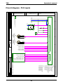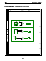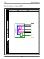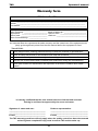
1
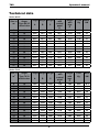
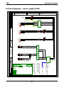
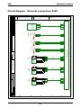
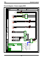
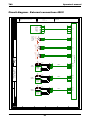
TKS Operator’s manual Operator’s manual TKS Kuhn FeedMixer From serialno.: 005 - TKS Kuhn FeedMixer EN, issue 2 2015-05 988872 1 TKS Operator’s manual CE - Declaration of conformity We, T. Kverneland & Sønner AS, Kvernelandsvegen 100 N-4355 Kverneland Norway declare that the product: TKS Kuhn - FeedMixer has been built in conformity with the Machine Directive 2006/42/EC and meets the relevant fundamental health and safety requirements. Kverneland, 08 Mai 2015 Tønnes Helge Kverneland General Manager Enter the serial number of the machine here : T. Kverneland & Sønner AS, manufacturer of agricultural products, reserves the right to change the design and/ or specifi cation of its products without prior warning. This does not imply any obligation to modify previously supplied machines. 2 TKS Operator’s manual Guarantee At the end of the book you will find the warranty form, and this have to be filled out and returned to TKS This TKS product is guaranteed against manufacturing and material defects for one year. If the owner wishes a defect to be covered by the product guarantee, he or his representative must inform the dealer of this when ordering parts and/ or repairs. Claims must be reported within the guarantee period. The dealer must complete a claims form for each case covered by a guarantee and send it to TKS or TKS’s distributor/ importer within the 10th of the month following the one in which the defect was reported. The defective parts shall be marked with the claim number and be kept for up to 6 months so that TKS or TKS’s distributor/ importer can inspect them. Since TKS products are used outside the manufacturer’s control, we can only guarantee the product quality, and not that it will perform its function, nor are we liable for any consequential damage. . The guarantee is not valid if: a) third party spare parts are used, or the product is repaired or altered without the approval of TKS b) the operating and servicing instructions have not been followed. c) the machine has been used for other purposes than those for which it is designed. The guarantee does not cover damage due to normal wear and tear. Offi cial safety regulations specify requirements that apply to the users/ owners and manufacturers of this machine, relating to the careful review of safety hazards that may arise when this type of machine is used correctly. Therefore, TKS and our importer/ distributor are not responsible for the functioning of components that are not shown in the spare parts catalogue for this product. TKS reserves the right to change the design of the product without this implying any obligations in relation to previously supplied machines . The guarantee does not cover damage due to normal wear and tear. Offi cial safety regulations specify requirements that apply to the users/ owners and manufacturers of this machine, relating to the careful review of safety hazards that may arise when this type of machine is used correctly. Therefore, TKS and our importer/ distributor are not responsible for the functioning of components that are not shown in the spare parts catalogue for this product. TKS reserves the right to change the design of the product without this implying any obligations in relation to previously supplied machines . NB! It must be possible to identify all enquiries relating to this product by the product’s serial number; see page 7 on Machine identification. 3 TKS Operator’s manual Content CE - Declaration of conformity . . . . . . . . 2 3.4 Mixing . . . . . . . . . . . . . . . . . . . . . . . . . 31 Guarantee . . . . . . . . . . . . . . . . . . . . . . . . 3 3.5 Warning sounds . . . . . . . . . . . . . . . . . 31 Introduction . . . . . . . . . . . . . . . . . . . . . . . 6 4 Using the screen and PLC . . . . . . . . . . 32 Machine identification . . . . . . . . . . . . . . . 7 4.1 Screen . . . . . . . . . . . . . . . . . . . . . . . . 32 Technical data . . . . . . . . . . . . . . . . . . . . . 8 4.2 Numeric keypad . . . . . . . . . . . . . . . . . 32 Technical description . . . . . . . . . . . . . . . 10 4.3 Selecting a value . . . . . . . . . . . . . . . . 33 Model description and area of use . . . . 13 4.4 On / off key . . . . . . . . . . . . . . . . . . . . 33 Safety . . . . . . . . . . . . . . . . . . . . . . . . . . 14 5 Operation . . . . . . . . . . . . . . . . . . . . . . . . 34 1 Function . . . . . . . . . . . . . . . . . . . . . . . . . 20 5.1 Activate FeedMixer . . . . . . . . . . . . . . . 34 1.1 Auger . . . . . . . . . . . . . . . . . . . . . . . . . 20 5.2 Menus . . . . . . . . . . . . . . . . . . . . . . . . . 34 1.2 Knives . . . . . . . . . . . . . . . . . . . . . . . . . 20 5.2.1 Home . . . . . . . . . . . . . . . . . . . . . . . 34 1.3 Overflow extension . . . . . . . . . . . . . . . 21 5.2.2 Perform a mixing operation . . . . . . 35 1.4 Counter knives . . . . . . . . . . . . . . . . . . 22 5.2.3 Perform a feedout operation . . . . . 35 1.5 Door location . . . . . . . . . . . . . . . . . . . 23 5.2.4 Settings . . . . . . . . . . . . . . . . . . . . . 36 1.6 Ladder . . . . . . . . . . . . . . . . . . . . . . . . 23 5.2.5 Manual control . . . . . . . . . . . . . . . . 36 1.7 Recycling - waste to resource - . . . . . . 24 5.2.6 Feedout timer . . . . . . . . . . . . . . . . 37 2 Positioning and installation . . . . . . . . 25 5.3 Settings . . . . . . . . . . . . . . . . . . . . . . . . 38 2.1 Installation . . . . . . . . . . . . . . . . . . . . . 26 5.3.1 Settings for mixing . . . . . . . . . . . . . 38 2.2 Check gear oil level . . . . . . . . . . . . . . 26 5.3.2 Settings for feedout . . . . . . . . . . . . 38 2.3 Function check . . . . . . . . . . . . . . . . . . 27 5.3.3 Settings for activation . . . . . . . . . . . 39 2.4 Remote control of the . . . . . . . . . . . . . . 5.3.4 Weight settings . . . . . . . . . . . . . . . . 41 feedout process . . . . . . . . . . . . . . . . . 28 5.3.5 Options . . . . . . . . . . . . . . . . . . . . . . 42 Using FeedMixer . . . . . . . . . . . . . . . . . 29 5.3.6 Energy log . . . . . . . . . . . . . . . . . . . 43 3.1 Loading . . . . . . . . . . . . . . . . . . . . . . . . 29 5.3.7 Clock . . . . . . . . . . . . . . . . . . . . . . . 44 3.2 Loading sequence . . . . . . . . . . . . . . . 30 5.3.8 Language . . . . . . . . . . . . . . . . . . . . 44 3.3 Feed quantities . . . . . . . . . . . . . . . . . . 31 5.4 Alarms . . . . . . . . . . . . . . . . . . . . . . . . 45 3 4 TKS Operator’s manual 6 Troubleshooting . . . . . . . . . . . . . . . . . . 46 7 Maintenance and care . . . . . . . . . . . . . . 48 7.1 General safety instructions . . . . . . . . . 48 7.2 Recommended bolt torque . . . . . . . . . 49 7.3 Cleaning . . . . . . . . . . . . . . . . . . . . . . . 49 7.4 FeedMixer - operation . . . . . . . . . . . . . 50 7.5 Shear bolt protection . . . . . . . . . . . . . 50 7.6 The auger knives . . . . . . . . . . . . . . . . . 51 7.7 Lubrication . . . . . . . . . . . . . . . . . . . . . 53 7.8 Oil change . . . . . . . . . . . . . . . . . . . . . 54 7.9 Filling with a pump . . . . . . . . . . . . . . . 55 7.10 Lubrication table . . . . . . . . . . . . . . . . 56 7.11 Oil change gear motor . . . . . . . . . . . . 56 7.12 Lubricating the power . . . . . . . . . . . . . . transmission shaft . . . . . . . . . . . . . . . 57 8 Loading cell amplifier . . . . . . . . . . . . . . 58 9 Circuit diagram . . . . . . . . . . . . . . . . . . . 60 Warranty form . . . . . . . . . . . . . . . . . . . . 69 Notes . . . . . . . . . . . . . . . . . . . . . . . . . . . 73 5 TKS Operator’s manual Introduction Congratulations on buying your new TKS product. You have chosen a functional, high quality product. A network of helpful dealers will be able to advise you on its use, as well as provide servicing and spare parts. All TKS products are designed, tested and built in close cooperation with farmers and machine workshops to ensure optimal effi ciency and reliability. Please read this instruction manual carefully and familiarise yourself with the machine‘s manner of operation before starting to use it. There are many conditions and variables that can affect the machine’s functionality and manner of operation. It is therefore vital that you consider all known conditions and adapt usage according to these. A good understanding of the machine‘s manner of operation and performance, together with a high degree of knowledge with regard to feeding and feed types/consistencies will ensure the best possible result. The machine is a highly advanced feed robot that operates without the need for supervision and must be used in accordance with the applicable instructions from the manufacturer and other regulations in force at any given time. By being thorough and making the necessary adaptations to local conditions, you will ensure the best possible results. Yours faithfully T. Kverneland & Sønner AS MEKANISKE T. Kverneland & Sønner AS, Kvernelandsvegen 100 N-4355 Kverneland Norway www.tks-as.no Mail : [email protected] Phone : + 47 51 77 05 00 Fax : + 47 51 48 72 28 6 TKS Operator’s manual Machine identification The machine’s serial number and the address of the manufacturer are written on the machine. See the illustration on this page. Please use the information on the name plate when making any enquiries about spare parts or servicing. This product is CE marked. This mark, along with the associated written EU confi rmation, means that the product fulfi ls current health and safety requirements, and complies with the following directives: Machine Directive 2006/42/EC ICM_02 7 TKS Operator’s manual Technical data Series 80 VC Size in m3 Auger Type 80 VC w/end door 9 11 13 15 18 22 25 27 30 28 33 39 45 27 Lenght Height Height 4 6 8 10 12 16 20 22 25 27 30 28 33 39 45 Height with legs E Load Kg Motor kW 4157 2466 3455 22 A B C 1S 3325 1691 2472 1S 3350 1973 2487 4177 2748 3550 30 1S 3504 2242 2472 4177 3013 3660 30 1S 3583 2373 2471 4187 3143 3720 37 2S 5707 1690 2481 6573 2368 6060 37 2S 5760 1973 2481 6573 2651 6190 37 2S 5913 2243 2481 6573 2921 6340 37 2S 5987 2373 2481 6630 3051 6450 45 2S 6168 2562 2487 6731 3240 6385 45 3S 7995 1975 2810 8395 2575 9000 45 3S 8110 2245 2740 8510 2845 9500 45 3S 8260 2375 2862 8660 2975 10000 55 3S 8335 2525 2876 8735 3125 10500 55 2S 5987 2373 2481 6630 3051 6440 45 Lenght with control panel D Height with legs E Load Kg Motor kW 3160 1960 1800 18,5 Series 70 VL Size in m3 Lenght with control panel D Auger Lenght Height Height Type 70 VL w/side door A B C 1S 2760 1360 2250 1S 2835 1660 2275 3235 2260 2200 18,5 1S 3165 1722 2324 3891 2456 2870 22 1S 3241 2060 2321 2952 2797 2970 30 1S 3381 2311 2327 4029 3042 3070 30 2S 5373 1710 2343 6280 2410 5560 37 2S 5445 2050 2343 6315 2746 5690 37 2S 5570 2300 2343 6385 2996 5830 37 2S 5913 2243 2481 6573 2921 6340 37 2S 2983 2378 2487 6630 3056 6450 45 2S 6201 2562 2487 6736 3240 6480 45 3S 7995 1820 2810 8395 2420 9000 45 3S 8110 2080 2840 8510 2680 9500 45 3S 8260 2380 2862 8660 2980 10000 55 3S 8335 2530 2876 8735 3130 10500 55 8 TKS Operator’s manual Measure - FeedMixer ICM_03 ICM_04 9 TKS Operator’s manual Technical description 1 = Mixing hopper 2 = Extension kit 3 = Auger 4 = Weighting cell 5 = Gear unit 6 = El. cabinet 7 = Gear motor 8 = Feedout chute 9 = Counter knives with activator 2 3 8 6 7 1 5 4 ICM_05 10 TKS Operator’s manual Feedout chute on FeedMixer A = Feedout chute width end door, issue VC B = Feedout chute width side door, issue VL A ICM_06 B ICM_07 11 TKS Operator’s manual Fully assembled equipment Equipment: A Loading cell B Counter knife with activator A B ICM_15 ICM_10 12 TKS Operator’s manual Model description and area of use FeedMixer is designed for cutting silage, round bales, square bales and most types of forage. It cuts most types of round bales and silage. The cut depends on the consistency and type of feed. FeedMixer is particularly useful for creating a good mix in a short time. It is therefore suitable for mixing full feed, which often involves mixing feed types of very different consistency and character. It is important that finer ingredients and smaller quantities are mixed quickly before the structure of the feed is damaged. With its powerful motor and augerdesign, you will quickly obtain a loose and homogeneous material that can be easily dispensed from all types of feed carts or belts. FeedMixer has vertical augers that produce a fine material in which the structure of the feed is retained. It is particularly important with pre-dried material that the feed is not compressed into wet lumps. This will reduce the feed intake to the animals. FeedMixer can be supplied in sizes from 4 to 45 m3. Sizes of 8–15 m3 are supplied with one auger, while sizes of 18–30 m3 are supplied with two augers. The electrical control system controls all functions, and it has been configured for operating a conveyor belt. The mixing motor is controlled by frequency inverter, enabling a soft start-up and stop. The controller also includes measurement of power consumption, so you can keep an eye on what it costs to use FeedMixer for a day, a week or a month, for instance. An electrical stationary mixer is significantly cheaper to run than tractor-powered models. NB: The instructions given in this operator’s manual apply to standard operating conditions. Individual circumstances may arise at the premises of the user that deviate from the instructions provided here. The need to make changes to the machines and equipment as a result of such circumstances shall not constitute grounds for making a claim against the manufacturer or supplier. To achieve the best possible result, more time and involvement is required than “traditional” feedout methods. The quantities of individual feed types and the duration of the mixing process must remain the same each time mixing is performed if composition and consistency are to remain uniform – otherwise feed intake and production will be affected. All functions are electrically operated. The counter knives are moved in position during mixing and retracted during the discharging process. Where FeedMixer has to discharging several times a day, the door is closed between each operation. FeedMixer can be equipped with a sensor that reset mixing time, when a new bale is loaded into the machine while mixing process initiated When weight system record loads under 200 kg in the mixer while discharging, the rotational speed increases in order to clean the augers and threw off the rest of the feed. Climate, temperature, grass types, time of cutting, cutting/pressing equipment and conservation methods are some factors that may affect the functionality and performance of the machine. It is important to adapt and adjust the machine to suit local conditions in order to achieve the best possible result. Chapter 1 describes the design of the machine and the functions of its individual components. FeedMixer is occasionally pictured with optional equipment fitted. Any optional equipment is labelled as such in this instruction manual and can be supplied at an additional cost. 13 TKS Operator’s manual Safety Please pay particular attention to this symbol. It designates a safety risk, and describes precautions that must be taken to avoid accidents. Before operating, adjusting or repairing the machine, the user, technician or owner should familiarise himself with the safety instructions contained in this installation manual. Safety at work is your responsibility! General assessment Please read and understand these general safety instructions. In order to be able to load the bale into the hopper, the machine must be open. This means that people may come into contact with moving parts if they are standing in the immediate vicinity of the machine while it is in use. Warning! Once the auger is running, never lean over the top edge of FeedMixer or enter the hopper when the machine is operating. If the machine is placed in a sunken floor, the distance from the floor to the top of FeedMixer must not be less than 1.5 m. It is a conditional requirement of using the machine that no one must be in the immediate vicinity of the machine during use. In addition, in terms of machine type, FeedMixer is of conventional agricultural design and, from a safety perspective, the solutions choosen are considered to be on a par with or superior to existing products on the market. General safety instructions Use of the machine The machine must only be used for the purpose for which it is designed. Operating The machine operator must remain at the end of the machine where the control box and the associated operating panel are mounted. Supervision The owner/operator must ensure that the area is sufficiently signposted and that there is no unauthorised access. 14 TKS Operator’s manual The machine’s method of operation The operator must familiarise himself with the machine’s method of operation and function so that the machine can be used in a safe and appropriate manner. Keep a safe distance Humans and animals must be kept away from the machine when it is in operation. Keep your distance from working, rotating and moving parts. Think safety at work Never climb on the machine while it is operating. When performing maintenance, the power supply must be disconnected Warning – audio and illuminated indicator The control system (software) has been updated for safe start-up. A built-in buzzer sounds for 30 seconds before start-up of the machine. This audio signal is accompanied by a light signal that flashes during the entire period of operation. Protective guards Check that all guards are in place and installed correctly. Do not start the machine until this has been done. Damaged guards must be repaired or replaced immediately. Spare parts For safety reasons we recommend that you only use original spare parts. The use of third-party spares invalidates the product guarantee. Maintenance Ensure that the machine is properly maintained and is kept in good condition. Never attempt to change the mechanical workings of the machine. The area in which the machine is operating Must be physically sealed off or locked to prevent danger to humans or animals. Control panel The power supply must be cut off before opening the panel. 15 TKS Operator’s manual Additional safety instructions The machine is marked with a warning signs. If these signs are damaged, they must be replaced. The order number is shown on the illustrations in this section. Side 17 for their location on the machine. Warning sign UH220532 (Fig. 1) Be careful! Ensure that you read and understand the instruction manual before using the machine, and before making any adjustments or performing any maintenance. Fig. 1 Warning sign UH220536 (Fig. 2) Risk of crushing hand. Keep away from the bedknives. Fig. 2 Warning sign 988346 (Fig. 3) The main power switch must be secured by a padlock. Work should only be performed by authorised personnel. Fig. 3 Warning sign UH220534 (Fig. 4) Disconnect all electrical connections before carrying out welding work or maintenance. Fig. 4 16 TKS Operator’s manual Overview of safety risks UH220532 UH220534 988346 988346 UH220536 17 TKS Operator’s manual Lifting the machine The lifting straps are attached to the points screwed into the bottom of FeedMixer. See Fig. 5 Use an extra strap to help keep the machine in position. Caution! Never stand underneath a suspended load. Any persons carrying out lifting operations must of course have the appropriate qualifications/ skills. Be careful! Keep your distance when moving the machine. Ensure that there are no persons underneath or near the machine during lifting. New machine - caution Read the operator’s manual Be particularly careful when starting a new machine for the first time. Installation faults, incorrect operation, etc. may lead to expensive repairs and loss of earnings. The TKS product guarantee does not cover damage resulting from failure to follow the recommendations contained in the instruction manual. Please pay particular attention to this symbol. It is used to highlight important information, to help prevent incorrect installation and operation. Pay particular attention to the following when commissioning a new machine: • Check that the machine is correctly installed and that it is not damaged. Check to make sure that electrical cables are long enough, and positioned in such a way that they can track the movements of the machine without being damaged.bevegelser uten å skades. 18 TKS Operator’s manual Lifting point UH220307 A ICM_22 ICM_09 Fig. 5 Lifting point Detach the four lifting points (A) after the machine is hoisted into place, and fit them to the outside of FeedMixer for subsequent use as and when needed. See Fig. 5 19 TKS Operator’s manual 1 Function 1.1 Auger There is a shear bolt connection between the layshaft and the planet gear. If the machine becomes overloaded the shear bolt will shear, thus stopping power transmission to the auger. During the mixing process, the auger transports the feed upwards to the middle of the mixing hopper. The feed then falls off the mixing auger and a mixing cycle is created. Fig. 6 1.2 Knives The auger (2), which is equipped with knives (1), finely chops up the feed constituents that have been loaded into the mixing hopper. A discharging arm (3) together with the blades of the auger ensure a more stable and even discharging process. See Fig. 7 4 5 2 The knives on the auger can be set to an aggressive position (4) or a normal position (5). The adjustable knives allow the mixing system to be adjusted to suit individual operating conditions at the company and the structure of the feed constituents. 1 3 Aggressive = short mixing time, higher power consumption. Normal = longer mixing time, lower power consumption. (E.g. if the fuses are smaller) 20 TKS Operator’s manual 1.3 Overflow extension A The anti overflow extension (A) prevents feed from being thrown over the edge of the hopper during the mixing process. The anti overflow extension prevents round bales from getting stuck while it being ground up. See Fig. 8 ICM_17 Fig. 8 21 TKS Operator’s manual 1.4 Counter knives A better cut is achieved by using counter knives (A). Counter knives are used to prevent rotating of round and square bales for a better cut. The counter knives move in and out automatically, depending on whether the FeedMixer is in mixing mode or discharging mode. • The counter knives are moved at mixing mode. • The counter knives are retracted in discharge mode. A Automatic movement of the counter knifes can be disabled. The counter knifes can be placed in the desired position – deployed, retracted, or in the midway position. See Fig. 9 ICM_17 Enabling the counter knives. See Figure 13a page 42 A ICM_16 Fig. 9 22 TKS Operator’s manual 1.5 Door location FeedMixer has as standard option 3 doors. Possible optional discharge door location can be provided on request. See Fig. 10 ICM_12 ICM_15 Fig. 10 1.6 Ladder Using a ladder (C) the operator can stand in a safe manner and keep an eye on the mixing process. If the ladder is used when discharging, an error may occur on the weight system. See Fig. 11 C ICM_17 Fig. 11 23 TKS 1.7 Operator’s manual Recycling - waste to resource - TKS’s products rely on electrical and electronic components in order to work. These fall under the generic term of EE products. TKS’s products use typical components such as cables, switches, motors, control units, etc. When TKS products are thrown away those components containing contaminants should be treated and sorted in such a way that they do not pollute the environment. Contaminants should be taken care of safely. Distributors are obliged to accept EE waste from products in the range of goods they sell. This waste should be kept safe and sent on to an approved waste recipient or treatment plant. EE waste must be sorted and transported in such a way that it is not damaged or destroyed. If you need further information on the treatment of EE waste, please contact your distributor. TKS is a member of Renas. (National program for the collection/treatment of electrical/electronic waste) Regards TKS AS 24 TKS Operator’s manual 2860 2 Positioning and installation ICM_25 Fig. 12 NB! Read before positioning FeedMixer: • The surface must be designed to withstand the load of FeedMixer. • It is important that the surface is smooth and flat leveled to ensure that the weight system can work properly. • If the machine is placed in a sunken floor, the distance from the floor to the top of FeedMixer must not be less than 1.5 m 25 TKS Operator’s manual 2.1 Installation • The machine is delivered assembled from TKS. • Follow the installation instructions for FeedMixer precisely in order to avoid subsequent breakdowns. • Remove all packaging. • Remove equipment stored inside the machine. • FeedMixer is secured using two expansion bolts placed diagonally opposite one another in each base plate (A). These are included with the machine. • The feeding shute for the door is flat-packed with associated bolts, and must be fitted in front of the door. ICM_17 A Important! • All wiring for FeedMixer is performed at the factory by TKS. • The power supply cable must be fitted by an authorised electrician. • To achieve optimal operation, the power supply must have uniform and correct voltage in all phases. Fuses and cables must be adequately dimensioned. Se Fig. 13 ICM_26 Fig. 13 2.2 Check gear oil level • After installation and before FeedMixer has been commissioned, all the lubrication points on the driveshafts must be lubricated. • Check the gear oil level in the oil tank. The level must not be below the mark (A) on the oil tank. A See Chap. 7 on Maintenance and inspection ICM_18 Fig. 14 26 TKS Operator’s manual 2.3 Function check Important! • Be careful when starting FeedMixer for the first time. • Check all the functions on FeedMixer • The functions are tested from the display • Open manual control in the menu • Press and hold the keys for the various functions See Fig. 15 Fig. 15 See Chap. 5 on Operation 27 TKS Operator’s manual 2.4 Remote control of the feedout process When using FeedMixer together with an automatic feeding machine, separate pieces of electrical equipment must be connected. This equipment can either be a photocell a limit switch, or a radio transmitter and receiver. Connection must always be carried out by an authorised electrician. Photocell The photocell is mounted on an I-beam. See Fig. 16 A Function: The limit switch measures the fill level in the feed cart or wagon. Fig. 16 Limit switch The limit switch is fitted to the rail Activated by the feed cart or wagon B See Fig. 17 Function: The limit switch gives a signal when the feed cart or wagon is in position ready for filling. Fig. 17 28 TKS Operator’s manual 3 Using FeedMixer Dangerous situations may occur if components fail as a result of overloading FeedMixer! The maximum payload of FeedMixer and the loading sequence for individual feed constituents must be observed There is a risk of crushing and entrapment with subsequent risk of injury if you come into contact with any of the machine’s moving parts. Warning! • Once the auger is running, never lean over the top edge of FeedMixer or enter the hopper. Overloads may occur and blockages may be created if feed constituents get stuck on the counter knives. Overloads reduce the performance and life time of FeedMixer. The TKS warranty does not cover damage caused by overloading. 3.1 Loading FeedMixer may only be loaded using suitable tools such as: • Tractor with front loader/wheel loader • Conveyor belt • TKS Magazine R2 • TKS FeedHopper/FeedHopper Junior • Crane Important! • When loading FeedMixer, carefully drop the feed from the lowest possible height inside the hopper. • Dropping heavy loads from high heights may damage the equipment and is not covered by the warranty. • Make sure that the feed does not stick to the edges of the hopper during loading. • The hopper should ideally be loaded in front of or behind the auger, i.e. not in the middle just above the auger. • With ideal loading it speeds up the mixing process, and it use less power. 29 TKS Operator’s manual 3.2 Loading sequence Light, dry feed is loaded first, before loading heavier, wetter feed. Loading the bales • Load the driest, lightest bale first. • Wait for the bale to be ground up and cut into an even mixture before loading the next bale. • Heavier, wetter bales (and any frozen bales) are loaded at the end. We recommend consulting a feed consultant to achieve the best possible mixture and optimal use of raw materials. • Highly structured feed constituents (hay, straw etc.) should be loaded with the auger rotating. • The mixing process can be left to run for a few minutes before adding the next constituent. • Concentrated feed, and minerals should be loaded with the auger stationary. A stationary augerincreases the accuracy of the scales. • Forage, maize and heavier feed constituents are added later during the mixing process with the augers rotating. • Feed constituents with a higher water content, e.g. scraps, potato peel or turnip, are added toward the end of mixing process. • Liquid feed constituents such as molasses and water are added at the very end. 30 TKS 3.3 Feed quantities 3.4 Mixing Operator’s manual The loading quantity for a FeedMixer may vary due to the different feed constituents being loaded. The loading quantity depends on the following factors: • The volume of the mixing hopper • The dry matter content of all the feed con stituents • Structure and straw length • Order of loading The type and structure of the feed constituents being used, along with the desired cutting length of the feed mixture, determine the duration of the final mixing process. • The mixing process will use longer time when using structured feed constituents. • The counter knives slow the circulation of the feed in the mixing hopper. The further the counter knives are inserted into the mixing hopper, the braking effect gives better charging and mixing effect. • The counter knives should be used to ensure good cutting of round and square bales. • Blunt knives increases power consumtion power, for which reason the knives should be sharpened regularly. See Chap. 7 on maintenance. 3.5 Warning sounds • FeedMixer gives audio alerts for functions during loading. • If too much feed is loaded into the hopper, FeedMixer will give an audio signal indicating that the motor is operating at maximum load. No more feed must be loaded. • The audio signal persists for as long as the motor remains under such strain. • Two short “beeps” – 5 seconds pause between sounds. • If more than 200 kg of feed are loaded after the mixing process is started, a new mixing time is activated. This requires that automatic reset of the mixing time has been enabled. See Chap. 5.3.1 • Two long “sounds” 31 TKS Operator’s manual 4 Using the screen and PLC 4.1 Screen The control system has a touchscreen, meaning that you can control it by touching the screen directly. Touch the screen with your fingers or use a soft-touch stylus located in the control cabinet. Do not press too hard, as this can damage the screen. If the screen has not been active for a few minutes, it will enter screen saver mode. The screen will be off in this mode. Touch any part of the screen in order to reactivate it. The menu keys are displayed on the left-hand side of the screen. Close windows by pressing the X in the upper right-hand corner to go to the Home screen. NB! Clean the screen using a moist cloth. 4.2 Numeric keypad Values in fields with blue borders can be changed. Touch the number and a numeric keypad will display on the screen. The top of the screen shows the Max/Min value that can be entered in this field. Enter a new value using the number keys. If an incorrect value was entered, press the <─ key and delete the most recently entered number. Press CLR to delete everything. To enter a negative value, press - before entering the value. Once you have selected a value, press the ENTER button. This will save the value and close the keypad window. To cancel, press X in the upper right-hand corner. The old value will continue to be active. To enter times in the feedout schedule window, begin by entering the hours – then press period. Then enter the minutes. Make sure that the time is right. For example, if you enter 12:65, this will be ignored – enter 13:05 instead. See Fig. 7 Fig. 19 32 TKS Operator’s manual 4.3 Selecting a value Selecting pre-programmed values from a list. • Open the list – Press the value or the down arrow • Select a value from the list See Fig. 9 Fig. 20 4.4 On / off key Enable or disable a function using the on/off key. • Unchecked means off, disabled • A checkmark means on, enabled See Fig. 10 Fig. 21 33 TKS Operator’s manual 5 Operation 5.1 Activate FeedMixer When FeedMixer is switched on, or when the emergency stop button is pressed, screen picture will display. Read the instructions on the screen and make sure that the machine can be used properly. Release the emergency stop button if it has been tripped. Press “ACTIVATE FEEDMIXER” and hold it down for three seconds before Home screen appears. Picture 1 5.2 Menus 5.2.1 Home When FeedMixer is activated, the Home screen displays. The following displays: • Menu on the left • Start keys for mixing and feeding on the right • The load of the content in the mixer is shown at the bottom • The current menu selection is indicated by a key highlighted in dark grey • The red line at the top shows FeedMixer activity and the clock time Picture 2 34 TKS Operator’s manual 5.2.2 Perform a mixing operation • Load FeedMixer with feed. • Load shows the number of kg loaded material. • Adjust desired Mixing time in the field at the START MIXING key • Enter the number of minutes and then press Enter • Press and hold the START MIXING key for three seconds • The motor goes through its start-up sequence and mixing begins. Once mixing has commenced, the START MIXING key changes to a red STOP key. Below the keys is a field with a Mixing time left It can be changed if desired. The START FEEDOUT key is locked, but the number of kilograms to be dispensed can be changed. Once mixing is complete, FeedMixer stops on its own and the screen displays two green start keys. Picture 3 5.2.3 Perform a feedout operation After mixing, a feedout operation can be started In the field on the START FEEDOUT key, enter the Feedout quantity in kg. Press and hold the START FEEDOUT key for three seconds, FeedMixer begins the feedout sequence. The door opens, the counter knives retreats, the conveyor starts and the feed discharges. Picture 4 Once the feedout operation has commenced, the START FEEDOUT key changes to a red STOP key. Two fields display below the keys. The first field shows the quantity discharged so far in kg, and the second shows the quantity for this feedout session in kg. The START MIXING key is locked, but the Mixing time can be changed. Once the feedout operation is complete, FeedMixer stops on its own and the screen displays two green start keys. To empty FeedMixer completely, enter 0 kg in Feedout quantity before commencing the feedout operation. 35 TKS Operator’s manual 5.2.4 Settings Open the settings using Settings in the menu. Eight sub-menus display for FeedMixer settings: • Mixing – settings for mixing • Feedout – settings for feeding • Activation – settings for remote control • Load – settings for the weighing system. • Options – settings for the motor and equipment • Energy log – energy consumption and hour meter • Clock – setting the time and date • Language – select display language Picture 5 The program version of the PLC is displayed at the bottom: PLC 1.50 and screen: HMI v1.50 5.2.5 Manual control Open manual control by touching Manual in the menu. Operation of the door • Open the door using the up arrow • Close the door using the down arrow • The door is operated when the arrow key is pressed, and stops when the arrow key is released • The arrow key lights up green on activation • The door stops once the end position is reached • The door also moves on the screen Picture 6 Operation of counter knives (Plate 1 or 2) • Counter Knife 1 is moved in position using the right arrow key. (Plate 1) • Counter Knife 1 is retracted using the left arrow key. (Plate 1) • Counter Knife 2 is moved in position using the left arrow key. (Plate 2) • Counter Knife 2 is retracted using the right arrow key. (Plate 2) • The arrow key lights up green on activation • The counter knives stops once the end position is reached 36 TKS Operator’s manual Operation of motor • In manual operation, the motor rotates in the forward direction. • Start motor at pre-defined speeds • Lo = low speed • M = medium speed • Hi= high speed • The motor runs for as long as the key is held down, and stops when it is released. • The key lights up green on activation. Operation of conveyors • • • • Two conveyors can be operated individually. 1 – operates conveyor 1 2 – operates conveyor 2 The conveyors run for as long as the key is held down, and stop when it is released. 5.2.6 Feedout timer Open the schedule using Feedout timer in the menu. FeedMixer can be set to discharge automatically according to a schedule. Up to 16 different times can be configured individually. It’s appropriate to use this function if a feeding machine does not have a separate feedout schedule program. • • • • • Picture 7 Configure the desired feedout time. See Chap. 4.2 for how to enter the time Enter the feed quantity in kg for each time Enable this feedout session using En D – shows the feedout door When at least one feedout session is enabled, the feeout timer key on the Home screen will be green. When automatic feedout is used, the feed must still be mixed manually. Mixing must be performed at a time between two automatic feedout sessions. If FeedMixer is empty when feeding, FeedMixer will stop and give a screen alert. 37 TKS Operator’s manual 5.3 Settings 5.3.1 Settings for mixing Choose mixing speed by setting a predefined motor speed. • Low – Low • Med – Medium • High – High • Auto – Automatically adjusts the engine speed between low and high. FeedMixer always adjusts to the lowest load. When new material is loaded into FeedMixer, the load will increase. You can choose to start the mixing process from the beginning. Specified mixing time starts decounting from set point. • Enable/disable – Automatically reset mixing time after FeedMixer is loaded. Picture 8 5.3.2 Settings for feedout Choose a feedout speed by setting a predefined engine speed. • • • • Low – Low Med – Medium High – High Auto – Automatically adjusts the engine speed between low and high. FeedMixer always adjusts to the lowest load. When FeedMixer is used together with FeedRobot or FeedBelt, the feedout speed must be set to Medium or Low. This is important in order to achieve an even feeding process. Picture 9 If feed is disharged at a small quantity and FeedMixer is not fully emptied each time, the door can be left open until the next feedout session. When FeedMixer is completely empty, the door closes automatically in order to be ready for the next loading. • Close door after feedout – Enable/disable. 38 TKS Operator’s manual High-speed cleaning • This function causes the motor to operate at a high speed to eject any feed left on the auger. After the set time, the motor speed is reduced, and FeedMixer feed out the remaining feed • Enable/disable. • Enter remaining load in the FeedMixer when cleaning has to start. • Enter the duration of cleaning: 1–10 seonds. Conveyor It is possible to connect up to two conveyors to FeedMixer. The conveyors start each time discharging, and stop after the specified length of time when the auger has stopped. • Enable conveyor. • Specify stop delay (time for emptying the conveyors) 5.3.3 Settings for activation Activation by hold signal FeedMixer can start the feedout process in response to external signals given by feeding machines. The start signal must be an active signal the entire time the feedout is in progress. This refers to a hold signal. When the signal is interrupted, the feedout process stops. Feedout and the conveyors can be controlled independently of one another. • Feedout – enable/disable (circuit diagram -X3:1) • Conveyor 1 enable/disable (circuit diagram -X3:3) • Conveyor 2 enable/disable (circuit diagram -X3:3) Conveyors 1 and 2 start at the same time, but may have different stop times configured. Adjust stop delay. Picture 10 39 TKS Operator’s manual Activation by pulse signal FeedMixer can start the feedout process in response to machines with a pulse signal. This means that FeedMixer starts with one signal and stops with another. In order to prevent FeedMixer from starting in response to the wrong signal, the signals must have a minimum duration. • Enable/disable pulse signal • Shortest start signal – adjust signal length (circuit diagram -X3:5) • Shortest stop signal – adjust signal length (circuit diagram -X3:6) Activation by FeedRobot Picture 11 When FeedMixer is used together with an external feed cart or wagon, such as a FeedRobot, FeedMixer can be started using a photocell and switch. • • Enable/disable the function Photocell act/deact. delay Photocell activating/diactivating delay – how long the photocell must have a stable signal before FeedMixer reacts. • Photocell react. delay Delay until reactivating of photocell – period of time after the end of the feedout process until the next feed may begin. • Switch act. delay Switch activation delay – how long Feed Robot must be in the switch position before the feedout process begins. Switch deact. delay Switch deactivating delay – time to elapse before FeedMixer stops the feeding process if FeedRobot leaves the position. See picture 10 40 TKS Operator’s manual 5.3.4 Weight settings Settings for weighing system and weight functions are configured here. Load cells • • Picture 12 • • Load cells enabled – enable/disable load cells. Without the loading cells it is not possible to display the load, and the functions related to load will not work. It may be appropriate to disable the loading cells during a period when the loading cells are out of order. Total load – shows the same value as the loading cell amplifier. (Box with red numbers) Calculated load – shows the load of the feed in the FeedMixer. Reset weight – sets the calculated load to 0. FeedMixer must be completely empty. Hold the key for three seconds to reset. Blockage detection This function is used to prevent blockages in the door outlet. If there is no reduction in load of the feed during the feedout process, FeedMixer will stop after the set time and give an alarm. This function is useful during automatic feedout when a connected machine may lead to blockages if it stops. • Enabled – Enable/disable this function. • Stop delay – configure the desired time to stop. Should not be shorter then 60 seconds. 41 TKS Operator’s manual 5.3.5 Options Other settings and enabling/disabling of various functions can be performed here. • Door enabled/disabled • Picture 13a • • • • – Enable the door to allow FeedMixer to automatically open/close the door when feeding. If disabled, the door must be controlled manually. Door 1 opening time – Configure the desired opening height for the door during automatic feedout. Enter opening time in seconds it takes to open the door to the level desired. Enter value 0 and door opens completely. Plate 1 or 2 enabled (Counter knife 1 or 2) – Enable counter knives to allow FeedMixer to automatically move counter knives in position when mixing and retract them during the feedout process. When counter knives are disabled, they are stationary, and can be moved manually to the desired position. Motor reverse enabled/disabled – When mixing and feedout, the auger will rotate in reverse approximately a quarter revolution in order to loosen the feed before rotating in the working direction. This avoids overloading the motor on start-up. This function must be used when FeedMixer is loaded to the limit. Freezing protection enabled/disabled – During cold times of year, the feed may freeze to the auger and sides, and make it difficult for the auger to turn. You can prevent feed from freezing to surfaces by setting the auger to turn at defined intervals. Configure the desired interval. Maximum feedout time – To avoid overload, the maximum feedouttime is limited to 60 minutes. This time can be adjusted as desired. Move to the next screen using the arrows on the right. 42 TKS Operator’s manual External alarm input Off / NO / NC Picture 13b – Used when a connected machine may give an error message. This signal causes FeedMixer to stop. (Connected to -X3:4). NO – normally open signal NC – normally closed signal • Motor load target for auto speed – the motor’s specified load is entered here as a percentage. This figure is converted to real amperage (A). This parameter is used to calculate auto speed during mixing or feedout. • Motor overload alarm – enable / disable – Give an audio alarm when the motor has too heavy load. Do not load any feed until the alarm stops sounding. • Auger run time after emptied FeedMixer – When FeedMixer is completely empty after a feedout, the auger will continue to run for a time. Enter the desired time. 5.3.6 Energy log Information about energy consumption and the hour meter can be read here. Energy consumption • FeedMixer calculates the energy consumption of the last mix, over the last 24 hours, the last seven days, and total consumption. Enter the price of energy in EUR/kW. FeedMixer calculates the cost of consumption. Picture 14 Hour meter • Motor operating time • Number of times door is opened • Number of counter knife (Plate) movements in/out 43 TKS Operator’s manual 5.3.7 Clock Time • Hours hh, minutes mm, seconds ss, adjusted individually. Date • Day DD, month MM, year YY, adjusted individually. • Day of the week chosen from the list • Press Apply to save Picture 15 5.3.8 Language Select display language Picture 16 44 TKS Operator’s manual 5.4 Alarms FeedMixer stops when an alarm is triggered. The screen shows the alarm window and which alarm was triggered. The window can be closed by pressing the X in the upper right-hand corner. A yellow symbol displays on the Home screen. Touch the symbol to open the alarm window again. Reset the alarms using the Reset alarm key If the error has not been corrected, the alarm will trigger again shortly • The following error messages may display: • Frequency inverter fault • Conveyor fault • Door fault • Limit switch fault, counter knife 1 (Plate 1) • Limit switch fault, counter knife 2 (Plate 2) • Feedout process fault • External alarm input See Chap. 6 Troubleshooting Picture 17 Picture 18 45 TKS Operator’s manual 6 Troubleshooting Fault Causes Procedure – error correction Auger does not rotate • The shear bolt in the boltconnection in front of the planet gear has sheared. • Replace the shear bolt. • Voltage too high. • Power cut. • Check the fuses. • Turn off the mains supply for 30 seconds. Motor, door and counter knives will be reset automatically. • The settings on the load cell amplifier are incorrect. • The load cell amplifier must be configured correctly. See Chap. 7 • Augerconnections on the scales’ components have come loose. • Retighten the augerconnections. • The switch is moist. • Insufficient contact in cables. • Clean and dry the switch • (do not use contact spray). Weight system, door or conveyor belt not working Scales are showing incorrect values Scales are not working Alarm! Door fault • El. actuator does not reach • Clean the outlet. top or bottom endpoints• Check clearance in the slot of the within 30 seconds. door. Alarm! Fault on limit switch for the counter knifes • Both of the limit switches in the el. actuator give a signal. Alarm! Frequency inverter fault • Power supply to the motor. • Check the power supply. • Overload/overheating on • Wait until the engine has cooled. motor. • Press Reset alarms to reset the frequency inverter Alarm! Conveyor fault • Power supply to the motor. • Check the conveyor. • Overload on motor. • Enable motor protection. Alarm! Feed feeding fault • When there is no reduction in weight during the discharging process. See Chap. 5.3.4 Alarm! External alarm input • Fault in connected machine. See Chap. 5.3. 46 • Check the cables for faults. • Check the door outlet. • Check connected machine. TKS Operator’s manual 47 TKS Operator’s manual 7 Maintenance and care 7.1 General safety instructions NB: • Every time the machine is used, it is important to check the condition of the machine, and to ensure that safety equipment is in place if required. • Make sure that all warning labels are in place and are legible. • Cleaning, lubrication and adjustments of FeedMixer or the driveshaft must only be performed with the motor and power supply turned off. • Recommended procedure: • Unaugerthe main switch on the machine. Only authorised personnel may carry out such work. • Avoid direct skin contact with oil and grease. In the event of personal injury caused by an oil leak, seek medical help immediately! • Once maintenance and servicing has been completed, take care to refit all guards correctly. • Check the torque of nuts and bolts initially after five hours of operation and then regularly (approx. every 50 hours of operation). Retighten if necessary. 48 TKS Operator’s manual 7.2 Recommended bolt torque A 8.8 10.9 Torque (Nm) A ICM_23 7.3 Cleaning M6 10.3 14.71 M8 25.5 35.3 M10 50.01 70.61 M12 87.28 122.58 M14 135.27 194.17 M16 210.84 299.1 M18 289.3 411.88 M20 411.88 576.5 M22 558.98 748.45 M24 710.99 1000.28 Clean the machine regularly – and thoroughly when necessary. Dirt attracts moisture and causes rust to form. After cleaning with a high pressure washer or steam, lubricate all rotating parts thoroughly. Warning: Electrical components such as the loading computer, junction box, loading cells and control panel must not be exposed to high pressure from a high pressure washer or steam cleaner. 49 TKS Operator’s manual 7.4 FeedMixer – operation • If FeedMixer is to be left inoperative over a longer period (more than one day), it must be emptied out completely. • Disconnect the machine from the power supply. • Clean the inside, outside and bottom of the machine. • Remove accumulated plant debris. • Repair paint damage in order to prevent rust. We recommend cleaning the machine as described in the section on maintenance. NB: Always disconnect the power supply before inspecting, servicing or repairing the machine. . The chapter on cleaning, servicing and maintenance is there for your own safety. 7.5 Shear bolt protection The gearbox is protected by a shear bolt connection. If the shear bolt shears, the following action should be taken: • Turn off the motor (turn the main switch to the “OFF” position and secure it). • Remove the source of the overload, e.g. a foreign object, from FeedMixer. • Remove the protective cover. • Remove the remains of the shear bolt. • Rotate the driveshaft to the connection shaft so that the holes align. • Replace the shear bolt with a bolt of the same type. Replace the shear bolt with a break bolt: Break bolt 10.9 – used on a 45 kW motor or Break bolt 8.8 – used on a 18–37 kW motor See Fig. 20 Fig. 20 50 TKS Operator’s manual 7.6 The auger knives Important! Turn off the main switch and secure it before entering the feed mixer. • The auger knives should be sharpened regularly. • Blunt knives increase power consumption and mixing times while reducing cutting performance. • The knives should be checked daily for visual faults. • Replace damaged and blunt knives immediately. To sharpen the knives, use an angle grinder with an undulating grinding disc. Se Fig. 22 The knives must only be sharpened on the smooth side, never on the undulating side. Carefully resharpen the knives so that the blades are not exposed to excessive heat. Fig. 21 Precautions when sharpening knives: • Warning! • There may be a risk of the knives expelling grinding particles! This can cause serious injury, particularly to the eyes. • When sharpening the knives, enter the empty feed mixer by stepping over the edge of the hopper. Fig. 22 • Use protective goggles and gloves. • Carefully sharpen the knives on the smooth side. • Clean the dust when sharpening is performed. 51 TKS Operator’s manual Remove all foreign objects (tools, etc.) from FeedMixer. If the blades become discoloured during sharpening: • 1 3 Excessive temperatures reduce the lifespan of the knives. • The blades can be switched from “aggressive” mode (1) to “normal” mode (2) by reposition knife (3) 2 Aggressive = short mixing time, uses more power. Normal = longer mixing time, uses less power. WARNING! • Exercise caution when fitting sharp knives! • They can cause serious cuts to fingers and hands. • Always use protective gloves when working with knives Fig. 23 • Use the following tools when replacing knives: • Two spanners (size 19), • protective gloves, edge guards for shielding the blades when fitting the knives. 52 TKS Operator’s manual 7.7 Lubrication Lubricating intervals for the main driveshaft are shown in the diagram on the left. Further information can be found in the user manual published by the driveshaft manufacturer. See Fig. 24 Oil level • Always check the oil level when oil is cold. • During operation the oil grows hot and the level rises. • See oil level at expansion tank. Level shall be at mark. See Fig. 24 Fig. 24 53 Fullfórvogn EUROMIX I 1870-2370-2570-2770 TKS Operator’s manual 7.8 Oil change NB: komme til Make sure that you do not slip on lubrication oil when draining and refilling the gearbox. Remove all traces of oil from the ground using a suitable product. 3 en. The drain plug for the right-angle gearbox is accessible underneath the machine. • Place a hopper under the gearbox. • Unscrew all fittings (1) and (2) under the right-angle gearbox. • Wait until the oil has drained out. • Disconnect the hose from the expansion tank (3). • Blow air with a maximum pressure of 0.5 bar (7.3 psi) into the gearbox in order to empty it entirely. • Fit all fittings (1) and (2) under the rightangle gearbox. See Fig. 25 .3 psi) inn i en. sen, kjør e litt. 1 2 Fig. 25 Before changing the oil in the right-angle gearbox, run the machine briefly to heat the oil slightly. It is sound practice – and is also required by law in some countries – to treat wastewater using sedimentation and oil separation, and to practise controlled handover. 54 TKS Operator’s manual Fullfórvogn EUROMIX I 1870-2370-2570-2770 7.9 Filling with a pump • Disconnect the two hoses (1) (2) that connect the gearbox to the expansion tank (3). • When the right-angle gearbox is empty, empty the hose (1) with a maximum pressure of 1 bar (14.5 psi). bler girboksen du slangen (1) 3 ndig for å ut av slangen e inn i slangen irboksen (5) til 1). NB: 1 This operation is necessary in order to check that the oil flowing out of the hose (1) during filling really is new oil. 5 4 2 bar (7.3 psi) akningene i Use an oil pump (4) to pump oil into the hose (2) connected to the bottom of the right-angle gearbox (5) until the oil flows out of the second hose (1). See Fig. 26 v den andre er for å være i kretsen. nn i bunnen av Fig. 26 en skal inn på Pump pressure The pump pressure must be less than 0.5 bar (7.3 psi) in order to avoid damaging the seals in the right-angle gearbox. , fyll de 2 When the oil begins flowing out of the other hose (1), wait a few seconds to be sure that there is no air left in the oil circuit. boks. ELL OMALA ss olje i Fit the hoses: The hose under the right-angle gearbox plugs into the bottom of the expansion tank. The hose at the top of the right-angle gearbox is fitted to the top of the tank. For machines with two augers, fill the two units separately at the top of the tank. Fill the tank up to the level marker. Vedlikehold og lagring Capacity 21 l (5.5 gal) of oil per gearbox. Capacity 49 l (12.9 gal) oil SHELL OMALA 150 for two gearboxes plus the oil in the expansion tank. 65 55 TKS Operator’s manual 7.10 Lubrication table Description Recommended lubricant Corresponding standard Right-angle gearbox 1 auger 21L + 2,5L =23,5L 2 augers 49L SHELL OMALA 150 ISO CKC 150/ SAE 80 W 90 Grease SHELL RETINAX EP2 NLG1 7.11 Oil change gear motor Fig. 27 Gearmotor Amount 4,0 liter AGIP KLUBER SHELL MOBIL Telium VSF 320 Syntheso D220 EP Tivela Oil WB Glygoil 30 SHC 630 56 TKS Operator’s manual Fullfórvogn I 1870-2370-2570-2770 7.12EUROMIX Lubricating the power transmission shaft 2 1 l • Remove the protective cone (1). • Pull the protective cone (2) backwards. • Lubricate the shaft and break pin, cross 250h • Refit the protection 100 h (3). • Turn the protective cone until it snaps into place (4). • Press firmly to connect (5). • Make sure the protective pipe is properly fitted (6). See Fig. 28 4 3 Read and follow the instructions in the user manual included with the power transmission shaft. tert (6). onene i ger med 6 5 Fig. 28 Vedlikehold og lagring 61 57 TKS Operator’s manual 8 Loading cell amplifier OPERATION OF THE LOADING CELL AMPLIFIER Remove the cover. Three switches on the right of the LED display labelled UP arrow, DOWN arrow and ENTER are used for programming. UP and DOWN: Change parameter ENTER accepts the data/exits the function. Press ENTER briefly and select a function using UP and DOWN. ENTER opens the function you are currently on. UP or DOWN changes the parameter. ENTER confirms the parameter. PROGRAM LOADING CELL AMPLIFIER: 1) Enable parameter 23 and enter the number of loading cells: 3 or 4 2) Enable parameter 24 and set the value to 0.825 3) Enable parameter 32 and set the value to 0 4) Enable parameter 34 and set the value to “U” 5) Enable parameter 20 and set the value to the appropriate load in kg. (0 if empty) Default setup (factory settings) is enabled using function 70. Function 70 is protected by a code: the code is 71. 1. Select function 70 using the UP/DN keys and finish using the ENT key. 2. Select function 71 using the UP/DN keys and finish using the ENT key. Once the function has completed, four horizontal lines appear briefly on the display. PTM junction box Plug/pin assignment: A: Yellow -> Signal B: White -> Supply + C: Red -> Signal + D: Green -> supply E: Guarding Moba junction box Plug/pin assignment: A: Green -> Signal B: Yellow -> Supply + C: White -> Signal + D: Brown -> Supply E: Guarding 58 TKS Operator’s manual 59 Operator’s manual TKS 9 Circuit diagram – Power supply 230V G:\Elektro\agri\FeedMixer\Drawings\ 1 1 I> I> 5 3 1 I> 6 4 2 230V input date -U1 PE PE name R/L1 U/T1 date 2 T/L3 PE -F2 I> 3 2 4 6 I> 1 3 5 I> -Q1 -F3 4 I> 2 4 6 I> 1 3 5 I> -Q2 4 Repl. by -F4 Transporter 2 motor 3 ~ 5 S/L2 W/T3 U/T1 7 8 9 PE Repl. f. M 4 5 6 PE 3 ~ 5 Transporter 1 motor 3 -M6 4 6 2.2kW 230V 2 2.2kW 230V 1 3 M V/T2 18.5-45kW 230V 2 -M5 1 2 3 PE Power -X1 3 ~ M 4 6 Mixer Motor -M1 2 Proved User Origin 1 Standard 3 A -F1 change 3.15 A -U2 -M2 1 2 5 11 3 4 -U3 1 11 6 -G1 2 21 + - 13 6 N L + Brake 2 M 14 4 - 3 + -M4 TR-EM-208 M 12 14 12 24 22 -K1' -M3 Brake 1 FeedMixer 230V Power supply TR-EM-208 - + 10 M Hatch 5 PE 15 PE + - 7 -X4 + Jumper 2 x ZDU2.5/3 8 + 10A -X3 24VDC Jumper 3 x ZDU2.5/4 Jumper 3 x ZDU2.5/4 -X2 + -X3 - -X2 - U2 DIP:1=ON, 2+3+4=OFF ADJ:1 = 90%, 2,3=MIN Control logic = PNP Adj: 1 2 3 DIP 8 Sheet 9 Sh. 1 U3 DIP: 1+2=ON,3+4=OFF, ADJ:1 = 50%, 2,3=MIN Control logic = PNP 7 A B C D E F 60 B C D E F control_cabinet230V Status PNP Electric 11.03.2015 11.03.2015 11:00 We reserve all rights in this document and in the information contained therein. Reproduction, use or disclosure to third parties without express authority is strictly forbidden. © TKS TKS Operator’s manual Circuit diagram – External connections 230V A B C D E F Status We reserve all rights in this document and in the information contained therein. Reproduction, use or disclosure to third parties without express authority is strictly forbidden. © TKS control_cabinet230V G:\Elektro\agri\FeedMixer\Drawings\ Electric 11.03.2015 11.03.2015 11:00 change 1 1 L1 L1 L2 L2 L3 L3 name F1 Power supply 230V+N date PE PE date Proved User Standard 2 2 M X1 3 ~ 1 2 3 PE -M1 18.5-45kW Mixer Motor 230V Delta connection Origin -M5 3 X1 4 5 6 PE M 3 ~ 2.2kW -M6 3 4 5 + - X2 1 2 3 X1 + - 5 -M3 4 5 4 5 1 2 6 3 + 3 4 5 Red Green Yellow X2 Brake 1 actuator signals 7x1.5 X1 + - Brake 1 actuator 1 2 Blue Brown 12 13 M 6 FeedMixer 230V External connections 10 11 M 3 4 5 Red Black Yellow 4 -M2 5 Hatch actuator signals 1 2 7x1.5 Control cabinet X1 7 8 9 PE M 3 ~ Repl. by 2.2kW 4 Transporter 2 motor 230V Repl. f. Transporter 1 motor 230V 3 Hatch actuator 1 2 Brown Blue -M4 + 4 5 6 7 7 3 X2 3 4 5 Red Green Yellow X1 + - Brake 1 actuator signals 7x1.5 14 15 M 7 Brake 2 actuator 1 2 Blue Brown 8 8 Sheet 9 Sh. 6 A B C D E F 61 Operator’s manual TKS Circuit diagram – Power supply 400V G:\Elektro\agri\FeedMixer\Drawings\ 1 I> I> 5 3 1 I> 6 4 2 date PE name -U1 PE 400V + N input 1 R/L1 U/T1 date 2 T/L3 PE -F2 I> 3 2 4 6 I> 1 3 5 I> -Q1 -F3 4 I> 2 4 6 I> 1 3 5 I> -Q2 4 Repl. by Transporter 2 motor 3 ~ 5 S/L2 W/T3 U/T1 7 8 9 PE Repl. f. 2.2kW 400V 4 5 6 PE 3 ~ 5 Transporter 1 motor 3 M 4 6 -M6 2 2.2kW 400V 1 3 M V/T2 18.5-45kW 400V 2 -M5 1 2 3 PE Power -X1 3 ~ M 4 6 Mixer Motor -M1 2 Proved User Origin 1 Standard 3 A -F1 change -U2 -M2 1 2 5 11 3 4 -U3 1 11 6 -F4 -G1 2 21 + - 13 6 I> I> 1 3 5 I> PE 2 4 6 L1 L2 L3 + 4 - + 14 M Brake 2 15 - 3 + -M4 TR-EM-208 M 12 14 12 24 22 -K1' -M3 Brake 1 FeedMixer 400V Power supply TR-EM-208 - + 10 M Hatch 5 PE - 7 -X4 + Jumper 3 x ZDU2.5/4 Jumper 2 x ZDU2.5/3 8 + Jumper 3 x ZDU2.5/4 -X2 + 10A -X3 24VDC -X3 - -X2 - U2 DIP: 1=ON, 2+3+4=OFF ADJ:1 = 90%, 2,3=MIN Control logic = PNP Adj: 1 2 3 DIP 8 Sheet 9 Sh. 1 U3 DIP:1+2=ON, 3+4=OFF ADJ:1 = 50%, 2,3=MIN Control logic = PNP 7 A B C D E F 62 B C D E F control_cabinet400V Status PNP Electric 11.03.2015 11.03.2015 10:59 We reserve all rights in this document and in the information contained therein. Reproduction, use or disclosure to third parties without express authority is strictly forbidden. © TKS TKS Operator’s manual Circuit diagram - External connections 400V A B C D E F Status We reserve all rights in this document and in the information contained therein. Reproduction, use or disclosure to third parties without express authority is strictly forbidden. © TKS control_cabinet400V G:\Elektro\agri\FeedMixer\Drawings\ Electric 11.03.2015 11.03.2015 10:59 change 1 1 L1 L1 L2 L2 L3 L3 name F1 Power supply 400V+N date N N PE PE date Proved User Standard 2 2 M X1 1 2 3 PE -M1 3 ~ 18.5-45kW Mixer Motor 400V Y (star) connection Origin -M5 3 X1 2.2kW Repl. f. 4 5 6 PE M 3 ~ Transporter 1 motor 400V 3 -M6 -M2 3 4 5 + - X2 1 2 5 3 X1 + - -M3 4 5 1 2 6 4 5 -M4 3 + 3 4 5 Red Green Yellow X2 Brake 1 actuator signals 7x1.5 X1 + - Brake 1 actuator 1 2 Blue Brown 12 13 M 6 FeedMixer 400V External connections 10 11 M 5 3 4 5 Red Black Yellow 4 2.2kW Repl. by Hatch actuator signals 1 2 7x1.5 Control cabinet X1 7 8 9 PE M 3 ~ Transporter 2 motor 400V 4 Hatch actuator 1 2 Brown Blue 4 5 6 7 7 3 + 3 4 5 Red Green Yellow X2 Brake 1 actuator signals X1 + - 7 Brake 2 actuator 7x1.5 14 15 M 1 2 Blue Brown 8 8 Sheet 9 Sh. 6 A B C D E F 63 Operator’s manual TKS Circuit diagram - PLS inputs A 1 -A1 + - - -X1 PE PE 2 -H1 -X4 - X2 X1 1 00 -X4 COM name date User Proved Standard 2 -F3' -F2' 1 2 + Origin 55 56 55 56 01 -EMS - Equipement mounted in cabinet doors or remote HMI box (if ordered) -X2 + date 3 0CH inputs Repl. f. 3 2 - -X2 4 4 4 + 2 4 1 3 2 Repl. by - XC1 XC2 FeedRobot is FeedRobot bunker in possition Fotocelle (NO) (PNP, NO) 1 + 1 DO -U2 04 M1 M2 14 11 03 -K2 14 11 02 -K3 3 3 5 5 4 5 6 7 -X3 1 FeedMixer 400V PLC inputs 6 2 1CH inputs 3 4 5 External control 6 6 7 8 0CH IN: 00 - EMS 01 - TB motors protection 02 - Overcurrent brakes 03 - Overcurrent hatch 04 - FC !fault ( no fault) 05 - Feedrobot possition 06 - Feedrobot bunker photocell 07 - Hatch opened sensor 08 - Brake 1 outside 09 - Brake 1 inside 10 - Brake 2 outside 11 - Brake 2 inside 1CH IN: 00 - External feeding signal 01 - External mixing start 02 - External TB signal 03 - External TB signal 04 - External TB signal 05 - External TB signal 8 Sheet 9 Sh. 2 * Only available with PLC software V1.5 and higher 7 A B C D E F 64 B 1 05 External feed STOP pulse* 04 External feed START pulse* 03 External alarm input* 02 External TB signal 01 External mixing start 00 External feeding signal 11 Brake 2 inside 10 Brake 2 outside 09 Brake 1 inside 08 Brake 1 otside C D E F change Blue 07 Hatch open sensor control_cabinet400V Status Blue 05 Brown Black 06 Brown White G:\Elektro\agri\FeedMixer\Drawings\ Electric 11.03.2015 11.03.2015 10:59 We reserve all rights in this document and in the information contained therein. Reproduction, use or disclosure to third parties without express authority is strictly forbidden. © TKS Operator’s manual TKS Circuit diagram - PLS outputs G:\Elektro\agri\FeedMixer\Drawings\ A change + A1 A2 -K1 - 22 21 4 12 3 H2 11 2 H1 SN COM date name date User Proved Standard 2 02 S1 S2 03 Origin -U3 Repl. f. 7 A2 -K3 5V A1 10 6 9 07 A1 A2 -Q2 4 1 5 + 8 9 - 2 3 5 FeedMixer 400V PLC outputs XC3 Alarm LYD/LYS 101CH outputs A1 A2 -Q1 00 Repl. by 01 4 4 COM 3 A1 A2 05 -K2 5V 3 06 100CH outputs 7 9 -U2 6 COM 10 04 2 S4 DI COM - Equipement mounted in cabinet doors or remote HMI box (if ordered) Safety 01 1 -A1 -EMS' 00 HC -X2 COM -X4 -U1 1 6 6 7 7 8 OUT 100CH: 00 - Brake control choose 01 - FC reset 02 - Motor fwd 03 - Motor rwd 04 - Hatch open 05 - Hatch close 06 - Brake out 07 - Brake in OUT 101CH: 00 - TB1 01 - TB2 02 - Light alarm 03 - Sound alarm 8 Sheet 9 Sh. 3 A B C D E F 65 B C D E F control_cabinet400V Status 02 03 Brown Black White Blue Electric 11.03.2015 11.03.2015 10:59 We reserve all rights in this document and in the information contained therein. Reproduction, use or disclosure to third parties without express authority is strictly forbidden. © TKS Operator’s manual TKS Circuit diagram - analog IO / DATA 1 date User Proved Standard AC AO FM AI A1 4 + 10 11 - 2 3 VI2 External analog board 4 1 Repl. by II2 4x0.25 shielded II1 3 VO1 4x0.25 shielded Blue AM VO2 2 -U1 COM XC4 Weight signal from weighting scale 4 5 5 + - PE Ethernet -X4 6 6 FeedMixer 400V PLC analog IO / DATA 7 V1+ - Motor current V2+ - Motor power VI1 - Weight VO1 - Motor FC A + Signal C + Supply B - 10 9 - Supply D 11 E 8 Shield 12 Supply Shield Weighting scales TL729-1 + Signal 8 + Supply 8 Sheet Weighting cells to scales connection -W1 7 9 Sh. 4 A B C D E F 66 V2+ Repl. f. White V1+ Brown 3 Green COM Blue COM Black Origin - Yellow Integrated analog module -A1 2 PE A name - Equipement mounted in cabinet doors or remote HMI box (if ordered) date + B 1 Red C D E F change Shield control_cabinet400V Status Black G:\Elektro\agri\FeedMixer\Drawings\ VI1 Yellow Brown Black White Blue Electric 11.03.2015 11.03.2015 10:59 We reserve all rights in this document and in the information contained therein. Reproduction, use or disclosure to third parties without express authority is strictly forbidden. © TKS Ehertnet cable TKS Operator’s manual Circuit diagram – Connectors diagrams A B C D E F Status We reserve all rights in this document and in the information contained therein. Reproduction, use or disclosure to third parties without express authority is strictly forbidden. © TKS control_cabinet400V G:\Elektro\agri\FeedMixer\Drawings\ 11.03.2015 Electric 11.03.2015 10:59 change 1 1 date name date User Proved Standard 2 2 Origin 22 14 Blue Repl. f. Brown 3 21 3 13 Endswitch Black White 4 -W1 4 Weight 4 24VDC Repl. by Brown 5 Blue 6 7 Black + Analog out White 5 5 Alarm Blue 0V DIP: 1+2+3+5=OFF; 4=ON White Brown 6 6 FeedMixer 400V Connectors diagrams Black 7 7 8 8 Sheet 9 Sh. 5 A B C D E F 67 TKS Operator’s manual Circuit diagram - External HMI A B C D E F Status We reserve all rights in this document and in the information contained therein. Reproduction, use or disclosure to third parties without express authority is strictly forbidden. © TKS control_cabinet400V G:\Elektro\agri\FeedMixer\Drawings\ 11.03.2015 Electric 11.03.2015 10:59 change 1 1 date name date User Proved Standard 2 2 Origin 3 3 6 - - + + Repl. f. 5 1 2 3 3 3 X4 2 2 X1 X2 1 -H1 1 -EMS' 2 1 4 4 PE PE Ethernet 5 PE A1 FeedMixer 400V External HMI Ethernet cable -DSP 5 - 4 21 Control cabinet 11 22 Repl. by 12 External HMI box 4 + 4 PE 6 6 7 7 8 8 Sheet 9 Sh. 7 A B C D E F 68 TKS Operator’s manual Warranty form TKS Kuhn FeedMixer Owner : _____________________________________________________________________ Adress: ____________________________________________________________________ Post adress: _________________________________________________________________ Sales Company : _______________________ Name of sales rep : ______________________ Department: _________________________ Name of fitter : __________________________ Dato of sale : __________________________ Order no. :______________________________ Date of commisioning : __________________ An instructor/fitter who represents the sales company and the owner/user of the equipment must jointly go through these points from the user manual before the equipment is used. Tick off if OK: Have danger zones, crushing risks and the way in which the machine is operated been Have all safety instructions for the machine been read and reviewed? Has the main circuit protection been adjusted according to the size of the motor? Has the use of the machine been reviewed jointly (fitter/user) during the commissioning Have fixed routines for maintenance and inspection of the Kuhn FeedMixer been established? It is hereby confirmed that the user manual has been followed and reviewed. Training is confirmed as approved by the users and owner. Signature of owner and user: Dealer’s representative: ____________________________________ _____________________________________ _________________________________________________________________________ E-mail:______________________________E-mail:_______________________________ The TKS warranty provisions will only apply when the quality control has been documented as having been completed.A copy must be sent to TKS and the sales rep. 69 TKS Operator’s manual 70 TKS Operator’s manual Warranty form TKS Kuhn FeedMixer Owner : _____________________________________________________________________ Adress: ____________________________________________________________________ Post adress: _________________________________________________________________ Sales Company : _______________________ Name of sales rep : ______________________ Department: _________________________ Name of fitter : __________________________ Dato of sale : __________________________ Order no. :______________________________ Date of commisioning : __________________ An instructor/fitter who represents the sales company and the owner/user of the equipment must jointly go through these points from the user manual before the equipment is used. Tick off if OK: Have danger zones, crushing risks and the way in which the machine is operated been Have all safety instructions for the machine been read and reviewed? Has the main circuit protection been adjusted according to the size of the motor? Has the use of the machine been reviewed jointly (fitter/user) during the commissioning Have fixed routines for maintenance and inspection of the Kuhn FeedMixer been established? It is hereby confirmed that the user manual has been followed and reviewed. Training is confirmed as approved by the users and owner. Signature of owner and user: Dealer’s representative: ____________________________________ _____________________________________ _________________________________________________________________________ E-mail:______________________________E-mail:_______________________________ The TKS warranty provisions will only apply when the quality control has been documented as having been completed.A copy must be sent to TKS and the sales rep. 71 TKS Operator’s manual 72 TKS Operator’s manual Notes 73 TKS Operator’s manual TKS is a family owned company with a strong brand name. We are providing our customers with a unique and complete range of high quality products. www.tks-as.no T. Kverneland & Sønner AS, Kvernelandsvegen 100 N-4355 Kvernaland Norway e-post : [email protected] Phone +47 51 77 05 00 Fax +47 51 48 72 28 74