1
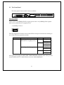
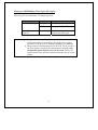
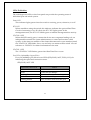
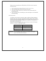
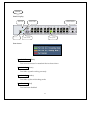
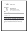
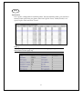
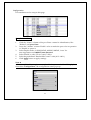
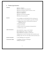
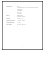
FCC Certifications
This Equipment has been tested and found to comply with the limits for a Class A
digital device, pursuant to part 15 of the FCC Rules. These limits are designed to
provide reasonable protection against harmful interference when the equipment is
operated in a commercial environment. This equipment generates, uses, and can
radiate radio frequency energy and, if not installed and used in accordance with the
instruction manual, may cause harmful interference to radio communications.
Operation of this equipment in a residential area is likely to cause harmful interference
in which case the user will be required to correct the interference at his own expense.
This device complies with Part 15 of the FCC Rules. Operation is subject to the
following two conditions: (1) this device may not cause harmful interference, and (2)
this device must accept any interference received; including interference that may
cause undesired operation.
CE Mark Warning
This equipment complies with the requirements relating to electromagnetic
compatibility, EN 55022 class A for ITE, the essential protection requirement of Council
Directive 89/336/EEC on the approximation of the laws of the Member States relating
to electromagnetic compatibility.
Company has an on-going policy of upgrading its products and it may be possible that
information in this document is not up-to-date. Please check with your local distributors
for the latest information. No part of this document can be copied or reproduced in any
form without written consent from the company.
Trademarks:
All trade names and trademarks are the properties of their respective companies.
Copyright © 2002, All Rights Reserved.
Document Version: 2.0
1
Table of Contents
1. Overview
2. Unpacking Information
3. Introduction to 24F.E.+2G.E. Gigabit Clustering Switch
3.1 General Description
3.2 Key Features
3.3 The Front Panel
Port Operation
Wiring for 10/100Mbps (Fiber Optical/Copper)
LEDs Definition
Power LED
RTC LED
STATUS 0 LED
STATUS 1 LED
Port LEDs (10/100Mbps Copper/Fiber Optical)
SPD/LINK/ACT LED
FULL/COL LED
LINK/ACT LEDs (For slide-in slots on the rear panel)
LINK LED (“STACK” port)
HUB ID
RESET button
3.4 The Rear Panel
Gigabit Slide-in slots
Gigabit Module Operation
Wiring for Gigabit Slide-in Module
Console Port
Power Receptacle
2
4. Installing 24F.E.+2G.E. Gigabit Clustering Switch
4.1 Desktop Installation
4.2 Rack-mount Installation
4.3 Installing Network Cables
Station Connections
Switch-to-Switch Connections
4.4 Module Installation
4.5 Management Stack
4.6 Network Application
5. Management Guide
5.1 Console Port (Out-of-Band) connection
5.2 In-Band Connections (Web Browser/ Telnet)
Starting a Telnet Session
Starting a Web Browser Session
Topology
System Configuration
Device
Panel Display
Port Status
Network Configuration
Device Information
Topology Info
Ports
Information
Configuration
Setup Port Attributes
Duplicate Port Attributes
Statistic
Location Search
VLAN
802.1Q VLAN
VLAN Static List
To create a new VLAN group
To remove a VLAN group
3
To modify a VLAN group
VLAN Static Table
To add member port
To remove member port
VLAN Port Configuration
To change the PVID
Port Group VLAN
All Together
All Independent
Port Aggregation
Priority
Address Table
MAC Address list
Configuration
To add a static address
To remove a static address
Mirror
6. Product Specifications
4
1.
Overview
The Gigabit Managed Cluster is a powerful, high-performance, high
port-density networking system, which can upgrade and integrate your existing
network from 10/100Mbps to a simplex, efficient, centralized management
environment and very high-speed network architecture. As all members operate
as teamwork, all connected members of the family are treated as a
Single-Managed device.
With its built-in rich, various and advanced management functions, system
administrator can monitor and control the whole system or individual port of any
members easily and remotely.
The members of the Gigabit Managed Cluster are:
24F.E.+2G.E Gigabit Clustering Switch
14+2G.E. Gigabit Clustering Switch
16V+2G.E. VDSL Clustering Switch
5
6
2.
Unpacking Information
Thank you for purchasing the 24F.E.+2G.E. Gigabit Clustering Switch. Before you
start, please check all the contents of this package.
The product package should include the following:
1. One 24F.E.+2G.E. Gigabit Clustering Switch
2. One power cord
3. Rubber foot and screws
4. Rack-mount brackets
5. User’s Manual
7
3.
Introduction to 24F.E.+2G.E. Gigabit Clustering Switch
3.1 General Description
The device is a 24+2-port 10/100/Gigabit Ethernet clustering switch with
twenty-four 10/100Mbps RJ-45 ports and two Gigabit slide-in slots on the rear
panel for optional fiber/copper Gigabit modules.
Compare to the traditional 10/100Mbps Ethernet, the switch delivers a dedicated
10/100Mbps connection to every attached client with no congestion issue. The
gigabit ports also provide the fat pipe to the server or backbone connectivity for
boosting the total system performance. Moreover, the NWay auto-negotiation
operation automatically negotiates with the connected partners on the network
speed and duplex mode; that provides an easy way to integrate 10 / 100 /
1000Mbps networks with no pain. It is ideal for micro-segmenting large networks
into smaller, connected subnets for improved performance, enabling the
bandwidth demanding multimedia and imaging applications.
Out of the ordinary dumb switches, the 24F.E.+2G.E. Gigabit Clustering Switch
embedded advanced management capability; that the device can be remote
managed by Telnet, SNMP manager and Internet browser. This is much useful for
system manager to monitor and control the system efficiently.
Store-and-forward switching mode promises the low latency plus eliminates all
the network errors, including runt and CRC error packets. To work under
full-duplex mode, transmission and reception of the frames can occur
simultaneously without causing collisions as well as double the network
bandwidth.
The switch is plug-n-play without any software to configure and also fully
compliant with all kinds of network protocols. Moreover, the rich diagnostic
LEDs on the front-panel provide the operating status of individual port and
whole system.
8
3.2 Key Features
Complies IEEE 802.3, IEEE 802.3u, IEEE802.3x, IEEE 802.3z/ab standards
Complies with IEEE802.1Q VLAN tag (IVL)
Complies with IEEE802.1p CoS with 2-level priority
The whole management stack can stack up to 8 sets
24 * RJ-45 ports for 10/100Mbps
2 * 1000Mbps Copper/Fiber slide-in slots
1 * 100Mbps Fiber slot (Alternative to copper port-1)
Proprietary management bus extend up to 800 meters for management stacking
Every switching port is automatically cross-over detection
(MDI/ MDI-X auto-detected)
Supports real-time clock (optional)
Supports IGMP snooping
Supports MIB counters
Supports port sniffering
Supports Port Aggregation and up to 7 groups
Supports port group VLAN and up to 255 groups
Supports 802.1Q VLAN and up to 255 groups
Supports 802.1D Spanning Tree
One RS-232 female console connector
Supports 8MB SDRAM for run time data storage
Supports 2MB Flash EPROM for cooperation and configuration data storage
Supports 6K MAC entries
Supports 3Mbit packet switching
19” rack mountable
Internal universal switching power supply
FCC Class A, CE
9
3.3 The Front Panel
The front panel of the switch is shown as below
Port Operation
There are 24 * 10/100Mbps RJ-45 (copper) ports with 1 * 10/100Mbps fiber optical
slide-in slot (Alternative to copper port-1).
--10/100Mbps Fiber SC
The auto-negotiation feature of the switch allows each port of the device running at
one of the following operation modes:
Port
Media
Speed
10/100Mbps 10/100Mbps fiber optical SC
(Alternative to copper port-1)
Duplex Mode
10Mbps Full Duplex
Half Duplex
100Mbps Full Duplex
Half Duplex
10/100Mbps RJ-45 (copper)
10Mbps Full Duplex
Half Duplex
100Mbps Full Duplex
Half Duplex
All copper ports supports MDI/MDI-X auto crossover capability that is the port can
connect either the PC or hub without crossover cable adjustment.
10
Wiring for 10/100Mbps (Fiber Optical/Copper)
Following are the summaries of cabling required:
Media
Speed
10/100Mbps copper 10Mbps
10/100Mbps
Fiber SC
Wiring
Category 3,4,5 UTP/STP
100Mbps
Category 5 UTP/STP
10/100Mbps
62.5/125 or 50/125µm
multi-mode fiber optic
Attention:1. Category 5 cable is preferred to use with this product in
structured wiring environments. This will ensure correct
operation of RJ-45 ports at 10Mbps, 100Mbps or 1000Mbps.
2. The proprietary management bus (“STACK” RJ-45 ports) on
the front panel is reserved for management stacking, only
straight-through UTP/STP cable can be used. There is no
Duplex Mode issue and the extended distance can up to 800
meters.
11
LEDs Definition
The rich diagnostic LEDs on the front panel can provide the operating status of
individual port and whole system.
Power LED
This indicator lights green when the switch is receiving power; otherwise, it is off.
RTC LED
When standalone using the switch, this indicator indicates the optional Real Time
Clock is functioning or not. If it does, the RTC LED lights green. In the
management stack, the RTC LED blinks green to indicate management bus activity
STATUS 0 LED
When this LED steady green, it means the device acts competent leading role, an
indispensable essential for system administrator to control and monitor whole
system. At the time one member of the cluster disconnected or new member joined,
the “STATUS 0” LED blinks. Soon, one and only one master will be raised. You can
reference to “HUB ID” for relative information in the next.
STATUS 1 LED
The “STATUS 1” LED flashes green when Run Time Error occurs.
Port LEDs (10/100Mbps Copper/Fiber)
Every 10/100Mbps port relevant two LEDs (SPD/LINK/ACT; FULL/COL) for
indicating the speed and connection status.
SPD/LINK/ACT LED
SPD/LINK/ACT LED
Status
Off
No Connection
Green
Connected as 100Mbps
Flashing Green
There is traffic transverses the port
Amber
Connected as 10Mbps
Flashing Amber
There is traffic transverses the port
12
If the port is connected but the SPD/LINK/ACT LED is dark, check the
following items:
1. The switch and the connected device’s power are on or not.
2. The connecting cable is good and with correct type
3. The cable is firmly seated in its connectors in the switch and in the
associated device
4. The connecting device, including any network adapter is well installed
and functioning
FULL/COL LED
A collision occurs when two stations within a collision domain attempt to
transmit data at the same time. Intermittent flashing amber of the collision
LED is normal; the contending adapters resolve each collision by means of a
wait-then-retransmit algorithm. Frequency of collisions is an indicator of
heavy traffic on the network.
If the FULL/COL LED lights amber, means the port is under Full-Duplex
operation or dark for Half-Duplex mode.
FULL/COL LED
Status
Steady Amber
Full-Duplex mode
Dark
Half-Duplex mode
Flashing Amber
Collision
Attention:The 10/100Mbps fiber optical SC slot shares with copper
port-1 in the same LED indicators
13
LINK/ACT LEDs (For slide-in slots on the rear panel)
The slide-in slot has a LINK/ACT LED itself. When one slide-in module is well
installed and functioning, the relevant one lights green.
LINK LED (“STACK” port)
The LED lights green, when a management stack is made via the “STACK” port
and negotiates with associated devices successfully.
HUB ID(Rotary Switch)
All members of the management stack are ranked according to their “HUB ID”(Device
ID). There are eight degrees (0~7) in the rotary switch. The smaller number, the higher
degree. Device with smallest “HUB ID” will be the “Master” device. Then, system
management can perform by the way of the “Master Device”.
Attention:Every device in the management stack should have a unique
“HUB ID”. In the meanwhile, a “HUB ID” which has been
using by a device, reused by another, the management stack
will fail.
RESET Button
The system will reboot when “RESET” button is pressed.
14
3.4 The Rear Panel
The rear panel of the switch is shown as below
Gigabit Slide-in slots
The two slide-in slots on the rear panel are reserved for following optional gigabit
modules. They can provide fat pipes for up linking to backbone or connecting to
servers.
--Gigabit Fiber SC
--Gigabit Copper
Gigabit Module Operation
Port
Media
Speed
Duplex Mode
Gigabit port
Gigabit RJ-45 port
10Mbps
Full Duplex
Half Duplex
100Mbps
Full Duplex
Half Duplex
1000Mbps Full Duplex
Gigabit Fiber SC
1000Mbps Full Duplex
15
Wiring for Gigabit Slide-in Module
Following are the summaries of cabling required:
Media
Speed
Wiring
Gigabit copper
10Mbps
Category 3,4,5 UTP/STP
100Mbps
Category 5 UTP/STP
1000Mbps
Category 5 UTP/STP
1000Mbps
62.5/125 or 50/125µm
multi-mode fiber optic
Gigabit Fiber SC
Console Port
The RS-232 console is an interface for connecting a terminal directly. Through
the console port, it provides rich diagnostic information includes network
statistics, link status and system setting. The operating mode of the console
port is:
DCE
9600 (Fix baud rate)
n (No parity checking)
8 (8 Data bits)
1 (1 stop bit)
None (No flow control)
You can use a normal RS-232 cable and connect to the console port on the device. After
the connection, you can run any terminal emulation program (Hyper Terminal,
Winterm, Telix, … and so on) to enter the startup screen of the device. All the detail
software operation, please refer to “Console port (out-of-band) connection” session of
chapter 5.
16
Power Receptacle
For compatibility with electric service in most areas of the world, the switch’s power
supply automatically adjusts to line power in the range 100-240 VAC and 50-60 Hz.
Plug the female end of the power cord firmly into the receptacle on the rear panel of
the switch. Plug the other end of the power cord into an electric service outlet then the
power will be ready.
17
4.
Installing 24F.E.+2G.E. Gigabit Clustering Switch
This switch can be placed directly on your desktop, or mounted in a rack. If you
install the device in a normal-standalone standard, the switch is an Intelligent
Switch, and users can immediately use most of the features simply by attaching
the cables and turning the power on. In this case, any managerial proceedings are
effective only in the range of the switch. After management stacking, you can
enjoy the powerful management functions and control the whole system.
4.1 Desktop Installation
For desktop installation, the switch needs to put on a clean, flat desk or table close
to a power outlet. Plug in all network cables and the power cord, then the system
is ready.
Before installing the switch, you must ensure:
1.
2.
3.
4.
It is accessible and cables can be connected easily
Cabling is away from:
*Sources of electrical noise such as radios, transmitters and broadband
amplifiers
*Power lines and fluorescent lighting fixtures.
Keep water or moisture off
Airflow around the unit and through the vents in the side of the case is great
for heat radiation (company recommend that you provide a minimum of 25
mm clearance)
To prolong the operational life of your units:
1.
2.
3.
Never stack unit more than eight sets high if freestanding
Do not place objects on top of any unit or stack
Do not obstruct any vents at the sides of the case
18
4.2 Rack-mount Installation
The switch may standalone, or may be mounted in a standard 19-inch equipment
rack. Rack mounting produces an orderly installation when you have a number of
related network devices. The switch is supplied with rack mounting brackets and
screws. These are used for rack mounting the unit.
Rack Mounting the Switch in the 19-inch rack:
1.
2.
3.
4.
5.
6.
7.
Disconnect all cables from the switch before continuing.
Place the unit the right way up on a hard, flat surface with the front facing
toward you.
Locate a mounting bracket over the mounting holes on one side of the unit.
Insert the screws and fully tighten with a suitable screwdriver.
Repeat the two previous steps for the other side of the unit.
Insert the unit into the 19" rack and secure with suitable screws (not
provided).
Reconnect all cables.
19
4.3 Installing Network Cables
After placing the switch on the desktop, we need to know how to connect the
device to network.
Station Connections
Reference to the wiring statement of the previous section; connect each station to the
switch with correct type of cables.
Switch-to-Switch Connections
In making a switch-to-switch connection, use Gigabit ports to connect another switch
or backbone is strongly recommended. The Gigabit ports provide the fat pipe to the
server or backbone connectivity for boosting the total system performance. Reference
to the wiring statement of the previous section; connect each station to the switch with
correct type of cables.
Furthermore, as the switch supports port aggregation (port-trunk) capability and up to
7 groups, it is also great to build up switch-to-switch connectivity. For detail
information, please reference to the “Management Guide” session.
4.4 Module Installation
The three slide-in slots on the front and rear panel are purposed for installing
optional modules. They can be used as a network backbone or connect to a server.
Follow the steps as described to install a module:
1.
2.
3.
4.
Power off the switch
Removing the two screws on the face plate of slide-in slot with a flat-head
screwdriver
Push the module gently into the slot along the slide tracks
Ensuring that it firmly engages with the connector then tighten the screws to
secure the module
Attention:The slide-in slots are not hot swappable, power off the switch
before installing modules
20
4.5 Management Stack
There are two RJ-45 ports on the front panel for proprietary management stack.
Only straight-through UTP/STP cable can be used.
Plug one end of the cable in the “IN” port and the other end to the ”OUT” port of
next device. Repeat the step for every device in the cluster, then ending at last
switch.
Attention:Before management stacking, be sure of every device uses a
unique “HUB ID”, or the management stack will not work
21
4.6 Network Application
22
5.
Management Guide
This section instructs you how to enter and proceed the advanced management
capability, which can be accessed by RS-232 serial port (out-of-band) on the rear panel
or by Telnet session / Internet Browser over the network (in-band).
The management functions such as:
·
·
·
·
·
Port Information/configuration/Statistic/Location Search/Duplex mode/Flow
Control
SNMP parameters
802.1Q/Port Group VLAN
Upgrade system firmware
Reboot system
5.1 Console Port (Out-of-band) connection
After attaching a RS-232 cable (Straight-through) to the serial port of a PC
running a terminal emulation program, press “Enter” key then login
screen appears. Enter your username and password to login the
management console.
Note:
The management functions of console program are exactly the same with
web-based management interface but in text mode. For further operation, please
refer to ’Starting a Web Browser Session’.
Attention:1. The factory default value of UserName and Password is
“admin”
2. For detail console port configurations, please refer to
“Console Port” in chapter 3
3. System configurations via the Console Port only will be
allowed by the way of master device
23
5.2 In-Band Connections (Web Browser / Telnet)
To manage the switch through in-band access, you should configure the
management station with an IP address and subnet mask compatible with
your clustering switch.
Factory Default value:
10.0.0.1
IP:
Subnet Mask:
255.0.0.0
Default Gateway: 10.0.0.254
Both standalone switch and the cluster can be managed using either a
standard Web Browser or a Telnet session from any computer attached to
the network. The SNMP management feature also permits the switch to be
managed from any SNMP network management station running a
network management program.
To manage the Standalone switch:
Access the switch with its IP address “10.0.0.1” (factory default value)
To manage any of the Clustering switch:
Access the switch with the IP address of Master device in the
management stack. Then select the switch you want to manage in the
first page
Starting a Telnet Session
To access the switch through a Telnet session:
1.
Sure of the switch is configured with an IP address and the switch is
reachable from a PC
2.
Start the Telnet program on a PC and connect to the switch
Note:
The management functions of Telnet program are exactly the same with
web-based management interface but in text mode. For further operation, please
refer to ’Starting a Web Browser Session’.
24
Starting a Web Browser Session
This Web Browser User Interface is coded by Java Applet and running on the JavaTM
Virtual Machine (JVM) version 1.3.1 platform. You should configure the management
station with an IP address and subnet mask compatible with your clustering switch for
accessing it. Also, the management station should be well configured and connected to
Internet for automatically downloading (upgrading) the suitable JVM through Internet
from “http://java.sun.com”. Or you can download it yourself by the URL
“http://java.sun.com/j2se/1.3/download.html” and then manually install it.
Attention:Occasionally the newer JavaTM Virtual Machine is not
backward compatible, that JVM version 1.3.1 is strongly
recommended to ensure properly operation
Running your Web Browser and enter the IP address “10.0.0.1” (When your switches
are in a well-installed management stack, remember that the portal IP address will be
vary with your actually management topology) as the URL in the “address” field.
After authentication procedure, the home page shows up. In this page, you can view
the management stack topology or standalone switch.
25
Topology
This screen displays one or more switches of the management stack. Basic
properties can be read by the screen, include Hardware characteristic, Device
Name, Device Up time, Master and Slave relationship. Also, by mouse clicking
listed items can enter for further operation.
System Configuration
If you are managing a Master or a Standalone device, the system configuration
parameters are equal to parameters of Net Configuration and Device Information
in Device tab. For further information, please refer to Device statement.
26
After clicking the 24F.E.+2G.E. Gigabit Clustering Switch, main screen shows up.
Function
Statement
<Home>
Shortcut to back to home page
<Save>
Save the current setting to Non-volatile Memory. The difference
between <Save> and <Apply> is that Apply applies settings right away
but saves the values in the system memory. Every time when switch
reboots, system obtains system parameters from Non-volatile Memory
you <Saved> before but not buffer memory.
Select the one(s) you want to save parameters, then click “Save” button
to save it to Non-volatile Memory.
<Default>
Make the switch(es) returning to factory default value. Select the switch
and click “Default” button, the selected-switch(es) will return to initial
value. If you want to clear the previous value in the Non-volatile
Memory, please <Save> it.
27
<Reboot>
You can specify switch(es) and reboot it.
Warm Boot Reboot the switch in a short time.
Cold Boot
Boot the switch and with fully Power On Self Test
(POST). The system is completely checked but spend
much time.
<Ping>
The Ping is a commonly used tool to detect the remote host or IP
address exists or not. Moreover, network status also can be known by
the ratio of packets Reply and Loss.
<Telnet>
By simply clicking the <Telnet> button, the Telnet program
implements and displays login screen.
<Contact>
Contact technicians for technical support by E-Mail
28
<Upgrade>
WEB Upload
1. Select Device ID and “WEB Upload” radio button then click OK
2. Specify the file path by clicking Browse button and click Start
TFTP Download
1. Select Device ID and “TFTP Download” radio button then click
OK
2. Enter the TFTP server’s IP address in Server IP field
3. Enter file name in File Name field
4. Click Start button to download the code and system update with it
automatically
Local File Transfer
1. Select Device ID and “Local File Transfer” radio button then click
OK
2. Click “Application” or ”Java Applet” radio button
29
3.
The system starting software synchronization from Master Device
(That the synchronized hardware should be identical to Master
Device)
Application --- System firmware
Java Applet --- Web User Interface
<Device:>
The shortcut to go to another member switch in the management stack
30
Device
Panel Display
RTC LED
HUB ID
Status 0 LED
Slide-in Modules
Status 1 LED
RJ-45 ports
Port Status
Port Link Down (Black)
Port is not connected or attached device shuts down
Port Link Up (Green)
Port links up and working correctly
Port Link Up (Amber)
Port links up but in blocking mode
Port Disabled (Red)
Port has been disabled
31
Network Configuration
IP Address
IP address of this device
Subnet Mask
NetMask of your network
Gateway IP
IP address of Gateway
Device Information
Name
Naming the system (optional)
Contact
Who the System administrator is (optional)
Location
Where the management stack locates (optional)
Note:
The Network Configuration and Device Information of Master Device in the
management stack will become system parameters automatically.
Topology Info
This page displays information about the switch(es), such as Device ID, Hardware
version, Boot-Up version, POST version, Runtime version (Firmware version), JAVA
Applet version (Web User Interface version), Device Name and Device Location.
When management stack persist, by the Device ID, all the members are transparently
listed.
32
Ports
Information
It is a ports’ configurations summary table. Via the summary table, you can know
status of each port clear at a glance, like Link Up/Link Down, Enable/Disable, Link
Speed, Duplex mode and Flow Control.
Note:
Also by simply clicking the port on the ‘Panel Display’, the port
information screen pops up
33
Configuration
Port attributes can be setup in this page.
Setup Port Attributes
1.
2.
3.
4.
5.
6.
Click the “Name” column of the port. Enter a name for identification, like
‘Richard’; and press Enter
Leave the “Admin” column ‘Enable’ value to make the port to be in operation
or ’Disable’ to pause it
Select Duplex mode---10Half/10Full; 100Half/100Full, ‘Auto’ for
auto-negotiation and 1000Full auto-detection
Select ‘Enable’ to take “Flow Control” effect
Select the predefined “Bandwidth Control” scale (10%~100%)
Click Apply button to apply settings
Note:
Also accomplished by simply mouse right-click the port on the ‘Panel Display’
then select ‘Configuration’, the configuration screen pops up
34
Flow Control operation mode:
Speed / Duplex mode
Flow Control
10Half
Back pressure
100Half
Back pressure
1000Half
Back Pressure
Speed / Duplex mode
Flow Control
10Full
IEEE 802.3x Pause Frame
100Full
IEEE 802.3x Pause Frame
1000Full
IEEE 802.3x Pause Frame
35
Duplicate Port Attributes
Click “Duplicate” button, the dialogue screen appears.
1.
2.
3.
4.
5.
6.
Select Source Port (for example Port 2)
Select Target Port, click All for select all (for example Port 8, 9, 10)
Select the port attributes you want to duplicate
Click OK to submit values
Click Apply button to apply settings
As the following result, port 2 is duplicated to port 8, 9, 10 accompany with
specified attributes.
Note:
Also accomplished by simply mouse right-click the port on the ‘Panel Display’
then select ‘Copy Setting’ to duplicate port properties and select ’Past Setting’
when point at destination port
36
Statistic
Ether Like Frame Types
RX Bytes
RX Frames
RX crc_err
TX Byte
TX Frames
TX Collisions
TX drops
TX underruns
Number of bytes received in good and bad frames
Number of good and bad packets received
Number of CRC errors received
Number of bytes transmitted in good and bad frames
Number of good and bad packets transmitted
Number of collisions on transmitted frames
Frames dropped due to lack of receive buffer
Increments when packet transmission fails due to the
inability of the interface to retrieve packets from the local
packet buffer fast enough to transmit them onto the
network
RX Good Frame Types
RX Bytes
RX frames
RX broadcasts
RX multicasts
RX less64_pkts
RX 65to127_pkts
RX 128to255_pkts
RX 256to511_pkts
RX 512to1023_pkts
RX 1024more_pkts
Number of bytes received in good and bad frames
Number of good and bad packets received
Number of good broadcasts
Number of good multicasts
Number of short frames with invalid CRC (<64 bytes)
Number of 65 to 127-bytes frames in good and bad
packets
Number of 128 to 255-bytes frames in good and bad
packets
Number of 256 to 511-bytes frames in good and bad
packets
Number of 512 to 1023-bytes frames in good and bad
packets
Number of 1024 to max-length-type frames in good and
bad packets
37
RX Error Frame Types
RX alignment_err
Number of alignment errors received
RX crc_err
Number of CRC errors received
RX oversize_err
Number of long frames with valid CRC
RX undersize_err
Number of short frames with valid CRC
RX fragments_err
Number of short frames with invalid CRC
RX jabbers_err
Number of long frames with invalid CRC
Location Search
A denominate port can be searched by its given name. (Match whole word only)
38
VLAN
The VLAN is a group of ports that may spread around the network but communicate
as though they belong to one subnet. By using IEEE 802.1Q compliant VLAN, all ports
can be reorganized into separate broadcast domains for security reasons and reduce
bandwidth occupation instead of using routers to divide whole network into subnets.
It produces cleaner network environment by reducing broadcast traffic and simplify
network management by allowing you to move devices to another VLAN without
changing physical connections.
802.1Q VLAN
Before enabling 802.1Q VLAN , pay attention to:
·
·
All ports are default to VLAN 1 and assigned PVID 1
All the ports of a Aggregation Group must to be treated as an integer when
added to/deleted from a VLAN
VLAN Static List
This screen is used to Add / Remove / Modify VLAN and up to 255 groups.
The VLAN groups that have been created are all listed here.
To create a new VLAN group
1.
2.
3.
4.
Specify the name for the new VLAN group (VLAN name is only used for
identification)
Enter a number (VLAN ID) for the new VLAN group
Check the “Active” box to activate the VLAN or leave it blank and
activate it afterward
Click <<Add button to create the new VLAN
39
To remove a VLAN group
1.
2.
Select a VLAN group you want to remove from the “Current” list
Click Remove>> button to remove it
Attention:1. If a removed port is no longer belong to any other group, it is
temporarily disabled because no one can communicate with
it.
2. If one port’s PVID is equal to this VLAN ID, removing this
VLAN group will not allow until you change it.
To modify a VLAN group
1.
2.
3.
Select a VLAN group you want to remove from the current list
Modify parameters in “New” column
Click Modify button to submit the new parameters
VLAN Static Table
This screen is used to Add/Remove member ports of a VLAN.
Egress Ports/Member
The ports that have been added to the displayed VLAN group
Tagged Ports/Member
The tagged ports of the displayed VLAN group
40
To add member port
1.
2.
3.
Click the “VLAN ID” combo box and select a VLAN you want new ports
to join in
Select ports (press Shift/Ctrl key for selecting multi ports) in the
“Non-Member” column
Click <<Add button to join selected ports in
To remove member port
1.
2.
3.
Click the “VLAN ID” combo box and select a VLAN you want to remove
ports
Select ports (with Shift/Ctrl key to select multi ports) in the “Member”
column
Click Remove>> button to delete selected ports
Note:
1. If a removed port is no longer belong to any other group, it is
temporarily disabled because no one can communicate with it
2. The port which is assigned a PVID and the PVID is equal to
VLAN ID, removing the port will not allow until you change it
VLAN Port Configuration
When the VLAN-enabled switch receives an untagged packet, the packet will
be sent to the port’s default VLAN according to the PVID (port VLAN ID) of
the receiving port.
41
To change the PVID
1.
2.
3.
4.
Double click the “PVID” column of a port
Input a new VLAN ID (1~255)
Press “Enter” to submit the value
Click Apply button to apply it
Note:
1. All the ports are default as members of VLAN 1 and assigned PVID 1
2. The port which was assigned a PVID and the PVID is equal to VLAN
ID, removing the port will not allow until you change it
3. Automatically, a port will join the VLAN of its PVID, and if the
VLAN does not exist, system will create it
To Enable/Disable Ingress Filtering
When one packet comes in from Port X to VLAN Y, but Port X is not a
member of VLAN Y
Ingress Filter Enabled:The filter checks the packet and detects Port X does
not belong to the VLAN Y, the Ingress Filter discards
the packet.
Ingress Filter Disabled:All the packets destined to VLAN Y are all
unobstructed.
Click the “Ingress Filtering” column of a port and select ‘Enable’ to activate
Ingress Filter
42
Port Group VLAN
The Port Group VLAN (Port-based VLAN) is concentrate on definite ports. The
packets forwarding policies are based on destination MAC addresses or related
ports by voluntary learning relationship of MAC addresses and its related ports.
All Together
Click All Together
to VLAN group 1
button then all the ports of the switch will be added
All Independent
Click All Independent button then all the ports will be divided into
separated subnets, that are 26 subnets
Every port can belong to different Port Group VLANs simultaneously without
limitation.
43
Port Aggregation
Port Aggregation (Port Trunk) is used to increase the bandwidth of a switch-to-switch
connection and backup. This switch provides 7 port aggregation groups, which consist
of 4 ports and create bandwidth up to 800Mbps per group (the group 6 consists of 2
slide-in slots and creates bandwidth up to 4Gbps) at full duplex mode. Check the box
of Aggregation Group in the Status Enable column and press “Apply” then the
selected Aggregation Group is activated.
However, before making connections between switches, pay attention to:
· The ports at both ends of a Port Aggregation connection must be configured as
Aggregation Ports
· The ports at both ends of a Port Aggregation connection must have the same port
properties, including Speed, Duplex mode
· All the ports of a Port Aggregation must to be treated as an integer when added
to/deleted from a VLAN
· Spanning Tree Algorithm (STA) treats all the ports of a Port Aggregation as an
integer.
· Before connecting cables between switches, enable the Pot Aggregation to avoid
looping
· Before disabling Port Aggregation, remove the connecting cables between switches
to avoid looping
· Both two slide-in slots should use the identical modules (two coppers/two fibers)
otherwise the Port Aggregation connection is invalid
·
44
STA
The Spanning Tree Algorithm (STA) outlined in IEEE 802.1D can avoid network
looping but coexist with linking backup. This feature permits STA-aware switches
interact with each other. This can ensure only one route exists between any two
devices on the network. If looping is detected (maybe implements on purpose for
linking backup), looping ports will be blocked to discard additional route. If one using
route fails, this Spanning Tree Algorithm automatically releases the blocking port and
establishes connection with other devices.
Since a STA network has been established, all devices listen for Hello BPDUs (Bridge
Protocol Data Units) sent from the Root Bridge. After the Max Age maximum time is
up, the device supposes that the route to the Root Bridge is down. The devices initiate
negotiations with each other to reconfigure the network for a valid topology.
Root Device
Designated Port
Designated Port
Root Port
Designated Port
Root Port
Root Port
Blocking Route
Root Port
45
Designated Port
Root Port
Information
This screen displays summaries of STA information. For further configuration,
please go to next session.
Parameter
STA State
Description
Shows if STA is enabled on the switch and
participated an STA compliant network
Designated Root
Bridged ID
Root Port
Max Age
(6~40 sec)
The unique Bridge Identifier of the Bridge recorded
as the Root in the Configuration BPDUs transmitted
by the Designated Bridge for the segment to which
the port is attached
The MAC address used by this bridge when it must
be referred to in a unique fashion. It is
recommended that this be the numerically smallest
MAC address of all ports that belong to this bridge.
However it is only required to be unique
The port number of the port which offers the lowest
cost path from this bridge to the root bridge
The maximum age of Spanning Tree Protocol
information learned from the network on any port
before it is discarded, in units of a second. This is
the actual value that this bridge is currently using
46
Hello Time
(1~10 sec)
Hold Time
Forward Delay
(4~30 sec)
Root Path Cost
Configuration Changes
Last Topology Change
The amount of time between the transmission of
Configuration bridge PDUs by this node on any
port when it is the root of the spanning tree or
trying to become so, in units of a second. This is the
actual value that this bridge is currently using
This time value determines the interval length
during which no more than two Configuration
bridge PDUs shall be transmitted by this node, in
units of a second
This time value, measured in units of a second,
controls how fast a port changes its spanning state
when moving towards the Forwarding state. The
value determines how long the port stays in each of
the Listening and Learning states, which precede
the Forwarding state. This value is also used, when
a topology change has been detected and is
underway, to age all dynamic entries in the
Forwarding Database
The cost of the path to the root device as seen from
this bridge
The total number of topology changes detected by
this bridge since the management entity was last
reset or initialized
The time (in a second) since the last time a topology
change was detected by the bridge entity
47
Configuration
Usage
Enable/Disable this switch to join in/withdraw from a
STA compliant network
Priority
(1~65535)
Priority is a decisive key for selecting root device, root
port, and designated port. The smaller number, the higher
priority. The device with the highest priority becomes the
STA root device. However, if all devices have the same
priority, the device with the lowest MAC address will
become the root device
Hello Time
(1~10sec)
Maximum
Age
(6~40sec)
Forward
Delay
(4~30sec)
The amount of time between the transmission of
Configuration bridge PDUs by this node on any port
when it is the root of the spanning tree or trying to
become so, in units of a second. This is the actual value
that this bridge is currently using
The maximum age of Spanning Tree Protocol
information learned from the network on any port
before it is discarded, in units of a second. This is the
actual value that this bridge is currently using
This time value, measured in units of a second,
controls how fast a port changes its spanning state
when moving towards the Forwarding state. The
value determines how long the port stays in each of
the Listening and Learning states, which precede the
Forwarding state. This value is also used, when a
topology change has been detected and is underway,
to age all dynamic entries in the Forwarding Database
48
STA Port Configuration
Priority
Path Cost
Fast Forward
The value of the priority field which is contained in
the first (in network byte order) octet of the (2 octet
long) Port ID
The contribution of this port to the path cost of paths
towards the spanning tree root, which include this
port. 802.1D-1990 recommends that the default value
of this parameter be in inverse proportion to the speed
of the attached LAN
The device omits from the 4 steps
(Blocking-Listening-Learning-Forwarding) to 3 steps
(Blocking-Listening-Forwarding) for speeding up
specified port to be running when STA topology has
been changed
49
Priority
This switch supports IEEE802.1p CoS with 2-level priority. There are 8 traffic classes
and 8 Service Rules in the Priority Map. When one packet carries with priority-tag,
which has specified a CoS (Class of Service) comes into the switch, the specified CoS
tag will determine what priority (Low/High) will it get according to the Priority Map
in the switch.
Service Rule
FIFO
The first in packet, the first out packet (No priority)
1:1
Send 1 high priority packet, then 1 low priority packet
2:1
Send 2 high priority packets, then 1 low priority packet
3:1
Send 3 high priority packets, then 1 low priority packet
4:1
………..
5:1
………..
6:1
………..
7:1
Send 7 high priority packets, then 1 low priority packet
50
Address Table
The address table is the learning table, which is composed of many entries and is the
most important base to do packet filtering and forwarding.
MAC Address List
Choose the port you preferred to view the address table and click “Refresh” button,
the MAC address table will be list.
Configuration
Dynamic Address Counts
Number of MAC addresses automatically
learned by the current clustering switch
Static Address Counts
Number of MAC addresses manually
added to the current clustering switch
To add a static address
1.
2.
Click the combo box and select a port, then the MAC address table of the port
appears
Fill in configuration value (VLAN ID, MAC address), then click “<<Add” button
(Note that ports on the switch are all default to VLAN 1)
Note:
The ports of Port Aggregation Group can not be added in Static Address
table
51
To remove a static address
1.
2.
Click the static address in the MAC address table of the port
Click “Remove>>” button to remove it from MAC address table
Mirror
Port mirror is used to mirror traffic from source port to a target port for analysis. Only
2 ports can be monitored (mirrored) simultaneously to 1 sniffer port (target port).
(Note that the target port must be in the same VLAN as the source port)
1.
2.
3.
4.
Click “Active” radio button to activate port mirror
Select ‘Monitored Ports’ (up to 2 ports)
Click ‘Sniffer Port’ combo box and select a sniffer port (target port) and click
“Apply” to apply
This figure describes port 2 and port 3 will be mirrored to port 11
52
6.
Product Specifications
Standard
IEEE802.3 10BASE-T
IEEE802.3u 100BASE-TX/100BASE-FX
IEEE802.3x full-duplex operation and flow control
IEEE802.3ab 1000BASE-T
IEEE802.3z 1000BASE-SX
IEEE802.1Q VLAN interoperability
IEEE802.1p Priority Operation
Interface
24 * 10/100Mbps auto MDI/MDI-X RJ-45 switching ports
2 * slide-in slots for optional gigabit copper/fiber modules
1 * 100Mbps slide-in slot for optional fiber module and
alternative to port 1
1 * RS-232 console port
1 * system reset button
2 * RJ-45 connectors for proprietary management bus
1 * HUB ID rotary switch
Cable Connections
RJ-45 (10BASE-T): Category 3,4,5 UTP/STP
RJ-45 (100BASE-TX): Category 5 UTP/STP
RJ-45 (1000BASE-T): Category 5, 5e UTP/STP
100Mbps fiber: 62.5/125 or 50/125µm multi-mode fiber optic
1000Mbps fiber: 62.5/125 or 50/125µm multi-mode fiber optic
Network Data Rate
10/100/1000Mbps Auto-negotiation
Transmission Mode
10/100Mbps Full-duplex, Half-duplex
1000Mbps Full-duplex
53
LED indications
System
Power; RTC; Status 0; Status 1; Link (management stack)
10/100Mbps Port
SEED; ACT
Slide-in slot
LINK; ACT
Memory
6K MAC entries
3Mbit packet switching
Emission
FCC Class A, CE
Operating Temperature
00 ~ 500C (320 ~ 1220F)
Operating Humidity
10% - 90%
Power Supply
100~240 VAC, 50~60 Hz
54