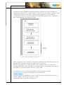
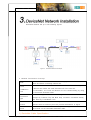
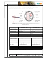
1
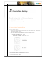
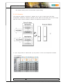
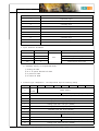
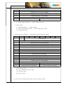
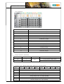
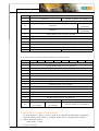
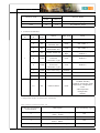
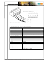
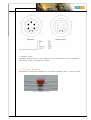
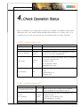
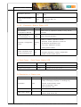
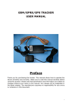
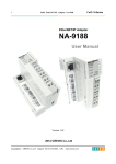
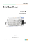
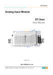
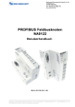
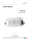
NA-9111 / NA-9112
User Manual
Copyright(C) * CREVIS Co.,Ltd * Support +82-31-273-6452 * URL : www.crevis.co.kr
- 1-
NA-9111 / NA-9112
User Manual
List of revisions
No.
1
Date
2007. .
Version
1.00
Revision
created
Copyright(C) * CREVIS Co.,Ltd * Support +82-31-273-6452 * URL : www.crevis.co.kr
- 2-
NA-9111 / NA-9112
User Manual
Contents
1. Product Specification
1) General Specifications
2) DeviceNet Communication Specification
2. DeviceNet Setting
1) Communication parameter setting
2) I/O allocation
3) DeviceNet I/O Data Format setting
4) EDS & I/O Module setting
3. DeviceNet Network Installation
1) DeviceNet Cable Specification
2) DeviceNet Connector
3) Terminating resistors
4. Check Operation Status
1) MOD : Module Status LED
2) NET : Network Status LED
3) I/O : Expansion Module Status LED
4) Field Power : Field Power Status LED
5) Description of Status Byte
Copyright(C) * CREVIS Co.,Ltd * Support +82-31-273-6452 * URL : www.crevis.co.kr
- 3-
NA-9111 / NA-9112
User Manual
1) General Specifications
Item
Temperature
Humidity
Specifications
Operating
-0℃ to +60℃ (32℉ to 140℉)
Storage
-40℃ to +85℃ (-40℉ to 185℉)
Operating
5 to 95% RH (Non-condensing)
Storage
5 to 95% RH (Non-condensing)
Vibration immunity
Shock Immunity
Capsuling
Remarks
10 TO 55Hz,double amplitude of 0.75mm,
10minutes on each of 3 axes (X,Y,Z)
Peak acceleration and duration 15g/11ms,
3 times on each of 3 axes (X,Y,Z)
Din rail or screw tightening
2) DeviceNet Communication Specification
Item
Specification
Remarks
Network Protocol
I/O Slave Messaging (Group 2 Only slave)
- Poll command : yes
- Bit_STROBE command : yes
- Cyclic command : yes
- COS command : yse
Network length
Max.500Meter (125Kbps)
Max.250Meter (250Kbps)
Max.100Meter (500Kbps)
Number of Nodes
64 Node/Max
Rotary switch
Communication speed
125Kbps, 250Kbps, 500Kbps
Auto Baudrate
selection
Number of Expansion I/O Max. 32 Slots
Isolation
Non-Isolation (DeviceNet to Logic)
DeviceNet Power
Rate voltage: 24V DC nominal Voltage range:
11 to 28.8 V DC Current consumption: Max
1.5w
Copyright(C) * CREVIS Co.,Ltd * Support +82-31-273-6452 * URL : www.crevis.co.kr
- 4-
NA-9111 / NA-9112
User Manual
DeviceNet setting include the following configurations:
- Communication parameter setting
- I/O allocation
- DeviceNet I/O Data Format Setting
- EDS & I/O Module setting
1) Communication Parameter Setting
◆ Node Address Setting
- NA-9111/9112 Node address is determined by the node address rotary switch on the
front panel of adapter module.
- Set node address is recognized on the power-on of adapter module.
Ex) When node address is set as 27:
Device MAC ID Setting :( 2*10 + 1*7 )= 27
* Each DeviceNet Adaptor has MAC ID from no.0 to 63
◆ Communication Speed Setting
Copyright(C) * CREVIS Co.,Ltd * Support +82-31-273-6452 * URL : www.crevis.co.kr
- 5-
NA-9111 / NA-9112
User Manual
- See Master Setting about communication speed setting.
2) I/0 Allocation
The expansion Module connecting to Adaptor has 3 types of Data types (I/O Data,
Configuration Parameters, Memory Resister) These data are exchanging I/O Process image
Data via FnBus Protocol between Adaptor and Expansion Module as below ;
◆ Input Image Data is determined by the position of Slot and Expansion Module.
= For Example
Slot Address
Module Description
Copyright(C) * CREVIS Co.,Ltd * Support +82-31-273-6452 * URL : www.crevis.co.kr
- 6-
NA-9111 / NA-9112
User Manual
0
DeviceNet Adaptor
1
4-Discrete input
2
8-Discrete input
3
2-Analog input
4
16-Discrete input
5
4-Discrete input
6
8-Discrete input
7
4-Discrete input
8
2-Analog input
9
16-Discrete input
10
4-Discrete input
◆ Input Instance Attributes
Instance ID
Attribute ID
100
3
101
3
102
3
103
3
Access Rule
Description
Status+Uncompressed Input Data
Status+compressed Input Data
Get
Uncompressed Input Data
Compressed Input Data
● Assembly Priority of Compressed Mode :
1) Analog IO Data
2) 8 or 16 points Discrete IO Data
3) 4 points IO Data
4) 2 Points IO Data
◆ Instance type 100(Status + Uncompressed Input Processing Data)
Byte
0
1
Bit7
Bit6
Bit5
Field
Bit4
Bit3
Bit2
Reserved
Discrete Input 4 pts (Slot#1)
Discrete Input 8 pts (Slot#2)
3
Analog Input CH0 low byte (Slot#3)
4
Analog Input CH0 high byte (Slot#3)
5
Analog Input CH1 low byte (Slot#3)
6
Analog Input CH1 high byte (Slot#3)
7
Discrete Input low 8 pts (Slot#4)
8
Discrete Input high 8 pts (Slot#4)
Reserved
10
11
12
Bit0
FnBus Status
Power
2
9
Bit1
Discrete Input 4 pts (Slot#5)
Discrete Input 8 pts (Slot#6)
Reserved
Discrete Input 4 pts (Slot#7)
Analog Input CH0 low byte (Slot#8)
Copyright(C) * CREVIS Co.,Ltd * Support +82-31-273-6452 * URL : www.crevis.co.kr
- 7-
NA-9111 / NA-9112
User Manual
13
Analog Input CH0 high byte (Slot#8)
14
Analog Input CH1 low byte (Slot#8)
15
Analog Input CH1 high byte (Slot#8)
16
Discrete Input low 8 pts (Slot#9)
17
Discrete Input high 8 pts (Slot#9)
18
Reserved
Discrete Input 4 pts (Slot#10)
● Field Power :
0 : 24Vdc Field Power On, 1 : 24Vdc Field Power Off
● FnBus Status :
0 : Normal Operation, 1 : FnBus Standby
2 : FnBus Communication Fault, 3 : Slot Configuration Failed
4 : No Expansion Slot
◆ Instance type 101(Status + compressed Input Processing Data)
Byte
Bit7
0
Field
Power
Bit6
Bit5
Bit4
Bit3
Bit2
Bit1
Bit0
FnBus Status
1
Analog Input CH0 low byte (Slot#3)
2
Analog Input CH0 high byte (Slot#3)
3
Analog Input CH1 low byte (Slot#3)
4
Analog Input CH1 high byte (Slot#3)
5
Analog Input CH0 low byte (Slot#8)
6
Analog Input CH0 high byte (Slot#8)
7
Analog Input CH1 low byte (Slot#8)
8
Analog Input CH1 high byte (Slot#8)
9
Discrete Input 8 pts (Slot#2)
10
Discrete Input low 8 pts (Slot#4)
11
Discrete Input high 8 pts (Slot#4)
12
Discrete Input 8 pts (Slot#6)
13
Discrete Input low 8 pts (Slot#9)
14
Discrete Input high 8 pts (Slot#9)
15
Discrete Input 4 pts (Slot#5)
Discrete Input 4 pts (Slot#1)
16
Discrete Input 8 pts (Slot#10)
Discrete Input 8 pts (Slot#7)
● Input Assembly Priority
5) Analog IO Data
6) 8 or 16 points Discrete IO Data
7) 4 points IO Data
8) 2 point IO Data
◆ Instance type 102(Uncompressed Input Processing Data)
Copyright(C) * CREVIS Co.,Ltd * Support +82-31-273-6452 * URL : www.crevis.co.kr
- 8-
NA-9111 / NA-9112
User Manual
Byte
Bit7
0
Bit6
Bit5
Bit4
Reserved
Bit3
Bit2
Discrete Input 8 pts (Slot#2)
2
Analog Input CH0 low byte (Slot#3)
3
Analog Input CH0 high byte (Slot#3)
4
Analog Input CH1 low byte (Slot#3)
5
Analog Input CH1 high byte (Slot#3)
6
Discrete Input low 8 pts (Slot#4)
7
Discrete Input high 8 pts (Slot#4)
Reserved
9
Bit0
Discrete Input 4 pts (Slot#1)
1
8
Bit1
Discrete Input 4 pts (Slot#5)
Discrete Input 8 pts (Slot#6)
10
Reserved
Discrete Input 4 pts (Slot#7)
11
Analog Input CH0 low byte (Slot#8)
12
Analog Input CH0 high byte (Slot#8)
13
Analog Input CH1 low byte (Slot#8)
14
Analog Input CH1 high byte (Slot#8)
15
Discrete Input low 8 pts (Slot#9)
16
Discrete Input high 8 pts (Slot#9)
17
Reserved
Discrete Input 4 pts (Slot#10)
◆ Instance type 103(Compressed Input Processing Data)
Byte
Bit7
Bit6
Bit5
Bit4
Bit3
Bit2
0
Analog Input CH0 low byte (Slot#3)
1
Analog Input CH0 high byte (Slot#3)
2
Analog Input CH1 low byte (Slot#3)
3
Analog Input CH1 high byte (Slot#3)
4
Analog Input CH0 low byte (Slot#8)
5
Analog Input CH0 high byte (Slot#8)
6
Analog Input CH1 low byte (Slot#8)
7
Analog Input CH1 high byte (Slot#8)
8
Discrete Input 8 pts (Slot#2)
9
Discrete Input low 8 pts (Slot#4)
10
Discrete Input high 8 pts (Slot#4)
11
Discrete Input 8 pts (Slot#6)
12
Discrete Input low 8 pts (Slot#9)
13
Discrete Input high 8 pts (Slot#9)
Bit1
Bit0
14
Discrete Input 4 pts (Slot#5)
Discrete Input 4 pts (Slot#1)
15
Discrete Input 8 pts (Slot#10)
Discrete Input 8 pts (Slot#7)
◆ Output Image Data is determined by the position of
Slot and Expansion Module.
Copyright(C) * CREVIS Co.,Ltd * Support +82-31-273-6452 * URL : www.crevis.co.kr
- 9-
NA-9111 / NA-9112
User Manual
= For Example
Slot Address
Module Description
0
DeviceNet Adaptor
1
4-Discrete Output
2
8-Discrete Output
3
2-Analog Output
4
16-Discrete Output
5
4-Discrete Output
6
8-Discrete Output
7
2-Relay Output
8
2-Relay Output
9
2-Analog Output
10
16-Discrete Output
11
4-Discrete Output
◆ Output Instance Attributes
Instance ID
Attribute ID
150
3
151
3
Access Rule
Description
Uncompressed Output Data
Get
Compressed Out Data
◆ Instance type 150(Uncompressed Output Processing Data)
Byte
0
Bit7
Bit6
Bit5
Reserved
Bit4
Bit3
Bit2
Bit1
Bit0
Discrete Output 4 pts (Slot#1)
1
Discrete Output 8 pts (Slot#2)
2
Analog Output CH0 low byte (Slot#3)
3
Analog Output CH0 high byte (Slot#3)
4
Analog Output CH1 low byte (Slot#3)
5
Analog Output CH1 high byte (Slot#3)
6
Discrete Output low 8 pts (Slot#4)
Copyright(C) * CREVIS Co.,Ltd * Support +82-31-273-6452 * URL : www.crevis.co.kr
-10-
NA-9111 / NA-9112
User Manual
7
Discrete Output high 8 pts (Slot#4)
8
Reserved
9
Discrete Output 4 pts (Slot#5)
Discrete Input 8 pts (Slot#6)
10
Reserved
11
Reserved
Output 2
pts(Slot#7)
Output 2
pts(Slot#8)
12
Analog Output CH0 low byte (Slot#9)
13
Analog Output CH0 high byte (Slot#9)
14
Analog Output CH1 low byte (Slot#9)
15
Analog Output CH1 high byte (Slot#9)
16
Discrete Output low 8 pts (Slot#10)
17
Discrete Output high 8 pts (Slot#10)
18
Reserved
Discrete Output 4 pts (Slot#11)
◆ Instance type 151(Compressed Output Processing Data)
Byte
Bit7
Bit6
Bit5
Bit4
Bit3
Bit2
0
Analog Output CH0 low byte (Slot#3)
1
Analog Output CH0 high byte (Slot#3)
2
Analog Output CH1 low byte (Slot#3)
3
Analog Output CH1 high byte (Slot#3)
4
Analog Output CH0 low byte (Slot#9)
5
Analog Output CH0 high byte (Slot#9)
6
Analog Output CH1 low byte (Slot#9)
7
Analog Output CH1 high byte (Slot#9)
8
Discrete Output 8 pts (Slot#2)
9
Discrete Output low 8 pts (Slot#4)
10
Discrete Output high 8 pts (Slot#4)
11
Discrete Output 8 pts (Slot#6)
12
Discrete Output low 8 pts (Slot#10)
13
Discrete Output high 8 pts (Slot#10)
14
15
Discrete Output 4 pts (Slot#5)
Discrete Output 2
Discrete Output 2
pts (Slot#8)
pts (Slot#8)
Bit1
Bit0
Discrete Output 4 pts (Slot#1)
Discrete Output 4 pts (Slot#11)
3) DeviceNet I/O Data Format Setting
I/O Data format of
NA-9111/9112 is able to be changed to DeviceNet Configuration
Software Setting Data format by changing object value of Configuration software.
◆ FnBus Manager Object
Class Code : 70Hex
◆ Common Service
Copyright(C) * CREVIS Co.,Ltd * Support +82-31-273-6452 * URL : www.crevis.co.kr
-11-
NA-9111 / NA-9112
User Manual
Implemented for
Service Code
Service Name
Class
Instance
0x0E
No
Yes
Get_Attribute_Single
0x10
No
Yes
Set_Attribute_Single
◆ Instance Attributes
Instance Attribute
ID
ID
1
Access
Rule
Name
Data Type
Value
1
Get
Number of Slot
Usint
Include deactivated slot
2
Get
Number of
Activated Slot
Usint
See Table 1
3
Get
Number of
Deactivated Slot
Usint
See Table 2
4
Get
Module Serial IDs
Array of
Byte
Array size defined by
attribute.1
5
Get/Set*
Selection of
Produced
Connection Type
Usint
Default 0
6
Get/Set*
Selection of
Consumed
Connection Type
Usint
Default 0
7
Get/Set*
Slot Active Flag
DWORD
8
Get
Slot Live List
DWORD
9
Get
Slot Alarm List
DWORD
10
Get
FnBUS Status
Usint
0:Normal Operation
1:FnBUS Standby
2:FnBUS Connection Fault
3:Expansion Configuration
Fault
4:No Expansion
Configuration
Module
*After the system is reset, the new "Set Value" action is applied.
*If changed slot location, set default value automatically.
Table 1 Selection of Produced Connection Type
Produced Connection
Type Number
Description
Input Assembly Type
0
Uncompressed Input Processing
Data + Status
100
1
Uncompressed Input Processing Data
101
2
Compressed Input Processing
Data + Status
102
3
Compressed Input Processing Data
103
Table 2 Selection of Consumed Connection Type
Copyright(C) * CREVIS Co.,Ltd * Support +82-31-273-6452 * URL : www.crevis.co.kr
-12-
NA-9111 / NA-9112
User Manual
Consumed Connection
Type Number
Description
Output Assembly
Type
0
Uncompressed Output Processing Data
150
1
Compressed Output Processing Data
151
Table 3 Slot Active Flag
DWORD(32bits)
Get/Set
Decimal Bit
Description
Bit 00
Activate/Deactivate flag for slot position#1
(0:Active 1:inactive)
Bit 01
Activate/Deactivate flag for slot position#2
(0:Active 1:inactive)
Bit 03
Activate/Deactivate flag for slot position#3
(0:Active 1:inactive)
.
.
.
.
.
.
Bit 31
Activate/Deactivate flag for slot position#32
(0:Active 1:inactive)
Table 4 Slot Live List
DWORD(32bits) Decimal Bit
Get/Set
Description
Bit 00
This bit is set(1) When slot position#1 is
available to exchange IO
Bit 01
This bit is set(1) When slot position#2 is
available to exchange IO
Bit 02
This bit is set(1) When slot position#3 is
available to exchange IO
.
.
.
.
.
.
This bit is set(1) When slot position#32 is
available to exchange IO
Bit 31
Table 5 Slot Alarm List
DWORD(32bits)
Get/Set
Decimal Bit
Description
Bit 00
This bit is set(1) When an error is detected in slot
position #1
Bit 01
This bit is set(1) When an error is detected in slot
position #2
Bit 02
This bit is set(1) When an error is detected in slot
position #3
.
.
.
Bit 31
.
.
.
This bit is set(1) When an error is detected in slot
position #32
4) EDS & I/O Module Setting
Copyright(C) * CREVIS Co.,Ltd * Support +82-31-273-6452 * URL : www.crevis.co.kr
-13-
NA-9111 / NA-9112
User Manual
An Electronic Data Sheet(EDS) provides information necessary to access and alter the
configuration parameters of a device. EDS is an external file that contains information about
configurable attributes for the device, including object addresses of each parameter.
The application objects in a device represent the destination addresses for configuration
data. These addresses are encoded in EDS.
Figure 1 : General block diagram of an EDS file
When Configuration tool is started, it automatically retrieves all the EDS files stored in the
EDS directory. The device names are placed into an internal list.
During the configuration, the device-specific data is retrieved directly from EDS files.
If a DeviceNet Device does not appear in the selection list, a corresponding EDS file can
be copied in to the EDS directory with File > Copy EDS.
The EDS files of some vendors are available on the DeviceNet homepage
http://www.odva.org or visit the homepage of the manufacturer.
The EDS directory is adjustable. In order to alter the directory from a previous setting in
another directory, use the menu Settings > Path.
All EDS files must be placed in this directory.
Copyright(C) * CREVIS Co.,Ltd * Support +82-31-273-6452 * URL : www.crevis.co.kr
-14-
NA-9111 / NA-9112
User Manual
DeviceNet Network Set up is like following figure2.
Figure 2. DeviceNet Network Example.
◆ Network Construction Concept
Node
Trunk
Line/Branch
Line
Connection
Type
For DeviceNet Node there are Master arranging external I/O of each
Slave and Slave connecting external I/O .
Trunk line means the cable attached
terminal resistor on both edges.
a Branch line means the cable branched off from trunk line.
For DeviceNet , the Trunk and Branch Line are communicating by using
the Devicenet dedicated cable.
There are 2 types of Node connection types for DeviceNet . T-Branch
diverged by T-Branch Tap and Multi Drop connection connected directly
with Node by Trunk/Branch Line.
Terminal
The resisters are attached at both edges of cable. The resister reduces
resister
reflected wave at terminal point and prevents disturbance of signal
Communication To use DeviceNet, the communication power is supplied to connector of
Power
each Node via the DeviceNet dedicated cable.
1) DeviceNet Cable Specification
Copyright(C) * CREVIS Co.,Ltd * Support +82-31-273-6452 * URL : www.crevis.co.kr
-15-
NA-9111 / NA-9112
User Manual
The DeviceNet dedicated Cable is specified in DeviceNet Specification as below ;
(DeviceNet Specification Volume I Release2.0 Errata2, Appendix B)
Figure3. DeviceNet Cable
Physical
Characteristics
Thick Cable Spec
Thin Cable Spec
Conductor Pair Size
#18 Copper(min.); 19 strand min. #24 Copper(min.); 19
(individually tinned)
strand min. (individually tinned)
Insulation diameter
0.150 inches
0.077 inches
Colors
Light Blue
White
Light Blue
White
Pair twist/ft
3(approx.)
5(approx.)
Impedance
120Ω ± 10% (at 1 MHz)
Power pair
Conductor Pair Size
#15 Copper(minimum); 19
strand min. (individually tinned)
#22 Copper(minimum); 19
strand min. (individually tinned)
Insulation diameter
0.098 Inches
0.055 Inches
Color
Red,Black
Red,Black
Tape shield over pair 1.0mil/1mil,Al/Mylar Al side out
w/shorting fold(pull-on applied)
1.0mil/1mil,Al/MylarAl side out
w/shorting fold(pull-on applied)
Drain Wire
#18 Copper(minimum); 19
strand min.
#22 Copper(minimum); 19
strand min.
Roundness
Radius delta to be within 15% of 0.5 O.D
Agency Certification
NEC(UL) type CL2(min.)
Jacket marker
Vender name & part# ,and additional
The maximum length of network for each cable type is as follows
Communication
Rate
Trunk Length
Trunk Exchange
(Thick Cable)
Cumulative
Drop
Copyright(C) * CREVIS Co.,Ltd * Support +82-31-273-6452 * URL : www.crevis.co.kr
Maximum
Drop
-16-
NA-9111 / NA-9112
User Manual
125Kb
500m(1640ft)
1.0
156m(512ft)
6(20ft)
250Kb
250m(820ft)
1.0
78m(256ft)
6(20ft)
500Kb
100m(328ft)
1.0
39m(128ft)
6(20ft)
Figure 3. Thick Cable
Communication
Rate
Trunk Length
Trunk Exchange
(Thin Cable)
Cumulative
Drop
Maximum
Drop
125Kb
100m(328ft)
5.0
156m(512ft)
6(20ft)
250Kb
100m(328ft)
2.5
78m(256ft)
6(20ft)
500Kb
100m(328ft)
1.0
38m(128ft)
6(20ft)
Figure 4. Thin Cable
2) DeviceNet Connector
◆ DeviceNet 5 Pin Open Connector Spec. is as follows
Male General Characteristics
Specification
Number of Pins
5
Coupling Nut
None
Coupling Nut Thread
None
Rotation
None
PinOut
V-:Pin1,CAN_L:Pin2,Drain:Pin3,CAN_H:Pin4,V+:Pin5
Female General
Specification
Characteristics
Number of Sockets
5
Coupling Nut
None
Coupling Nut Thread
None
Rotation
None
PinOut
V-:Pin1,CAN_L:Pin2,Drain:Pin3,CAN_H:Pin4,V+:Pin5
Physical Characteristics
Specification
30 micro inch gold minimum over 50 micro inch nickel
Wiping Contact
minimum or 5 micro inch gold minimum over 20 micro inch
Plating Requirements
palladium-nickel minimum over 50 micro inch nickel. All
gold must be 24 Karat
Wiping Contract Life
1000 insertion-extractions
Electrical Characteristics
Specification
Operating Voltage
25 Volt minimum
Contact Rating
8 amps minimum
Figure 5. DeviceNet 5pin Open Connector
Copyright(C) * CREVIS Co.,Ltd * Support +82-31-273-6452 * URL : www.crevis.co.kr
-17-
NA-9111 / NA-9112
User Manual
Figure 6. Open Connector Pinpoint
◆ DeviceNet Sealed Mini Connector Spec is as follows
Male General Characteristics
Specification
Number of Pin
5
Coupling Nut
Male
Coupling Nut Thread
7/8-16 UN-2A THD
Rotation
Optional
PinOut
Drain:Pin1,V+:Pin2,V-:Pin3,CAN_H:Pin4,CAN_L:Pin5
Female General Characteristics
Specification
Female General Characteristics
Specification
Number of Sockets
5
Coupling Nut
Female
Coupling Nut Thread
7/8-16 UN-2B THD
Rotation
Required
PinOut
Drain:Pin1,V+:Pin2,V-:Pin3,CAN_H:Pin4,CAN_L:Pin5
Physical Characteristics
Specification
30 micro inch gold minimum over 50 micro inch nickel
Wiping Contact
minimum or 5 micro inch gold minimum over 20 micro
Plating Requirements
inch palladium-nickel minimum over 50 micro inch nickel.
All gold must br 24 Karat
Figure 7. Sealed Mini Connector
Copyright(C) * CREVIS Co.,Ltd * Support +82-31-273-6452 * URL : www.crevis.co.kr
-18-
NA-9111 / NA-9112
User Manual
Figure 8. Mini Connector Pinpoint
◆ Network Power
DeviceNet Network Power is 24V. Network and I/O Filed Power must be separated.
One Power supply is provided per network.
3) Terminator Resistors
Specification of terminator Resistors are as follows Resistance Spec : 120Ω,1%,1/4W
Figure 9. Terminator Resistors
Copyright(C) * CREVIS Co.,Ltd * Support +82-31-273-6452 * URL : www.crevis.co.kr
-19-
NA-9111 / NA-9112
User Manual
Figure 10. End-Station resistance Position
Copyright(C) * CREVIS Co.,Ltd * Support +82-31-273-6452 * URL : www.crevis.co.kr
-20-
NA-9111 / NA-9112
User Manual
When all installation and configuration processes are complete, the adaptor module status
LED( MOD LED ) and network status LED(Net LED) shall be lit in a green color. If not,
it indicates that an error has occurred. See the following table for proper measures.
1) MOD : Module Status LED
State
LED is
Description
No Power
Off
No power is supplied to the unit
Device Operational
Green
The unit is operating in normal condition
Flashing
The EEPROM parameter is not initialized yet Serial
Green
Number is zero value (0x00000000)
Device in Standby
The unit has occurred recoverable fault in self-testing
Flashing
Minor Fault
Red
- Too many expansion slot
- Overflow IO size
- IO configuration failure
- EEPROM check fault
The unit has occurred unrecoverable fault in self-
Unrecoverable
testing
Red
- Invalid Module ID
- Firmware fault
2) NET : Network Status LED
State
No Powered Not On-line
LED is
Off
Description
Device is not on-line or May not be powered
- Not completed the Dup-MAC-ID test yet
Device is on-line but has no connections in the
On-line,
Flashing
established state
Not connected
Green
- Passed the Dup-MAC-ID test
- Not allocated to a master
On-line, Connected
Green
Device is On-line and allocated to a master
Copyright(C) * CREVIS Co.,Ltd * Support +82-31-273-6452 * URL : www.crevis.co.kr
-21-
NA-9111 / NA-9112
User Manual
Connection time-out
Flashing
One or more I/O connections are in the time-out
Red
state
Failed communication
Critical Communication
Red
Failure
- Duplicate MAC ID
- Bus-off
3) I/O : Expansion Module Status LED
State
LED is
Not Powered
Device has no expansion module or may not be
Off
No Expansion Module
FnBus Connection
powered
Green
Run Exchanging I/O
To Indicate
FnBus Normal Operation
Failed to initialize expansion module
Expansion Configuration Flashing
Failed
Red
- Detected invalid expansion module ID
- Overflowed Input/Output Size
- Too many expansion module
- Initial protocol failure
One or more expansion module occurred in fault state
FnBus connection fault
Red
During Exchanging I/O
- Changed expansion module configuration
- FnBus communication failure
4) Field Power : Field Power Status LED
State
LED is
To Indicate
Not Supplied Field Power
Off
Not supplied 24Vdc field power
Supplied Field Power
Green
Supplied 24Vdc field power
5) Description of Status byte
Bit Description
Decimal Bit
Explanation
0:Exchange IO data(normal operation)
1:Stop Exchanging IO(ready to exchange IO)
Explanation
00-03
2:FnBus Communication Fault
3:Slot Configuration Fault
4:No Expansion Slot
Reserved
04-06
Field Power Status
07
Reserved
0:24Vdc Field Power On
1:24Vdc Field Power Off
Copyright(C) * CREVIS Co.,Ltd * Support +82-31-273-6452 * URL : www.crevis.co.kr
-22-
NA-9111 / NA-9112
User Manual
Copyright(C) * CREVIS Co.,Ltd * Support +82-31-273-6452 * URL : www.crevis.co.kr
-23-