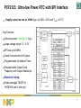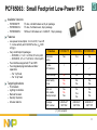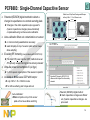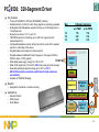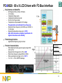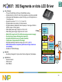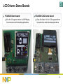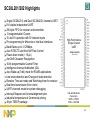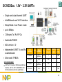
1
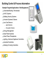
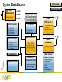
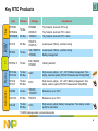
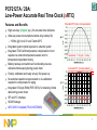
Building Control & Process Automation BL-IP, BU-HPMS 2Q 2013 v1.0 1 Building Control & Process Automation Example Targeted Applications / End Equipments Automated Building Thermostats HVAC Systems Building Security Systems Intrusion Systems & Alarms Low Cost Sensors – Leak Detectors – Occupation Sensors Energy Management Solar Panel Systems Smart Power Receptacles Lighting, Audio and Appliance Controllers Industrial Controllers Heating & Cooling Controllers 2 NXP Solution System Block Diagram Power Management • TEA15xx (STARplug) Interface Product 3.3V 2.5V 1.8V Radio (IEEE 802.15.4) GPIO Expander • • • • 4-Bit Expanders 8-Bit Expanders 16-Bit Expanders 40-Bit Expanders Real Time Clock • Accurate RTC with SPI & I2C Interface • Low Power RTC with SPI or I2C Interface LCD Driver • Segment Driver • Character Driver • Dot Matrix Driver • Single-Channel • Dual-Channel • Eight-Channel Home Area Network (HAN) Microcontroller • • • • • • LPC1100 (M0; 50MHz) LPC1200 (M0; 33MHz) LPC1300 (M3; 72MHz) LPC1700 (M3; 100MHz) LPC1800 (M3; 150MHz) LPC4300 (M4; 150MHz) Temp. Sensor Capacitive Sensor • JN5148 (128KByte RAM; Low Power) • Modules Available Bus Buffer / Voltage Translator • Long Distance Bus Buffers • Active Level Shifters • Passive Level Shifters Radio (ISM Band) • RF Discrete / Small Signals Wide Area Network (WAN) Other Relevant Interface Products • • • • • • Power Line Modem LED Controller Stepper Motor Controller UART Bridges Muxes & Switches 3 Real Time Clocks 4 Standalone RTC Highlights RTC Families: • • • • • Lowest Power RTC Family Low Cost, Low Power RTC Family Accurate RTC Family Automotive RTC Family Accurate/Automotive RTC Family PCF8523, PCF2123 PCF85063, PCF85063A, PCF85063B PCF2127(A)T/2, PCF2129(A)T/2 PCA8565, PCA21125 PCA2129T/Q900/2 Ultra-low power, I2C or SPI Interface Low power, I2C or SPI Interface Highly accurate RTC, I2C and SPI Interface High temp. up to 125°C, I2C or SPI Interface Highly accurate and AEC-Q100 compliant RTC 32kHz Quartz Key Features: • • • • • • • Time keeping Low power; <100nA ICC (PCF2123) Large voltage range; 1.5V to 5.5V Clock from seconds to 99 years Programmable Timer Frequency output Small packages (TSSOP8, HVSON10, etc) Oscillator/ prescaler CLKOUT POR Counters: s, min, h, day, month, year Supply Data I/O Interface I2C or SPI-bus 0, 1, …, 32768Hz Timer- Registers every second or every minute or timer Interrupt Value Proposition: • For highly accurate time-keeping, choose NXP RTCs with as low as ±3ppm accuracy • For long battery life, chose NXP RTCs with the industry’s lowest current consumption of less than 100nA • For rugged environment applications, there is no way around NXP RTCs with extended temperature range up to 125°C and AEC-Q100 automotive compliant qualification 5 Key RTC Products Automotive Precise !! Lowest Power Tiny Type Interface Package Key features PCF85063 PCF85063A I2C-Bus HWSON8 HXSON10 Tiny Footprint, best cost, RTC only Tiny Footprint, best cost, RTC + Alarm PCF85063B SPI Bus HXSON10 Tiny Footprint, best cost, RTC + Alarm PCF2123 SPI Bus TSSOP14, HVQFN16 Lowest power (100nA), electronic tuning PCF8523 I2C-Bus SO8, TSSOP14 HVSON8, Lowest power (100nA), electronic tuning Battery management PCF8563 /5 I2C-Bus SO8, TSSOP8, HVSON8 Industry standard PCF2129A, PCF2127A I2C-Bus/ SPI Bus SO20 High accuracy ±3ppm, -25°...+65°C Battery management, Time stamp, metal can quartz (PCF2127A features also 512byte RAM) PCF2129 PCF2127 I2C-Bus/ SPI Bus SO16 High accuracy ±3ppm, -40°..+85°C Battery management, Time stamp, ceramic quartz (PCF2127 features also 512byte RAM) PCA8565 I2C-Bus TSSOP8, HVSON10* Robustness: up to 125°C PCA21125 SPI Bus TSSOP14 Robustness: up to 125°C PCA2129 I2C-Bus/ SPI Bus SO16 High accuracy ±3ppm, Battery management, Time stamp, ceramic quartz for automotive * HVSON10 package variant is not automotive grade 6 PCF2127A / 29A: Low-Power Accurate Real Time Clock (aRTC) Standard RTC (Non-Compensated) Features and Benefits High accuracy (±3ppm; typ.) for accurate time reference Ultra-low power consumption enables long battery life f / fo – ~500nA @ VDD=2.0V and Tamb=25ºC Integrated quartz crystal requires no external quartz Integrated TCXO with temperature compensation circuit requires no external temperature sensor and no temperature dependent tuning Remember: 11.5 ppm = 1s/day. Battery backup and switchover functionality ensures reference timekeeping during power down Accurate RTC (Compensated) Factory calibrated and ready at very first power up No external capacitors required and no re-calibration required to compensate for aging f / fo Integrated 512-byte RAM (PCF2127A) for retaining critical data during power down SPI and I2C Interface SO20 Package Typical Error: Only ±3ppm over -15°C to 60°C AEC Q100 Compliant (PCA2129T/Q900) 7 PCF2127(A) / 29(A): Differences in Accuracy Key features: The PCx2129 comprises a Real Time Clock (RTC) and a temperature compensated quartz oscillator (TCXO). The quartz crystal itself is integrated into the package. There are 2 major version one in SO20, the other one in SO16. They feature different frequency response. Type number PCF2127AT, 2129AT PC2127T/2, 2129T Industrial Industrial General Quality spec GQS General Quality spec GQS Frequency accuracy +/- 5ppm -15°C…+60°C +/-10ppm -25..-15, 60..65°C +/- 8ppm -30°C…+80°C +/-15ppm <-30°C, >80°C Construction Metal can quartz Ceramic quartz TSMC Taiwan APB Bangkok Thailand APB Bangkok Thailand TSMC Taiwan APB Bangkok Thailand APB Bangkok Thailand Released, mass production Release, mass production SO20 SO16 drop-in compliant to SO20 Version Grade Silicon foundry Assembly fab Wafer and final test Release status Package Quartz Type 8 PCF2123: Ultra-low Power RTC with SPI Interface Supply current as low as 100nA (typ.) at VDD = 2.0V and Tamb = 25 ºC Key Features: Ultra low power 100nA @ 2V (typ.) Large voltage range 1.5…5.5V SPI bus up to 6MHz Clock from seconds to 99 years Programmable Countdown Timer Programmable Output Clock Frequency with Output Enable pin Electronic tuning Small packages TSSOP14, HVQFN16 and U (die only) 9 PCF8523: Ultra-low Power RTC with I2C Interface Supply current as low as 150nA (typ.) at VDD = 3.0V and Tamb = 25 ºC Key Features: Standard mode Ultra low power 150nA @ 3V (typ.) Large voltage range 1.6…5.5V 1MHz Fast-mode Plus (Fm+) I2C Interface VDD VDD Clock from seconds to 99 years Programmable Countdown Timer Programmable output clock Power Fail Detection Function Battery Switch-Over Function Direct switching mode Battery Low Detection Function Electronic Tuning Packages: SO8, TSSOP14, HVSON8 & U 10 PCF85063: Small Footprint Low-Power RTC Available Versions: – PCF85063TP: – PCF85063ATL: – PCF85063BTL: I2C-bus, Limited feature set, 8-pin package I2C-bus, Full feature set, 8-pin package SPI-bus, Full feature set + CLKOUT, 10-pin package Features – Low-power consumption; At VDD=2.0V, TAMB=25 °C, no bus activity and CLKOUT active, IDD=260 nA (typ) – Very small footprint packages o HXSON8, 2.1 x 3.1 x 0.5mm; 0.5-mm pitch o HXSON10, 2.7 x 2.7 x 0.5mm; 0.5-mm pitch – Two interfaces supported; I2C and SPI – Two integrated programmable oscillator capacitors o For 7-pF load o For 12-pF load Electronic tuning Target Applications – – – – – Thermostats Lighting Controllers Remote Sensors Security Systems Intrusion Alarms Function PCF85063TP PCF85063ATL PCF85063BTL Yes Yes Yes I2C-bus SPI interface P P 1 min interrupt No Yes Yes Alarm facility Timer No No Yes Yes Yes Yes CLK out CLK enable Interrupt output Yes No Yes Yes Yes Yes Yes HXSON-8 [1] SOT1052 HXSON-8 [1] SOT1052 Package SOT number P Yes Yes HXSON-10 [1] SOT1197 [1] 0.5-mm pitch 11 Capacitive Sensor 12 Capacitive Sensors Value Proposition Why used? – – – – No contact required (no actual pressing on touch area) Works even when wearing gloves Works in dirty environment (self-calibrating) Works together with any event that generates a predefined change in capacitance Where used? – – – – Switches for use in building lighting, fans, blinds, etc. Switches in medical and industrial environment Sanitary applications like in public rest rooms Proximity detection (tamper-proof ) in embedded equipment Why NXP? – Products are very sensitive, highly configurable and consumes low power 13 Capacitive Sensor Portfolio Single Channel PCF8883 • One input one output • Does not require a microcontroller • Available in two packages • PCF8883T (SOIC8) • PCF8883US (WLCSP8) Dual Channel PCA8886 • Two inputs, two outputs • Does not require a microcontroller • May be used for up to 3 sensors • AEC-Q100 compliant • Available in TSSOP16 (PCA8886TS/Q900/1) Eight Channel PCA8885 and PCF8885 • 8-Channels • Requires a microcontroller • May be configured for up to 28 sensors • With two devices, user may enable up to 80 sensors • Available as both industrial and automotive versions in TSSOP28 • Industrial version also available in SOIC28 package. MLF 28-pin package under consideration. 14 PCF8883: Single-Channel Proximity/Touch Switch Touch Sensor PCF8883 Self calibrating touch switch, SO8 Touch/Proximity Switch for User Interface – – – – – – Replacement of mechanical switches No need for mechanical opening or cleaning surface Hygienic aspect Auto (self) calibrating disregards contamination No wear out of contact Single channel device Superior Device Specification – Digital processing method – Open-drain output (P-type MOSFET, external load between pin and GND) – Output configurable as push-button, toggle or switch – Low-power battery operation possible (IDD < 5mA) – Extended battery-voltage operating range (2.8V < VDD < 9V) – Adjustable response time and sensitivity – Patented algorithm which offers best performance 15 PCF8883: Single-Channel Capacitive Sensor Wafer-Level Chip-Scale Package with Bumps: only 0.86 x 1.16 x 0.64mm in size Patented (EDISEN) digital method to detect a change in capacitance on a remote sensing plate. 0.53mm 0.86mm Changes in the static capacitance (as opposed to dynamic capacitance changes) are automatically compensated using continuous auto-calibration. Auto-calibration filters out contamination on sensor 1.16mm 0.64mm 0.64mm no microcontroller recalibrations necessary water droplets on top of a sensor plate will not cause false switching Excellent RF Immunity (in accordance with IEC62132-4) The direct RF power injection (DPI) method shows an RF immunity several-fold higher than industry standard Ultra-low power consumption of 3mA (typ.) ¼ of the power consumption of the nearest competitor Available in Wafer-Level-CSP with bumps: only 0.86 x 1.16 x 0.64mm in size Excellent RF Immunity (IEC62132-4): several-fold higher than the industry standard for reflow soldering and in tape and reel Auto-calibration: Water droplets on top of the sensor plate will not cause false switching Patented (EDISEN) digital method: static capacitance changes are filtered out; dynamic capacitance changes are processed 16 PCF8883: Evaluation Kit (OM11055) Allows tuning of external components Inclusion of op-amp allows measuring the voltage on CCPC without disturbing the loop Several sensor plate sizes to evaluate Power supply via USB or battery (USB cable included) Support documents: – – – PCF8883 – Capacitive Proximity Switch with Auto-Calibration UM10370: User Manual for the PCF8883 Evaluation Kit OM11055 Datasheets: PCF8883, PCA8886 AN10832: Reconfigurable TYPE Input to support pushbutton, toggle and pulse output signals T R T R Push-Button Toggle Pulse tP tP 17 PCA8886: Dual-Channel Proximity/Touch Switch Touch Sensor PCA8886 Self calibrating touch switch, TSSOP16 Features – – – – – – – – – – Dynamic proximity switch Adjustable sensitivity Adjustable response time Wide input capacitance range (10pF to 60pF) Automatic calibration Large distance (several meters) between sensing plate and IC is possible Low power consumption (IDD = 6mA) Open-drain output configurable as push-button, toggle, or pulse Extended battery-voltage operating range (3V < VDD < 9V) Patented algorithm which offers best performance 18 PCA8886: Application Board (OM11052) Detects proximity and touch Demonstrates door handle activation with proximity sensing Proofs high immunity to environmental changes with measurements performed from -40 °C to +85 °C – – Operates even with build-up ice on the door handle in the chamber at -40 °C. Operates even with mixture of condensation and ice on the door handle when moved to room conditions. Two touch areas are active – – Touch sensor with small area on the top side Proximity sensor with large area on the bottom side Support document: – UM10711: Slim Proximity Touch Sensor Demo Board OM11052 19 F PCA8885: 4x4 Channel Capacitive Sensor CPC2 Key Features: – – – – – – Based on the PCF8883 algorithm I2C-bus interface Adjustable scanning frequency Channel masking feature Fast start-up mode One sub-address enables 2 devices per bus – Sleep mode, activated via I2C bus or external input – Three sensing modes; one key, two keys and N-keys – Two events handling modes; direct and latching modes Benefits: Sensor logic CPC8 CLIN8 OSC Interrupt Sense register Supply I2C-bus interface Contact plates LCD Display VSS VDD SCL SDA SA0 INT – Address pin enables cascading of two devices and achieving up to 80 keys Applications: – Switchless keypads 20 PCF8885: Single Device with up to 28 Sensors Sensors 1 to 28 are each connected to two channels Sensor 1 is connected to CH1 & CH2 Sensor 2 is connected to CH1 & CH3 Device should be used in the 2-key mode After reading the SENS register, from the two bits set, the user can infer which sensor is touched. Sensor 8 is connected to CH2 & CH3 Total of 28 Sensors 21 F PCA8885: Cascading Application Device Configuration: – With Device#1, A0=VDD; With Device #2, A0=GND – Address pin enables cascading of two devices and connecting 80 sensors as follows: o 64 sensors in a 8x8 matrix o 8 sensors to Device#1 o 8 sensors to Device#2 – User can determine which sensor is triggered Device#1 o If both /INT are asserted, one of the 64 sensors is triggered o If only one device’s /INT is asserted, then one of the 8 sensors connected only to the device is triggered. Device#2 22 PCF8885 / PCA8886: Evaluation Kit (OM11057) Demonstrates the use of a single PCF8885 device in a multiplexed mode to achieve up to 28 sensors (19 sensors used on the board) Implements four touch buttons, a wheel and a slider Operates the PCF8885 in the 2-key mode and use the 2 out-of 8 code to enable 19 different sensor locations (7 for the slider, 8 for the wheel and 4 buttons) Enables touch sensitivity through a 3-mm acrylic overlay plate Uses the PCA8886 device in a proximity sensor mode to wake up board only when in use and demonstrates power saving features Feedback with a piezoelectric sound buzzer Feedback with RGB LED’s Support documents: – – – – – UM10505: AN11122: OM11057 Quick Start Guide Water and Condensation Safe Touch Sensing with the NXP Capacitive Touch Sensor AN11155: General Design Guidelines for the NXP Capacitive Sensors AN11157: Capacitive Touch Sensing with High EMC Performance Datasheets: PCF8885, PCA8886, PCF8536 23 PCF8885 / PCA8886: Evaluation Kit (OM11057) The 2-out-8 code was exploited to enable 19 different combinations in the command area 7 for the slider, 8 for the wheel and 4 buttons 1 2 3 4 5 6 7 8 9 10 11 12 13 14 15 16 17 18 19 20 21 22 23 24 25 26 27 28 b7 0 0 0 0 0 0 1 0 0 0 0 0 1 0 0 0 0 1 0 0 0 1 0 0 1 0 1 1 b6 0 0 0 0 0 1 0 0 0 0 0 1 0 0 0 0 1 0 0 0 1 0 0 1 0 1 0 1 b5 0 0 0 0 1 0 0 0 0 0 1 0 0 0 0 1 0 0 0 1 0 0 1 0 0 1 1 0 Inputs b4 b3 0 0 0 0 0 1 1 0 0 0 0 0 0 0 0 0 0 1 1 0 0 0 0 0 0 0 0 1 1 0 0 0 0 0 0 0 1 1 0 1 0 1 0 1 1 0 1 0 1 0 0 0 0 0 0 0 b2 0 1 0 0 0 0 0 1 0 0 0 0 0 1 1 1 1 1 0 0 0 0 0 0 0 0 0 0 b1 1 0 0 0 0 0 0 1 1 1 1 1 1 0 0 0 0 0 0 0 0 0 0 0 0 0 0 0 b0 1 1 1 1 1 1 1 0 0 0 0 0 0 0 0 0 0 0 0 0 0 0 0 0 0 0 0 0 24 PCF8885: Plug-In Daughter Card (OM11057A) Multi-channel capacitive sensor plug-in board with two PCF8885 and one PCA9535 devices – – – One PCF8885 device used for touch buttons One PCF8885 device used for slider PCA9535 device used to drive LED’s Board plugs into Evaluation kit (OM11057) Enables touch sensitivity through a 10-mm thick polycarbonate panel, acrylic overlay plate, or another insulating material Connector allows access to VDD, GND, I2C signals, and interrupt to enable system development and evaluation 25 PCx8885: Evaluation Board (OM11056) PCF8885 or PCA8885 evaluation board with two TSSOP 28-pin sockets Can be directly connected to the I2C-bus and attached to the sensor plates in the customer’s application Support document: – UM10664: PCA8885 and PCF8885 Evaluation Board OM11056 Custom Sensing Board PCx8885 Evaluation Board 8-Line Flat Cable I2C-bus USB to I2C-Bus Translator 26 PCF8885: Touch Panel Demonstrator (OM11058) Key Features: 7-Inches Capacitive Touch Panel from Dytos glued on top of a standard TFT display Two PCF8885 devices connected to a touch foil to detect 64 sensor areas (16 of 64 sensors are used in this demo) LPC1768 and emWIN used to generate Graphics and GUI Prototype available now 27 LCD Drivers 28 LCD Driver Value Proposition Where used? – – – – Thermostats / HVAC Intrusion & Building Security Systems Lighting Remote Controls Energy Meters & Energy Management Controllers Segment Drivers’ Key Features – – – – – Low power & driving up to 640 segments Standalone – no need for external components I2C and SPI interfaces available AEC-Q100 options Cascadable Character Drivers’ Key Features – Combines low power segment display with sophisticated 2-line character display – Integrated generation of VLCD with temperature compensation – Very low power consumption (20 to 200mA) – Display shift or static display modes Graphic Drivers’ Key Features – On-chip generation of LCD bias voltages – Low number of external components – Low power consumption 29 LCD Drivers: Differentiations Segment Drivers Character Drivers Graphic (Dot Matrix) Drivers Features: Features: Features: • • • • • • • • Multiplex rate up to 1:18 • On-chip character generator • 5x7 character + cursor; 5x8 for Kana (Japanese) & user-defined symbols • On-chip temperature compensation • On-chip character ROM and RAM • Low power consumption • Minimum external components • On-chip LCD bias voltage generation • Internal oscillator / external clock • Wide range of mux rates to optimize power and display size (S/W selectable) • On-chip generation of LCD bias voltages • Low number of external components • Low power consumption • Temperature compensation Max multiplex rate 1:16 (generally 1:4) Wide range of segment outputs RAM and auto-incremental addressing Low power consumption No external component Wide power supply range Internal LCD bias voltage generation with voltage follower buffers • Internal oscillator, external clock also possible 30 LCD Drivers: Key Products Segment Drivers • PCF8566 • PCA F 85162 A • PCF 85176 • PCF85134 • PCA F 85133 • PCA F 85132 A • PCF 8536 A • PCF 8537 4 x 24 Segments • PCA9620 8 x 60 Segments Character Drivers • PCF2113 2-Line x 12-Character Plus 120 icons • PCF2116 4 x 32 Segments 4 x 40 Segments 4 x 60 Segments Graphic (Dot Matrix) Drivers • PCF8531 34 x 128 Small 4-x-20 Text Characters Full Graphics 4-Line x 12-Character or 2-Line x 24-Character • PCF8811 80 x 128 Large Universal Display 2-Line x 16-Character Plus160 icons • PCF8578 8 x 32 (stand-alone) Up to 40,960 dots when combined with 32 PCF8579 4 x 80 Segments 4 x 160 Segments 8 x 40 Segs + 6PWM • PCF2119 8 x 44 Segments For Details, see the LCD Drivers Selection Guide 31 PCAF8536: 320-Segment Driver Key Features: – I2C-bus (PCx8536AT) or SPI-bus (PCx8536BT) interface Mux # Display Segments – Interfaces directly to the LCD cells; driving signals are internally generated – 40-Segment and 8-Backplane outputs for driving up to 320 Segments in a w/o PWM w/ 6x PWM 1:8 multiplex rate 1:4 176 152 – Supports mux rates of 1:4, 1:6, and 1:8 1:6 252 216 – 7-Bit PWM outputs for controlling up to 6 LED’s in conjunction with 1:8 320 272 external transistors – Configurable backplane outputs; either pinout in the centre of the segment outputs or at the edge of the device – Programmable Line Inversion or Frame Inversion PCx8536 TSSOP56 – Programmable and calibrated Frame Frequency in the range of 60Hz to 300Hz in steps of 10Hz (typical) control I2C/SPI Bus – Wide digital power supply range from 1.8V to 5.5V logic – Wide VLCD range from 2.5V to 6.5V (9.0V) when using an external supply – Extended operating temperature range up to +85 ˚C (+95 ˚C) – AEC-Q100 automotive compliant qualification for high robustness RAM and reliability – Available in TSSOP56 Package Benefits: – Designed for horizontal or vertical mounting sequencer backplane driver 8 Applications: – Industrial Control – White Goods – Smart Meters bias voltage generator PWM Controller segment driver 40 32 PCA9620: 60 x 8 LCD Driver with I2C-Bus Interface Key features and benefits – – – – – – – – – – 480 Segment Drive in Mux 1:8 Mode I2C Interface Integrated charge pump Integrated temperature sensor On-chip VLCD generation Temperature compensated VLCD voltage Programmable and calibrated frame frequency Extended frame frequency from 60Hz up to 300Hz; in 10-Hz steps Extended temperature range up to +105°C AEC-Q100 automotive compliant qualification for highest robustness and reliability Potential applications – Applications Requiring High Contrast Product characteristics – – – – – Wide digital and analog power supply ranges from 2.5V to 5.5V Extended VLCD range from 2.5V to 9.0V Wide frame frequency range 60Hz to 300Hz Wide operating temp range -40 to +105°C 12 x 12 x 1.4 mm LQFP80 package Black Nematic: VLCD=7.0V, fF=200Hz Twisted Nematic: VLCD=7.0V, fF=100Hz Business Line Interface Products - Product Line CWG 33 F PC A8537: 352 Segments or dots LCD Driver Key Features: – I2C-bus (PCx8537AH) or SPI-bus (PCx8537BH) interface – Interfaces directly to the LCD cells; driving signals are internally generated – 44-Segment and 8-Backplane outputs for driving up to 352 Segments in a 1:8 multiplex rate – Supports mux rates of 1:1, 1:2, 1:4, 1:6, and 1:8 – Programmable Line Inversion or Frame Inversion – Programmable and calibrated Frame Frequency in the range of 60Hz to 300Hz in steps of 10Hz (typical) – Wide digital power supply range from 1.8V to 5.5V I2C Bus – Wide analog power supply range from 2.5V to 5.5V – Wide VLCD range from 2.5V to 9.0V when using an external supply – On-chip charge pump with integrated capacitors – Integrated temperature sensor (readout possible) – Temperature compensated VLCD voltage – Extended operating temperature range up to +85 ˚C (+95 ˚C) – AEC-Q100 automotive compliant qualification for high robustness and reliability – Available in TQFP64 Package Benefits: PCA8537 TQFP64 control logic RAM Temp Sensor sequencer backplane driver 8 bias voltage generator – Specifically Designed for high-contrast Vertical Alignment (VA) displays Applications: – Industrial Control – White Goods – Smart Meters Charge pump segment driver 44 34 LCD Drivers Demo Boards PCA9620 Demo board: 60 x 8 LCD segment driver in LQFP80 pkg for automotive and industrial applications PCA8538 COG Demo board: Chip-On-Glass 102 x 9 LCD segment driver for automotive and industrial applications 35 Segment Display Touch Panel Demonstrator Key Features: Stand-alone demonstration kit showcases NXP’s Capacitive Sensor Technology Segment display is driven by one PCF85176 (4x40) Segment Driver Polarizer ITO Touch Layer + Glass ITO Layer (Electrode) Touches are detected by one PCF8885 (8-CH) Capacitive Sensor High-contrast is attained with vertical alignment (VA) display with 16 touch buttons on-cell 36 Bus Buffers & Voltage Translators 37 I2C-Bus Buffer Family Repeaters PCA9509 Processor to SMBus PCA9509A Processor to SMBus PCA9509P Processor to SMBus PCA9517A 0.9 – to 5.5V PCA9507 RTA for HDMI PCA9527 PCA9507 + ½ PCA9517 PCA9617A 0.8 to 5.5V SO SO SO SO SO SO SO Extenders (Long Cable) Hot-Swap Buffers PCA9515/15A/16A SO PCA9518A 5-Channel Hub Expander PCA9519 4 x PCA9509 PCA9525 3-mA Drive PCA9605 30-mA Drive PCA9646 30-mA Drive; 1:4-Channel SO SO NO NO NO PCA9521 [1] PCA9522 wo/HS [1] Devices in development [2] PCA9522 is compliant for ATCA applications [3] P82B96 is widely used for opto-isolation applications Blue 1 MHz system IO (Long Cable Drivers) PCA9522[2] IO PCA9508 SO Active Level Shifter PCA9512A/12B Active Level Shifter PCA9511A 0.6-V Threshold PCA9514A 0.8-V Threshold PCA9513A 92-mA Current Source PCA9510A No Accelerator IO P82B96 [3] SO P82B715 AM No Static Offset PCA9600/9601 1-MHz Speed SO IO IO IO NO = No Offset IO SO = Static Offset IO = Incremental Offset AM = Amplifier 38 Static-Offset Bus Repeater Value Proposition Why used? – Voltage level shifting between host processor’s I2C-bus and peripheral devices when there is a mismatch of supply voltages – Used when additional drive is needed or to isolate two sections of the bus loading Where used? – Digital logic level translation between host processor and slave device where capacitance isolation and speed of >3MHz (up to 30MHz) is required NXP Level Shifter Portfolio Device Description Normal I/O Static Level Offset I/O Accelerator Idle Stop Detect for Hotswap Interrupt ESD (HBM) PCA9508 0.9V-to-5.5V Level Shifter with Offset Free Hot-Swap A Side B Side PCA9509 1.0V-to-5.5V Level Shifter B Side A Side 2KV PCA9515A 3.3V / 5.0V I2C-Bus Repeater A & B Sides 2KV PCA9516A 5-Channel I2C Bus Hub A & B Sides 2KV PCA9517A 0.9V-to-5.5V Level Shifter A Side B Side 5KV PCA9617 0.8V-to-5.5V Level Shifter A Side B Side 5KV PCA9518A 5-Channel I2C Bus Hub Expander A & B Sides 2KV PCA9519 1.1V-to-5.5V Quad Level Shifter A Side 2KV B Side × 6KV 39 PCA9525, PCA9605 & PCA9646: No Offset I2C-Bus Buffer Features Extends bus load limit by buffering both SCL & SDA lines Uses a “scoreboard” technique to determine direction “Regenerating” and bi-directional SDA buffers “Regenerating”, but uni-directional SCL buffers Imposes minimal system design restrictions Ability to drive large buses and long cables Does not support clock stretching Differences: – PCA9525 supports 1MHz I2C Fast-mode (3 mA) and SMBus (4 mA) – PCA9605 supports Fast-mode Plus (30 mA) – PCA9646 supports Fast-mode Plus (30mA) and may be used to fan-out the bus (1:4 channels) Applications Re-driving of the I2C-bus with standard logic levels Regenerating standard logic levels on the bus 40 PCA9605: Fm+ I2C No Offset Bus-Buffer 30mA 30 mA FEATURES Bi-directional data transfer with unidirectional clock (direction pin) Scoreboard method provides for normal voltage levels on both sides of the device 30 mA sink capability for interfacing between Fm+ bus master and slaves PCA9605 Voltage Range 2.7V - 5.5V Fm+ Master Fm+ Slaves 1 MHz I2C-bus KEY POINTS Longer point-to-point or multi-point architectures Isolates capacitance allowing 4000 pF on both sides of the bus (540 pF @ 1 MHz) Normal interface works with any other device Temp. Range -40 ˚C to +85 ˚C Bus Voltage Range 2.7V - 5.5 V 41 Incremental I2C-Bus Buffers PCA9521 & PCA9522 Features “Regenerating” bi-directional SDA and SCL buffers with 1.8 – 10V bus range (device supply 2.7 – 5.5V) that can be used in series Impose minimal system design restrictions No rise time accelerators which might cause glitch Supports 1MHz I2C Fast-mode (6mA) Applications Multiple bus buffers needed for capacitance isolation and to buffer the I2C signals from board to board with connectors. Voltage level translation between a 1.8V or 2.5V bus and a 3.3V or 5V bus. When the system is fully loaded, some of the buffers are connected in series and the architecture is such that static offset bus buffers can’t be used The clock signal has to be bidirectional, so no offset bus buffers can’t be used. 42 Long-Distance Bus Buffers Value Proposition Why used? – Drives the I2C-bus signals over a long-distance cable and through inter-connects – Re-drive the SCL and SDA signals into loads exceeding the maximum specified 400-pF bus capacitance Where used? – – – – Between card interconnects (does not support voltage level translation) In noisy environment with compressors, pumps, relays, EMI, etc. To eliminate the need for multiple costly bus controllers Opto-Couplers Interface Why NXP Long-Distance Buffers? – Large selection of buffers – Continuous innovation with new differential I2C buffers (P82B48x) for very rugged environments – Invented the I2C-bus NXP Long-Distance I2C-Bus Buffer Portfolio Device VCC FMAX Max CableSide Load Cable Length P82B715 3.0V – 12.5V 100kHz 3,000pF 50m P82B96 2.0V – 15.0V 400kHz 4,000pF 20m PCA9600/01 2.5V – 15.0V 1MHz 4,000pF 20m PCA9605 2.7V – 5.5V 1MHz Capacitance Isolation Interrupt Signal Levels ESD (HBM) Single-ended 2.5KV × Single-ended 3.5KV × Single-ended 4.5KV × Single-ended 2.5KV [1] In Development 43 P82B715: I2C-Bus Extender Features Wide supply voltage range from 3V to 12V Amplifies the bus drive current in one direction Scales the current drive by 10x, but does not isolate the bus Scales the capacitive loading and is capable of driving 4000pF load Inputs have no switching level thresholds Compatible with I2C-bus, SMBus, and PMBus Does not do voltage level shifting Applications Driving a bus with low pull-up resistors Extending the communication distance of the I2C-bus over wire 44 Voltage-Level Translator Family Active Level Shifter - input & Output dual supply - Capacitance Isolation - High Noise Margins PCA9509/A/P Processor to SMBus PCA9507 RTA for HDMI PCA9517A 0.9 – to 5.5V PCA9527 PCA9507 + ½ PCA9517 PCA9508 Active Level Shifter SO SO SO SO SO Active level Shifter - Single Supply - Capacitance Isolation P82B96 2.2 – 15V PCA9518A 2.3 – 5.5V PCA9600/9601 2.2 – 15V PCA9306 SO 1 – 5.5V NO AM GTL2002/03/10/00 NO 1 – 5.5V SO NVT20xx NO 1 – 5.5V w low Ron PCA9515/15A/16A SO 2.3 – 5.5V Passive Level Shifter - No capacitance Isolation - Low Power & Low Cost NO = No Offset SO = Static Offset IO = Incremental Offset AM = Amplifier PCA9512A/12B Active Level Shifter PCA9519 4 x PCA9509 PCA9617A 0.8 to 5.5V IO Blue 1 MHz system SO SO 45 Active Level-Shifter Value Proposition Why used? – Voltage level shifting between host processor’s I2C-bus and peripheral devices when there is a mismatch of supply voltages – Used when additional drive is needed or to isolate two sections of the bus loading Where used? – Digital logic level translation between host processor and slave device where capacitance isolation and speed of >3MHz (up to 30MHz) is required Why NXP Level-Shifter? – Largest selection of active and passive level shifters – Continuous innovation with new NXP voltage follower and zero-offset active buffers NXP Level Shifter Portfolio Device Description Normal I/O Static Level Offset I/O Accelerator Idle Stop Detect for Hotswap Interrupt ESD (HBM) PCA9508 0.9V-to-5.5V Level Shifter with Offset Free Hot-Swap A Side B Side PCA9509 1.0V-to-5.5V Level Shifter B Side A Side 2KV PCA9515A 3.3V / 5.0V I2C-Bus Repeater A & B Sides 2KV PCA9516A 5-Channel I2C Bus Hub A & B Sides 2KV PCA9517A 0.9V-to-5.5V Level Shifter A Side B Side 5KV PCA9617 0.8V-to-5.5V Level Shifter A Side B Side 5KV PCA9518A 5-Channel I2C Bus Hub Expander A & B Sides 2KV PCA9519 1.1V-to-5.5V Quad Level Shifter B Side A Side 2KV PCA9527 3.0V-to-5.5V Level Shifter A Side B Side × × (A-Side) 6KV × 8KV 46 Passive Level-Shifter Value Proposition Why used? – Voltage level shifting between host processor’s I2C-bus peripheral devices when there is a mismatch of supply voltages – Used when additional drive is not needed and capacitive loading is not an issue Where used? – Digital logic level translation between host processor and slave device; no direction control, speed of <3MHz and no capacitance isolation are required – Applications requiring open-drain bidirectional or unidirectional voltage translation (down to 1V) without a direction pin Why NXP Passive Level-Shifter? – Largest selection of active and passive level shifters – Continuous innovation with new NXP Voltage Translation family (NVT20xx) in widths of 1, 2, 3, 4, 6, 8 and 10 bits NXP Passive Level-Shifter Portfolio Device Description RON Process ESD (HBM) PCA9306 2-Bit Bidirectional Voltage-Level Translator 3.5 W CMOS 2kV GTL2002 2-Bit Bidirectional Voltage-Level Translator 6.5 W BiCMOS >2kV GTL2003 8-Bit Bidirectional Voltage-Level Translator 6.5 W BiCMOS >2kV GTL2010 10-Bit Bidirectional Voltage-Level Translator 6.5 W BiCMOS >2kV GTL2000 22-Bit Bidirectional Voltage-Level Translator 6.5 W BiCMOS >2kV NVT2001/02/03/04/ 06/08/10 x-Bit Bidirectional Voltage-Level Translator 3.5 W BiCMOS >4kV 47 PCA9306 Bidirectional I2C-Bus & SMBus Level Translator Features Bi-directional without need for direction pin Voltage translation between any voltage from 1.0 V to 5.5 V Lock-up free operation for isolation when EN = LOW Mixed-mode I2C-bus application: run two buses, one at 400 kHz other at 100 kHz operating frequency Excellent ESD performance 3.3 V 3.3 V 1.2 V GND VREF1 RPU PCA9306 1.5 V RPU 200K 1.8 V RPU Voltage Level Translation – Mixed-mode I2C-Bus Applications 2.5 V RPU Applications EN VREF2 VCC VCC I2C SCL SCL1 SCL2 SCL BUS MASTER GND I2C BUS DEVICE SDA SDA1 SDA2 SDA GND 48 NVT20xx: Level Translator Family Where used? – Digital Logic level translation – TI’s PCA9306 is drop-in replacement for NXP GTL2002 and PCA9306 Why used? – Voltage level shifting in range of 1V and 5V – Bi-directional without direction pin Why NXP NVT 20xx Level Shifter? – More consistent device naming - NVT means “NXP Voltage Translator” o NVT2001 – 1-bit o NVT2002 – 2-bit (alt source GTL2002) o NVT2003 - 3-bit o NVT2004 – 4-bit o NVT2006 – 6-bit o NVT2008 – 8-bit (alt source GTL2003) o NVT2010 – 10-bit (alt source GTL2010) – In TSSOP and smaller packages – Can be used as FET replacement – Continuous innovation from NXP # CH New OLD Usage 1 NVT2001 -- Clock 2 NVT2002 PCA9306 GTL2002 I 2C 3 NVT2003* -- I2C, server 4 NVT2004* -- SPI 6 NVT2006 -- 8 NVT2008 GTL2003 Digital RGB 10 NVT2010 GTL2010 Data Bus 22 -- GTL2000 * sampling 49 General Purpose I/O Expanders 50 GPIO Expander Value Proposition Why used? – Easily adds I/O via I2C-bus – Additional inputs for keypad, switch, signal monitoring and fan control – Additional outputs for LED control, ACPI power switch, relay, timers and sensor. Microcontroller Where used? – HVAC Controllers – Building Intrusion Systems – Industrial Controls – Energy Management Systems – Test and Measurement Instrumentations Why NXP GPIOs? – Largest selection of 4, 8, 16 and 40-bit GPIO in Quasi-bidirectional and Push-pull outputs with Interrupt and/or reset in a wide range of packages – Invented the I2C-bus. Continuously developing newer devices with added features to support different applications. Keypad Control 2-wire GPIO GPIO Zoom-in view 51 I/O Expanders with Flexible Output Structures Quasi-Output Structure: - Strong PMOS transistor is turned on only during the LH transition and turned off during static drive - Weak pull-up current source (100μA) at the output - Used in low-power applications where the 100-μA drive is sufficient to bias the inputs of CMOS devices - May be reconfigured as an input or output without the need of a port configuration register Totem-Pole Output Structure: - Upper PMOS transistor is turned on during LH transition and static high drive. Up to 10mA (or 25mA) of high drive - Some devices have weak pull-up resistors at the output - Used in applications requiring high drive for heavy loads - Extra command byte needed to switch an I/O pin between input and output 52 Quasi-Output I2C I/O Expanders Device Number of I/O’s Features RESET INTERUPT EEPROM I/O Pull-Up [1] PCF8574(A) 8 × Weak PU PCA8574(A) 8 × Weak PU PCA9500 8 PCA9501 8 PCA9558 [2] 8 PCA9670 8 × PCA9672 8 × PCA9674 (A) × 2 Kbit Weak PU 2 Kbit Weak PU 2 Kbit Weak PU Weak PU × Weak PU 8 × Weak PU PCF8575 16 × Weak PU PCF8575C 16 × Open Drain PCA8575 16 × Weak PU PCA9671 16 × PCA9673 16 × PCA9675 16 Note [1]: Note [2]: Weak PU × Weak PU × Weak PU The Quasi-outputs have a strong pull-up (transistor) to VDD to allow fast rising edges into heavy loaded outputs. The devices with weak pull-ups have a 100-mA current source to VDD. With 5-Bit Mux, 1-Bit Latch Dip Switch 53 Totem-Pole Output I/O Expanders Device Number of I/O’s Features RESET INTERUPT Other PCA9536 4 PCA9537 4 × × PCA9502 8 × × PCA9534 8 PCA9538 8 PCA9554 (A) 8 PCA9557 8 × PCA9574 8 × PCA9535 16 × PCA9535C 16 × PCA9539 (R) 16 PCA9555 16 PCA9575 16 × Maskable PCA9505 40 × × PCA9506 40 × × OE PCA9698 40 × × OD or PP, OE I/O Pull-Up 100KW SPI + I2C × × × × × 100KW 100KW Maskable OD or PP, LV Prog. PU / PD Open Drain × × 100KW OD or PP, LV Prog. PU / PD 100KW 54 Open-Drain Output I2C I/O Expanders Devices – The PCF8575C and PCA9535C are 16-bit GPIO Expanders with open drain outputs. – Some push-pull GPIO Expanders’ outputs can be configured to turn off the upper PMOS transistor and used as open-drain devices – The PCA9574 is an 8-bit GPIO Expander – The PCA9575 is a 16-bit GPIO Expander – The PCA9698 is a 40-bit GPIO Expander Features PCF8575C Output Structure PCA9535C Output Structure Strong PMOS on for ½ SCL VCC I/O 100 uA Output input ~25 mA ~25 mA – The PCF8575C has a strong PMOS pull-up transistor to pull the signal from low to high, when the device is driving as an output. – The PCA9535C has true open-drain output structure. – Both devices have open-drain interrupt output. Applications • Strong PMOS transistor is turned on only during the LH transition – The open-drain output GPIO Expanders are suited for applications requiring the expanders • PMOS transistor is off during to put the I/O in high-impedance state and static drive safe in power consumption. • No upper PMOS transistor • No pull-up resistor • No weak current drive 55 GPIO Expanders Applications: PCA9698 Example I2C-bus Serial Interface – Fast-mode Plus (1MHz) – Supports up to 64 devices on same bus Control Inputs and Outputs – Reset – Interrupt (maskable) – OE Configurable Outputs – Push-pulls – Open-drain Wide Applications – Driving individual LEDs – Driving LED matrix – Reading from Keypad – Subsystem control signals – Subsystem status signals – Live Insertion (IOFF) Supports 56 Low-Voltage GPIO Expanders Features: Operates from 1.65V to 5.5V; designated by “A” at the end of the part number, e.g. PCA9555A Drop-in replacement for previous GPIO Expanders which operates from 2.3V to 5.5V Input latch and other new Agile I/O features, designated by “L” in the middle of the part number, e.g. PCAL9555A Agile I/O provides the following features: GPIO input latch (bit by bit – default not latched). Locks I/O pin change on input until the register is read. GPIO output drive strength control (bit by bit – default 10 mA). User can program I/O drive strength 2 mA, 4 mA, 8 mA or 10 mA. Could be used to control the brightness of LEDs. GPIO open drain control (24-bit bit by bit and 8 and 16-bit bank by bank – default push pull). Provides an optional open-drain output for each I/O pin. GPIO pull up or pull down (bit by bit – default no PU/PD). User can turn on/off an internal pull-up or pull-down on each I/O pin. GPIO interrupt mask and interrupt status (bit by bit – default not masked). User can enable or disable interrupts of each I/O pin. Identifies the source of interrupts of each I/O pin. 5 state address pins to allow more devices on the bus (24-Bit GPIO Expanders only) Dual supply voltages, designated by “64” in the part number, e.g. PCA6416A Single VCC INT & PU INT INT & RST Two VCC INT & PU INT INT & RST Input Latch Input Latch Input Latch INT & RST INT & RST Feature 8 bit PCA9554B PCA9554C 16 bit PCA9555A 24 bit PCA9535A PCA9538A PCAL9554B PCA9554C PCA9539A PCAL9555A PCAL9535A Input Latch PCAL9538A PCA6408A PCAL6408A PCAL9539A PCA6416A PCAL6416A PCA6424A PCAL6424A 57 Low-Voltage GPIO Expanders – Comparison Table Feature PCA9574/75 PCA64XX PCAL64XX Number of I/O’s 8 or 16 8 or 16 or 24 8 or 16 or 24 Serial Interface – 400 kHz I2C-Bus I2C-Bus I2C-Bus Comments 1, 2 or 16 2, 4 or 8 4, 5 or 8 One address pins provides two addresses except for the PCA9575 which has no address pins on the 24 pin version due to the separate supply per octal but the 28 pin version has four address pins allowing 16 devices on the bus. PCAL6424A have one pin with 5 input states. Supply Voltage Range at Vcc core and Vcc I/O 1.1 V to 3.6V 1.65 V to 5.5 V 1.65 V to 5.5 V Supports lower supply voltages with supply per octal for the PCA9574/75 and supply per total I/O for PCA(L)64XX. Input & Output, Polarity Inversion and Configuration Command Byte Yes Yes Yes Registers used by all I/O expanders to control/configure I/o pins Bus-Hold - Programmable Yes No No Very small current source maintains undriven line high or low, doesn’t cause continuous current drain when line is at opposite signal level. Pull-up / Pull-down - Programmable Yes No Yes 100-kΩ pull-up or pull-down at the I/O’s. Provides a valid logic level when the I/O is not actively driven. Input Latch - Programmable No No Yes Select which input changes “latch” in interrupt if input changes back before the register is read Interrupt Mask - Programmable Yes No Yes Select which input changes would not generate an interrupt to reduce spurious interrupts. Interrupt Status - Register Yes No Yes User may read this register to identify the source of an interrupt directly without having to remember the previous state of the input Open Drain Output - Programmable No No Yes Select I/O from push pull to open drain per byte (8 or 16-bit) or bit (24-bit) Output Drive Current - Programmable No No Yes Selects reduced portion of output to control slew rate Input Current Limiter No No Yes Reduces current through the input when input voltage is above the supply voltage Hardware Reset Yes Yes Yes External pin resets the state machine and I/O to default if fault Software Reset Yes No No User reset the device in software to quickly go to a know state 0.25 mA (Typ.) 1 mA (Max.) 0.1mA (Typ.) 2 mA (Max.) 0.1mA (Typ.) 2 mA (Max.) Number of devices on bus Istandby (VDD = 3.6V) Lower standby current (numbers shown are estimates for 24 bit LV GPIO, for 8 & 16 bit1.5uA (typ) 7uA (max) 58 PCAL6416A: Dual-VCC Low-Voltage, 16-Bit I2C-Bus Expander with /INT, Reset and Configuration Registers Features: Operating Power-Supply Voltage Range of 1.65 V to 5.5 V Low Standby Current Consumption of 3 µA (Max) Bidirectional Voltage-Level Translation between 1.8V to 5V SCL/SDA and 1.8V to 5V Totem Pole configured I/O Port Schmitt-Trigger Hysteresis; 10% of I2C-Bus Supply Voltage Fast Mode I2C-Bus Operating Frequency of up to 400-kHz Active-Low Reset Input Open-Drain Active-Low Interrupt Output 5-V Tolerant I/O Ports Output port configuration: bank selectable push-pull or open-drain output stages Interrupt status (read-only) register identifies interrupt source Bit-wise I/O programming for output drive strength, input latch, pullup/pull-down enable, pull-up/pull-down selection, and interrupt mask High current Drive for Directly Driving LEDs Internal Power-On Reset Power-Up With All Channels Configured as Inputs No Glitch On Power-Up Package – 24 pin TSSOP, HWQFN and CSP Latch-Up Performance Exceeds 100 mA per JESD 78, Class II ESD Protection Exceeds JESD 22 • • 2000-V Human-Body Model (A114-A) 1000-V Charged-Device Model (C101) 59 Temperature Sensors 60 Temperature Sensors Value Proposition Where used? – – – – – – Building Thermostats Energy Management Solar Panel Systems Power Receptacles Industrial Controllers Heating and Cooling Controllers Part # Accuracy SMBus Timeout LM75A / 75B ±2 ˚C A = No; B = Yes SE95 ±1 ˚C No SE98A ±1 ˚C Yes SE97B* ±1 ˚C Yes Why used? – Determine the temperature – Set window for Interrupt, alarm, fan control, shutdown, etc. local wire local Why NXP Thermal Sensor? – Large selection of commonly used local sensor and local/remote sensor thermal sensors in a wide range of packages – Continuous innovation with new low price LM75B local sensor in small 2 x 3 mm package Remote Diode Sensor Local Sensor Accuracy Remote Sensor Accuracy NE1617A ±2 ˚C ±3 ˚C SA56004 ±2 ˚C ±1 ˚C Part # Note: * With 2Kbit EEPROM 61 Thermal Sensor Portfolio ±1°C Remote, ±2°C Local, 11-bit ADC A c c u r a c y DDR3 SPD, ±1°C, 11-bit ADC, 2K EEPROM Low Voltage, ±1°C, 11-bit ADC SE95 SE98A SA56004 SE97B Improved ±1°C LM75, Local, 11-bit ADC ±3°C Remote, ±2°C Local, 8-bit ADC NE1617A LM75A PCT2075 ±2°C, 11-bit ADC LM75B Industry Standard, , ±2°C Local, 11-bit ADC Complexity Local only Remote & Local Samples Now In development 62 Thermal Sensor Selection Table Power Supply Voltage Range Supply Current Operating uA Supply Current Standby uA Package Option 0.125/11 2.8-5.5 1000 3.5 SO-8 TSSOP-8 0.125/11 2.8-5.5 300 1 SO-8 TSSOP-8 XSON-8 HWSON-8 ±3°C 1.0/8 3.0-5.5 70 3.0 QSOP-16 ±1°C 0.125/11 3.0-3.6 500 10 SO-8 TSSOP-8 ±1°C 0.125/11 3.0-3.6 400 3 HWSON-8 ±1°C 0.125/11 1.7-3.6 400 5 TSSOP-8 HWSON-8 1 SO-8 TSSOP-8 HWSON-8 TSOP6 1 NE1617A 1 1 ±2°C SA56004 1 1 ±2°C SE97B 1 SE98A 1 1 Temp Resolution / A/D Resolution Bits ±2°C LM75B PCT2075 Accuracy Remote (max) Accuracy Local (max) Local Channels 1 Remote Channels Part Number LM75A ±2°C ±2.0°C max, ±1.0°C typ 0.125/11 2.7-5.5 200 63 LM75B Local Digital Temp. Sensor & Thermal Watchdog Features Pin-for-pin replacement for industry standard LM75 and LM75A I2C-bus interface - 8 devices on the same bus Power supply range from 2.8 V to 5.5 V Temperatures range from -55 °C to +125 °C Frequency range 20 Hz to 400 kHz with bus fault time-out to prevent hanging up the bus 11-bit ADC - temperature resolution of 0.125 °C Temperature accuracy of: ±2 °C from -25 °C to +100 °C ±3 °C from -55 °C to +125 °C Programmable temperature threshold and hysteresis set points Max supply current of 1.0 µA in shutdown mode Stand-alone operation as thermostat at power-up ESD protection exceeds 4500 V HBM per JESD22A114, 450 V MM per JESD22-A115 and 2000 V CDM per JESD22-C101 Small 8-pin package types: SO8 and TSSOP8 64 PCTx075: I2C-bus Temperature Sensors FEATURES • • • • • • • • • Fm+ I2C-bus (1MHz) with SMBus timeout Power supply range - 2.7 V to 5.5 V Temperatures range - -55 °C to +125 °C Programmable temperature threshold and hysteresis set points allows customer-defined default Tos & Thyst set points Tidle programmable adjustment for temperature sampling. Allows reduction in power consumption Stand-alone operation as thermostat at power-up Expanded I2C address range with 3 state pins (27 @ 8pin and 3 @ 6-pin) address latched at power up 8-pin package types: SO8, MSOP8, HWSON8 6-pin package types: SOT23-6 (TSOP6) 11-bit ADC ± 2°C PCT2075 PCTabcd – Fm+ thermal sensor a = accuracy ± °C b = modifier to base device cd = base device PCT2075: 11-Bit ADC ±1 °C (max.) from −25 °C to +100 °C ±2 °C (max.) from −55 °C to +125 °C Package SO8 MSOP8 HWSON8 TSOP6 SOT23-6 SOT # SOT96-1 SOT505-1 SOT1069-2 SOT457 Pitch (mm) 1.27 0.65 0.5 0.95 Width (mm) 3.90 3.0 2.0 3.0 Length (mm) 3.90 5.0 3.0 1.5 Height (mm) 1.75 1.1 0.8 1.1 65 SA56004 Application Applications Energy Management Solar Panel System Building Controllers Heating and Cooling Controllers Industrial controllers and embedded systems Features On-chip local and remote microprocessor thermal diodes or diode connected transistors temperature sensing within ±1 °C Offset registers available for adjusting the remote temperature accuracy Programmable under/over temperature alarms: ALERT and T_CRIT SMBus 2.0 compatible interface, supports TIMEOUT and 100/400 kHz I2C interface 11-bit, 0.125 °C resolution 8 different device addresses are available for server applications. The SA56004-ED/EDH with marking code ARW is address compatible with the National LM86, the MAX6657/8 and the ADM1032. 66 Backup 67 Power Line Modem 68 Power Line Modem Value Proposition Why used? – Enables two-way communication between smart meters and appliances, for building automation – Allow smart meters to track utilization by individual components Where used? – Smart Energy Systems • Solar Panel Systems • Remote Diagnostics & Control – Building Automation • HVAC Systems • Home appliance control (air conditioning, shutters, lighting, alarms, etc.) • Building security systems – Intelligent power receptacles – Energy (heating and cooling) control http://www.theenergydetective.com/ Why NXP PLC Modem? – Design requires few external components for low cost applications 69 TDA5051A: PLC Modem Application Features – Full digital carrier generation and shaping – Modulation/demodulation frequency set by clock adjustment, from microcontroller or on-chip oscillator – High clock rate of 6-bit D/A converter for rejection of aliasing components – Fully integrated output power stage with overload protection – Automatic gain control at receiver input – 8-bit A/D and narrow digital filtering – Digital demodulation delivering baseband data – Easy compliance with EN50065-1 with simple coupling network – Few external components for low cost applications – SO16 plastic package – Application Note (AN10903) available Applications – ASK (Amplitude Shift Keying) data transmission using the home power network 70 TDA5051A: Demonstration Kit (OM13313) A demo kit consists of two demo boards with AC power cords attached Evaluation board can be used for a 230V (AC 50 Hz), a 120 V (AC 60 Hz), or a 0-V to 48-V DC mains power line If a galvanic isolated power transformer is used, it should be placed between the AC power line and the PLM evaluation board Select a power line plug/cable depending on power line supply voltage and safety enclosure used in test bench setup A user manual UM10422 is provided 71 TDA5051A: Master/Slave Lighting Demo Kit (OM13314) A demo kit consists of two demonstration units with AC power cords attached – Master unit has 4 switches to select all four LEDs or individual LED on the slave unit, and to turn on/off or adjust brightness of selected LED(s) – Slave unit that drives LEDs Evaluation board can be used for a 230-V (AC 50 Hz), a 120 V (AC 60 Hz), or a 0-V to 48-V DC mains power line If a galvanic isolated power transformer is used, it should be placed between the AC power line and the PLM evaluation board Select a power line plug/cable depending on power line supply voltage and safety enclosure used in test bench setup A user manual UM10422 is provided Sample software will be included 72 LED Controllers 73 LED Controllers Value Proposition Why used? – Offloads CPU from blinking operation Where used? – Equipment status indicator and control (Blinkers) – Keypad and LCD backlighting (Dimmers) – Brightness control (Dimmers) Why NXP LED Controller? – Large selection of LED Controllers in a wide range of packages – Minimized supply voltage ripple with programmable LED outputs phase shifting – Thermally enhanced HTSSOP package LED Stages & Backlighting LCD Backlighting 74 Methods of Driving LEDs Voltage Source + Resistor Current Source Current-Mode DC/DC Converter Fixed current R Current source dc source (variable) + - dc source (variable) IF VIN VF R + - Current-Mode DC/DC Converter dc source (variable) + - IF constant IF constant Pros: Pros: Pros: • Heat is dissipated in the resistor • Source is independent of heat dissipated • Good for driving multiple LEDs in series, with different VF • LED light remains constant with supply voltage fluctuations • LED light remains constant with supply voltage fluctuations • Ability to step-up or step-down LED supply voltage • Good for directly driving LED when source and supply voltages are different. Cons: • IF chances with VIN Cons: • Heat is dissipated at the current source • Current source is sensitive to heat dissipation Cons: • More expensive 75 I2C LED Switch, Blinkers, Dimmers and Controllers Product overview Fast-mode Plus I2C Bus LED Switch (GPIOs) I2C Bus LED Blinkers 2 slow PWMs PCA967x family PCA955x family Fast-mode Plus I2C Bus I2C Bus LED Controllers LED Dimmers 2 fast PWMs Fast PWM on every output Global PWM for dim or blink PCA953x family PCA962x & 3x families 76 LED Controller Portfolio Voltage-Source LED Controllers Number of Outputs LED Blinkers (25mA / 5V) LED Dimmers (25mA / 5V) Color Mixing LED Controllers (25mA / 5V) Color Mixing LED Controllers (100mA / 40V) 2 PCA9550 PCA9530 4 PCA9553 PCA9533 PCA9632 [1] PCA9633 8 PCA9551 PCA9531 PCA9634 PCA9624 16 PCA9552 PCA9532 PCA9635 PCA9685 [2] PCA9622 24 PCA9626 [1] Low power version of PCA9633 [2] The PCA9685 has 12-bit PWM while the PCA9635 has 8-bit PWM Current-Source LED Controllers Device # of Outputs FOSC Output Current Active-Low /OE Interface PCA9922 8 None 15mA ~ 60mA Yes 25-MHz Serial Shift Interface PCA9952 16 8MHz 5mA ~ 57mA Yes Fm+ I2C; 8 Address PCA9955 16 8MHz 5mA ~ 57mA Fm+ I2C; 16 Address 77 LED Controllers Applications: PCA962x LED Controller Features: Programmable LED drivers PCA9624 8-Bit Outputs drive up to100-mA (per output) PCA9622 16-Bit Open-drain outputs allow voltages up to 40V PCA9626 24-Bit Individual LED dimming with 8-bit or 256 steps individual PWM Global LED dimming or blinking with 8-bit or 256 steps individual PWM 124 individual addresses with 4 programmable sub calls address groups RGBA Color Mixing LCD Backlight Keyboard Backlight Up to 40 V Up to 40 V Up to 40 V High-Brightness LED Control Up to 40 V Fast-mode Plus I2C interface (1MHz) VDD = 2.3V to 5.5V 10KW 10KW 10KW VDD SCL SDA I2C-Bus OE VDD SCL SDA OE Master Benefits: VSS Same software as PCA963X Drive up to 100mA @ 40 V, with LEDs in series Applications: · · · · · · High-voltage lighting environment RGB or RGBA LED driving for color mixing High-current drive LEDs LCD backlight applications Keypad backlight applications LED light bars A0 A1 A2 A3 A4 A5 A6 LED0 LED1 LED2 LED3 LED4 LED5 LED6 PCA9622 LED7 LED8 LED9 LED10 LED11 LED12 LED13 LED14 LED15 VSS 5V Status Indicator LEDs I2C-bus address = 0101 010x 78 PCA9952/55: 20V / 57mA Constant-Current LED Controller Simplified Applications Diagram FEATURES VCC = 3.0 V t o 5.5 V Output – – – – – – – – Constant current; Up to 57mA current drive/channel 20V sustaining voltage REXT sets ILED for all channels ±6% channel-to-channel matching ±8% IC-to-IC matching 0.8V (typ) regulation voltage 256:1 LED current peak adjustment LED short/open detect Digital Interface – I2C (Fm+), 1 MHz (bi-directional) – Four H/W address pins with PCA9955 (For PCA9952, A3=/OE) – Four software programmable I2C-bus addresses (one LED group call address and three LED sub call addresses) PWM Generator – – – – 256:1 Individual PWM dimming range (31.25kHz) 256:1 Global PWM dimming range (122Hz) 256:1 Global blinking (0.05Hz to 15Hz) Programmable phase shifting (125ns to1.875us) Over-Temperature Protection (150 ˚C typ) 28-Lead, HTSSOP, 4.4-mm body width, exposed die pad -40 ˚C to +85 ˚C Operating Temperature Compliant to ESD Standards (2kV HBM, 200V MM) 79 LED Controllers Demo Boards Support 16 White LED Board (OM13311) OR 4 RGB + 4 White LED Board (OM13310) OM Number Description (Device) OM6275 † I2C2005-1 Demo Board (PCA9531 & PCA9551) OM6282 † 4-Channel Fm+ Voltage Switch LED Controller Demo Board (PCA9633) OM6276 † 4-Channel Fm+ Voltage Switch LED Controller Demo Board (PCA9633) OM13269 † 4-Channel Fm+ Voltage Switch LED Controller Demo Board (PCA9632) OM13327 † 8-Channel Fm+ Voltage Switch LED Controller Demo Board (PCA9634) OM13332 † 16-Channel Fm+ Voltage Switch LED Controller Demo Board (PCA9685) OM13333 † 16-Channel Fm+ Voltage Switch LED Controller Demo Board (PCA9635) OM13329 16-Channel Fm+ Constant Current LED Controller Demo Board (PCA9952) OM13309 16-Channel Fm+ Constant Current LED Controller Demo Board (PCA9955) OM13330 † 16-Channel Fm+ Constant Current LED Controller Demo Board (PCA9955) OM13483 16-Channel Fm+ Constant Current LED Controller Demo Board (PCA9955A) OM13321 24-Channel Fm+ Constant Current LED Controller Demo Board (PCA9956A) OM13331 † 16-Channel UFm Constant Current LED Controller Demo Board (PCU9955) OM13310 4-RGB + 4-White LED Board OM13311 16-White LED Board † Available on eDemoboard PC GUI WinI2C Dongle (or any I2C-bus Master) PCA9955 Board (OM13309) PCA9633 Board (OM6276) PCA9633 Board (OM6282) 80 Stepper Motor Controller 81 Stepper Motor Controller Value Proposition Why used? – Offload CPU/Microcontroller from driving control signals to the motor driver Where Used? – HVAC Compressors and blowers – Industrial motors – Variable-speed fans and pumps – Medical pumps and blowers Why NXP Stepper Motor Controller? – Supports different commands (start, stop, rampup, ramp-down, direction control, etc.). – Interfaces with different stepper motors as drivers are external. – Easy integration in the system with I2C interface. 82 PCA9629 1-Channel Stepper Motor Controller Features Provide drive signals for driving a single stepping motor: – One, Half and Two Phase Drive Control – Start, stop, ramp-up/ramp-down and direction control of stepper motors – Programmable steps per rotation allows use of many models of stepper motors – Programmable step pulse width to control speed of motor – Balanced push-pull outputs: Drives 1000 pF loads with 15 ns rise and fall times Interrupt linked extra steps, direction reversal and stop control Four GPIOs programmable as inputs or push-pull outputs (25 mA) to sense optical interrupter for motor home position or drive solenoid/LEDs, respectively Stand alone operation: Off loads microcontroller Hardware RESET to recover from bus stuck condition VDD OUT0 OUT1 OUT2 OUT3 SDA SCL /RESET Coil drive pins (4) /INT PCA9629 A0 P0 P1 P2 P3 A1 GPIO pins (4) VSS TSSOP20 Potential applications Industrial Control White Goods Gaming & Vending Machines PTZ Camera 83 PCA9629: Evaluation Kit (OM13285) PCA9629 Demo Board Block Diagram LPC1343 (32-bit ARM Cortex-M3 Microcontroller) – – – Used to control the PCA9629 Stepper Motor Controller LPC link can be plugged into the board Software can be modified using LPCXpresso tools The PCA9629 Stepper Motor Controller Demo Board only has Part Number OM13321 OM13285 is available on eDemoboard 84 UART’s 85 UART’s Value Proposition Why used? – Transmits and receives data transfer between processor and communication channel – Checks communication error and relieves processor from the task of managing communication errors Where used? – Communication channels Why NXP UARTs? – Established committed long-term supplier – Broad portfolio in the industry – Number #1 supplier for Industrial UARTs CPU Transmitting CPU Receiving 1 1 Interrupt Serial (RS-232) Full 3 Empty FIFO Cntr Transmitter Shift Reg Transmit UART Parallel Full Cntr 2 t x r x 2 FIFO Receiver Shift Reg Interrupt 4 Empty Receive UART 86 Industrial UART Family Features Benefits Variety of choices for different applications Industry-grade temperature range (-45 to 80 ˚C) Rugged performance in extreme conditions Power-down mode Ideal for battery-operated systems Extensive interrupt support Reduced software overhead Automatic RS485 half-duplex control Reduced CPU overhead (multi-drop support) Automatic out-band flow control Avoids loss of data RX/TX Independent with respect to speed & clock frequency RX/TX can operate at different baud rates Flexible and programmable I/O structure Allows usage of I/O pins for general purposes RTS/CTS (hardware) flow control signals Prevent receiver overrun 3.3V and 5V operating range (IMPACT Family) Broader range of application Motorola/Intel interfaces (IMPACT Family) Industry-standard compatibility and faster design-in Number of Channels Broad line of single to octal channel UARTs SCxxxx Series SC26/8xxx Series SC28Lxx Series • Baseline architecture • 3-deep receive FIFOs • 9-deep FIFOs • Higher baud rates • Faster bus • 16 to 256-deep FIFOs • 3V to 5V operation • Xon / Xoff Feature SCC2698B 8 SC28C94 4 2 1 SC28L198 SCC2681 SCC68681 SCC2692 SCC68692 SCC2691 SCC26C92 SC28L194 IMPACT Family SC28L92 SC28L202 SC28L91 SC28L201 Migration Path: Performance per Channels 87 SC28L201/202 Highlights Single (SC28L201) and Dual (SC28L202) channels UART Full duplex independent UART 256-byte FIFO for receiver and transmitter 13 programmable I/O ports 3V and 5V operation with 5V-tolerant inputs Pin programming for Motorola or Intel bus interfaces Baud Rates up to 3.125Mbps Auto RTS/CTS and Xon/Xoff Flow Control Power-down mode (< 10μA) Xon/Xoff Character Recognition 16-bit programmable Counter/Timer Intelligence Interrupt Arbitration (I2A) Auto Wake-up (9-bit) mode for RS485 applications Line break detection and Change of state detection Receiver Time-out mode and Watchdog timer for receiver Real time transmission Error check UART channels mode for system debugging Interrupt Request and Acknowledgement pins Industrial temperature at Commercial pricing 48-pin TSSOP package High-Performance Single Channel UART Intel and Motorola Conversion WRN -> R/WN RDN -> DACKN 88 Commercial 16CxxxB UART Family Features Benefits One-stop shopping Widest supply range (2.5V, 3.3V, 5V) at industrial temperature range (-40˚C to 85˚C) without price premium Single part can be used for multiple systems and multiple operating environments. Lower overall cost of ownership – can replace up to four competitor parts. Fastest device on the market with over 20% faster bus cycle times and baud rates up to 5Mbps Compatible with high-speed processors Power-down mode Ideal for battery-operated systems HVQFN and BGA package options Ideal for small, portable systems Windows and Linux OS-compatible Simplifies software development Infrared (IrDA) interface Enables wireless, short-range applications Software readily available Shortens design cycle Automatic software and hardware flow control Reduces CPU overhead and data loss DMA mode and wide variety of FIFO depths Increases system throughput Drop-in compatibility with existing 16C devices Alternative source to other manufacturers Number of Channels Broad line of single to quad channel UARTs SC16C654B SC16C754B 4 SC16C554B 2 SC68C2550B SC16C2550B SC16C2552B SC68C652B SC16C652B SC68C752B SC16C752B 1 SC16C550B SC16C650B SC16C750B 16 32 FIFO Depth (Bytes) 64 89 SC16C85xx: 1.8V – 3.3V UARTs Single- and dual-channel UART Intel/Motorola and VLIO interface Sleep Mode / Low Power mode up to 5Mbps 128 bytes Tx / Rx FIFOs Automatic RS485 IrDA version 1.0 Independent UART Tx and Rx enable/disable Ultra small: TFBGA TFBGA HVQFN LQFP (3.5x3.5) (5x5) (7X7) 1.8 V TBD VLIO 1.8 V TBD 2 Intel / Motorola 1.8 V TBD 2 VLIO 1.8 V Part Number CH Host Interface VCC SC16C850L 1 Intel / Motorola SC16C850V 1 SC16C852L SC16C852V SC16C850IBS/Q900 UART with 16-mode or 68-mode parallel bus interface; -40°C to +85°C; HVQFN32; AECQ100 compliant automotive qualification TBD 90 SC16C85xxS: 1.8V – 3.3V UARTs Single- and dual-channel UART Intel/Motorola and VLIO interface Sleep Mode / Low Power mode Programmable Sampling Rates up to 20Mbps 128 bytes Tx / Rx FIFOs Automatic RS485 IrDA version 1.0 Independent UART Tx and Rx enable/disable Part Number CH Host Interface VCC SC16C850SL 1 Intel / Motorola Ultra small: TFBGA SC16C850SV 1 SC16C852SL SC16C852SV TFBGA HVQFN LQFP (3.5x3.5) (5x5) (7X7) 1.8 V TBD VLIO 1.8 V TBD 2 Intel / Motorola 1.8 V 2 VLIO 1.8 V TBD 91 Bridges 92 What is a Bridge IC? New generation of interface solutions for managing communication among various bus interfaces The purpose is to overcome the limitations of the host bus interface to the peripherals UART UART I2C I2C SPI IrDA SPI GPIO Benefit : – – – – Greater design flexibility Ability to retain original design investment Faster time to market Link legacy and new systems and vice versa 93 Selecting a Bridge IC TO FROM I2C UART UART SPI SC18IM700 SC16IS740 SC16IS75x SC16IS76x SC16IS850L I2C SPI I2C/SPI-to-UART Bridges SC18IS602B SC18IS600 SC16IS740IPW/Q900 Part # UART FIFO SPI GPIO SC16IS740 1 64 4Mbps – SC16IS750 1 64 4Mbps 8 SC16IS752 2 64 4Mbps 8 SC16IS760 1 64 15Mbps 8 Part # SPI I2C GPIO CLK SC16IS762 2 64 15Mbps 8 SC18IS600 1Mbps 400kHz 4 Int SC16IS850L 1 128 12Mbps – Fully featured standalone UART (IrDA) with I2C/SPI interface and 64byte FIFOs; -40°C to +85°C; TSSOP24; AEC-Q100 compliant automotive qualification SPI-to-I2C Bridges I2C-to-SPI Bridges UART-to-I2C Bridge Part # UART I2C GPIO CLK SC18IM700 460.8kbps 400kHz 8 Int Part # SPI I2C GPIO CLK SC18IS602B 1.8Mbps 400kHz 4 Int 94 Multiplexers & Switches 95 Multiplexes & Switches Value Proposition Why used? • Address conflict resolution if two devices with same address need to be on the same bus • Voltage level translation to allow devices with different voltage supplies to operate on the same I2C-bus • Broadcast communication to identically addressed slaves I2C Bus 0 I2C Bus OFF I2C Bus 1 Interrupt Out I2C Controller Interrupt 0 Interrupt 1 Multiplexer Can only select one downstream channel at a time Where used? • BACnet controller cards, power suppliers, and anywhere that requires the I2C-bus to be split Differences between Multiplexers & Switches? • A mux can select only one channel at a time, while a switch can select one or more channels at a time. I2C Bus 0 I2C Bus OFF I2C Bus 1 OFF Reset Interrupt Out I2C Controller Interrupt 0 Interrupt 1 Switch Can select one or more downstream channels at a time. Multiple channels are selected in broadcast mode. Application Note AN262 96 Multiplexer / Switch Family Mux/Switches Family 2:1 Mux/Switches 4:1 Mux/Switches Mux /w Interrupt PCA9544A Mux PCA9540B Mux /w Interrupt PCA9542A Switch /w Interrupt & Reset PCA9545A/B/C* Master Selector Interrupt & Reset PCA9541A/01, /03 8:1 Mux/Switch Mux /w Reset PCA9547 Switch /w Reset PCA9548A Switch /w Reset PCA9546A Switch /w Interrupt & Reset PCA9543A/B/C* * Buffered Switch /w Reset (Fm+) PCA9646 Note: A, B, and C have different I2C fixed address 97 I2C Multiplexers: Multi-card Application - Cards are identical - One card is selected / controlled at a time - PCA9544A collects Interrupt Card 0 Card 1 Card 2 Card 3 0 I2C bus 0 PCA 9544A I2C bus 1 Reset Alarm 1 Alarm Alarm11 I2C bus 2 I2C bus 3 MASTER INT 1 Reset INT0 1 PCA 0 9554 0 INT1 INT2 INT3 1 Int Int Reset Sub System Int INT Interrupt signals are collected into one signal 98 Isolate An I2C Hanging Segment Isolating individual device becomes very easy for troubleshooting and maintenance. Device 1 Device 2 MASTER PCA PCA 9548A 9548 Device 3 Device 4 Device 5 RESET Device 6 Device 7 Device 8 99 Two to One I2C Master Selector w/Interrupt Logic and Reset Master 0 I2C Bus Slave Card I2C Bus Master 1 I2C Bus Interrupt 0 Out Interrupt 1 Out I 2C Interrupt In Controller FEATURES - Select one of two I2C masters to a single channel - I2C/SMBus commands used to select channel - Reset or Power On Reset (POR) resets state machine - Interrupt outputs also report demultiplexer status - Sends 9 clock pulses and stop condition to clear slave card prior to transferring master Interrupt In Reset KEY POINTS - Allows primary and backup master to communicate to one downstream slave card. - Arbitration circuit between bus masters - Doesn’t isolate bus capacitance - Allows voltage translation between 1.8 V, 2.5 V, 3.3 V and 5 V - Idle detect for live insertion protection • PCA9541A/01 - defaults to channel 0 on start-up/reset • PCA9541A/03 – defaults to off on start-up/reset, master commands channel 100 Master Selector for Fault Tolerant Application Problem: Masters may not be multi-master capable or can lock up the bus. Solution: PCA9541A, a master selector, is used to separate the masters and still allow shared access to slave devices. Assembly A PCA9541A Main Master Temp Sensor SDA/SCL Master A FRU EEPROM Assembly B PCA9541A FRU SDA/SCL Master B FRU EEPROM 101 102