1
Using VUE software to view and organize data. www.vemco.com 8 May 2015 DOC-4399-23 Summary of Manual This manual is intended to provide our users with the information they require to use VUE software. VEMCO highly recommends that the user fully read the manual before using VUE. Section 1: Introduction Getting to know what VUE software can do for you Section 2: Getting Started How to get VUE ready to begin a study (i.e. before you deploy your receivers) Section 3: Data Analysis – the basics Getting your data ready for analysis Section 4: Viewing Data How to view your data in VUE, including using the filter feature Section 5: Managing Data How to import and export data, and how to view the millisecond timestamps Section 6: Viewing Events To view event information Section 7: Additional Information Helpful information, like how to install the software and set options Section 8: Frequently Asked Questions Things people commonly want to know Section 9: Appendices NEW Information pertaining to using VUE software with VEMCO receivers is now located in the user manual for that receiver. It is no longer located in this manual. For example, to learn how to communicate with a VR2W, go to the VR2W User Manual. Table of Contents 1 Introduction ....................................................................... 6 1.1 Overview of VUE Software ............................................................................................... 6 1.1.1 What can VUE do? .................................................................................................... 6 1.1.2 What’s a VRL file? ..................................................................................................... 7 1.2 The order of things… ........................................................................................................ 8 1.3 Software Tabs - an overview............................................................................................. 8 1.3.1 Detections Tab .......................................................................................................... 9 1.3.2 Events Tab .............................................................................................................. 10 1.4 Getting Help.................................................................................................................... 10 2 Getting VUE Started ............................................................ 11 2.1 Open or Create a Database ............................................................................................ 11 2.2 Set Up Tags.................................................................................................................... 12 2.2.1 Add Information for a New Sensor Tag .................................................................... 12 2.2.2 Edit Information for an Existing Sensor Tag ............................................................. 13 2.3 Set Up Stations ............................................................................................................... 14 2.3.1 Add a New Station ................................................................................................... 14 2.3.2 Edit a Station ........................................................................................................... 15 3 Data Analysis – the basics ..................................................... 17 3.1 Time Correction .............................................................................................................. 17 Remove False Detections (FDA Tool)............................................................................. 19 3.2 3.2.1 Using the FDA (False Detection Analysis) tool ......................................................... 19 3.2.2 Reviewing “Questionable” Data ............................................................................... 20 3.2.3 Changing FDA Interval times ................................................................................... 21 3.3 Residency Search........................................................................................................... 22 4 Viewing Data..................................................................... 24 4.1 Viewing Detections ......................................................................................................... 24 4.1.1 Detections Ribbon ................................................................................................... 25 4.1.2 Detections in the Selection Tree .............................................................................. 25 4.1.3 Viewing All Detections ............................................................................................. 25 4.1.4 Viewing Detections by Receiver............................................................................... 26 4.1.5 Viewing Transmitter Detections ............................................................................... 26 4.1.5.1 Transmitter name.............................................................................................. 26 4.1.5.2 Nomenclature for Code Maps and Code Spaces .............................................. 27 4.1.6 Viewing by Station ................................................................................................... 27 4.2 Plotting Data ................................................................................................................... 28 4.3 Filtering Data .................................................................................................................. 31 4.3.1 Creating Detection Filters ........................................................................................ 31 4.3.2 An Example of a Common Filter .............................................................................. 32 4.3.3 Filter Options ........................................................................................................... 33 4.3.4 Editing and Deleting Detection Filters ...................................................................... 35 4.3.5 Exporting Detection Filters to Another Database ..................................................... 35 5 Managing Data ................................................................... 36 5.1 Importing Data ................................................................................................................ 36 5.2 Editing a VRL file ............................................................................................................ 38 5.2.1 Correcting the Time Zone in a VRL .......................................................................... 39 5.2.2 Correcting the Initialization Time in a VRL ............................................................... 40 5.2.3 Correcting or Adding a Station Name to a VRL file .................................................. 40 5.3 Managing Duplicate Tags in VUE ................................................................................... 41 5.3.1 What is a duplicate tag?........................................................................................... 41 5.3.2 Verifying a transmitter and its data ........................................................................... 43 5.4 Removing files from VUE ................................................................................................ 44 5.5 Viewing Millisecond Timestamps .................................................................................... 45 5.5.1 Viewing millisecond timestamps in MS Excel ........................................................... 46 5.6 Exporting Data ................................................................................................................ 46 5.7 Metadata......................................................................................................................... 48 5.7.1 What is Metadata? ................................................................................................... 48 5.7.2 Transferring Metadata Between Databases ............................................................. 48 6 Viewing Events .................................................................. 50 6.1 Events Tab ..................................................................................................................... 50 6.2 Events Ribbon ................................................................................................................ 50 6.3 Events in the Selection Tree ........................................................................................... 50 6.4 Events Common to all Receiver Types ........................................................................... 51 6.4.1 Reset Event ............................................................................................................. 51 6.4.2 Initialization Event .................................................................................................... 51 6.4.3 Memory Capacity Event ........................................................................................... 51 6.4.4 Receiver-Specific Events ......................................................................................... 51 6.4.5 “Old” Events............................................................................................................. 52 6.5 Exporting Events............................................................................................................. 53 7 Additional Information ........................................................ 54 7.1 VUE software .................................................................................................................. 54 7.1.1 Installing VUE Software ........................................................................................... 54 7.1.2 Auto Updates ........................................................................................................... 55 7.2 Select VUE Options ........................................................................................................ 56 7.2.1 Display Settings ....................................................................................................... 56 7.2.2 Offload Settings ....................................................................................................... 56 7.2.3 Export Settings ........................................................................................................ 57 7.2.4 Devices .................................................................................................................... 57 7.2.5 Managing Releases ................................................................................................. 58 7.2.6 FDA Tool Settings.................................................................................................... 58 7.2.7 Other VUE Settings ................................................................................................. 58 7.3 Importing VR2 and VR3-UWM Text Data Files ............................................................... 59 7.3.1 How does VUE display sensor data from VR2PC files? ........................................... 60 8 Frequently Asked Questions ................................................. 61 8.1 8.2 8.3 8.4 8.5 8.6 8.7 8.8 8.9 8.10 8.11 8.12 8.13 8.14 8.15 8.16 8.17 8.18 How do I open a database? ............................................................................................ 61 Where do I find my VRL files?......................................................................................... 61 How to I view my VRL files in VUE?................................................................................ 61 What happens to multiple-copy detections? .................................................................... 61 Can I adjust for clock drift on my receiver? ..................................................................... 61 Can I import old VR2 data files? ..................................................................................... 61 How do I view summary information about my VRL files? ............................................... 62 How do I access statistics from my VRL files? ................................................................ 62 How do I start over with my VRL Files? .......................................................................... 63 How do I export my data for use in another application? ................................................. 63 How do I separate date and time in my exported data? .................................................. 63 How do I change option settings? ................................................................................... 63 I deleted a receiver from VUE. What now? .................................................................... 63 How do I export data into old VR2 format?...................................................................... 64 Why does VUE want internet access? ............................................................................ 64 Why do I get a window asking me to update my software (or firmware)? ........................ 64 Why does VUE create two .VRL file types? .................................................................... 64 What is “Hide this alert in future” for? .............................................................................. 65 9 Appendices....................................................................... 66 9.1 9.2 9.3 Contact Information ........................................................................................................ 66 Warranty and Disclaimer................................................................................................. 67 Index............................................................................................................................... 68 © (2015) AMIRIX Systems Inc. All rights reserved. The information contained herein includes information which is confidential and proprietary to AMIRIX Systems Inc. and may not be used or disclosed without prior written consent of AMIRIX Systems Inc. The Bluetooth® word mark and logos are owned by the Bluetooth SIG, Inc. and any use of such marks by AMIRIX Systems Inc. is under license. Other trademarks and trade names are those of their respective owners. For the latest versions of user manuals and software, visit www.vemco.com 1 Introduction 1.1 Overview of VUE Software The VUE (VEMCO User Environment) software has been developed to aid researchers in gathering, viewing, and analyzing acoustic detection data from VEMCO equipment. VUE employs a central database to allow the collection and viewing of data from multiple VEMCO receivers of various types. VUE uses receiver plug-ins to provide a receiver-specific communication link to perform such tasks as retrieving receiver data files, setting the receiver’s clock, clearing the receiver’s memory, and changing the receiver code map. Information on using VUE for this receiver-specific communication is located in the individual receiver user manuals. VUE can create one or more central databases combining data files from multiple receivers and multiple types of receivers (for example, VR4-UWM, VR2W, and VR2C). Old VR2 and VR3-UWM data files can also be imported into VUE databases. Having a central database allows easy comparison between detections from multiple studies, across multiple years, and from various locations. VUE databases combine detection data from multiple receivers! You may choose to create smaller, temporary databases on laptops used for collecting data in the field. A larger, more central, database containing all receiver data files can then be created on a lab computer or network server. We advise that you always update to the latest version of VUE on your entire suite of PC's and laptops. By always using the latest version of VUE on all your PC’s and laptops, you can be assured of compatibility with all versions of compatable VEMCO monitoring receivers, both new and old. 1.1.1 What can VUE do? VUE can… 1. Setup receivers to record data (details found in related receiver manual) 2. Collect data from receivers and create VRL files (details found in related receiver manual) 3. Adjust data for clock-drift (see section 3.1) 4. Filter data within the database (see section 4.3) 5. Deal with duplicate tags (see section 5.3) 6. Identify potential false detections for review (FDA tool, see section 3.2) 7. View data in graphical form (see section 4.2) 8. Export data (see section 5.6) 9. Update receiver firmware (details found in related receiver manual) VEMCO - VUE Manual 6 1.1.2 What’s a VRL file? A VRL file, or VEMCO Receiver Log file, is created each time data is offloaded from a receiver. VRL files are digitally encrypted/signed binary files that cannot be altered and provide a permanent record of the data stored by the receiver. A copy of these files should be stored in a safe location as a backup of the collected data. If you ever need to Always store a backup restore your database, you can import the original data from your copy of all your VRL VRL files. files in a safe location! A VRL file contains all the information pertinent to the dataset, including the receiver configuration (code map, clock initialization, receiver serial number, deployment location, etc.) and, of course, the detection data. VRL files can be imported into any number of VUE databases, making it easy to share information. VRL files are named to allow you to identify the receiver to which they belong and the date that the data was offloaded. For example, the file VR2W_103047_20131130_1.VRL came from a VR2W receiver with the serial number 103047 and was offloaded on November 30, 2013. The “1” at the end indicates that it was the first offload of the day for that receiver using a particular PC. VEMCO - VUE Manual 7 1.2 The order of things… A common question is “what tasks do I perform and in what order am I supposed to perform them?” The list below contains common tasks in a popular order. 1. 2. 3. 4. 5. 6. 7. 8. 9. 10. 1.3 Install VUE software (see section 7.1.1) Setup VUE options (see section 7.2) Create a database, if one doesn’t yet exist (see section 2.1) Setup sensor tags and stations (see sections 2.2 and 2.3) With the receiver(s) (details found in related receiver manual): a. Initialize the study b. Test receiver(s) in-air and in water c. Deploy receivers and tags and wait… d. Offload data from receivers Time correct data (see section 3.1) Import data into database, if not imported during Time Correction (see section 5.1) Identify any potential false detections and remove as required (see section 3.2) View data (see section 4) Export data, if desired (see section 5.6) Software Tabs - an overview VUE has a number of tabs allowing access to detections, events, and receivers depending if a database is open and/or a receiver is connected. The File tab allows for databases to be created, opened, and closed, settings to be altered, and VRL files to be edited. The Home tab is used when connecting to a receiver and is explained in the receiver user manual. The Receiver tab is used, and only available, when VUE is communicating with a receiver, although multiple receivers can be in communication with VUE at once, requiring more than one receiver tab to be open (see receiver manual for more information). The tabs used during data analysis are the Detections tab (see sections 1.3.1 and 4) and the Events tab (see sections 1.3.2 and 6). This VUE manual focuses on the functions and information involved in these two tabs. The Home and Receiver tabs are discussed in the receiver user manuals. File Home VEMCO - VUE Manual Detections Events Receivers 8 1.3.1 Detections Tab The Detections tab contains all the detections in the open database and is only visible if a database is open. From here, we can graph detections (section 4.2), search data for tag residency (section 3.3), import (section 5.1) and export files (section 5.6), filter the data according to user-set parameters (section 4.3), add a new station (section 2.3.1) or transmitter record (section 2.2.1), and view data by receiver, transmitter, or station (section 4.1). The Detections Tab Must select the “Detections” tab to see detection information. The ribbon section contains functions that can be performed with the data, such as graphing or filtering data (section 4.1.1). Selection Tree: Select “All Detections”, a receiver, a transmitter, a station, a log file, or a filter to display the associated data in the right side of the VUE window. Each item in the list can be expanded as shown below so an individual receiver, transmitter, etc. can be viewed (section 4.1.2). The right side of the VUE window changes according to what’s selected in the tree on the left side of the window. If a receiver is selected, then this half of the window reports which tags were detected by that receiver. If a tag is selected, all of the detections in the database for that tag are shown. If a station is selected, all detections in the database recorded at that station are shown. VEMCO - VUE Manual 9 1.3.2 Events Tab The Events tab contains a list of key events that occurred to the receivers in the currently open database and is only visible if a database is open. From here, we can view events by receiver, import and export files, and delete individual log files. Event information is explained in more detail in section 6. The Events Tab Must select the “Events” tab to see events information. The ribbon section contains the tasks pertaining to the log files (section 6.1.2). Selection Tree: Select “All Events” to view every event or select a receiver or a log file to display the associated event information in the right side of the VUE window. Each item in the list can be expanded so an individual receiver or file can be viewed (section 6.1.3). 1.4 The right side of the VUE window changes according to what’s selected in the tree on the left side of the window. If a receiver is selected, then this half of the window reports the events that occurred to that receiver. If a log file is selected, the events contained in that file are shown here. Getting Help While VUE is open, you can access the user manual for VUE and for the receivers that are used with VUE by selecting the “Help” icon near the top right corner of the window (blue circle with question mark). When this icon is selected, a list of the available manuals will appear and you can select the manual related to your question. For example, if you have a question about communicating with the VR2W, then select the VR2W manual. The manuals in VUE Help were current when the software was compiled. See www.vemco.com for the latest version of the manuals. VEMCO - VUE Manual 10 2 Getting VUE Started This section of the VUE manual, Getting VUE Started, has the necessary information to get you started using VUE for your data analysis. After you’ve collected the data from your receivers as explained in the user manual for your receiver(s), the remaining sections of this manual will explain how to prepare, view, and export your data. 2.1 Open or Create a Database To view data that has been offloaded from various VEMCO receivers, we must first create a new database or open an existing database. Begin by selecting the File menu button in the top left corner of the VUE software (circled at right). From the menu that appears, choose “New Database” to create a new database or choose “Open Database” to open an existing database (see below). File menu button Regardless of your choice, the window entitled “Open or Create a new database” opens to allow you to select an existing database from the list shown or to enter the name of the new database in the “File name” box. If you are opening a database created by an earlier version of VUE (version 1.4.4 or older), you will receive a warning that the database will be converted to the new version of VUE and will no longer be compatible with older versions of the software. TIP: After a database is opened, it will automatically open each time you re-open VUE. This feature can be disabled, if desired, in the Options window (see section 7.2.7). VEMCO - VUE Manual 11 2.2 Set Up Tags Coded tags will be detected without being setup. Coded pingers (tags without sensors) do not need to be entered in VUE to be detected and identified. Tags with sensors (or Sensor Tags) can be detected without entering their information in VUE but the data they report is in Analog to Digital Converter units, or ADC. To view the data in the applicable units, the slope and intercept of the sensor (found in the Transmitter Specifications received with your tags) must be entered in VUE. This can be done before the tag is deployed (section 2.2.1) or after the tag has been detected and imported into the database (section 2.2.2). The sensor tag setup information can be sent from VEMCO in a VEMCO XML file format (*.vxm) and then imported into VUE (see section 5.1). Check with VEMCO for more information. Tag calibration information is not stored in the receiver but instead is kept within the VUE database. Therefore, it is not necessary to enter tag calibration information into VUE before initializing and deploying a receiver. Tag calibration information can be exchanged between databases using the Export Metadata and Import Metadata features described in section 5.7. 2.2.1 Add Information for a New Sensor Tag If a sensor tag has not been detected and entered in a VUE database, then the steps below will allow you to enter the necessary information for the data to be displayed in the proper units (units selected in the Options window, section 7.2.1). STEP 1 Open the Add Transmitter window by either clicking on the “Add a new transmitter record” icon in the Detections ribbon (shown below) or by right-clicking on the transmitter list and selecting “Add Transmitter” (shown at far right). STEP 2 Enter the information in the Add Transmitter window. This information is provided in the Transmitter Specifications manual that was shipped with the tags. The Coding Type (at the top) and the Sensor Type (at the bottom) are selected from drop-down lists. Click “OK” when finished. If you choose to name the tag, DO NOT use the same name for more than one tag. This causes confusion in the database. TIP: To ease the task of adding sensor tag information to VUE, try importing the detection data collected during your in-air testing (instructions found in receiver manuals; test every sensor tag). Once the data is in VUE, follow the instructions in section 2.2.2 to edit the tag information to include the serial number and calibration information. VEMCO - VUE Manual 12 2.2.2 Edit Information for an Existing Sensor Tag If a sensor tag has been detected and entered in a VUE database without first being setup, then the steps below will allow you to enter the necessary information for the data to be displayed in the proper units (units are selected in the Options window, section 7.2.1). As mentioned in the tip found in section 2.2.1, it is sometime easier to enter a sensor’s information after the tag has been detected by a receiver. In-air testing performed before the equipment is deployed, as described in the receiver manuals, not only ensures the equipment is functioning properly but can also be used to aid in entering sensor tag information. Also, the sensor tag setup information can be sent from VEMCO in a VEMCO XML file format (*.vxm) and then imported into VUE (see section 5.1). Check with VEMCO for more information. STEP 1 Highlight the sensor tag in the Transmitter section of the Selection Tree. STEP 2 Open the Edit Transmitter window by either clicking on the “Edit the selected transmitter record” icon in the Detections ribbon (identified below) or by right-clicking on the tag’s ID number in the transmitter list and selecting “Edit Transmitter” (shown at right). STEP 3 Enter the information in the Edit Transmitter window. This information is provided in the Transmitter Specifications manual that was shipped with the tags. The Sensor Type (at the bottom) is selected from a drop-down list. Click “OK” when finished. If you choose to name the tag, DO NOT use the same name for more than one tag. This causes confusion in the database. VEMCO - VUE Manual 13 2.3 Set Up Stations As receivers are portable units easily moved from one location to another, VUE has provided the option to associate a receiver with a station (location) for a particular deployment. This is setup when the user configures the receiver (see Start a Study in the receiver manual). The station specifies a location, including latitude and longitude (if desired), which is assigned and recorded in the receiver’s memory during initialization. A station is used to identify the location of the receiver during deployment. Multiple receivers can be associated with the same station name and a receiver can be associated with multiple stations. Selecting a station name in the Detections tab (see section 4.1.2) will show all detections in the open database from that station, including those from multiple receivers. It is possible to associate detections with a station after the data has been offloaded from a receiver, but the original VRL file will not contain any location information. This post-deployment editing is explained in section 2.3.2). WARNING: DO NOT give multiple locations the same Station Name. This causes confusion in the database. 2.3.1 Add a New Station To associate a receiver with a particular station before it is deployed, you must first use VUE to add a station name to your database. Follow the steps listed below to add a station. STEP 1 Open the Add Station window by either clicking on the “Add a new station record” icon in the Detections ribbon (shown below) or by right-clicking on the station list and selecting “Add Station” (shown at far right). Continued… VEMCO - VUE Manual 14 STEP 2 Enter the location’s unique name in the box labelled “Name”. The station name will be used to identify the station in the selection tree and in the Station field of the database. This name should be unique from all other station names. Optionally, enter the location’s latitude and longitude in the boxes marked “latitude” and “longitude”. There are various formats that will be recognized and you may use any of the formats listed in the table below when inputting your data. Hemisphere must be indicated by either using +/- or by N/S/E/W. Regardless of which format of “latitude” and “longitude” you choose to input, the default display setting is in +/- Degrees and will automatically convert to that format. This default display can be changed in the Options window (see section 7.2.1). Format Degrees Degrees/Mins Degrees/Mins/Secs Latitude Longitude +44.64085 -063.67083 44.64085° N N44.64085 44°38.451′ N N4438.451 +4438.451 44°38′27.07″ N N443827.07 063.67083° W W063.67083 063°40.250′ W W06340.250 -06340.250 063°40′14.98″ W W0634014.98 +443827.07 -0634014.98 Always use unique station names (no two stations with the same name) to avoid confusion in the database. Enter a description of the location in the “Description” box for your reference. Click “OK” when finished. TIP: Holt the “Alt” key and type “248” on the number 2.3.2 Edit a Station pad to enter the degree symbol (°). It is possible to change the station association of a detection or group of detections. To do so, select the desired detections and “drag and drop” them onto the correct station name within the station selection tree. Remember that you can use Shift key to select a group of detections together. If you want to change the station for an entire VRL file, see section 5.2.3. You can also edit a station name, the location, and/or the description associated with a station. When station information is changed, it will change for all data associated with the original station name. It’s better to edit a station name rather than delete a station and then add a new station at the same location because the data association is lost when a station is deleted. Edit a station rather than delete it and add a replacement. VEMCO - VUE Manual 15 Follow the steps below to edit an existing station’s information. STEP 1 STEP 2 Highlight the station in the Stations section of the Selection Tree. Open the Edit Station window by either clicking on the “Add a new station record” icon in the Detections ribbon (on left, below) or by right-clicking on the station in the list and selecting “Edit Station” (on right, below). STEP 3 Enter the location’s unique name in the box labelled “Name”. The station name will be used to identify the station in the selection tree and in the Station field of the database. This name should be unique from all other station names. Optionally, enter the location’s latitude and longitude in the boxes marked “latitude” and “longitude”. There are various formats that will be recognized and you may use any of the formats listed in the table below when inputting your data. Hemisphere must be indicated by either using +/- or by N/S/E/W. Regardless of which format of “latitude” and “longitude” you choose to input, the default display setting is in +/- Degrees and will automatically convert to that format. This default display can be changed in the Options window (see section 7.2.1). Format Degrees Degrees/Mins Degrees/Mins/Secs Latitude Longitude +44.64085 44.64085° N N44.64085 44°38.451′ N N4438.451 +4438.451 -063.67083 063.67083° W W063.67083 063°40.250′ W W06340.250 -06340.250 44°38′27.07″ N 063°40′14.98″ W Enter a description of the location in the “Description” box for your reference (optional). N443827.07 +443827.07 W0634014.98 -0634014.98 Click “OK” when finished. Always use unique station names (no two stations with the same name) to avoid confusion in the database. TIP: The degree symbol (°) can be entered on the keyboard by holding the “Alt” key while typing “248” on the number pad. VEMCO - VUE Manual 16 3 Data Analysis – the basics Data processing with VUE begins by collecting the data from the various receivers being used in a study. The data collection, or Offloading, process is explained in detail in the various receiver user manuals. Some additional steps are: time correcting data files (section 3.1), removing false detections (section 3.2), and performing residency searches if desired (section 3.3). 3.1 Time Correction What is time correction and why should you do it? VEMCO submerged receivers rely on crystal oscillators to keep track of time. Due to manufacturing variations, the frequency of the crystal oscillators varies slightly between receivers. Each receiver’s internal clock will drift – losing or gaining up to 4 seconds per day. This time drift can be caused by changes in temperature and/or variations in the oscillator. For this reason the drift is highly linear and can We strongly recommend be corrected. you time-correct the data before beginning any analysis of the data. As for why, time correcting aids in lining up your detections to make sure the detections from all the receivers in your study are giving you data for the same time period. For example, if five receivers receive the same transmission from Fish A, the time stamp of the detection can very between the receivers by as much as 15 minutes. This variance may lead a person to believe that multiple detections of this animal were made on multiple receivers in the area, but it’s actually caused by the clock-drift of the receivers. Correcting this clock-drift would reveal it is a single detection on multiple receivers. STEP 1 Establish that the PC clock was correct when the receiver was initialized and when the data was offloaded. Time correction is performed based on the assumption that the initialization and offload times are both correct. If either is incorrect then the time correction changes will be incorrect. Times can be edited if necessary (see Step 4). STEP 2 Open the File menu (circled below) and select Tools → VRL File Editor (see arrow below). Continued… VEMCO - VUE Manual 17 STEP 3 Select the VRL files you wish to time correct. You may edit multiple files at one time by holding the CTRL key while selecting multiple files with the mouse. Click “Open”. Your default location will open automatically. See section 7.2.2 to change your default location. STEP 4 Select the Auto Correct button in the VRL editing window. Notice that beneath each chosen file is a new file with “_edited” appended to the filename. Your existing VRL files will not be altered but a new edited file will be created and stored with your existing VRL files. If needed, reset any changes made manually or with the Auto Correct button to the dates, times, or time zones. If a date, time, or time zone is incorrect, click on the incorrect information in the white line (edited file) and make the necessary change(s). Make sure the Auto Correct button is selected after the change has been made. STEP 5 Select from the three options listed at the bottom of the window to tell VUE what to do if the VRL has already been imported. Watch for very large differences in times between the offloaded time and the corrected offloaded time as this may indicate there’s a problem. If you’re uncertain if the times in a VRL file are correct, then uncheck the “Import” box on the right to not import that VRL file into the database, look into the issue, and import the file later. Corrected times are shown in red. Click “Import” to save the edited files and import the corrected data into the open database. TIP: Hover your mouse pointer over the boundary between two column titles to adjust column widths. VEMCO - VUE Manual 18 3.2 Remove False Detections (FDA Tool) All communication systems experience transmission errors which can result in false detections – i.e. detections of animal tags that are not present. The Vemco system is quite conservative in its approach and thus the number of false detects is normally low, however they can still occur. The FDA (False Detection Analysis) tool is designed to allow you to quickly identify the detections that may be questionable and therefore require further scrutiny. This tool does not state that the identified detections are false, but rather that the detections occurred in such a way that further analysis is needed before determining if the detection was false or not. The FDA tool is based on an algorithm that uses the premise that false detections are generally separated by long intervals with only occasional short intervals. Details on the algorithm can be found in the application note False Detections: What They Are and How to Remove Them from Detection Data available from our website at http://vemco.com/wp-content/uploads/2012/11/false_detections.pdf. The FDA tool analyzes your detection data and determines, on a receiver to tag basis, the number of short and long intervals between detections. Those tag-receiver records for which there are more long intervals than short intervals are flagged as questionable data and require additional scrutiny before being accepted by the researcher as valid data. 3.2.1 Using the FDA (False Detection Analysis) tool STEP 1 Open VUE and open the database (if not already open – see section 2.1 about automatically opening a database). STEP 3 Select the database search icon (magnifying glass) STEP 2 Select the Detections tab to bring the Detections ribbon into view. STEP 4 Select “FDA Analyzer” to open the FDA Analyzer tab. Continued… VEMCO - VUE Manual 19 STEP 5 Select a start and end date and time, if desired. The location (receiver) and transmitter can also be selected, or you can leave them as “Any Receiver” and “Any Transmitter” and all the data in the database will be analyzed STEP 6 Click the blue “Execute” button and wait for the results. Any tags that have more long intervals than short intervals in the database are shown in red, and the acceptance is listed as “Questionable”. 3.2.2 Reviewing “Questionable” Data It’s important to note that FDA analysis does not conclusively determine that the “questionable detections” are false, only that the data requires further scrutiny. Some things to consider when looking at questionable data are: 1. Detection activity. If there are many tags around a receiver, tag collisions can happen and can cause false detections. Single detections, or multiple detections spaced far apart recorded in the presence of other tags should be viewed very cautiously as they are most likely false. 2. Detections of a certain ID number on other receivers may provide you with enough confidence to classify a questionable detection as real, assuming the timing makes sense. 3. Fixed tags or range test tags – if you have deployed tags for a range test and they are on the edge of the detection range, it will be normal for them to fade in and out during the range testing. Depending on the range performance these could look like detections that are separated by long intervals and thus flagged as questionable even though they are legitimate detections. VEMCO - VUE Manual 20 4. The short and long intervals are set up by default as 30 minutes and 12 hours respectively. This works well with normal tag delays (e.g. 30 sec to 5 minute delays). If your tags have very long random delays – tens of minutes and longer – you may not detect any short intervals and thus they are flagged as questionable even though they are valid detections. The default interval times can be changed as required (see below). 5. High Residency situation – if you have a large number of tags resident around a receiver, you may expect to see longer intervals between tag detections due to tag collisions. It may be necessary to stretch out the minimal interval for the FDA analysis to allow for these longer intervals. 6. Finally, when in doubt call us. We are happy to have our team of experts review your data and provide guidance on whether to accept detections as real. 3.2.3 Changing FDA Interval times There are situations when the FDA tool’s default interval times may need to be adjusted according to the needs of your data. If you decide to do so, access to the FDA Parameters by opening the Options window (see section 7.2.6) and selecting the FDA Tool tab. The default times are shown in the window below. VEMCO - VUE Manual 21 3.3 Residency Search The residency search option provides a method of reducing the data by accumulating the number of detections during a fixed period of time. You can specify the start and stop times and the number of detections to be considered residency (i.e. how many times must a tag be detected before it’s considered in residence). The “Absence Threshold” allows you to specify the maximum time between detections to be considered part of a single residency period. Specific receivers or transmitters can be selected as parameters of the residency search. Residency Search is particularly helpful if you are working in a fixed area, such as a reef, and you wish to know when the tagged animals left the area and when they returned but you are not too interested in what they were doing while they were in the area. Follow the steps below to use Residency Search: STEP 1 Open VUE and open the database (if not already open – see section 2.1 about automatically opening a database). STEP 2 Select the Detections tab to bring the Detections ribbon into view. STEP 3 STEP 4 Select the database search icon (magnifying glass). Select “Residency Search” to open the Residency tab. STEP 5 Enter the desired start and end times within which to search. Also, if desired, select a location (receiver or station) to search for a specific tag to search for. Both are drop-down lists. The defaults are “Any receiver” and “Any transmitter”. The “Sort By” field lets you select if the results will be listed based on when a tag arrived or when it departed. Continued… VEMCO - VUE Manual 22 STEP 6 Select the Absence Threshold, the maximum length of time permitted between detections within a single residency period, and the Detection Threshold, the minimum number of detections required for a residency to be reported. The Allow residencies to span time limits option, when enabled, allows residencies to span the start and end time limits. When disabled, residencies are cut off before the limit. STEP 7 Click the “Execute the search” button to begin the search. The results are listed in the lower section of the window. STEP 8 Export the search results as a CSV file by clicking the “Export search results as a CSV file” icon and entering a directory and file name. STEP 9 Close the Residency tab by clicking the red “X” icon in the ribbon. More than one Residency tab can be open at the same time. VEMCO - VUE Manual 23 4 Viewing Data Data is retrieved from receivers using the Offload feature. Specifics for offloading data are described in the receiver’s user manual. If a database is open when the data is offloaded from a receiver, then a prompt will ask if the data should be imported into the open database. Data can be added to a database at any time by importing the .VRL file(s) into VUE. 4.1 Viewing Detections The Detections tab contains all the detections in the open database and is only visible if a database is open (see section 2.1 for opening a database). While in the Detections tab, it’s possible to graph detections, search data for tag residency, import and export files, filter data according to user-set parameters, add/edit station or transmitter information, and view data by receiver, transmitter, or station. Name of open database The ribbon section contains functions that can be performed with the data, such as graphing or filtering data (see section 4.1.1) Must select “Detections” tab to see detection info. Selection Tree: Select “All Detections”, a receiver, a transmitter, a station, a log file, or a filter to display the associated data in the right side of the VUE window. Each item in the list can be expanded so an individual receiver, transmitter, etc. can be viewed (see section 4.1.2). The right side of the VUE window changes according to what’s selected in the tree on the left side of the window. If a receiver is selected, then this half of the window reports which tags were detected by that receiver. If a tag is selected, all of the detections in the database for that tag are shown. If a station is selected, all detections in the database recorded at that station are shown. VEMCO - VUE Manual 24 4.1.1 Detections Ribbon Selecting the Detections tab will bring the Detections Ribbon to the fore, allowing any of the available features to be selected. Each feature is explained elsewhere in the manual – see the references below. Chart data (section 4.2). Filter data (section 4.3). FDA tool (section 3.2) or Residency Search (section 3.3). 4.1.2 Station (receiver location) information (section 2.3). Import (section 5.1), export (section 5.6), or delete (section 5.4) files. Transmitter (tag) information, particularly sensor tags (section 2.2). Detections in the Selection Tree The selection tree on the left side of the window allows access to the detections of individual receivers, transmitter, stations, imported log files, and detection filters. Clicking on the symbol next to a category will open the expanded view, as shown below. 4.1.3 Viewing All Detections To view all detections in a database, first select the Detections tab at the top of the window. This tab is only visible when a database is open. Select “All Detections” at the top of the selection tree on the left hand side of the VUE window. All detections, sorted by date, will be listed on the right-hand side of the screen. VEMCO - VUE Manual 25 4.1.4 Viewing Detections by Receiver Receivers are uniquely named according to their model and serial number, for example, VR2W-100282. To view detections collected with a specific receiver, select the receiver in the selection tree on the Detections tab. All detections from that receiver, sorted by date, will be listed on the right-hand side of the screen. 4.1.5 Viewing Transmitter Detections Each transmitter is provided an ID number at the factory. The transmitter data sheet which was shipped with the transmitter will provide the ID number, the transmitter serial number, and the transmitter code space (see section 4.1.5.2). Within VUE, the default transmitter name will be displayed as a combination of the code space and the ID number. By selecting the transmitter name in the list on the left side of the VUE detections window, VUE will show all detections found in the current database for that transmitter. Default Transmitter Name: code_space – ID# example: A69-1601-6185 4.1.5.1 Transmitter name A transmitter can also be assigned a user-defined name. To do this, highlight the tag in the selection tree and click the Edit selected transmitter in the Transmitter section of the Detections ribbon (shown at right), or right-click on the tag in the selection tree and select Edit transmitter. Either method will open the Edit Transmitter window shown below. The serial number and a user-defined name can be entered to be assigned to that tag. The user-defined transmitter name will appear in the “Transmitter” column on the right hand side of the VUE window when “All Detections”, “All Events” or a receiver, station, log file, or filter is selected on the left hand side. The database columns “Code Space” and “ID” will still contain the code space and transmitter ID. Default transmitter name User-defined name VEMCO - VUE Manual 26 4.1.5.2 Nomenclature for Code Maps and Code Spaces A Code Space is a term used to describe the type of coding scheme used for a particular tag type. VEMCO has various coding schemes available to support a large number of unique IDs. In the past, these have been described with a series of parameters such as R4K, sync 340 ms, bin 20 ms, etc. This required our customers to know the intricate details of the coding Code Space describes everything the receiver scheme, which could lead to confusion and error. VUE now uses unambiguous needs to know about that nomenclature that provides each coding scheme with a unique identifier that transmitter encompasses all of the information required for the receiver to detect that tag. Tag datasheets include this identifier. An example of a valid Code Space label is A69-1601. The “A69” indicates an Acoustic Tag operating at a frequency of 69 kHz. The “1601” is a unique number that is understood by the receiver firmware to determine how to detect and decode the tags. VUE will report tag detections as Code space-ID# by default. Datasheets sent to the customer with each tag order will contain this label. It is important to note that a tag that transmits a Code space-ID#, e.g., A69-1601-2056, is a different transmitter then one with a label of A69-9001-2056. The ID codes are the same but the coding scheme is different! A Code Map describes a collection of Code Spaces. When a receiver is configured with a particular Code Map, it can detect and decode all types of transmitters in that map. 4.1.6 Viewing by Station As receivers are mobile units easily moved from one location to another, VUE has provided the option to associate a receiver with a station (location) for a particular deployment. The station specifies a location, including latitude and longitude (if desired), which is assigned and recorded in the receiver’s memory during initialization. More information on stations is found in section 2.3. VEMCO - VUE Manual A station is used to identify the location of the receiver during deployment. 27 4.2 Plotting Data Any data displayed in the Detection tab can be plotted by time. The plot can be viewed by selecting the “Chart Detections” icon in the Detections ribbon (shown at right). The detections plotted are selected using the selection tree on the left. Selecting a transmitter will plot all the detections from that transmitter, grouped by receiver. Selecting a receiver will plot all the detections from that receiver, grouped by transmitter. Selecting “All Detections” will plot all database detections, grouped by transmitter. Adding or removing data from the database automatically updates the plot. There are two plot display modes in VUE: a detail mode that includes details with each datum and an overview mode. When you first generate a plot, the data is shown in Detail mode. In this mode, the plot window is capable of simultaneously displaying up to 8192 detections. The number of detections currently displayed, as well as the total number of detections in the selected data are shown on the top left of the plot window. The black section of the grey bar at the top of the plot indicates which portion of your selected data you are currently viewing. In the example below, the plot shows the first 2048 of all 81,728 detections for the receiver VR2W-100248. Multiple Chart tabs can be open at the same time Group detections based on one of these groups (from down-down list): Transmitters; Receivers; Stations. Close Chart tab Navigation tools as described in the table on following pages Detections can be grouped by transmitters, receivers, or stations. The legend on the right hand side of the window provides a list of the transmitters, receivers, or stations for which detections are currently visible on the plot. To view all detections in your database simultaneously, click on the “Overview” button in the navigation tools (below the chart). Overview mode will display all detections but will not display the details of each detection. VEMCO - VUE Manual 28 To return to detail mode, click on the “Detail” button at the bottom of the plot window (this replaced the “Overview” button). For large datasets, overview mode may take considerable time to display. For this reason, VUE provides the option to abort loading the overview plot. To do so, click on the “Abort” button at the bottom left of the plot window. To more easily distinguish the time of day each transmission was detected, you can opt to select the Day/Night Shading box above the chart. When selected, a dialog box initially appears where you can set the sunrise and sunset times or use latitude and longitude values. The plot will then show any night detections with a shaded area, as shown in the sample below. VEMCO - VUE Manual 29 The Chart tab contains several navigation tools to help browse your data. These are listed and described in the table below. Button Description Go to the beginning of the data selection Go to the end of the data selection Skip back one display page (keyboard left arrow) (or keyboard left arrow) Skip forward one display page (keyboard right arrow) (or keyboard right arrow) (or keyboard down arrow) Display a shorter time range. You can also zoom in on a particular area by clicking anywhere on the graph and dragging to define a time range. Display a longer time range (keyboard up arrow) (or keyboard up arrow) Display entire dataset at once In both detail and overview modes, moving the mouse pointer over any point on the plot will display the transmitter ID number, the receiver it was stored on, and the date and time details of that detection (see example at right). VEMCO - VUE Manual 30 4.3 Filtering Data As well as allowing you to view detection data by receiver, transmitter, station, or log file, VUE provides the capability to view your data by detection filter. You can create detection filters to look at subsets of your data that meet particular criteria such as date, time, transmitter ID, transmitter frequency, receiver, station, number of detections, and transmitter/receiver combination. For example, if you are interested in looking at all of the detections in your database for transmitter Tag ID #3 that occurred after March 5, 2006 at 2:00 pm and excluding detections at “Big Red Rock” station, then VUE makes it easy to create a filter with those definitions. Detection filters provide an easy way to view, plot, and export subsets of your database. 4.3.1 Creating Detection Filters To create a detection filter, follow the steps listed below. 1. Select the Detections tab. 2. Select the Add Detection Filter icon (shown at right) in the Detections ribbon or right-click on “Detection Filters” in the selection tree and choose “Add Filter”. The “Add Detection Filter” window will appear (shown below). 3. Enter the filter name in the box labelled “New Filter”. 4. Choose either “Match all” or “Match any” from the drop-down list to the right of the New Filter box. If you filter your data using more than one criterion you can control whether the data must match all of your chosen criteria or at least one of the chosen criteria. 5. Using the drop-down menu in the box labelled “Detection Date/Time”, choose your first criterion. VUE provides thirteen different options for filter criteria. These criteria are listed and described in section 4.3.3. 6. In the next drop-down menu box, choose your desired “qualifier” for the filter criterion that you have selected. The qualifiers available will depend on the filter criterion that you have selected. For example, if you choose to filter by Detection Date/Time, the available qualifiers are “is after” or “is before”. Refer to section 4.3.3 for a complete list of qualifiers for each filter option. 7. In the box on the bottom right of the Add Detection Filter window, type the desired data value to use in the filter. 8. To add another filter criterion to the same filter, click on the + sign on the right-hand side of the window. A new row will appear for you to enter the next filter criterion. 9. When you are finished adding filter criteria, click OK. Filters that have been created are shown in the selection tree under “Detection Filters”. Your filtered data can be viewed by expanding the detection filters branch and clicking on the filter of interest in the selection tree. The data are displayed in the detection window on the right hand side of the screen. When your data are displayed, they can be plotted by selecting the Chart data icon (shown at right) in the Detections tab. VEMCO - VUE Manual 31 To export your filtered data, select the Export File icon under the Detections tab (shown at right). Metadata associated with your filtered detections can also be exported, by selecting Export Metadata. Details on exporting and importing metadata are found in section 5.7.2. 4.3.2 An Example of a Common Filter How do I create a filter that queries all detections of a transmitter with two IDs (such as a TP tag) between two dates? Step 1: Create a filter that displays all detections for two ID codes. Only 1 condition must be met! Step 2: Create a filter that displays all detections for 2 codes between 2 dates using the filter created in Step 1 as a prefilter. All conditions must be met! FILTER DEFINITION: Display ID numbers A69-9002-7611 OR A69-9002-76120 (1 tag) AND after June 1, 2012 0:00 hrs AND before September 1, 2013 0:00 hrs. VEMCO - VUE Manual 32 4.3.3 Filter Options VUE provides thirteen different options for filtration criteria that you can use to build your detection filters. The table below lists and describes the options. Filter Criteria Options Filter Criterion Qualifiers Description Detection Date/Time • is after • is before Displays all detections in the database occurring after (or before) a given date and time. If no time is specified, the default is 00:00:00 on the date given. Transmitter • is • is not Displays all detections from (or not from) a given transmitter selected from a list of all transmitters in the current database. For example, “A69-1303-9” (transmitter with a default label) or “Salmon 58” (a user-named transmitter). Transmitter Name • is • is not • contains • does not contain • begins with • does not begin with • ends with • does not end with Displays all detections of transmitters matching or not matching the specified Transmitter Name, or portions of the Transmitter Name. This criterion only searches named transmitters, i.e. transmitters that have been manually named in VUE. Transmitters that have not been assigned a name other than the default will be ignored by this filter. To filter by the default transmitter label assigned by VUE (e.g. “A69-1303-9”), use the “Transmitter” filtration criterion above. Transmitter Code Space • is • is not Displays all detections from (or not from) the specified Coding ID. Transmitter Code Space refers to the last 4 digits found in the “Code Space” column of the VUE window for each transmitter. For example, to find all detections for transmitters in the 1601 code space, set the Transmitter Code Space filter to “is” and its value to “1601”. Transmitter Tag ID • is • is not • is greater than • is less than Displays all detections for transmitters matching, not matching, greater than, or less than the specified Transmitter Tag ID. The transmitter tag ID is shown in the “ID” column of the VUE window. Transmitter Frequency • is • is not • is greater than • is less than Displays all detections for transmitters of the specified frequency. The transmitter frequency is contained in the first 3 characters if the “Code Space” column in the VUE window. For example, if the Code Space is A69-1601, the transmitter frequency is 69 kHz. Transmitter Detection Count • is • is not • is greater than • is less than Displays all detections from any transmitter for which the database contains (or does not contain) a given number of detections. You can also search for transmitters with detection counts above or below a given value. Receiver • is • is not Displays all detections recorded by (or not recorded by) a given Receiver selected from a list of all Receivers in the current database. VEMCO - VUE Manual 33 Filter Criteria Options Filter Criterion Qualifiers Description Station • is • is not Displays all detections that occurred at (or not at) a given Station, selected from a list of all Stations in the current database. Station Name • is • is not • contains • does not contain • begins with • does not begin with • ends with • does not end with Displays all detections at Stations matching or not matching the specified Station Name, or portions of the Station Name Rxr/Txr Detection Count • is greater than • is less than • is • is not Displays all detections from any receiver/transmitter pair for which the database contains (or does not contain) a given number of detections. You can also search for receiver/transmitter pairs with detection counts above or below a given value. Rxr/Txr Detection Separation • is less than • is greater than Displays all detections that are within less than or greater than a given number of minutes of another detection from the same receiver/transmitter pair. Displays all detections that pass or do not pass an existing filter in the database. The Prefilter provides a way to string together a series of filters that you have already created for your database. It is the only way to combine filters that use the “Matches all of” and “Matches any of” options. Prefilter • passes • does not pass VEMCO - VUE Manual For example, you have defined a filter called “Recent Salmon Detections” that returns all detections from Transmitter Names containing “salmon” AND occurring after March 6, 2007 (using the “Matches all of” option), and another filter called “Shallow Stations” that returns all detections that occurred either at Station 1 OR at Station 2 (using the “Matches any of” option). Now you can use the Prefilter option to create a third filter called “Recent Salmon Detections, Shallow” that returns all the detections that pass both your “Recent Salmon Detections” and “Shallow Stations” filters. 34 4.3.4 Editing and Deleting Detection Filters To edit an existing filter, select the Edit Filter icon in the Detections ribbon (select Detections tab to see Detections ribbon), or right-click on the filter name in the selection tree and select “Edit Filter”. The Edit Detection Window, shown below, will appear to allow any of the filter options to be edited. To delete a filter, select the Delete Filter icon in the Detections ribbon, or right-click on the filter name in the selection tree and select “Delete Filter.” You may also delete all filters in your database by selecting “Delete All Filters” after right-clicking on a filter name in the selection tree. 4.3.5 Exporting Detection Filters to Another Database Filter definitions can be exchanged between databases using the Metadata Import and Export options. To transfer existing filters from one database to another, follow the steps listed in Section 5.7.2, “Transferring Metadata between Databases.” VEMCO - VUE Manual 35 5 Managing Data 5.1 Importing Data A VRL file (see section 1.1.2) is created every time data is offloaded from a VEMCO receiver. Choosing not to automatically import the data into a database at the time of offloading can save you time in the field. If this is the case, or if you need to import a VRL for another reason, then follow the instructions below. VRL files can be imported into any number of databases depending upon your needs. Reduce retrieval time in the field by offloading data files first and importing into the database later. Note that importing a VRL file from anywhere other than the default directory will cause that file to be copied into the default directory. This ensures that you always have a local copy of every imported file. This feature of the VUE software is enabled by default, but can be disabled by un-checking “Copy imported VRL files into this folder” on the Offload tab of the Options window (see section 7.2.2 to open Options). STEP 1 Select the Import file icon on the Detections tab. If the Detections tab is not visible, open or create a database (see section 2.1). STEP 2 Select one or more VRL files to import and click “Open”. Multiple files can be selected by pressing and holding the CTRL key while left clicking on each desired file. The VRL files selected in the example shown here have all been time corrected before being imported into the database. This procedure, found in section 3.1, is strongly recommended by VEMCO. Hold the CTRL key to select multiple files. Continued… RLD files cannot be imported into VUE. VEMCO - VUE Manual 36 STEP 3 Select what you would like done with any duplicate data that may be imported and click “Import”. The three options are: Keep the existing data set (do not import VRL) This option will not import a VRL if that same VRL has already been imported into VUE and therefore does nothing with the selected file. Replace the existing data set This option will remove the previously imported VRL file before importing the selected file. Use this option if you want to replace a VRL file in the database with an edited version of the same file. Replace the existing data set only if the VRL is newer This option will remove the previously imported VRL file before importing the selected file but only if the selected file is newer than the previously-imported one. Use this option if you have several edited versions of a file and you want to have the newest one in the database. Duplicate detections are defined as multiple records of a detection made for the same transmitter, by the same receiver at the exact same time. If you import a VRL file multiple times, or import two or more VRL files which have overlapping data, for example, by offloading data from a receiver and redeploying the receiver without erasing the previous data, VUE will identify duplicate detections and remove them from the database. None of these options will detect overlapping data sets. If a detection has already been imported from a different data set (either a subset or a superset), it will not be overwritten. STEP 4 Check the results to verify the files imported as expected. The results will be different depending on what you selected in Step 3. For example, selecting “Keep the existing data set (do not import VRL)” will give us the results on the left while “Replace the existing data set” gives us the results on the right. The same VRL files were imported into the same database but the example of the left reported that two “error” messages alerting us to the fact that duplicate VRL files were not imported. VEMCO - VUE Manual 37 5.2 Editing a VRL file VRL files are a record of the information that was offloaded from a receiver or possibly from the conversion of a VR2 or VR3-UWM text file. It’s important that these original records be kept unaltered so that the validity of the original data remains intact. For this reason, when altering VRL files a new VRL file is created and the original file is left unaltered. Altered or edited VRL files are labelled with “_edited” appended to the file name. STEP 1 Open the File menu (circled below) and select Tools → VRL File Editor (see arrow below). Original VRL files are never altered – edits are saved in a new VRL file with “_edited” added to the name. Why would we need to edit a VRL file? The most common reason is to correct detection data for time drift (Time Correction), and is explained in detail in section 3.1. Correcting for an incorrect PC time during initialization, and/or to add or correct a station name are also reasons to edit a VRL file. STEP 2 Select the VRL files you wish to edit. You may edit multiple files at one time by holding the CTRL key while selecting multiple files with the mouse. Click “Open”. Your default location will open automatically. See section 7.2.2 to change your default location. STEP 3 Specific changes are given in sections 5.2.1 to 5.2.3. Click on the incorrect information in the white line, corresponding with the edited file, and make the necessary change(s). This example shows an incorrect offload time being adjusted. The existing VRL file is not altered but a new edited file will be created and stored with your existing VRL files. View the details of all the selected files (see section 8.7). Auto Correct is Time Correction discussed in section 3.1. If needed, reset the changes. Continued… VEMCO - VUE Manual 38 STEP 4 Select the edited files that will be imported into the open data base. If a file is unselected (no checkmark), the edited file will be saved in the selected directory (section 7.2.2) but the data will not be imported into the database. It can be imported at a later time (section 5.1). Edited data is shown in red. STEP 5 Select how you want VUE to handle any duplicated data that importing these files may cause. These options are explained in section 5.1, Step 3. Click the “Import” button to make the changes to the VRL files and import the selected files into the open database. 5.2.1 Correcting the Time Zone in a VRL The receiver’s clock time is set by VUE during initialization in UTC based on the clock on your PC. The accuracy of the receiver clock is based on the accuracy of your PC clock. Your PC clock may have been inaccurate and/or it may have had the time zone set incorrectly. If either of these cases exists, you may edit the VRL to correct it. To edit the Time Zone, follow the instructions in section 5.2 and change the value under Time Zone to a value relative to UTC. When you do this, you are telling VUE that the data times within the VRL file are not UTC but rather some offset from UTC. VUE will use this offset to adjust the data stamps to UTC for the edited VRL file. VEMCO - VUE Manual 39 Example – Changing Time Zone: A researcher, located in the Atlantic Standard Time Zone, sets the laptop computer to the correct local time of 2:00 pm before the receiver is initialized. However, the PC is incorrectly set to Eastern Standard Time (UTC-5) when it should have been set to Atlantic Standard Time (UTC-4). VUE initializes the receiver and sets the clock to 7:00 pm UTC (2:00+5) but the correct time should have been 6:00 pm UTC. When the researcher offloads the data file from the VR2W, he notes that the PC Time Zone is listed as UTC-5. Knowing that he was in the Bay of Fundy at the time of the deployment he realizes his mistake – it should have been UTC-4. This means that his VRL file timestamps are not at UTC as expected but at UTC+1 hour. The researcher can edit the VRL file by setting the Time Zone to UTC+1. VUE will create a new edited VRL with the timestamps shifted back by one hour. 5.2.2 Correcting the Initialization Time in a VRL If your initialization time was incorrect, you can adjust it by follow the instructions in section 5.2 and changing the time for each VRL file under the Initialization Time column. When VUE imports the edited VRL file, it will shift all detection times based on the new initialization time. 5.2.3 Correcting or Adding a Station Name to a VRL file To change or add a station name to a VRL file, follow the instructions in section 5.2 and select the correct station name from the pull down menu under Station in the row(s) for the edited VRL file(s). You will only be able to select from a list of existing station names within your VUE database. If you need to add additional station names, you will need to exit this window and add a new station (see section 2.3.1). VEMCO - VUE Manual 40 5.3 Managing Duplicate Tags in VUE Note: The following section provides guidance on managing a database with duplicate tag ID numbers. This can occur if you combine data from multiple years or multiple users. If you don’t expect your database to have duplicate tag ID numbers, you can skip this section of the manual. 5.3.1 What is a duplicate tag? If you are comparing data from multiple years, multiple studies, or from multiple users, then it’s possible that your data sets will contain duplicate ID numbers for different tags. This is less of an issue today for pingers, as VEMCO has moved to new coding and worldwide unique ID numbers. However, in previous years, duplicate ID numbers were issued, separated either by geography or between multiple seasons (once a tag is expired, its ID may have been reused). For sensor transmitters, duplicate S256 ID numbers were regularly issued as part of the S64K 1 sensor coding scheme. Pingers with duplicate ID numbers will often be separated in the database by date or location and therefore it is usually straightforward to distinguish one transmitter from another. For sensor tags however, specific sensor calibration (e.g., slope & intercept) information must be associated with a particular transmitter. It is important to ensure that tag detections are associated with the correct sensor tag record within the VUE database. When a VRL data file is imported into the VUE database, VUE inspects each detection for a previous record of the ID number in the database. If a matching tag record exists in the database, the new detection is associated with that existing tag data record. If more than one transmitter data record exists which matches the detection tag ID number, the detection is associated with the first matching record in the database. If it is the first entry then a new one is created using the tag type and ID number contained in the detection. If you edited a sensor transmitter record to include a serial number and sensor calibration information, the raw sensor data (ADC) will be converted into meaningful units (e.g. degrees Celsius). If a transmitter database record has a serial number, then any new detections imported will be highlighted and marked as an Unverified Transmitter. This is a warning that the detection has been associated with an existing transmitter serial number and the association may be wrong if there are duplicate tag ID numbers within the dataset. Two examples for managing duplicate tag ID numbers follow. The first is an example where duplicate tags are not present in the data, and the second is an example with duplicate tag ID numbers in the same dataset. 1 S64K coding alternates between R64k and S256 codes. This allows unique identification of all VEMCO sensor tags. See www.vemco.com for more information. VEMCO - VUE Manual 41 Example – No Duplicates In the following case, we’ve created a new database and offloaded data from two receivers: a VR2 with serial number 7731 and a VR2W with serial number 100037. The detections from the receivers belong to the transmitters listed below at left. A69-1105-1 A69-1105-2 A69-1303-3 A69-1303-1 A69-1303-3 A69-1303-9 The detections for transmitters A69-1105-1 and A69-1105-2 are for sensor tags, because A69-1105 denotes an S256 transmitter. Next, we add sensor tag calibration information. This converts the values in the data column from “ADC” (Analog-to-Digital Converter) units to measurement units (e.g. meters or degrees Celsius). The calibration information (slope and intercept) is found on the tag datasheets sent by VEMCO with the sensor tags. To calibrate, we first select the transmitter A69-1105-1 from the selection tree (under Transmitters) in the Detections tab. Right-click on the selected transmitter in the selection tree list and select “Edit Transmitter” from the list that appears. In the Edit Transmitter window that opens (shown at right), fill in the serial number, slope, and intercept from the datasheet provided by VEMCO. The sensor type (temperature, in this case) is selected from the drop-down menu at the bottom of the window. The data are converted to °C and all the detections will be highlighted and flagged as “Unverified Transmitter” as shown below. The highlighting is a warning that the detection(s) may or may not be associated with the correct transmitter record. VEMCO - VUE Manual 42 5.3.2 Verifying a transmitter and its data In this case, we know that all of these detections are from one animal. Therefore, we can verify these detections are associated with the correct (and only) transmitter data record with this ID number. To verify an ID number and its data: 1. Select the desired transmitter in the selection tree. 2. Select all the detections for that transmitter in the right hand VUE window by pressing and holding the SHIFT key and clicking on the last detection in the list. 3. Drag and drop the detections onto the correct transmitter name under the transmitter selection tree. The detections will now be intentionally associated with this transmitter record and the highlighting and the warning will disappear. Note: If these detections are deleted from the database and re-imported from the VRL, the detections will need to be verified again. Example – Duplicate IDs How to separate duplicate ID numbers (different fish) In this example, we have duplicate detections for sensor tag A69-1105-2. Most of these detections were offloaded from the receiver when it was at station “Ben’s Brook” and the rest were offloaded from the same receiver when it was at “Big Red Rock”. The ID 2 at “Ben’s Brook” was determined to be a depth transmitter and the same ID 2 “Big Red Rock” was determined to be a temperature sensor. If we apply the temperature sensor calibration information to the depth sensor, all the detections will be converted to degrees Celsius. This would be an error, as some of these detections belong to another fish with a different sensor. In order to apply calibration information separately, create a second transmitter record and associate the “Big Red Rock” detections with the new record. To do this, add a duplicate transmitter record. Transmitter records are considered duplicates if their Code Space and ID are identical, in this case, A69-1105-2. The serial number and calibration information will be different. Select the transmitter from the selection tree and right click the mouse and select “Add Duplicate Transmitter”. The newly created transmitter has no detections associated with it. All of the tag ID A69-1105-2 detections within the database are currently associated with the first A69-1105-2 record. VEMCO - VUE Manual 43 Next, select the “Big Red Rock” temperature sensor detections and drag and drop them onto the new transmitter record in the selection tree. This will remove them from the first transmitter record and associate them with the second transmitter record. We can now edit each of the two transmitter records to add serial number, calibration information, sensor type etc. We suggest that you change the display name of the transmitters to help differentiate it in the selection tree. 5.4 Change the display name of the duplicate transmitters to help differentiate them in the selection tree. Removing files from VUE Data that was imported from a VRL file but is no longer wanted in a database can be removed. Removing a VRL file from a VUE database does not remove it from its storage location on your computer’s hard drive. The VRL file is unchanged and remains available for import at a later time. To remove a file, it must be selected in the selection tree on the left side of the window when the Detections tab is selected (see below). This enables the Remove file icon in the Detections ribbon (shown at right). A file can also be removed by right-clicking on the desired file name in the selection tree and selecting Remove file in the list. NOTE: All detections associated with the VRL file will be removed from the VUE database. Removing a VRL file from a VUE database does not remove it from its storage location (VRL file) on your computer’s hard drive. All detections associated with the removed VRL file will be removed from the VUE database. VEMCO - VUE Manual 44 5.5 Viewing Millisecond Timestamps Detection data timestamps with millisecond precision can be exported from VUE and viewed if the VRL files were created with a VR2W receiver using firmware 3.0 or greater. To export millisecond timestamp information, follow the steps below. STEP 1 Determine if the .VRL file(s) can be exported with millisecond timestamps: 1. View the .VRL file in VUE 2. Right-click on the file name 3. Select “Inspect file” 4. Check for the FW value in the file information listed – version 3.0 or greater 5. Close the File Processing Results window Repeat for any other files involved STEP 2 Enable millisecond exporting (see also section 7.2.3) 1. Open the Options window 2. Select the Export tab 3. Select “Custom” from the list on the left 4. Click “Millisecond time precision” if a checkmark is not already present 5. Click “OK” STEP 3 Export a CSV file (see section 5.6 for details). VEMCO - VUE Manual 45 5.5.1 Viewing millisecond timestamps in MS Excel The CSV file contains the millisecond timestamps, but if you choose to open the file in MS Excel then an adjustment must be made to the cell formatting in Excel for the milliseconds to become visible. To make this adjustment, select the “Date and Time (UTC)” column and open the Format Cells window (right-click, select “Format Cells…”). Setup a custom numbering format by selecting “Custom” and entering m/d/yyyy h:mm:ss.000 in the Type line. Select “OK”. Viewing the CSV file in an ASCII reader, such as Notepad, will display the millisecond times without requiring a formatting adjustment. 5.6 Exporting Data Data can be exported from the database for use in other applications. VUE provides two format options for exporting detection data: comma-separated value (.csv) format and legacy VR2 format. CSV files can be read by most spreadsheet, database and statistics applications; therefore this export format should be used if you intend to analyze the detection data in another application. Alternately, you may wish to export your data from VUE in Legacy VR2 format similar to what was provided by VR2PC software. To export detection data, select the detections you wish to export using the selection tree on the left hand side of the window (Detections tab or Events tab). Choose the Export file icon in the ribbon (shown below) and select your desired export format. Selecting CSV or VR2 formats will open the Data Export window, shown at right (VR2 format is not available in the Events tab). Note that regardless of the time zone display option you have selected in VUE, all detection data will be exported in UTC time, unless your Export options are configured to also export in display time (see Custom format below). VEMCO - VUE Manual 46 To set your CSV file format export options, open the Options window (see section 3.1.12) and select the Export tab. The following describes the various formats available when exporting CSV files: Default Format: Output detection data are in the default CSV export format (recommended setting). Version 1.0 Format: Output detection data are in the original CSV format. Use this setting for compatibility with older versions of VUE (prior to Version 1.8). Custom Format: Output detection data uses custom settings: Column names may be based on the default or Version 1.0 CSV format A column can be added for the time zone currently displayed in VUE. This column is in addition to the UTC time column, which is always output. Date and time may be split into separate columns. Spaces may be eliminated from column names. If in doubt, disable this option. Trailing commas may be eliminated for rows. If in doubt, enable this option. The output file may use ANSI or UTF-8 Unicode character encoding. Changing this option may eliminate garbage characters when viewing the file in an external application. If in doubt, select UTF-8 Unicode. If you are exporting your data in Legacy VR2 format, you will need to select a Code Map to complete the process. In the old VR2PC format, the code map setup information is defined in the header of each file. To be compatible with the VR2PC format, the legacy format can only be supported for code maps with 4 types of coded tags. If the set of data you have chosen contains more than four types of tags then you will not be able to export all of them into a single VR2 text file. You will get a warning describing the data that were not exported. Choose the remaining detections and an alternate map that is suitable for these detections to export the remainder of your data. VEMCO - VUE Manual 47 5.7 5.7.1 Metadata What is Metadata? Metadata consist of any calibrations and configurations that you have manually entered into VUE, such as transmitter sensor calibrations, transmitter names, stations names and locations, and filter definitions. Transferring metadata between databases that contain many of the same receivers, transmitters, and stations can save you appreciable time since you do not have to manually re-enter your definitions into the new database. In addition, because the information is transferred by VUE, you eliminate the possibility of introducing new typographical errors into the database that is receiving the information. 5.7.2 Transferring Metadata Between Databases To transfer metadata to a new database, you will first need to export it from your existing database. Follow the steps below to export metadata. 1. Select the Detections tab and then the Export file icon (shown at right). 2. Choose Export Metadata from the drop-down list. 3. Enter the desired file name for your metadata in the “Export File Name” window and click Save. 4. Check the boxes next to the items that you wish to export when the Metadata Export window appears. If you select the “Export Filters” option, then all receiver, transmitter and station metadata are also exported by default. 5. Click OK. A message box will appear indicating that your metadata were successfully exported. VUE exports metadata in VEMCO XML file format (*.vxm). The default folder for VUE metadata files is "My Documents\Vemco\VUE\" when VUE is first opened. Every subsequent time, it will be the folder you last exported to. Next, you will need to import the metadata into your target database. Follow the steps below to import metadata. 1. Open the target database for import (see section 3.1.1 for how to open a database). 2. Choose the Import file icon from on the Detections tab (shown at right). 3. In the “Import Files” window, locate the desired metadata file. Select the file and click “Open”. VEMCO - VUE Manual 48 4. Select the item definitions that you wish to import when the Metadata Import window appears. By selecting “Import Filters” you will automatically include all receiver, transmitter and station information. 5. If you have altered the metadata file manually, VUE will report that the checksum is invalid and not import the file. You can override this by selecting “Ignore Invalid Checksums” 6. Click OK. Select “Import Filters” to automatically include all receiver, transmitter and station information. The VXM Import Results window will appear, showing the number of successfully imported station, receiver, transmitter, and filter records as well as the number of rejected duplicate and incomplete records. Duplicate records are records for things that already exist in the database. Incomplete records are for things that were not completely defined in the exporting database. For example transmitters without defined serial numbers are incomplete. VEMCO - VUE Manual 49 6 Viewing Events VEMCO receivers record when certain events occur to the receivers, such as when a new study was started (initialized), or when data was offloaded. These events are shown in the database in the Events Tab. 6.1 Events Tab The VUE event log describes a receiver's operational history over the span of a study. Each event records receiver status information for a time period. If a database is open, an Events tab will be visible at the top of the window. If a particular receiver is selected in the selection tree (left side of window), then the events related to that receiver or VRL file are listed on the right side of the window. To see the events for all the receivers combined, select “All Events” at the top of the selection tree. 6.2 Events Ribbon Clicking the Events tab will bring the events ribbon to the front, allowing you to select from the icons shown. Import files (section 5.1) 6.3 Export files (section 6.1.7) Delete files (section 5.4) Events in the Selection Tree The selection tree on the left side of the window allows access to the events of individual receivers and imported log files. Clicking on the symbol next to a category will open the expanded view, as shown below. VEMCO - VUE Manual 50 6.4 Events Common to all Receiver Types 6.4.1 Reset Event Reset events occur when the receiver internal software initializes and are described as “Normal Restart”. This will occur if the battery is replaced or possibly if the battery connection is loose. Other Reset Events include "WATCHDOG RESET", "FLASH ACCESS VIOLATION" or "UNIDENTIFIED RESET". If you see any of these events, please contact VEMCO as they may indicate a receiver malfunction. 6.4.2 Initialization Event Initialization events are created each time your receiver is initialized. When you import your VRL files into VUE, you will see the following information displayed in the Events tab for each receiver initialization. Description Data PC Time Zone Time zone of PC used to initialize the receiver, referenced to UTC time (e.g. UTC-04:00) Map Displays Code Map and associated Code Spaces used for receiver initialization Blanking Receiver blanking time. This is the time for which the receiver stops listening after receiving a detection (to avoid detecting echoes) Station Station name entered during initialization – VR2W and VR4-UWM receivers only Study Description Study Description text entered during initialization – VR2 receivers only 6.4.3 Memory Capacity Event The Memory Capacity displays amount of receiver memory, as a percentage, that has been used. For VR2W receivers, this is recorded each day along with all other status elements. For VR2 receivers, this is recorded when the data are offloaded from the receiver. For VR4-UWM receivers, this is recorded with all other status elements at the interval selected at the time the study was initialized. 6.4.4 Receiver-Specific Events VEMCO receivers generate detection data summary statistics at specific intervals depending on the receiver type. These events are stored along with the detection data in the receiver and are added to the VUE database when the VRL file is imported. For VR2W receivers, data summary statistics are recorded every 24 hours at midnight UTC. An entry containing a “partial day” of statistics is also recorded when data are offloaded from a VR2W. These “partial day” data summary entries can be identified by noting the time the summary was created. Data summary statistics for VR2 receivers are recorded once for the entire dataset when the data are offloaded from the receiver. Data Summary statistics are recorded every 24 hours at midnight UTC and when data are offloaded from the VR2W. VR4-UWM receivers record data summary statistics at an interval selected at the time the study was initialized. VR4-UWM statics can be stored at an interval of between 1 to 14 days; the default is 1 day (24 hours). VEMCO - VUE Manual 51 Receiver Specific Events VR2W Data Summary Statistic Descriptor Receiver time since reset (days) Not available Battery Level Battery Number of pings received during time interval Number of sync intervals 2 received during time interval Daily Pings Daily Syncs VR2 Data Summary Logging Every 24 On data hours offload (00:00 (“partial UTC) day”) ─ ─ Logging Descriptor Uptime On data offload Not Available Cumulative Pings Cumulative Syncs Number of rejects (check sum errors) received during time interval Daily Rejects Cumulative Rejects Number of detections for a given Code Space during time interval Daily Detections on <Code Space> Cumulative Detections Date and time of last detection for given Code Space during time interval Last Detection on <Code Space> Not available 6.4.5 ─ “Old” Events If you open a VUE database that was created by an older version of VUE, the Events tab will look different. VUE versions up to 1.2 grouped receiver statistics within a single entry. An example follows: 2007-07-30 2007-07-30 00:00:00 00:00:00 2007-07-30 00:00:00 2007-07-31 00:00:00 VR2W-100041 Data Summary Pings=41134 Syncs=6407 Rejects=310 VR2W-100041 Data Summary A69-1008: Detects=2485 Last=2007-0729 23:59:58 (UTC) VR2W-100041 Data Summary A69-1105: Detects=1793 Last=2007-0729 23:59:47 (UTC) VR2W-100041 Status Bat=3.57 v Log=115985 In response to customer feedback, newer versions of VUE separate the events into individual entries. This was done to improve the process of exporting event data (section 6.1.7). If you wish to create the newer version of events, you will need to create a new database in VUE and re-import the VRL files. 2 A sync interval is the first of 7 intervals in a series of 8 pings required for the successful detection of a transmitter (A69-1303 or A691105). In a favourable receiving environment, the number of pings will equal roughly 8 times the number of syncs. Excessive syncs or pings suggests that there are a large number of transmission collisions, echoes or noise in the vicinity of the receiver. VEMCO - VUE Manual 52 6.5 Exporting Events To export Event logs for use in other applications, first select the Events tab and then select a receiver or “All Events” in the selection tree on the left hand side of the VUE window. Next, select the “Export file” button (shown at right) in the Events ribbon near the top of the window and choose to export the information as either a CSV file or as a Metadata file. Event times are exported in UTC, regardless of the time zone display option selected in VUE. VEMCO - VUE Manual 53 7 Additional Information 7.1 VUE software The VUE software requires Windows XP SP2, Windows VISTA, Windows 7, or Windows 8. The Bluetooth USB adapter is required for operation with the VR2W and VR4-UWM receivers because they use Bluetooth communication. Others receivers may not use Bluetooth communication and therefore would not need the USB adapter. 7.1.1 Installing VUE Software VUE requires a computer running Windows XP SP3, Windows VISTA, Windows 7, or Windows 8. STEP 1 Attach the VEMCO supplied Bluetooth® USB adapter (may not appear as shown) to any USB port on your PC. If the “Found New Hardware Wizard” window opens, which may happen if your PC uses Windows XP or Vista, then select “Cancel” and continue with these instructions. If you are using Windows XP or Vista, then you must install VUE 2.0.6 or greater for the proper adapter drivers. Windows 7 and greater have the necessary drivers installed. STEP 2 Run the latest “Install_VUE” application file. The latest file is always available from our website, www.vemco.com. STEP 3 Click “Next” when the Install Shield Wizard begins. STEP 4 STEP 5 Read the license agreement and select “I accept” and “Next” if you agree to the terms. Click “Next” to install VUE in the folder shown, or click “Change” to select a different folder. Continued… VEMCO - VUE Manual 54 STEP 6 Click the “Install” button and wait while the VUE software is installed. STEP 7 Click “Finished” to exit the setup wizard. Click “Next” when it becomes enabled. 7.1.2 Auto Updates VUE 2.1 and greater will prompt the user if there is a newer version of VUE or of receiver firmware (internal receiver software) available from the Vemco website. This has been designed to ensure that Vemco customers are using the latest and most up to date software and firmware. If you see the VUE Software Update window (shown here), you have the option to select “Yes” and install the new version immediately. If you select “No”, the version of VUE that is currently installed on your PC or laptop will open and you will be prompted again the next time you open VUE. If you don’t want to receive these prompts, you may disable the feature in the “Releases” tab of the Options window (see section 7.2.5). VEMCO - VUE Manual 55 7.2 Select VUE Options There are options in VUE that can be changed according to your preference and are accessed through the Options window. Select the File tab (circled in picture at right) and click the “Options” button at the bottom of the menu box (see arrow in picture at right) to open the Options window. These options can be changed at a later time, and some of them appear again elsewhere in this manual based on the task being discussed. 7.2.1 Display Settings How the latitude/longitude, the date and time, and the sensor units are displayed in VUE is set in the first tab of the Options window, namely Display. The options are found in the corresponding drop-down lists. There is also an option to select which time will be displayed in VUE, the UTC (Coordinated Universal Time), the time with a fixed offset, or the local time. If you choose to view the local time, be sure to set the time on the PC/laptop to the correct local time, using a reliable time source such as a GPS device or a timekeeper website. 7.2.2 Offload Settings Before offloading any data from the receivers, you may wish to change the directory location to which the data is stored. This is optional but can help you stay organized if you use multiple directories to store your data. To change the storage folder, select the Offload tab in the Options window and click the “Change” button in the Receiver Offload Storage Folder section. The data files created when data is offloaded from a receiver will be stored in this new storage location. If this location is not changed, then the default directory is created at …\Documents\Vemco\VUE\ReceiverLogs\ and the data files will be stored there. VEMCO - VUE Manual 56 Also, the offloaded file format can be selected from the choices listed in the Offload File Format section: VRL files only, VRL files and CSV files, or VRL files and legacy VR2 files. The option to additionally offload the raw data files from VR2W receivers is also found in this tab. Keep this checked as these files contain diagnostic information that may be useful in the future. 7.2.3 Export Settings The format a CSV file takes when it is exported from VUE (see section 5.6) is determined in the Export tab of the Options window. The three options are the default format, the Version 1.0 format, and the custom format. Detection data timestamps with millisecond precision can be exported from VUE and viewed if the VRL files were created with a VR2W receiver using firmware 3.0 or greater. The ability to export this millisecond precision is available using the Custom format. Instructions are located in section 5.5. 7.2.4 Select if the date and time exported is local or UTC in the Display tab (section 7.2.1). Devices The Devices tab in the Options window offers the option of automatically closing Bluetooth communications with a receiver if communication with that receiver has been inactive for 30 minutes. This is a power-saving feature since more receiver battery power is needed to keep the communication open that is used for detecting and recording tags. VEMCO - VUE Manual 57 7.2.5 Managing Releases VUE now has the ability to check for software and receiver firmware updates and compare those versions with the ones you’re currently using. If there is a newer version, VUE will download the update and alert you that an update is available. If you do not want to automatically download updates, simply deselect the “Automatically download new software and firmware releases” check box in the “Releases” tab in the Options window. The speed at which an automatic download occurs can be capped by selecting the “Maximum Download Speed” box and entering the desired top speed. This is only needed if multiple resources require internet access. 7.2.6 FDA Tool Settings When using the FDA tool (see section 3.2.1), the interval parameters can be altered depending on the needs of you data. The default values are shown here. 7.2.7 Other VUE Settings When VUE is launched, it will automatically open the last database used if “Automatically load previous database when VUE is launched” is selected in the Other tab. This is a useful tool if you are using the same database or if your database is not large. Simply unselect the option and VUE will not load a database when it is launched. This can be unselected if you are working with a large database (saves time when opening VUE). The Other tab also gives you the option to restore the VUE settings to their default values and to restore all the hidden dialogs (see receiver manual for more information on hiding dialogs). VEMCO - VUE Manual 58 7.3 Importing VR2 and VR3-UWM Text Data Files VUE will allow you to import legacy VR2 and VR3-UWM text data files. The text files must not have been altered and must be a direct output of VR2PC or VR3HS software. To import these files, select the Import file icon (shown at right) on the Detections ribbon (tab) and select one or more text data files. Multiple files can be selected by pressing and holding the CTRL key and clicking the left mouse button. Your old VR2 data files will likely be found in the default location that was used by the VR2PC software (C:\Program Files\VR2PC\Data). These data files can be recognized by their numbered extensions (e.g. “.000”, “.001”). Data files generated by the VR3HS software will be located in the folder that was chosen at the time of their offload. There is no default location. Upon import into VUE, the text files will be converted to VRL binary data files. You will be asked to specify the time zone used to configure the receivers and also given the option to add a Station name. The text file will be converted to a VRL file with data times converted to UTC. If you are importing files from other users it is very important that you know the correct PC clock settings when the VR2 was initialized and offloaded. Regions that follow DST changeovers must consider two UTC time zone offsets (winter & summer). Time Zones When importing VR2 text files, VUE will convert all data to UTC. You must enter the UTC time zone offset used when the receiver was initialized and offloaded. Before you begin: 1. You will need to know the offset from UTC used for the Timestamps in the VR2 text files. The VR2PC software sets the clock of the VR2 receiver based on the clock of the PC used to communicate with the VR2 when it was initialized. At initialization, you may have set your PC to local time or to UTC time. The legacy VR2 files do not contain information on the time zone used for the detection timestamps. 2. VR3-UWM receivers are set using either the local time or UTC time based on the PC clock setting. As in (1), you will need to know the UTC offset for any VR3 file. 3. For corrections to time zone or to account for time drift, you may edit a copy of the VRL files after they are created (see section 5.2). 4. If you wish to add “station” (location) information to your detection files, you will need to “Add Stations” prior to importing the VR2 or VR3 files (see section 2.3.1). To import files: 1. Select the Import file icon on the Detections ribbon and select one or more VR2 and VR3 detection files. 2. Under Time Zone, fill in the offset from UTC for the TimeStamps in the VR2 or VR3 text files. For example if the detection TimeStamps in your VR2 text file are in Eastern Standard Time then the offset from UTC is -5 or -4 (DST) hours. You may apply one time zone to all files by entering it in the “All Files” row. VEMCO - VUE Manual 59 3. A VRL file will be created for each VR2 or VR3 file you wish to import and all data times will be converted to UTC. 4. Select a station name for each file from the drop down list (optional). 5. If you deselect “Import”, a VRL file will be created but will not be imported into your VUE database. If you’ve previously imported some or all of these VR2 files, you will have created multiple VRL files from the same dataset. The VRL files may differ if you have chosen different Time Zones or Station information. However, VUE understands that they are duplicates of the same dataset if it recognizes multiple records of a detection made for the same transmitter, by the same receiver, and at the exact same time. Three options are provided for handling duplicate detections on import: 7.3.1 • “Keep the existing data set (do not import VRL)” – will not import the new edited VRL file if the original has already been imported into your VUE database. • “Replace the existing data set” will overwrite existing VRL files within your VUE database with newly edited VRL files. • “Replace the existing data set only if the VRL is newer” will overwrite an existing VRL file with the edited VRL file if the edited version was created later. This is helpful if you have a folder of VRL files with many edited versions and you wish to import all the latest ones. How does VUE display sensor data from VR2PC files? VR2PC software converts raw sensor data from “ADC” (Analog to Digital Converter) units to calibrated measurements (depth, temperature) based on calibration information entered into the VR2PC software. The calibration information is not stored within the VR2PC text files and so it’s not available in the VUE database. If the VR2 or VR3 file contains a text descriptor for units other than “ADC” (e.g., meters) then VUE assumes it has been pre-calibrated and stores the telemetry data as calibrated sensor data with the units as a text string, i.e. in quotes (see sample at right). You will not be able to alter the calibration information for these detections. The items circled in red with text strings in quotes are pre-calibrated data. These were calibrated before being imported into VUE. These data records cannot be altered in VUE. The sensor data circled in green was calibrated within VUE by entering calibration information. These can be altered. VEMCO - VUE Manual 60 8 Frequently Asked Questions 8.1 How do I open a database? For VUE 2.0 and higher, an open database is no longer mandatory to offload data from receivers. A database must be open to view data. Follow the instructions found in section 2.1 to open an existing database. 8.2 Where do I find my VRL files? The default VRL file location can be viewed and changed in the Offload tab of the Options window (see section 7.2.2). Note that importing VRL files into VUE from anywhere other than the default directory will cause that file to be copied into the default directory. This ensures that you always have a local copy of every imported file. This feature can be disabled by un-checking “Copy imported VRL files into this folder” under the Offload tab of the Options window (see section 7.2.2). 8.3 How to I view my VRL files in VUE? VRL files are viewed in VUE after they are imported into a database. This can happen when the VRL file was created or at a later time (section 5.1). Once the files are in a database and that database is open (section 2.1), the VRL file can be viewed from either the Detections tab (section 4) or the Events tab (section 6). 8.4 What happens to multiple-copy detections? Each time you offload data from your receiver, the VUE software creates a VRL file. If you offload the same data from the same receiver multiple times, you will create VRL files with multi-copy or overlapping detections. VUE will not display the overlapping detections when the VRL files are imported into the database. Also, the overlapping detections will only be displayed as part of the first VRL that was imported. 8.5 Can I adjust for clock drift on my receiver? Yes! VUE provides the ability to edit a VRL file to apply a linear correction for time drift. See section 3.1, Time Correction, for detailed instructions. 8.6 Can I import old VR2 data files? Yes. VR2 or VR3-UWM text data files created by either VR2PC or VR3HS software can be imported into VUE. Section 7.3 provides detailed information about importing old VR2 files. VEMCO - VUE Manual 61 8.7 How do I view summary information about my VRL files? There are two methods available to view the summary of a VRL file. One method is to select the File menu (to the left of the Home tab) and select Tools / VRL File Inspector. This method allows you to open multiple VRL files. If the VRL file is located in the default log directory, then another method is available. In the Selection Tree of the Detections tab, expand the Imported Log Files section, right-click on the desired VRL file, and select “Inspect File” from the list. Only one VRL file can be opened at a time using this method. Summary information, including the receiver name, model, station, and computer clock time used to configure the receiver. A sample is shown below. 8.8 How do I access statistics from my VRL files? VR2W and VR4-UWM receivers record statistics on the number of detections, pings, syncs and rejections (check sum errors). The VR2W does this on a daily basis and the VR4-UWM does it at a user-selected interval between 1 – 14 days. VR2 receivers provide summary data over the entire deployment period. These data are stored along with detections and will be included in a VRL file when the data are offloaded from the receiver. To view this data, select the receiver or the VRL file of interest from the selection tree shown on the Events tab (see section 2.4). The displayed information on the Events tab can be exported into a comma delimited (.csv) file for further analysis (see section 5.6). VEMCO - VUE Manual 62 8.9 How do I start over with my VRL Files? When a receiver is deleted from a database, all data from that receiver’s VRL files are removed from the database. VRL files can also be removed individually. To do so, first select the VRL file from the list of Imported Log Files shown in either the Detections tab or the Events tab. Click the Remove button (shown here) in the Files section of the ribbon or right-click on the file name and select “Remove file”. The VRL files can then be re-imported into the database (see section 5.1). 8.10 How do I export my data for use in another application? Using the selection tree in the Detections tab, choose the detections required for export. You can do this for “All Detections”, or by receiver, transmitter or station. Next, select the type of file to be created by choosing either Export CSV or Export Metadata (if metadata are desired) – details are available in section 5.6. Note that all exported times will be in UTC format, regardless of the time zone display option selected in VUE. 8.11 How do I separate date and time in my exported data? By default, the date and time will be exported as a single column. Excel, and other programs capable of reading CSV files, will read the combined date/time field and convert it to a number (days since 1900) and format it for display as date, time or date/time. If you want the date and time displayed in separate columns, open the Export tab in the Options window (see section 7.2.3) and select “Custom” on the left side of the window. When the custom configurations are enabled, click “Separate data & time columns” to enable the feature. The information will be in separate columns when the data is exported (see section 5.6). 8.12 How do I change option settings? Different options can be changed in the Options window explained in section 7.2, such as what units are displayed, where VRL files are stored when they’re created, and if a database will automatically open when VUE is opened, to name a few. 8.13 I deleted a receiver from VUE. What now? Once you have deleted a receiver from the VUE database, all the detections associated with that receiver are no longer in your database. To get them back, you will need to import the VRL file(s) once again as described in section 5.1. The VRL files are named with the receiver type, serial number, and date of offload. NOTE: Deleting a receiver will remove (but not delete) all the VRL files for that receiver from the database. You will need to import all of them again (see section 5.1). VEMCO - VUE Manual 63 8.14 How do I export data into old VR2 format? You may wish to export data from VUE into the older VR2 file format if you are accustomed to the VR2PC software, or if you have other software developed that inputs the older style format. To do this, first select the detections you wish to export using the selection tree in the Detections tab. Then select the export icon on the Detections ribbon and select “VR2 Legacy Format” (circled below). Refer to section 5.6 for further information. 8.15 Why does VUE want internet access? Depending on the type of protection you are using on your PC or laptop, you may notice that VUE now seeks internet connection when it opens. This is to check if there are any updates available from VEMCO. These updates will be loaded to your computer and compared with the version of VUE you’re currently using to verify you have the latest version of software. The same is true of receiver firmware versions. This feature can be disabled in the Options window (see section 7.2.5). 8.16 Why do I get a window asking me to update my software (or firmware)? VUE now has the ability to check for software and firmware updates and compare those versions with the ones you’re currently using. If there is a newer version, VUE will download the update and alert you that an update is available. If you do not want to automatically download updates, simply deselect the “Automatically download new software and firmware releases” check box in the Options window (see section 7.2.5). 8.17 Why does VUE create two .VRL file types? When a VR2W is offloaded, VUE creates a detection file and an RLD data file. Both files have the “.VRL” extension. VUE only imports the detection VRL file (e.g., VR2W180_300000_20120120_1.VRL or VR2W_300000_20120120_1.VRL ). The RLD data file (VR2W180-RLD_300000_20120120_1.VRL or VR2W-RLD_300000_20120120_1.VRL) is used by VEMCO for diagnostic purposes and should be archived in case it is required by our Support Department. The RLD data files have the letters “RLD” in the filename. VEMCO - VUE Manual 64 8.18 What is “Hide this alert in future” for? There are a number of pop-up windows that appear while using the VUE software. These windows are wonderful when you’re just learning the software or when you’ve been away from it for an extended period of time, but they can be very annoying when you’re in the middle of a big study. A number of these pop-up windows have a selection box in the bottom left corner that asks if you want to hide this alert in the future. Selecting this option means that this window will not appear the next time this task is performed. The pop-up windows can be returned by altering the local options or selecting “Restore All Hidden Dialogs” in the Options window (see section 7.2.7). Also, all hidden dialogs are restored automatically if one week elapses without VUE being opened. VEMCO - VUE Manual 65 9 Appendices 9.1 Contact Information VEMCO 20 Angus Morton Drive Bedford, Nova Scotia Canada B4B 0L9 Phone: +1-902-450-1700 Fax: +1-902-450-1704 Web Site: www.vemco.com VEMCO - VUE Manual 66 9.2 Warranty and Disclaimer AMIRIX Systems Inc. Warranty and Disclaimer WARRANTY AMIRIX Systems Inc., doing business under its trade name VEMCO, provides a one (1) year warranty period for the Product from date of shipment. VEMCO warrants that on the date of shipment all Products manufactured by VEMCO are free from defects in material and workmanship under normal use and service. This warranty applies to the components necessary for equipment upgrades, i.e. the VR1/VR2 to VR2W upgrade. With respect to transmitter products, while VEMCO is able to predict battery life with some certainty, VEMCO cannot guarantee that these Products will remain functional while submerged for extended periods of time. This warranty does not apply to any equipment, materials or design supplied by Buyer or a third party; re-battery services provided by VEMCO; Products for which VEMCO has not received payment; problems that results from: external causes such as accident, abuse, misuse; servicing not authorized by VEMCO; usage not in accordance with Product instructions; failure to follow the Product instructions or failure to perform preventative maintenance; usage of accessories, parts or components not supplied by VEMCO. This warranty shall survive delivery only on the conditions and subject to the limitations set forth below. NOTICE PERIODS To receive a warranty remedy for a Product, Buyer must contact VEMCO’s Customer Support Department during the warranty period to receive the Return Material Authorization (“RMA”) instructions. Each defective Product returned for warranty remedy must be shipped at the Buyer’s expense according to the RMA instructions and must include reasonable proof that the claimed defect is due to a matter embraced within the warranty set forth above and that such defect did not result from any act or omission of Buyer, including but not limited to any failure to operate and maintain the Product in accordance with VEMCO’s applicable written instructions. REMEDY VEMCO’s liability, and the Buyer’s exclusive remedy under this warranty, as to a defect in material or workmanship, is limited to the repair of such defect in the accessory, equipment or part in which the defect appears or, at VEMCO’s option, to the replacement of such accessory, equipment or part with a similar item free from defect. As to any item repaired by VEMCO or furnished as a replacement by VEMCO, VEMCO’s liability and the Buyer’s exclusive remedy to the repair or replacement of such item for any further defect in material or workmanship, provided VEMCO receives written notice at Halifax, Nova Scotia, of such further defect from BUYER within ninety (90) days after the repaired or replaced item is shipped to BUYER and provided that BUYER returns same to VEMCO as provided under “Notice Periods”. RETURNED ITEMS All repairs, replacements and corrections described above shall be performed by VEMCO at its plant at Halifax, Nova Scotia, or at such other place as may be mutually agreeable, and with reasonable care and dispatch in order that the Product, accessory, equipment or part will not be kept out of service longer than necessary. Return to BUYER of a repaired, replacement, or corrected accessory, equipment, part or Product shall be at VEMCO’s expense. Title to and risk of loss of the Product, accessory, equipment, or part returned to VEMCO pursuant hereto shall at all times remain with the BUYER, except that title to a returned accessory, equipment, part, or Product shall pass to VEMCO concurrently with shipment to BUYER of any item furnished by VEMCO to BUYER as a replacement therefore. VEMCO shall have only such responsibility for any Product, accessory, equipment, or part owned by the BUYER and in the possession of VEMCO as is chargeable by law to a bailee for hire, but shall not be chargeable for loss of use thereof. WEAR AND TEAR Normal wear and tear and the need for regular maintenance shall not constitute a defect under this warranty. DISCLAIMER AND RELEASE THE WARRANTIES, OBLIGATIONS AND LIABILITIES OF VEMCO AND THE REMEDIES OF BUYER SET FORTH HEREIN ARE EXCLUSIVE AND IN SUBSTITUTION FOR, AND BUYER HEREBY WAIVES AND RENOUNCES, ALL OTHER WARRANTIES AND OBLIGATIONS OF VEMCO AND ANY ASSIGNEE OF VEMCO AND ALL RIGHTS, CLAIMS AND REMEDIES OF BUYER AGAINST VEMCO, EXPRESS OR IMPLIED, ARISING BY LAW OR OTHERWISE, WITH RESPECT TO ANY NON-PERFORMANCE OR DEFECT IN THE PRODUCT OR IN ANY OTHER THING DELIVERED UNDER THIS AGREEMENT, INCLUDING BUT NOT LIMITED TO: (A) ANY IMPLIED WARRANTY OF MERCHANTABILITY OR FITNESS FOR A PARTICULAR PURPOSE; (B) ANY IMPLIED WARRANTY ARISING OUT OF COURSE OF PERFORMANCE, COURSE OF DEALING OR USAGE OF TRADE; (C) ANY OBLIGATION, LIABILITY, CLAIM OR REMEDY IN TORT, WHETHER OR NOT ARISING FROM THE NEGLIGENCE OF VEMCO OR ANY ASSIGNEE OF VEMCO, ACTUAL OR IMPUTED; (D) ANY OBLIGATION, LIABILITY, RIGHT, CLAIM, OR REMEDY FOR LOSS OF OR DAMAGE TO THE PRODUCT, FOR LOSS OF USE, REVENUE, OR PROFIT WITH RESPECT TO THE PRODUCT; OR FOR ANY OTHER DIRECT, INCIDENTAL OR CONSEQUENTIAL DAMAGES; AND (E) VEMCO MAKES NO REPRESENTATION THAT THE PRODUCT WILL NOT INFRINGE ANY PATENT OR OTHER RIGHTS OF ANY PERSON AND BUYER AGREES TO INDEMNIFY VEMCO AND HOLD VEMCO HARMLESS FROM ANY AND ALL CLAIMS AND LIABILITIES WITH RESPECT TO SAME TOGETHER WITH ANY CLAIMS AND LIABILITIES WITH RESPECT TO ANY INFRINGEMENT OF ANY PATENT OR OTHER RIGHTS OF ANY PERSON ARISING AS A RESULT OF BUYER'S PRODUCTS, TECHNOLOGY, ACTIVITIES, OR OTHERWISE. LICENSE AGREEMENT VEMCO grants to the Buyer a limited, personal license, with no right to sub-license, to use the Intellectual Property (“IP”) and Embedded Software in the manner set out in the Documentation. The Embedded Software and IP are not sold to Buyer. All property rights, including Intellectual Property Rights, remain with VEMCO. All rights related to the Embedded Software not expressly licensed to the Buyer are reserved to VEMCO. BUYER shall not permit any person other than BUYER and its employees to use or make use of the Embedded Software and/or IP. BUYER shall not, and shall not permit any third party to, modify, adapt, translate, reverse engineer, decompile, disassemble, or create derivative works based on the Embedded Software and/or IP. This license is assigned to the Product with which you have acquired the Embedded Software and/or IP. If the Product purchased is a Transmitter product, be advised that the license life is equal to the operational life. EXPORT Products and associated materials supplied or licensed hereunder may be subject to various export laws and regulations. It is the responsibility or BUYER to comply with such laws and regulations. NEGOTIATED AGREEMENT It is fully understood by the parties that the price of the Product and other mutual agreements of the parties set forth in this agreement were arrived at in consideration of this warranty, SPECIFICALLY INCLUDING THE WAIVER, RELEASE AND RENUNCIATION BY BUYER SET FORTH ABOVE (DISCLAIMER AND RELEASE). VEMCO - VUE Manual 67 9.3 Index Charting Detections, 28 Navigation tools, 30 Code Maps and Spaces Nomenclature, 27 Data Detections tab, 24 Exporting, 46 Filtering, 31 Importing to database, 36 Millisecond timestamps, 45 Plotting, 28 Viewing, 9, 24 Viewing by station, 27 Database Create, 11 Open existing, 11 Devices Close inactive receiver, 57 Events Exporting, 53 Initialization, 51 Memory capacity, 51 Old events, 52 Receiver specific, 51 Reset, 51 Viewing, 10, 50 Export Data, 46 Millisecond time precision, 45, 57 Settings for CSV file, 57 VR2 format, 64 False Detections Changing paramaters, 21 Reviewing, 20 Tool, 19 Filtering Data, 31 Creating filters, 31 Deleting filters, 35 Editing filters, 35 Example, 32 Export filters, 35 Options, 33 Importing VR2 and VR3-UWM files, 59 VRL files, 36 Metadata, 48 Transferring, 48 Millisecond timestamps VEMCO - VUE Manual Exporting, 45, 57 Viewing in Excel, 46 Offload File format selection, 57 Folder location, 56 Options settings Automaticly open database, 58 Close inactive receiver, 57 Display settings, 56 FDA settings, 58 File export settings, 57 Offload settings, 56 Opening window, 56 Releases, 58 Restore Defaults, 58 Restore Hidden Dialogs, 58 Residency Search, 22 Absence Threshold, 23 Detection Threshold, 23 Span time limits, 23 Station, 14 Add new station, 14 Change tag's association, 15 Edit information, 15 Tags Add new sensor tag, 12 Code Space, 27 Duplicates in VUE, 41 Edit sensor tag information, 13 Naming, 12, 26 Pingers in VUE, 12 Time Correction, 17 VRL File, 7 Naming, 7 VRL files Importing, 36 Location, 56, 61 Receiver stats, 62 Removing from VUE, 44 Summary info, 62 Types, 64 VUE Auto update, 55 Install software, 54 System Review, 6 Tabs, 8 VXM file, 48 68
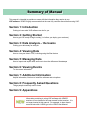
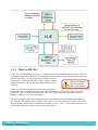
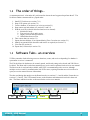
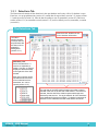
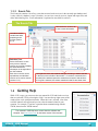
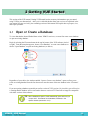
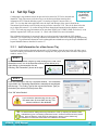
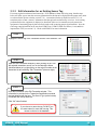
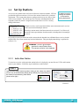
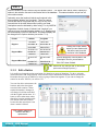
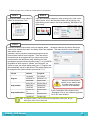
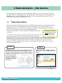
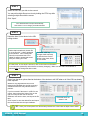
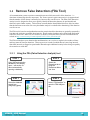
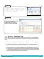
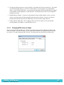
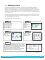
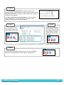
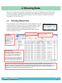
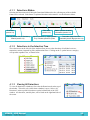
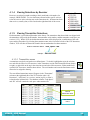
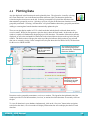
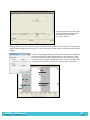
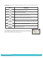
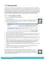
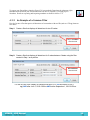
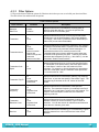
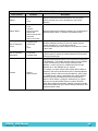
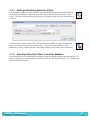
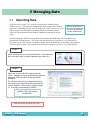
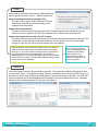
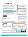
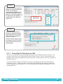
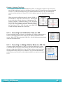
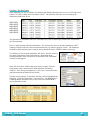
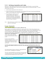
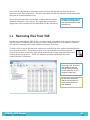
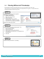
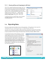
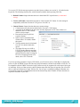

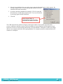
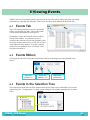
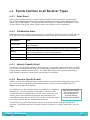
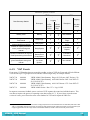
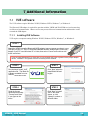
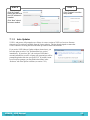
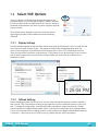
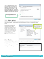
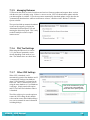
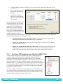
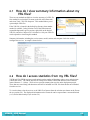
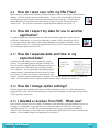
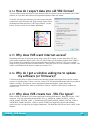
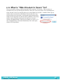
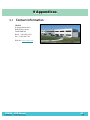
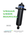


![[1 ] StorageTek SL8500](http://vs1.manualzilla.com/store/data/005684950_1-d7f31af8d49e38e9e4476c8a63e026d0-150x150.png)