1
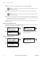
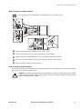
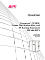
Operation Symmetra® PX UPS, Power Distribution Unit, and XR Battery Enclosure 160 kW 400 V SY160K160H PDUM160H-B SYCFXR9 About this Manual This manual is for the 160 kW Symmetra® PX UPS, Power Distribution Unit (PDU-XR), and XR Battery enclosure. It refers to important safety warnings and instructions, gives an introduction to the display interface, and provides information on operation and troubleshooting. Companion manuals For additional information, refer to the following Symmetra PX manuals: • Receiving and unpacking (990-3013) • Safety (990-2984) • Installation (990-3017) • Power module replacement (990-3025) • Battery module replacement (990-2958) Updates to this manual Check for updates at the APC Web site www.apc.com. Look for the latest letter version of the manual. 990-3015-001 Symmetra PX 160 kW 400 V Operation i Contents Safety ................................................................................ 1 Overview........................................................................... 3 User Interface. . . . . . . . . . . . . . . . . . . . . . . . . . . . . . . . . . . . . . . . . . . . .3 Interface area . . . . . . . . . . . . . . . . . . . . . . . . . . . . . . . . . . . . . . . . . . . . 3 Display interface . . . . . . . . . . . . . . . . . . . . . . . . . . . . . . . . . . . . . . . . . 4 Menu tree . . . . . . . . . . . . . . . . . . . . . . . . . . . . . . . . . . . . . . . . . . . . . . . 5 Operation.......................................................................... 7 Operation Modes . . . . . . . . . . . . . . . . . . . . . . . . . . . . . . . . . . . . . . . . . .7 Normal operation . . . . . . . . . . . . . . . . . . . . . . . . . . . . . . . . . . . . . . . . . 7 Battery operation . . . . . . . . . . . . . . . . . . . . . . . . . . . . . . . . . . . . . . . . . 7 Bypass operation . . . . . . . . . . . . . . . . . . . . . . . . . . . . . . . . . . . . . . . . . 7 Wrap-around maintenance bypass (optional) . . . . . . . . . . . . . . . . . . 7 Operation Procedures. . . . . . . . . . . . . . . . . . . . . . . . . . . . . . . . . . . . . .8 Total Power Off procedure . . . . . . . . . . . . . . . . . . . . . . . . . . . . . . . . . 8 How to turn the load on/off using the display interface . . . . . . . . . . 9 How to put the UPS in maintenance bypass operation . . . . . . . . . . 9 How to return to normal operation . . . . . . . . . . . . . . . . . . . . . . . . . . 11 How to view the Status screens . . . . . . . . . . . . . . . . . . . . . . . . . . . . 12 How to view the Log screen . . . . . . . . . . . . . . . . . . . . . . . . . . . . . . . 12 Configuration ................................................................. 13 System Settings. . . . . . . . . . . . . . . . . . . . . . . . . . . . . . . . . . . . . . . . . .13 How to change the date and time . . . . . . . . . . . . . . . . . . . . . . . . . . . 13 How to change the settings . . . . . . . . . . . . . . . . . . . . . . . . . . . . . . . 13 990-3015-001 Symmetra PX 160 kW 400 V Operation iii Maintenance................................................................... 15 Parts Replacement . . . . . . . . . . . . . . . . . . . . . . . . . . . . . . . . . . . . . . . 15 How to determine if you need a replacement part . . . . . . . . . . . . . 15 How to return parts to APC . . . . . . . . . . . . . . . . . . . . . . . . . . . . . . . . 15 Replacement parts . . . . . . . . . . . . . . . . . . . . . . . . . . . . . . . . . . . . . . 16 How to remove a power module . . . . . . . . . . . . . . . . . . . . . . . . . . . . 17 How to install a power module . . . . . . . . . . . . . . . . . . . . . . . . . . . . . 17 How to replace a power management peripheral . . . . . . . . . . . . . . 18 How to replace an intelligence module (MIM/RIM) . . . . . . . . . . . . . 18 How to replace a battery module . . . . . . . . . . . . . . . . . . . . . . . . . . . 19 How to replace a power distribution module . . . . . . . . . . . . . . . . . 19 Troubleshooting ............................................................ 21 UPS Alarms . . . . . . . . . . . . . . . . . . . . . . . . . . . . . . . . . . . . . . . . . . . . . 21 Modular Distribution fault list . . . . . . . . . . . . . . . . . . . . . . . . . . . . . . 25 PDU fault list . . . . . . . . . . . . . . . . . . . . . . . . . . . . . . . . . . . . . . . . . . . . 26 iv Symmetra PX 160 kW 400 V Operation Safety Warning: All safety instructions in the Safety sheet (990-2984) should be read, understood, and followed prior to handling the system. Failure to do so could result in equipment damage, serious injury, or death. For safety reasons, only the following parts are replacable. If other components of the system require maintenance, contact APC Customer Support using the phone numbers on the back cover of this manual. • power distribution module • power modules • batteries • intelligence modules (MIM/RIM) • peripheral cards 990-3015-001 Symmetra PX 160 kW 400 V Operation 1 Overview User Interface Interface area LOAD POWERED LED When green, power to the load is on. When flashing yellow, the load is supplied through the batteries or the unit is in bypass. CHECK LOG LED When green, a new event has been added to the event log. WARNING LED When yellow, there are one or more warning alarms in the system. CRITICAL LED When red, there are one or more critical alarms in the system. LCD SCREEN Displays alarms, status data, instructional help, and configuration items. UP AND DOWN KEYS Scrolls through menu items. ENTER Opens menu items and confirms changes to system parameters. HELP Opens context-sensitive help. ESC Returns to previous screen. N 990-3015-001 Symmetra PX 160 kW 400 V Operation 3 Overview: User Interface Display interface Overview screens. When the system is running, the display will scroll through screens showing information about the system, and any active alarms. Note: The data values shown are for example only. No Active Alarms System Date/Time: 28-Mar-2007 10:37:01 Volts Out L1: 230 L2: 230 L3: 230 Out L1: L2: L3: Amps 162 151 144 Volts In L1: 230 L2: 230 L3: 230 kW 37.3 34.7 33.1 %kW 70 65 62 Symmetra PX 160 kW Runtime: 1hr 1-min Capacity 100% UPS Load: 70% System Bypass State: UPS Operation UPS State: On Line Note: Press ENTER to go from any overview screen to the main menu screen. Main menu screen. Use the main menu screen to configure and monitor the system using the UPS, Power Dist, Switch Gear, Environment, Alarms, Log, Admin, and Help menu screens. Use the UP and DOWN arrow keys to navigate through the menu screens. The selector arrow is controlled by the UP and DOWN keys. Press ENTER to open the menu marked by the arrow. 4 UPS Power Dist Switch Gear Environment Symmetra PX 160 kW 400 V Operation Alarms Log Admin Help 990-3015-001 Overview: User Interface Menu tree Main Menu Power Dist UPS UPS Power Control Switch Gear Environment Status Input Contacts Total Loading UPS Status UPS Tests & Diags UPS Configuration Alarms View All Alarms View by Severity View by Type Modular Loading Output Relays Factory Alarm Relay Map Volt-Meter Env Monitoring Card Subfeeds Log Help Admin View New Log Items System/ Network View Entire Log Clear Entire Log System ID Manufacturer Data Firmware Updates Caution: Do not make changes to any screens that are not described in this manual without the assistance of APC Customer Support. For APC World-Wide Customer Support telephone numbers, see the back cover of this manual. 990-3015-001 Symmetra PX 160 kW 400 V Operation 5 Operation Operation Modes In an installation without a maintenance bypass panel, the UPS has four different operation modes. If the installation includes a PDU-XR or an external maintenance bypass panel, wrap-around maintenance bypass mode will also be available. Normal operation During normal operation, the UPS converts mains/utility power to conditioned power for the connected loads. Battery operation During battery operation, the UPS provides power to the connected loads from its external batteries for a finite period. The UPS transfers to battery operation if the supply of mains/utility power fails, or is outside pre-defined limits. Bypass operation Bypass is a feature that keeps the load supplied with mains/utility power during maintenance of the UPS power sections. In bypass, mains/utility power is sent directly to the connected load bypassing all internal UPS functions and filters. Battery back up is not available in bypass operation. Wrap-around maintenance bypass (optional) The UPS can be connected to a PDU-XR or an optional external maintenance bypass panel. When activated, this panel bypasses the UPS, feeding mains/utility power directly to the load. An activated wrap-around maintenance bypass panel completely isolates the UPS and allows maintenance to be performed - including a replacement of the entire UPS. 990-3015-001 Symmetra PX 160 kW 400 V Operation 7 Operation Procedures Note: If the system does not contain a PDU-XR, the Q1, Q2, Q3, and Q5 switches are located on an optional external maintenance bypass panel. Refer to the documentation included with the maintenance bypass panel for additional information. Total Power Off procedure Warning: Before electrical installation begins, verify that the UPS is in the Total Power Off mode by following this procedure. UPS XR Battery enclosures / PDU-XR ON TRIP OFF Set the SYSTEM ENABLE switch to the the OFF position. Set the DC DISCONNECT switch on all XR Battery enclosures and on the back of the PDU-XR to the OFF position. Disconnect all battery units by removing them or pulling them out to the red disconnect line. Caution: To ensure the enclosure does not tip, do not pull the battery units out beyond the red disconnect line unless you completely remove them from the enclosure. 8 Symmetra PX 160 kW 400 V Operation 990-3015-001 Operation: Operation Procedures Set the upstream mains power to the OFF or LOCKED OUT position. If the UPS has a dual mains supply, set both supplies to the OFF or LOCKED OUT position. Electrical Hazard: Follow proper Lockout/Tagout procedures to remove access to the unit and physically label the unit as intentionally out of service. How to turn the load on/off using the display interface Press UPS Power Dist Switch Gear Environment Alarms Log Admin Help UPS UPS UPS UPS Power Control Status Tests & Diags Configuration Press Press Turn UPS Off Reboot UPS UPS Into Bypass UPS To Sleep How to put the UPS in maintenance bypass operation Use the display to put the UPS into bypass. UPS Power Dist Switch Gear Environment Alarms Log Admin Help Press Press Turn UPS Off Reboot UPS UPS into Bypass UPS to Sleep Putting UPS Into Bypass, please wait... UPS UPS UPS UPS Power Control Status Tests & Diags Configuration Confirm: UPS into Bypass? NO, ABORT YES, Into Bypass Press Press UPS is now in bypass, press any key to return to previous menu Confirm the transfer into bypass is complete. Note: The H3 LED next to the Q3 switch on the PDU-XR will illuminate, indicating that it is safe to operate the Q3 switch. Set the Q3 switch on the PDU-XR to the ON position. Note: The H2 LED beside the Q2 switch will illuminate, indicating that it is safe to operate the Q2 switch. 990-3015-001 Symmetra PX 160 kW 400 V Operation 9 Operation: Operation Procedures Set the Q2 switch on the PDU-XR to the OFF position. Turn the UPS off using the display. UPS Power Dist Switch Gear Environment Alarms Log Admin Help Press Press UPS UPS UPS UPS Notify PowerChute? Cancel Yes, Notify Servers No, Don’t Notify Turn UPS Off Reboot UPS UPS into Bypass UPS to Sleep Power Control Status Tests & Diags Configuration Press Press Turn UPS Off With Server Notification? >NO, ABORT >YES, Turn UPS Off Turning UPS off, please wait... Set the Q1 switch on the PDU-XR to the OFF position. Set the Q5 switch on the PDU-XR to the OFF position. Set the UPS SYSTEM ENABLE switch to the OFF position. Set the DC DISCONNECT switch on all of the XR Battery enclosures and the PDU-XR to the OFF position. 10 Symmetra PX 160 kW 400 V Operation 990-3015-001 Operation: Operation Procedures How to return to normal operation Set the DC DISCONNECT switch on all of the XR Battery enclosures and the PDU-XR to the ON position. Set the Q1 switch on the PDU-XR or external maintenance bypass panel to the ON position. Set the Q5 switch on the PDU-XR or external maintenance bypass panel to the ON position. Set the SYSTEM ENABLE switch on the UPS to the ON position. Note: Wait approximately 30 seconds for system to start. Using the display interface, select the following: 990-3015-001 Press UPS Power Dist Switch Gear Environment Alarms Log Admin Help Press Turn UPS On UPS On Into Bypass Press UPS UPS UPS UPS Control Status Tests & Diags Configuration Press UPS Load is ON. Symmetra PX 160 kW 400 V Operation 11 Operation: Operation Procedures Press ESC to go back to the UPS Control screen and select UPS into Bypass. Note: The H2 LED next to the Q2 switch will illuminate, indicating that it is safe to operate the Q2 switch. Set the Q2 switch on the PDU-XR or external maintenance bypass panel to the ON position. Note: The H3 LED next to the Q3 switch will illuminate, indicating that it is safe to operate the Q3 switch. Set the Q3 switch on the PDU-XR or external maintenance bypass panel on the PDU-XR to the OFF position. As soon as the Q3 switch is in the OFF position, the UPS will automatically return from maintenance bypass operation to normal operation. The UPS is now in normal operation. Verify that the Load Powered LED is lit and the system is not displaying any alarms. How to view the Status screens Use the main menu screen to access information for each component of the system. A status screen is available for each component, this example uses the UPS. Press UPS Power Dist Switch Gear Environment Alarms Log Admin Help Symmetra PX 160 kW On Line Press UPS UPS UPS UPS Control Status Tests & Diags Configuration Press Use the UP and DOWN arrow keys to navigate through the Status screens. No UPS Alarms How to view the Log screen Press UPS Power Dist Switch Gear Environment Alarms Log Admin Help Log Item > 1 of 2 <Description> Press View New Log Items View Entire Log Clear Entire Log Use the UP and DOWN arrow keys to navigate through the Log screens. 03/14/07 10:37:02 12 Symmetra PX 160 kW 400 V Operation 990-3015-001 Configuration System Settings How to change the date and time Use the UP and DOWN arrow keys to navigate through the menu screens. To change a setting, press ENTER and use the UP and DOWN arrow keys to change the selection. Press ENTER to save the changes. Press UPS Power Dist Switch Gear Environment Alarms Log Admin Help Press System Password Date/Time Local Interface Network Address Press System/Network System ID Manufacturer Data Firmware Update Press Date:>01Mar>2007 Time:>02>24>00 How to change the settings Use the arrow keys to navigate through the menu screens. To change a setting, press ENTER and use the UP and DOWN arrow keys to change the selection. Press ENTER to save the changes. 990-3015-001 Press UPS Power Dist Switch Gear Environment Alarms Log Admin Help Press System Password Date/Time Local Interface Network Address Press System/Network System ID Manufacturer Data Firmware Update Press Contrast>4 Key Click>On Beeper Volume>High Alarm Beeper>On Symmetra PX 160 kW 400 V Operation 13 Maintenance Parts Replacement How to determine if you need a replacement part To determine if you need a replacement part, contact APC Customer Support and follow the procedure below so that the APC Customer Support representative can assist you promptly: 1. In the event of a module failure, the display interface may show additional “fault list” screens. Press any key to scroll through these fault lists, record the information, and provide it to the representative. 2. Write down the serial number of the unit so that you will have it easily accessible when you contact APC Customer Support. 3. If possible, call APC Customer Support from a telephone that is within reach of the UPS display interface so that you can gather and report additional information to the representative. 4. Be prepared to provide a detailed description of the problem. A representative will help you solve the problem over the telephone, if possible, or will assign a return material authorization (RMA) number to you. If a module is returned to APC, this RMA number must be clearly printed on the outside of the package. 5. If the unit is within the warranty period, repairs or replacements will be performed free of charge. If it is not within the warranty period, there will be a charge. 6. If the unit is covered by an APC service contract, have the contract available to provide information to the representative. How to return parts to APC Call APC Customer Support to obtain an RMA number. To return a failed module to APC, pack the module in the original shipping materials, and return it by insured, prepaid carrier. The APC Customer Support representative will provide the destination address. If you no longer have the original shipping materials, ask the representative about obtaining a new set. Pack the module properly to avoid damage in transit. Never use styrofoam beads or other loose packaging materials when shipping a module. The module may settle in transit and become damaged. Enclose a letter in the package with your name, RMA number, address, a copy of the sales receipt, description of the problem, a phone number, and a check as payment (if necessary). Note: Damages sustained in transit are not covered under warranty. 990-3015-001 Symmetra PX 160 kW 400 V Operation 15 Maintenance: Parts Replacement Replacement parts Part APC Part No. 16 kW power module SYPM10K16H Battery module SYBT9-B4 Intelligence Module (MIM) OG-SYMIM16 APC SS Call-UPS II Accessory card AP9608 Smartslot relay I/O Module AP9610 UPS Network Management card AP9617 UPS Network Management card with Environmental Monitoring and Out of Band Management card AP9618 UPS Network Management card with Environmental Monitoring AP9619 Modbus/Jbus Interface card AP9622 Power Distribution Module Go to www.apc.com for a complete list of breaker modules. Warning: Only trained persons familiar with the construction and operation of the equipment, as well as the electrical and mechanical hazards involved, may install and remove system components. Before removing any power modules, make sure that the remaining power modules can support the load. 16 Symmetra PX 160 kW 400 V Operation 990-3015-001 Maintenance: Parts Replacement How to remove a power module Use two people to lift components weighing between 18–32 kg/40–70 lb. 1 1 Turn the locking latch down until the arrow points down. Unscrew the spring-activated knobs on both sides of the module. Pull the module out of the enclosure as far as the lock mechanism will allow. Release the lock by pushing the black plastic tab on each side of the module. Pull the module up and out of the enclosure. How to install a power module Reverse the procedure for installation of the replacement module. The display interface will indicate that the system has recognized a new module. Caution: Secure the locking latch before tightening the spring-activated knobs on the module to ensure that the module makes proper contact in the unit. The power module will not operate unless the locking latch is locked. 990-3015-001 Symmetra PX 160 kW 400 V Operation 17 Maintenance: Parts Replacement How to replace a power management peripheral Only the cards installed in these two space can be replaced. Loosen the two Phillips screws on both sides of the card and carefully pull it out of the enclosure. Note: Reverse the procedure to install a replacement card. The display interface will show a message when it has registered a new card. How to replace an intelligence module (MIM/RIM) Loosen the two Phillips screws on both sides of the module. When the screw on left side is loose, the module will be de-activated. The display interface will show a message that the number of modules has decreased. Reverse this procedure to install replacement modules. Note: If two intelligence modules are functioning, one can be replaced without interrupting the UPS. 18 Symmetra PX 160 kW 400 V Operation 990-3015-001 Maintenance: Parts Replacement How to replace a battery module . Use two people to lift components weighing between 18–32 kg/40–70 lb. Holding the handle, gently lift the battery unit and pull it halfway out. A lock mechanism prevents it from being pulled all the way out. Release the lock by pushing the battery unit upwards and pull the battery unit all the way out while supporting it Take the replacement battery unit and push it into the system. Note: Allow for a 24-hour recharging period of the batteries after system start-up/battery replacement for battery monitoring data to become fully reliable. How to replace a power distribution module Disconnect the power cable from the power distribution module from the extension cable. Open the locking latch on the module and gently pull it out of the enclosure. Reverse the procedure to install the new module. 990-3015-001 Symmetra PX 160 kW 400 V Operation 19 Troubleshooting UPS Alarms This section lists all of the alarm and status messages that might be displayed on the display interface. A suggested corrective action is listed with each message to help to troubleshoot the problem. Note: If a problem is reported, ensure that the system component in question is correctly installed. 1 Display Message Meaning Corrective Action Battery Charger Fault The battery charger is not functioning properly. Contact APC Customer Support. Battery Fault A battery module has failed and requires replacement. See “How to replace a battery module” on page 19. Battery High Temperature Violation The temperature of one or more battery units has exceeded system specifications. Ensure that the ambient temperature meets the specifications of the system. If the ambient temperature is below 40°C (104°F). Initiate a self-test to detect any bad battery units. Replace any bad battery units. Battery High Voltage Violation The battery voltage is too high and the charger has been deactivated. Contact APC Customer Support. Battery Monitor Card Fault The battery monitor card has failed. See “How to replace a power management peripheral” on page 18. Battery Monitor Card Removed The battery monitor card has been removed. If the battery monitor card has not been removed, check that is has been properly inserted. Bypass Relay Stuck in Bypass Mode The system is stuck in bypass mode and cannot return to normal operation. Check the static bypass switch. Contact APC Customer Support. Bypass Relay Stuck in Online Mode The system is stuck in online mode and cannot go into bypass. Check the static bypass switch. Contact APC Customer Support. Communication Lost While On Internal communications in the Battery system have failed. Contact APC Customer Support. Discharged Battery The UPS is online and the battery charge is low. No corrective action necessary. Note: If the input voltage fails, runtime will be limited. Extended Run Frame Fault One of the battery frames has failed. Contact APC Customer Support. 990-3015-001 Symmetra PX 160 kW 400 V Operation 21 Troubleshooting: UPS Alarms Display Message Meaning Corrective Action External DC Disconnect Switch The external DC DISCONNECT switch Open tripped. Battery power is not available or the runtime is lower than expected. Close the external DC DISCONNECT switch. Check the fuse on the XR battery enclosure. If the fuse has blown, contact APC Customer Support. External Switch Gear Communication Card Fault See “How to replace a power management peripheral” on page 18. The external switch gear communication card has failed. External Switch Gear The system no longer detects an Option 1: Ensure the external switch gear Communication Card Removed external switch gear communication communication card is installed properly. card. Option 2: Replace the external switch gear communication card. Graceful Shutdown Initiated A graceful shutdown or reboot has been initiated from the display interface or other accessory. No corrective action necessary. High Isolation Transformer Temperature The isolation transformer temperature is too high. Contact APC Customer Support. Internal Communications Failed One of the buses used for the communication between the UPS modules has failed. Contact APC Customer Support. In Bypass: Hardware Fault The system has transferred into Contact APC Customer Support. bypass because a fault has occurred. In Bypass: Overload The system has transferred into bypass because the load has exceeded the power capacity of the system. In Bypass: User-Initiated The system has been transferred into Check for any problems with the system. bypass due to user action. Transfer the system to normal operation. Input Voltage or Frequency Cannot Support Bypass Correct the input voltage to provide The frequency or voltage is out of acceptable voltage or frequency. acceptable range for bypass. This message occurs when the UPS is online, and indicates that the bypass mode may not be available if required. Intelligence Module Fault The main intelligence module has failed and requires replacement. Replace the main intelligence module. See “How to replace an intelligence module (MIM/RIM)” on page 18. Load (kVA) Alarm Violation The load has exceeded the userspecified load alarm threshold. Option 1: Use the display interface to raise the alarm threshold. Option 2: Reduce the load. Local Management-To-UPS Communication Lost Internal communications in the system have failed. Contact APC Customer Support. 22 Option 1: Decrease the load. Option 2: Add a power module to the system. Symmetra PX 160 kW 400 V Operation 990-3015-001 Troubleshooting: UPS Alarms Display Message Meaning Low Battery The UPS is in battery operation and No corrective action necessary. the battery charge is low. Note: Runtime is limited. Shut down the system and the load equipment or restore incoming voltage. No Batteries Detected No battery power is available. Option 1: Ensure the batteries are installed properly. Option 2: Check if the DC Breaker has been tripped. No Power Modules Detected No power modules are available. Option 1: Ensure that the power modules are properly installed, the two fastening screws are tight, and the locking latch is engaged. Option 2: Check for other communication alarm messages. Not Synchronized Fault System cannot synchronize to AC line and bypass mode may not be available. Option 1: Decrease the sensitivity to input frequency. Option 2: Correct the input voltage to provide acceptable voltage frequency. Output Voltage Not In Range The output voltage is not within the specified range. Evaluate the threshold setting. If necessary, adjust it for your situation. Contact APC Customer Support. Overload The load has exceeded the system power capacity. Option 1: Decrease the load. Option 2: Add a power module to the system. Power Failure The input voltage is not acceptable for normal operation. Contact APC Customer Support. Power Module Fault A power module has failed and requires replacement. See “How to remove a power module” on page 17. Redundancy Alarm Actual power module redundancy has fallen below user-specified redundancy alarm threshold. At least one power module has failed or the load has increased. Option 1: If possible, install additional power modules. See “How to install a power module” on page 17. Option 2: Replace failed modules. See “How to replace a power distribution module” on page 19. Option 3: Reduce the load. Option 4: Change alarm limit. Redundancy Lost The UPS no longer detects redundant power modules. One or more power modules have failed, or the load has increased. Option 1: Install additional power modules. Option 2: Replace failed modules. See “How to remove a power module” on page 17. 990-3015-001 Corrective Action Symmetra PX 160 kW 400 V Operation 23 Troubleshooting: UPS Alarms Display Message Meaning Corrective Action Redundant Intelligence Module The redundant intelligence module Replace the redundant intelligence module. Fault has failed and requires replacement. See “How to replace an intelligence module (MIM/RIM)” on page 18. Replace the main intelligence module. See Redundant Intelligence Module The main intelligence module has “How to replace an intelligence module in Control failed, the redundant intelligence module is functioning as the primary (MIM/RIM)” on page 18. intelligence module. Replacement Battery Needed One or more battery units needs to be replaced. See “How to replace a battery module” on page 19. Runtime Alarm The predicted runtime is lower than the user-specified minimum runtime alarm threshold. At least one battery module has failed or the load has increased. Option 1: Install additional battery modules. Option 2: Replace failed battery modules. Option 3: Reduce the load. Option 4: Change the alarm limit. Site Wiring Fault There is a problem with the phase rotation or a phase is missing in the input voltage to the UPS. Contact APC Customer Support. Static Bypass Switch Module Fault The static bypass switch module has Contact APC Customer Support. failed and requires replacement. Static Bypass Switch Module Removed The system no longer detects a static Option 1: Ensure the static bypass switch bypass switch module. module is installed properly. Option 2: Replace the static bypass switch module. System ID Card Fault The system ID card has failed and requires replacement. See “How to replace a power management peripheral” on page 18. System ID Card Removed The system no longer detects a system ID card. Option 1: Ensure the system ID card is installed properly. Option 2: Replace the system ID card. System Level Fan Fault The system level fan has failed and requires replacement. Contact APC Customer Support. System Power Supply Card Fault The system power supply card has failed and requires replacement. See “How to replace an intelligence module (MIM/RIM)” on page 18. System Start-Up Configuration The system configuration download Check for other alarms and contact APC Fault failed. Unable to determine the Customer Support. system voltage or frame size. XR Communication Card Fault The XR communication card has failed and requires replacement. See “How to replace a power management peripheral” on page 18. XR Communication Card Removed Option 1: Ensure card is installed properly. Option 2: Replace the card. 24 The system no longer detects a XR communication card. Symmetra PX 160 kW 400 V Operation 990-3015-001 Modular Distribution fault list The display interface will identify the number of the power distribution module that has caused an alarm or warning. Display Message Meaning Corrective Action High Module Current The high module current threshold has been exceeded. Evaluate the threshold setting. If necessary, adjust it for your situation. High Subfeed Current The high subfeed current threshold has been exceeded. Evaluate the threshold setting. If necessary, adjust it for your situation. Low Module Current The low module current threshold has been exceeded. Evaluate the threshold setting. If necessary, adjust it for your situation. Low Subfeed Current The low subfeed current threshold has been exceeded. Evaluate the threshold setting. If necessary, adjust it for your situation. Maximum Module Current The maximum module current threshold has been exceeded. Evaluate the threshold setting. If necessary, adjust it for your situation. Maximum Subfeed Current The maximum subfeed current threshold has been exceeded. Evaluate the threshold setting. If necessary, adjust it for your situation. Minimum Module Current The minimum module current threshold has been exceeded. Evaluate the threshold setting. If necessary, adjust it for your situation. Minimum Subfeed Current The minimum subfeed current threshold has been exceeded. Evaluate the threshold setting. If necessary, adjust it for your situation. Modular Distribution Communication Communication has been lost with the modular distribution breakers. Check the communication cables to ensure they are properly connected. Contact APC Customer Support. Module Breaker Open A modular circuit breaker is open. Check the modular circuit breakers to see if one has overloaded. Replace if necessary. Subfeed Breaker Open A subfeed circuit breaker is open. Check the subfeed circuit breakers to see if one has been over-loaded. 990-3015-001 Symmetra PX 160 kW 400 V Operation 25 PDU fault list Display Message Meaning Maintenance Bypass Alarm The system is in maintenance bypass: the Q2 switch is open and the Q3 switch is closed. 26 Corrective Action No corrective action necessary. Output V <Ln-N> Voltage Under Limit Phase-to-neutral output voltage Evaluate the threshold setting. If necessary, for phase <L-N> has dropped adjust it for your situation. below the configured limit. Output V <Ln-N> Voltage Over Limit Phase-to-neutral output voltage Evaluate the threshold setting. If necessary, for phase <L-N> exceeded the adjust it for your situation. configured limit. Output I L<n> Current Over Limit Current of output phase <n> exceeded the configured limit. Evaluate the threshold setting. If necessary, adjust it for your situation. Output I L<n> Current Under Limit Current of output phase<n> dropped below the configured limit. Evaluate the threshold setting. If necessary, adjust it for your situation. Output FDev Freq Out of Range Frequency of the output current Evaluate the threshold setting. If necessary, is above or below the range that adjust it for your situation. is configured as acceptable. <User Contact Name> Alarm Active A user-configured contact connected to the system is reporting an alarm condition. No UPS Input Breaker Q1 Open The Q1 circuit breaker is open, Close the Q1 switch to re-connect the UPS to utility/mains power. and the UPS is disconnected from the input voltage. No Panel Feed Breakers Q2 & Q3 Open The Q2 & Q3 circuit breakers are open, and the system is not supporting connected equipment. For safety reasons, ensure the switches were not closed for maintenance purposes. If not, close Q2 for UPS operation, and Q3 for maintenance bypass. Atypical Bypass Mode Alarm The system state as set by the Q1, Q2, & Q3 breakers is in a non-typical bypass mode. Option 1: Resume normal UPS operation. Option 2: Go to maintenance bypass. Determined why the alarm has occurred. This is a user-specific alarm setting. Symmetra PX 160 kW 400 V Operation 990-3015-001 APC Worldwide Customer Support Customer support for this or any other APC product is available at no charge in any of the following ways: • Visit the APC Web site to access documents in the APC Knowledge Base and to submit customer support requests. – www.apc.com (Corporate Headquarters) Connect to localized APC Web sites for specific countries, each of which provides customer support information. – www.apc.com/support/ Global support searching APC Knowledge Base and using e-support. • Contact an APC Customer Support center by telephone or e-mail. – Regional centers Direct InfraStruXure Customer Support Line (1)(877)537-0607 (toll free) APC headquarters U.S., (1)(800)800-4272 (toll free) Canada Latin America (1)(401)789-5735 (USA) Europe, Middle East, Africa (353)(91)702000 (Ireland) Western Europe +800 0272 0272 (including Scandinavia) Japan (0) 35434-2021 Australia, New Zealand, (61) (2) 9955 9366 (Australia) South Pacific area – Local, country-specific centers: go to www.apc.com/support/contact for contact information. Contact the APC representative or other distributor from whom you purchased your APC product for information on how to obtain local customer support. Entire contents copyright 2007 American Power Conversion Corporation. All rights reserved. Reproduction in whole or in part without permission is prohibited. APC, the APC logo, and Symmetra are trademarks of American Power Conversion Corporation. All other trademarks, product names, and corporate names are the property of their respective owners and are used for informational purposes only. 990-3015-001 *990-3015-001* 04/2007