1
~
~
t:
I
I
I
<
I
:
QIHJ}lO
.'
lonuOII\I
S,J8Sn'
1994,Orchid Technology. This manual is copyrighted. All rights reserved.
document may not, in whole or part, be copied, reproduced, reduced or
1I',ldled by any means, either mechanical or electronic, without prior consent
wilting from Orchid Technology, Incorporated.
I hill
IIIi
III
I I'" III M and Orchid are trademarks of Orchid Technology. All other products
in this manual are trademarks of their respective manufacturers.
1111III II IIwd
Orchid Technology
45365Northport Loop West
Fremont, CA 94538-9973
L~
I
Iii
TABLEOF CONTENTS
Foreword
Introduction
About ThisManual
Important - Before You Begin
5
6
7
8
SECTION 1
Installing Kelvin 64
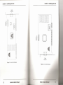
Fig. 1.1: Kelvin 64/VLB Diagram
Fig. 1.2: Kelvin 64/PCI Diagram
Fig. 1.3: Kelvin 64/SA Diagram
11
12
13
14
Step 1: Preparing Your Computer
15
Step 2: Preparing Your Kelvin 64
Adding Memory
15
15
Step 3: Installing Your Kelvin 64
16
16
17
Fig. 1.4: Rear Slot Cover
Fig. 1.5: Standard
15-pin D-shell Connector
SECTION 2
Device Drivers and Utilities
Before You Begin
Installation
Using KINSTALL.EXE
Fig. 2.1: KINSTALL Main Menu Screen
Network Considerations
Microsoft Windows Driver Installation
Fig. 2.2: Kelvin 64 Setup Menu
Menu Features
Ig. 2.3: Inquiry Option
1·1C).2.4: Inquiry Option
Defined
Kelvin 64 User's Manual
19
19
20
20
20
21
21
21
22
22
22
1
-==
I
Center Window
Fig. 2.5: Center Window Option
Green PC
24
24
Screen Saver Option
Fig. 2.6: Screen Saver Option
39
Green PC Feature
39
25
Big Picture Feature
25
Virtual Screen
25
26
Magnification
Fig. 2.7: Magnification Option
27
UtilitySoftware
41
Index
42
27
Fig. 2.8: KSCAN Main Menu
28
Selecting Your Monitor Type
28
Fig. 2.9: Monitor Type Setup
29
Monitor Setup
Fig. 2.10: Advanced
FCC Notice
27
Using KSCAN
Advanced
ApPENDIX B
23
23
Option
29
Monitor Type Setup
30
Video Modes
ApPENDIX A
Technical Help and Information
31
Troubleshooting the Kelvin 64
31
Technical
34
Information
Specifications
34
Additional
35
Features
Memory Address Setting
36
VESA Support
36
I low 10 obtain the Memory Upgrade
Kit
Kolvln 611 Resolutions and Refresh Rates
37
I(Ihll) 1\. I: Resolutions and Refresh Rates
37
I ( Jt 111110 Connector
Pin-Outs (VESA Standard)
1(11111)fl.?: VI.SI\ Feoture Connector Pin-outs
2
36
Kelvin 64 User's Manual
38
38
Kelvin 64 User's Manual
3
Orchid Technology has been a leading manufacturer ofhardware and
peripherals for personal computers since its incorporation in 1982,
and is noted for introducing new standards to the personal computer
industry:
1982
PCnet: first personal computer Local Area Network.
1984
PCturbo: first Accelerator card for PC compatible
computers.
1985
ECCELL:first PC Multifunction card with error correction.
1987
RamQuest 50/60: first EMS (Expanded Memory Specification) product for the IBMPS/2 computers.
1990
ProDesigner II: first Beyond Super VGA graphics
adapter to support 1024x 768graphics in 256 colors 01'\
interlaced and non-interlaced monitors.
1991
Fahrenheit 1280°:first to ship a Windows accelerator
based on 53's 86C911chip.
1992
Fahrenheit VA: first to ship a Windows accelerator with
video audio built-in.
1993
CelsiusNLB: first to ship a Windows accelerator based
on lIT's award-winning AGX015chip.
~
ORCHID
4
KelvIn 64 User's Manual
Kelvin 64 User's Manual
5
About ThisManual
Introduction
The Kelvin 64TMis a powerful 64-bit graphics accelerator that provides high-speed horizontal and vertical acceleration in all graphic modes. It uses a full 64bit non-interleaved DRAM interface which is twice
the throughput of 32-bit controllers. The result is top
graphic responsiveness.
Kelvin 64 introduces Green PC Power Management
andVESA Display Power Management Signaling
(DPMS). The Kelvin 64 is the first affordable 64-bit
graphics accelerator for ISA,VL-Bus,PC! and Pentium
systems.
Operating at resolutions up to 1280x1024,the Kelvin
64's powerful 64-bit architecture accelerates all your
modes, provides true high resolution graphiCSand full
VESA compliance. In addition, Kelvin 64 also comes
with a comprehensive range of software enhancements and utility programs that includes the Big
Picture feature, and a user-friendly screen utility that
adjusts the refresh rate and centers the screen without
using conventional memory.
Thank you for purchasing Kelvin 64. Care has been
taken to ensure that it will provide you with years of
lrOLI blc-freeoperation. We believe you will be pleased
with your purchase.
This manual presumes that you are already familiar
with your IBMPC compatible computer. While Kelvin
64 has been designed to be easy to install, we recommend that you refer to your computer's reference
manual when terminology or installation steps are
unfamiliar to you.
This manual has been organized to help you set up and
install Kelvin 64 as quickly as possible. Each section is
divided into short, easy-to-follow steps, to help you
understand the installation and function of Kelvin 64.
Section 1: Installing Kelvin 64
Whether you are a beginner or an experienced user,
this section will give you important information on the
proper installation of Kelvin 64.
Section 2: Device Drivers and Utilities
Here you will be given the information needed to
install high resolution device drivers for AutoCAD,
Windows 3.1, Lotus 1-2-3, WordPerfect and Word.
Kelvin 64 also provides a screen utility that adjusts the
refresh rate and centers the screen.
Appendix A: Technical Help and Information
If you are experiencing installation difficulties or require troubleshooting information, this section will
give you checkpoints to look at to ensure that your
Kelvin 64 is operating properly. Appendix A also
includes information on the technical specifications
and features.
Appendix B:Green PC
Appendix B provides details on the Green PC feature.
6
Kelvin 64 User's Manual
Kelvin 64 User's Manual
7
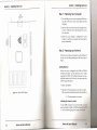
Important! - Before You Begin
This manual contains information for all of the products listed below. All references to "Kelvin 64" will
refer to all of these products, unless otherwise noted.
Kelvin 64NlB
The Kelvin 64/VLB is VL-Bus 2.0 compliant, which
provides a 32-bit direct connect interface. It supports
50MHz operations, uses VESA Local Bus (VL-Bus)
technology for incredibly fast graphics, and is VLBus 1.0 backward compatible.
Kelvin 64/PCI
Kelvin 64/ISA
'I'he I<L'Ivin 64/ISA is the next generation Super VGA
.....
D
Kelvin 64 User's Manual
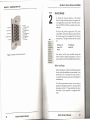
All MS/PC DOS filenames and DOS
commands will be emphasized by this
type style.
Common Names
DPMS
Display Power Management Signaling
ISA
Industry Standard Architecture
PC
Refers to the family of IBM PC, PC/XT or
PC/ AT compatible computers
PCI
Peripheral Component Interconnect
SVGA
SuperVGA
VESA
Video Electronics Standards Association
VGA
Video Graphics Array
Vl-Bus
VESA Local Bus
adapter. Its 64-bit graphics accelerator tech-
IIIlII'IW provides for faster Windows and video per111111"'lll'l'.
It supports resolutions up to 1280x1024
11111 I i IlIIIl'l-, lip to '16.8million.
8
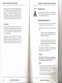
When you see the Magnifying Glass, it
means the text is referring to something you should take a closer look at
before proceeding further.
FILENAMES
The Kelvin 64/PCI provides burst mode technology,
which is required for the fastest graphics possible in
Windows, OS/2, UNIX and other GUI environments.
Its technology provides compatibility with Pentiumbased systems, and because of compatibility with 64bit data access, you will experience data throughput
at impressively high levels.
I',r,q ihlcs
This manual will familiarize you with the features, installation and use of your Kelvin 64. There are several
symbols and conventions used throughout this manual
which will help to draw your attention to a feature or to
focus on important information:
Kelvin 64 User's Manual
9
Section 1: Installing Kelvin 64
Section
1
INSTALLING KELVIN 64
The Kelvin 64 graphic cards are designed to be easyto-use and easy-to-install. There are three fundamental steps to the installation:
Step 1: Preparing your Computer
STATIC!
Before
handling the
Kelvin 64, be
sure to
guard
against
electrostatic
discharge.
Do not wear
clothing that
causes static
(such as
wool
sweaters).
Inmost
cases,
touching the
power
supply
housing
before
handling the
card will
discharge
static
electricity, or
you may
want to buy
a Ground
strap from
your local
computer
store.
10
Kelvin 64 User's Manual
You will need to take the cover off your computer and
prepare an expansion slot for your Kelvin 64.
Step 2: Preparing your Kelvin 64
There are no switches or jumpers to set for Kelvin 64.
If you want to add memory to Kelvin 64 at this time
or later, this step gives you details on the memory
required.
Step 3: Installing your Kelvin 64
Once the Kelvin 64 has been securely seated in the
computer and the cover replaced, the Kelvin 64 will
be ready to operate.
Kelvin 64 User's Manual
11
Section 1: Installing Kelvin 64
Section 1: Installing Kelvin 64
15-pin
Connector
/
='
o
Q)t5
~
01
Q)
.3c
CIl c
Q)
0
u..O
=
§
=
0
[ij
o
00=
g
U)
g
g
go g
g en g
~
W][JJlmWl
=
=
=
=
=
=
=
s
00=
s
c::::J
0,
~I
o
c::::J
§
§
c:::::J
00=
=
=
I~
(j)
g
aJ
Q
~;
o
o
Q)t5
~
Q)
.3 c
c
Q)
0
u..O
CIl
1111111111111111111111111111111
g
I 101
=
=
=
=
=
=
=
=
=
=
~
§
/
15-pin
Connector
Figure 1.1: Kelvin 64/VLB Diagram
Figure 1.2:
Kelvin 64 User's Manual
=
=
=
=
=
=
=
~
=
12
=
=
=
=
lWWllWlW~
=
=
=
=
=
=
=
=
=
=
=
=
~
=
=
=
=
,=
....,
IIIIIIIIIIUIIIIIIIIIIIIIIIIIII
::c:
u
0:::
=
=
=
Kelvin 64/PCI Diagram
Kelvin 64 User's Manual
Section 1: Installing Kelvin 64
Section 1: Installing Kelvin 64
Step 1: Preparing Your Computer
15-pin
Connector
1. Turn off the power to your computer and disconnect all of the power cords and cables from the
computer.
rrnr-'"lrrn
II
ral
••
'---
.9
Q)
~
.a
C1l
U
Q)
c I-c
0
LLO
Q)
0
0
0
0
0
0
0
0
0
~
00
00
00
00
00
00
00
00
00
00
0'.."-
0
0
0
0
0
~
(f)
a
[0
0
0
0
0
0
0
0
0
0
0
0
0
0
0
=
=
=
=
=
=
=
=
=
=
=
=
=
=
=
=
=
=
=
=
=
=
=
=
=
~D~
i ,
1111111111111111111111111111111
1111111111111111111111111111111
unnn
Figure 1.3:
Kelvin 64/1SA Diagram
=
=
=
=
=
=
=
=
=
=
=
=
=
=
=
=
=
=
~
2. Remove the screws that secure the computer chassis cover. Slide the cover off and keep the screws
in a safe place.
3. Make sure your system is configured for color
display. Consult your computer user's manual for
more information.
Step 2: Preparing your Kelvin 64
There are no switches or jumpers to set for Kelvin 64.
If you are not adding memory at this time, skip to
Step 3.
Adding Memory
Kelvin 64 comes configured with 1MB of DRAM
(Dynamic Random Access Memory) and is easily
upgraded to 2MB. The additional memory is automatically detected by Kelvin 64, and must meet the
following specifications:
• 256K x 16 DRAM
• Operate at 70 nanoseconds access time or faster.
The access time is indicated on the chip as follows:
-7 = 70 nanoseconds access time
Installing the memory chips:
To add 1MB of memory to your Kelvin 64, you will
need to install two 256Kx 16DRAM chips into BAN
1. See the following steps for proper installauon:
14
Kelvin 64 User's Manual
Kelvin 64 User's Manual
Section 7: Installing Kelvin 64
Section 1: Installing Kelvin 64
NOTE: Avoid electrostatic discharge when handling the
memory chips. Be properly grounded by touching the
power supply housing or by using a Ground Strap.
1. To install a memory chip, position it over the empty socket. ~
Make sure that the writing on the ~
chip is facing the same direction
as the memory chips already
installed.
Once you have prepared your Kelvin 64, you are
ready to install Kelvin 64 and connect your monitor.
1. Select an expansion slot for Kelvin 64. Depending
on what card you have, select a 32-bit VL-Bus slot for
the Kelvin 64/VLB, or a 32-bit PC! slot for the Kelvin
64/PCI, or a 16-bit ISA slot for the Kelvin 64/ISA.
2. Remove the rear slot cover bracket if it is present
and keep the screw for future use.
2. Place the memory chip down into
the socket.
3. Use your thumbs to evenly press
each side of the memory chip
down into the socket. You will
hear a small "snap" as the chip ~
is fully installed.
~
The memory installation is now
complete.
Step 3: Installing Your Kelvin 64
I
,
.,.
Figure 1.4: Rear slot cover
3. Carefully hold Kelvin 64 by the top edges and
lower it into its expansion slot. Ensure that Kelvin
64 seats firmly into the slot, and that it aligns
properly with the computer's backplane.
4. Secure Kelvin 64 in place by fastening its metal
bracket to the computer backplane (use the screw
you removed).
5. Reconnect previously removed cables and power
cords and replace the cover of the computer.
6. Connect your monitor cable to the IS-pin monitor
connector on Kelvin 64 (see Figure 1.5).
Kelvin 64 installation is complete.
76
Kelvin 64 User's Manual
Kelvin 64 User's Manual
17
Section 2: Device Drivers and Utilities
Section 1: Installing Kelvin 64
Section
1. Red video -.~
2. Green video -.-'
3. Blue video
6. Red return
•..
:,'-;.,..
..•..
-1]--11. Monitor 10 Bit 0
a ::~[i'~~t~~i~r
10 Bit 1
.••...
4. Monitor 10 Bit 2
5. Ground _0-'
2
r
13. Horizontal sync
9. No connection
---14.
Vertical sync
10. Sync return
'1
15. Not used
Figure 1.5: Standard 15 pin D-sheJl Connector
•...
0
Some
software
programs
may already
include
software
drivers for
Kelvin 64.
Check with
the manufacturer for
verification.
DEVICE DRIVERS
To utilize the advanced
features
of the Orchid
Kelvin 64, high resolution drivers for popular software applications are provided.
Follow the instructions for KINSTALL.EXE for automatic software installation.
The Kelvin 64 provides register-level
VGA mode
compatibility.
Software programs can be operated in
this mode using drivers supplied by the software
manufacturer.
The high resolution drivers included
are:
Windows 3.1
Lotus 1-2-3
Word
WordPerfect
AutoCAD
New drivers will be made available through the
Orchid Technical Support Department,
or may be
downloaded
from the Orchid Bulletin Board System.
Before You Begin
Before installing any of the Kelvin 64 high resolution
drivers, verify the capabilities of your monitor. If you
install drivers for a resolution that your monitor is
not capable of producing, the results will probably be
unsatisfactory.
The following instructions
assume you are using a
floppy drive designated as Drive A, and a hard drive
designated as drive C. Please substitute the correct
drive letter if your computer is configured differently.
18
Kelvin 64 User's Manual
Kelvin 64 User's Manual
19
.~
Section 2: Device Drivers and Utilities
Section 2: Device Drivers and Utilities
Network Considerations
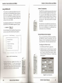
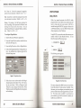
Using KINSTALL.EXE
You must have an application installed on your computer before you can install the Kelvin 64 software
drivers for that application. KINSTALL.EXEis an
easy-to-use, menu driven installation program that
allows you to automatically install the Kelvin 64
software drivers and utilities.
l
....D
The Orchid
icon will only
appear on
workstations
that have a
Kelvin 64
installed.
Insert the Kelvin 64disk into your A: drive and invoke
the KINSTALL.EXEinstallation program by typing:
A: \KINSTALL
l
Enter ~
,
From the Display Driver Installation Program menu,
press any key, and the following menu appears:
The KINSTALLinstallation program offers standard
and network installation options for Windows drivers. If you are using Windows on the Novell (or
compatible) network, install the Kelvin 64Windows
drivers to the Shared Windows directory on the
network server. Select the Network Server Installation option.
Once the drivers are installed on the network server,
the Orchid icon appears in the Windows Control
Panel on the workstation(s), for individual driver
customization on each workstation.
Microsoft Windows Driver Installation
Orchid Technology
Once you select the Microsoft Windows installation,
the KINSTALL program automatically copies the
Windows 3.1 driver and the Kelvin 64 Setup utility
to your hard drive. Follow the instructions below:
Microsoft Windows
Lotus 1-2-3
Computer Aided Design
To configure the Windows driver:
Word Processing
1. Start the MicrosoftWindows application.
Technical Support
U t-tlve
.J=Select
Esc=PreviousMenu
Fl=Help
F3=Atort
r-.
&
FIgure 2.1: KINSTALL Main Menu Screen
Main Menu, highlight the driver to be
111'111111\'d hy using the <i -1-> arrow keys and press
l' N 1'1il{ • III select. Proceed through the installation
IIi 1111111'1ll\'d
by the program. Repeat this process for
Ilil drlvl'I'H vuu wish to use with the Kelvin 64.
FlI\llI
Ilw
For
assistance
during the
installation
process,
Ki'STJ!J..LEXE
provides online help by
selecting
the F1 key
at any time.
To see
information
about the
configuration
of your Kelvin
64, click on
the control
menu box in
the upper-left
comer of the
dialog box,
then select
the About
option.
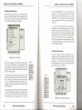
2. Double-click on the Control Panel icon (usually
located in the Main group on the Windows desktop). From the Control Panel window, doubleclick on the Kelvin 64 Setup icon. The following
menu appears:
I~)
Irj~i!is.-;.n
Figure 2.2: Kelvin 64 Setup Menu
20
Kelvin 64 User's Manual
Kelvin 64 User's Manual
21
II
Section
2: Device Drivers and Utilities
This easy-to-use setup menu allows you to configure
your Windows video driver by choosing the resolution, colors, font cache and text font size. The menu
also includes the Big Picture feature, which provides
Virtual Screen and Magnification options for your
display.
3. Make your desired selections and click on the
Change button to restart Windows. You are now
ready to use the graphics capabilities of Kelvin 64.
Use this utility now and for any future changes to the
Kelvin 64 video display.
Section 2: Device Drivers and Utilities
If the Font
Cache
selection is
grayed out,
!!themode
selected does
not support
font caching.
2. Click on the What's This? choice. A definition of
your menu selection is displayed.
Figure 2.4: Inquiry Option Defined
For details on using the other KINST ALL menu options,
press the Fllcey at any time for on-line help.
Center Window Option
This option centers the Kelvin 64Setup menu. Selecting Center Window places the menu screen in the
center of the screen every time it is accessed. To use
this option, follow the steps below:
Menu Features
Inquiry Option
You can request information about the menu options
on the Kelvin 64Setup menu. Each option has a dropdown list box to show available choices.
1. Click on the Control-menu box in the upper-left
corner of the dialog box (see Figure 2.2). The
following menu appears:
For example, to request information about the Desktop Resolution, follow the steps below:
1. Using your right mouse button, click on the arrow
at the right of the box. A drop-down list appears.
Figure 2.5: Center Window Option
2. Click on the Center Window box, then click on
Change to restart windows.
Figure 2.3: Inquiry Option
22
Kelvin 64 User's Manual
Kelvin 64 User's Manual
23
Section 2: Device Drivers and Utilities
Section 2: Device Drivers and Utilities
Big Picture Feature
Screen Saver Option
Use this option for power savings on your Green PC
monitor while your monitor is inactive. When you
use this option with a Green PC monitor or other type
of monitor, you will see a blank screen.
To configure the screen saver:
1. Double-click on the Control Panel icon. From the
Control Panel window, double-click on the Desktop icon.
2. From the Screen Saver box, click on the arrow at
the right of the box. A drop-down list appears.
Click on the Kelvin 64 Green PC selection.
3. Click on the Test button to test the screen saver.
Click on Cancel to stop the test.
4. Click on the Setup button and the following screen
appears:
For more
information
on the Green
PC feature,
see
AppendixB.
The Big Picture feature of the Kelvin 64 Setup utility
offers two options: Virtual Screen and Magnification.
Virtual Screen
You can use the Virtual Screen option to create a
larger desktop workspace (see Figure 2.2). With
Virtual Screen, your mouse movement automatically
pans the desktop to give you access to any part of
your document or window without resizing or using
scroll bars.
It is an ideal solution for spreadsheet or desktop
applications. A large area of display can be panned
and viewed by simply moving your mouse. Virtual
Screen doubles your workspace by transforming your
standard VGA monitor into a virtual display with
pixel resolution up to l024x768.
To configure Virtual Screen:
1. From the Control Panel window, double-click on
the Kelvin 64 Setup icon. The menu in Figure 2.2
appears.
2. From the Big Picture box, click on Virtual Screen.
3. Click on your choice of resolution, colors, font
cache and text font size. Click on Change to reset
Windows so your changes will take effect.
Figure 2.6: Screen Saver Option
5. Configure the screen saver and select a power
saver mode for your Green PC monitor.
24
Kelvin 64 User's Manual
Magnification
The Magnification option allows you to enlarge a
portion of your document to its maximum size. This
is ideal when you need a closer view of your drawing.
The Magnification Key Configuration selection allows you to configure a Hot-Key sequence to activate
the following options:
Kelvin 64 User's Manual
25
Section 2: Device Drivers and Utilities
Section 2: Device Drivers and Utilities
In = Zoom In. Use the In command to magnify a
portion of your document. (Default is <ALT> + <1»
UTILITY SOFTWARE
Using KSCAN
Out = Zoom Out. Use the Out command to see all of
your document at one time. (Default is <ALT> + <2»
With a few simple keystrokes, the KSCAN utility
program allows you to define your monitor type and
select a video mode for your monitor. KSCAN is
installed using the KINSTALLprogram. Because it is
a DOS-based utility, do not run KSCAN from inside
other programs, such as Windows.
Freeze = No panning. Use the Freeze command to
turn off panning, which prevents the Window from
moving even if you move your mouse. You can
unfreeze the Window by using the Hot Key combination. (Default is <ALT> + <3»
To configure Magnification:
Using KSCAN, you can also center the screen on your
monitor while in Video Modes Preview. To run
KSCAN from the DOS prompt, type:
1. Start the Microsoft Windows application.
2. From the Control Panel window, double-click on
3. From the Big Picture box, click on Magnification.
4. Click on the Magnifica tion Key Configuration option. An additional set of options appear in the
Kelvin 64 Setup menu.
Figure 2.7: Magnification Option
5. Select a key to use to activate each of the Magnification features (a Hot-Key). Press <ALT> plus a
key of your choice. Click on Change to reset
Windows so your changes will take effect. When
Windows restarts, the Magnification icon appears
on the desktop.
26
Kelvin 64 User's Manual
CD KELVIN
C : \
the Kelvin 64 Setup icon.
( Enter
f-' ,
then
--D
/fyoudonot
have a mouse
driver loaded
in DOS, orit
youpreter
using the
keyboard, use ~
the TAB key
to move
around the
menus.
c. \KSCAN
( Enter
f-' ,
The following menu appears:
KSCAN Ulilil)' PJ'or:;I'um
IC!EIp:.n: 1101>I••••
I[VldeD'lIodes-,
ICAIIout-
ICHelji·on"\!lduoMDd..
I
make a selection,
I
1
[K.'[vinM
l'BrOS'Vt!':sio'~ f.~o
Icll.olp on i<••• booNl
ICEt1t=1 Ie IIe/p on
I To
Tyj8"
press
1204HI<
Video
j\:1CJIIO/'yI
Mojpe
tile underlined
leiter.
I
Figure 2.8: KSCAN Main Menu
This menu displays the BIOS version of your Kelvin
64 and the amount of video memory installed. From
this menu, you can configure your monitor type and
preview all the video modes supported by your monitor. The video modes available to you depend on
your monitor type and the amount of memory installed on your Kelvin 64.
Kelvin 64 User's Manual
27
Section 2: Device Drivers and Utilities
Section 2: Device Drivers and Utilities
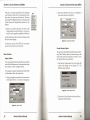
Selecting the Monitor Type
screen is displayed with a set of color blocks and
sample text. The mode number and mode being
tested is displayed at the bottom of the screen. Press
<ENTER> to move through each mode available.
You can abort the test at any time by pressing the
<ESC> key.
Selecting the proper monitor type allows Kelvin 64 to
display the highest quality output supported
with
your monitor.
From the main menu select Monitor
Type, and the following menu appears:
If any of the screens appear distorted, rolling, or
unreadable,
or if the program hangs up, it is likely
that the monitor type you selected is incorrect. Consult your monitor's reference guide before making
another selection. After you ha ve verified your selection, select the OK button to save your setting, or
press the Cancel button to discard the change. Once
you select the OK button, your selection is saved in
the AUTOEXEC.BAT file.
MONITOR SELECTION
o
o
o
o
o
o
o
o
1 8S14
compatible
2 Soper
VGA
3 Extended Super VGA
1. MullifreQuency
5
Extended
6
Super
7
Extended
Mulfifrequency
Multifrequency
Super
Multifrequency
34
r-slcn
jVideo
0.138
Memory
Advanced
Ir~.1
Advanced
II:D Ir~ I I["IlU
You can customize the monitor timings for your
monitor to achieve the highest vertical refresh rates
available. From the Monitor Type Setup menu, select
Advanced.
Once you select Advanced,
the gray
button will show Set Advanced. Select Set Advanced
and the following menu appears:
Figure 2.9: Monitor Type Setup
This screen displays a list of different monitor types.
Use a mouse or TAB key on your keyboard to select
your monitor type. NOTE: To use a mouse, the mouse
driver must be installed in DOS before running the
KSCAN utility program.
The resolutions and refresh rates available for your
monitor are listed in the box below the monitor selections. Selecting the Advanced monitor selection allows you to customize the monitor timings for your
monitor, more on this option in the Advanced Monitor Setup Section.
After making your selection, select the Verify button
to check that the setting selected is compatible with
your monitor. The Verify option will test each video
mode available for your monitor type.
Each test
28
Kelvin 64 User's Manual
If you are not
sure what
type of
monitor you
have, consult
your
monitor's
reference
guide.
Monitor Setup
...-D
Setting the
incorrect
values may
damage your
monitor.
Consult your
monitor's
reference
guide forthe
vertical
refresh rstee
available.
3.
rsiQn
Video
6.6e
Memory
Figure 2.10: Advanced Monitor Type Setup
Kelvin 64 User's Manual
29
\:,,1
Section 2: Device Drivers and Utilities
Appendix A: Technical Help and Information
rl,I,l
II'
,I
Selecting the Set Advanced button displays a dialog
box with drop-down menus for each available resolution. Select the desired vertical refresh rate for each
resolution. After making your selections, press the
Verify button to check that the setting selected is
compatible with your monitor. The Verify option will
test each video mode available for your monitor type.
Appendix
A
TECHNICAL HELP
Orchid Technology is known for its responsiveness
to its customers. This section gives you helpful hints
for troubleshooting Kelvin 64.
Troubleshooting
the Kelvin 64
The following information will help you diagnose
problems you may have with the Kelvin 64.
Video Modes
The Video Modes option displays all video modes
supported, based on your monitor type and amount of
video memory installed on Kelvin 64. From the main
menu, select Video Modes. From the Video Modes
screen, select Preview.
To see what a mode will look like on your monitor,
highlight the mode, then select Preview. There are
several test screens for each mode selected. Press
<ENTER>to move through each test screen. You can
abort the test at any time by pressing the <ESe> key.
Following these simple steps serves a two-fold purpose:
You may be able to fix your problem and avoid
having to contact the Orchid Technology Technical Support Department,
or
if these steps do not help you solve your problem, the results will most certainly give you a
better handle on what to tell Technical Support
once you do contact them.
The information provided here is in symptom/response form. That is, a symptom is given, and a check
point response is provided for you.
Symptom 1
The computer does not power-up or respond when
powered on. The screen is completely blank. There
is no familiar boot up (POST test) beep.
Check
1. Is the Kelvin 64 properly installed in the slot? Is
the edge connector inserted all the way into the
expansion slot? Is the Kelvin 64 properly aligned
with the motherboard's backplane?
2. Is there another display adapter in your syst (.!111? II
it is an on-board video display adapter, mn k(' 14111'1)
30
Kelvin 64 User's Manual
Kelvin 64 User's Manual
37
Appendix A: Technical Help and Information
it is disabled. If the video display adapter is other
than a standard MDA video adapter, remove it
from the system.
3. Is the computer set up correctly for the Kelvin 64?
Refer to your computer's reference manual for
information on setting up your computer.
4. Are your computer and monitor plugged in? Check
the power cables to your computer and monitor.
Symptom 2
The computer gives an error of 1 long beep and 2
short beeps at power up.
Check
Symptom 4
The display loses synchronization
a graphics program.
once it gets into
Check
1. Is the vertical hold on your monitor properly set?
Is your software properly installed for your current application? CheckSection2for DeviceDriver
information.
3. Is your monitor able to display the graphics mode
you are using? Double check your monitor specifications to determine if you are operating in a
graphics mode that your monitor simply cannot
handle.
1. Take a look at the check points for symptom 1,
steps 1 through 4.
4. Are you using the correct vertical refresh rate for
your monitor? Double check your monitor specifications for the refresh rates supported.
Symptom 3
Symptom 5
The computer seems to boot up properly but there
is no display.
The Kelvin 64 works well in another brand computer, but not at all in mine.
Check
Check
1. Is your monitor plugged in? Check the power
cable to your monitor.
1. Take a look at the check points for symptom 1,
steps 1 through 4. It is a pretty good guess that the
problem is not the Kelvin 64 if it is working properly in another system.
2. Is your monitor cable fastened securely and properly? Check both the connection at the monitor
and at the Kelvin 64 card.
3. Is your monitor cable the correct kind for the
Kelvin 64?Check Section 1 for the proper pin- out
information to determine if your cable is correct.
4. Is there another display adapter in your system? If
it is an on-board video display adapter, make sure
it is disabled. If the video display adapter is other
than a standard MDA video adapter, remove it
from the system.
32
Appendix A: Technical Help and Information
Kelvin 64 User's Manual
Symptom 6
The Orchid icon does not appear in the Windows
Control Panel.
Check
1. Check to make sure that you installed the Kelvin
64 Windows drivers into the correct directory.
2. Memory managers can prevent icons from appearing. See Appendix A for details about using
memory managers.
Kelvin 64 User's Manual
33
Appendix
A: Technical Help and Information
TECHNICAL INFORMATION
This section covers the specifications and features of
the Kelvin 64, including information on upgrading
the memory.
Appendix A: Technical Help and Information
Additional Features:
Supports
75Hz Vertical Scan Refresh Rate
1024 x 768 x 256 colors - Interlaced and NonInterlaced
Kelvin 64 Technical Specifications
Configuration
Kelvin 64 -
640 x 480 x 16.8 million colors
1024KB
2048KB
800 x 600 x 16.8 million colors (with 2MB DRAM)
1280 x 1024 x 256 colors - Non-Interlaced (with
2MB DRAM)
Video Chipset:
Cirrus Logic 5434
Upgrade RAM Chips:
256KBx 16, 70 nanoseconds or faster DRAM
Computers Supported:
486 and compatibles (with VL-Bus connector)
Pentium-based systems
Memory Address Segments:
RAM: AOOO-BFFF
ROM: COOO-C7FF
110
Address: 3BO-3DF(IBM standard)
Temperature:
Operating: from 0 to 40 degrees C
Storage: from -25 to 90 degrees C
Interface Speed
Up to 50MHz
BIOS:
8-bit
Bus Connector:
32-bit - Kelvin 64/VLB
32-bit - Kelvin 64/PCI
16-bit - Kelvin 64/ISA
Humidity:
Operating: from 15% to 90%
Storage: from 0% to 90%
Card Size:
9.34"x 3.34"
7" x 3.75"
7.25"x 3.75"
Output Connectors:
15-pin D-Shell VGA
Feature Connector (VESA bi-directional)
34
Kelvin 64 User's Manual
Kelvin 64 User's Manual
35
Appendix
Appendix A: Technical Help and Information
A: Technical Help and Information
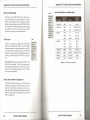
Kelvin 64 Resolutions and Refresh Rates
Memory Address Setting
Please be
sure your
monitor
,supports
Kelvin 64 uses the AOOO-C7FFmemory address segment. Some memory manager programs may try to
use this address segment. If you encounter a conflict,
add an exclusion statement in your CONFIG.5YS file,
to exclude the Kelvin 64 address segment from being
used. Refer to your software program user's manual
for details on using an exclusion statement.
I your
I, selected
.,.,.(~
VESA Support
mode and
frequency
(refer to your
monitor's
reference
guide) .
Resolution
Maximum
Memory
Colors
Vertical
Refresh
1280x1024
1MB
16
43.5,60
1024x768
1MB
16
43.5,60,70,72,75
1MB
256
43.5,60,70,72,75
1MB
16
60,72,75
1MB
256
60,72,75
1MB
65,536
60,72,75
1MB
16
60,75
1MB
256
60,75
800x600
640x480
Kelvin 64 is designed to support the VESA BIOS
Extension (VBE) through its BIOS. The VESA BIOS
Extension standard is a separate standard from VESA
Local BUS (VLB). Extended modes can be selected
through the VESA option in the application you are
running. The BIOS supports the VESA 1.2 specification.
Kelvin 64IVLBis designed to support the VESA Local
Bus (VL-Bus) standard. The local bus design provides 32-bit data transfer between the video card and
the CPU for incredibly fast graphics, and is VL-Bus
1.0 backward compatible.
All Kelvin 64
models
support the
VESA BIOS
Extension
(VBE)
regardless
of their bus
interface
type.
1MB
65,536
60,75
1280x1024
2MB
256
43.5,60
1024x768
2MB
65,536
43.5,60,70,72,75
800x600
2MB
16.8 million
56,60
640x480
2MB
16.8 million
60,75
Table A.1: Resolutionsand refreshrates
How to obtain the Memory Upgrade Kit
If you have 1MB of memory on your Kelvin 64 and
would like to upgrade to 2MB of memory, call our
Customer Service staff to purchase a memory upgrade kit. Orchid Technology's telephone number is
on the Technical Help and Warranty Card enclosed
with your Kelvin 64.
36
Kelvin 64 User's Manual
Kelvin 64 User's Manual
37
Appendix
A: Technical Help and Information
Appendix
Feature Connector Pin Outs (VESA Standard)
Appendix
The VESAstandard Feature Connector (or Auxiliary
Video Connector as it is sometimes called) is located
at the top of the Kelvin 64 (see Figures 1.1, 1.2 or 1.3).
B
The feature connector permits third party add-on
accessories to both share signals and share control of
the VGA circuitry. The following table lists the
feature connector's pin-out information:
B - Green PC
GREEN PC
Orchid stays on the cutting edge of technology while
maintaining compatibility. With the Kelvin 64, we
took a power saving approach by incorporating the
Green PC technology. The following information
details the Green PC technology.
Green PC Feature
Kelvin 64 Feature tonnector
Pin
Function
Pin
Y1 Pixel Data 0
Function
Y8 Pixel Data 7
Pin-Outs
Pin
Function
Pin
Function
Z2
Ground
Z9
Ground
Y2 Pixel Data 1 Y9
Pixel Clock
Z3
Ground
Z10
Ground
Y3 Pixel Data 2 Y10
Blanking
Z4
(See Note 1)
Z11
Ground
Y4 Pixel Data 3 Y11
Hor. Sync
Z5
(See Note 2)
Z12. No Connect
Y5 Pixel Data 4 Y12 Vert. Sync
Z6
(See Note 3)
Z13 No Pin (Key
Y6 Pixel Data 5 Y13
Ground
Z7
No Connect
Y7 Pixel Data 6
Ground
Z8
Ground
Z1
Table A.2:
VESA Feature Connector Pin-Outs
NOTES:
(1) Low Enable External Pixel Data Input to the
motherboard DAC
(2) Low Enable External Sync and Blanking Inputs
to the motherboard DAC
(3) Low Enable External Pixel Clock Input to the
motherboard DAC
The Green PC feature allows a computer system to be
energy efficient. The most common method to save
energy was developed by VESA and called the Display Power Management Specification (DPMS). On
computer desktop systems, monitors usually consume over 50% of the overall power used. Most
monitors consume between 130-200watts, even when
idling.
Using a Green PC monitor and a Kelvin 64in conjunction, you can lower the power consumption to 30
watts when the monitor is idle. This power management feature is required by the EPA's Energy Star
Program and is also required by all U.S. government
agencies.
A Green PC monitor and your Kelvin 64 can be
placed into one of four states: On, Standby, Suspend
or Off. Here is an overview of the DPMS signaling
method:
Monitor
State
Power
Savings
Recovery
Time
On
Standby
Suspend
Off
None
Minimal
Substantial
Maximum
N/A
Short
Longer
System-dependent
The power management technology of this feature
implement the VESA Display Power Management
38
Kelvin 64 User's Manual
Kelvin 64 User's Manual
39
Appendix
8 - Green PC
(DPMS) proposal, the U. S. Government Environmental Protection Agency "Energy Star" and the European "Nutek" standards. The Green PC Power
Management feature makes Kelvin 64 a complete
cost-effective solution for the energy conscious.
FCC
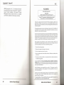
FCC NOTICE
FCC# DDS7EF1093-93-KVL
*
Kelvin 64NLB
Certified compliant with FCC Class B limits, part 15
To meet FCC requirements, shielded cables are required
to connect the unit to a Class B certified device
'This device complies with Part 15 of the FCC Rules. Operation is subject to the
following two conditions: (1) this device may not cause harmful interference, and (2)
this device must accept any interference received, including interference that may cause
undesired operation."
This equipment generates and uses radio frequency energy and, if not installed and
used properly in strict accordance with the manufacturer's instructions, may cause
interference to radio or television reception.
This device has been tested and found to comply with the limits for a Class Bcomputing
device in accordance with the specifications in Subpart J of Part 15 of FCC Rules, which
are designed to provide reasonable protection against such interference in a residential
installation. Only equipment (computer input/ output devices, terminals, printers, etc.)
certified to comply with the Class B limits may be attached to this product.
If this equipment causes interference to radio or television reception, which can be
determined by turning the equipment off and on, the user is encouraged to try and
correct the interference by one or more of the following measures:
1. Reorient the receiving antenna.
2. Relocate the computer with respect to the receiver.
3. Move the computer away from the receiver.
4. Plug the computer into an outlet which resides on a different circuit breaker than
the receiver.
5. If necessary, consult your dealer, or an experienced radio or television technician
for additional suggestions.
You may find the booklet How To Identify and Resolve Radio-TV Interference
Problems helpful. It was prepared by the Federal Communications Commission and
is available from the U.S. Government Printing Office, Washington, DC 20402.Refer to
stock number: 004-000-00345-4.
Orchid Technology is not responsible for any radio or TV interference caused by
unauthorized modifications to this equipment. It is the responsibility of the user to
correct such interference.
Operation with non-certified equipment is likely to result in interference to radio and
TV reception. The user must use shielded interface cables in order to maintain the
product within FCC compliance .
• For Kelvin 64NLB only. For Kelvin 641PCI the FCC number is DDS7EFI193-93-PCI.
Kelvin 6411SAthe FCC number is DDS7EF0294-94-ISA.
40
Kelvin 64 User's Manual
Kelvin 64 User's Manual
For
41
Index
Index
INDEX
H
15 pin video connector - 17
Help
Tips to use - 31
High Resolution Drivers
See Device Drivers
Adding Memory - 15
AutoCAD-20
Drivers Installation
See KINSTALL
Installation
Installing the Kelvin 64 -16
Preparing your Computer - 15
Preparing your Kelvin 64 - 15
A
B
Big Picture Feature - 25
K
Kelvin 64 software setup - 21
KINSTALL installation program - 20
KSCAN utility software - 27
D
Device Drivers - 20
See also Windows 3.1, AutoCAD, Lotus 1-2-3,
WordPerfect
L
Lotus 1-2-32.x - 38
Drivers Installation
See KINSTALL
F
Kelvin 64 Video Setup - 21
Feature Connector Pin-Outs - 38
G
Green PC -39
42
Kelvin 64 User's Manual
M
Magnification option - 43
Menu features - 22
Microsoft Windows Driver Installation - 20, 21
Monitor Cable Pin-out Information -17
Monitor Vertical Refresh Rates - 37
Kelvin 64 User's Manual
43
Index
N
Network Considerations - 21
T
Technical Help - 31
Technical Information - 34
Troubleshooting - 31
u
Utility Program
KSCAN -27
v
Vertical Refresh Rates - 37
VESA Support
VESA BIOS Extension (VBE)- 36
VESA Local Bus (VL-Bus)- 36
VESA Feature Connector Pin-Outs - 38
Video Display Setup - 21
Video Graphics Modes Table - 37
Virtual Screen option - 25
w
Windows
Drivers Installation
See KINSTALL
WordPerfect
Drivers Installation
See KINSTALL
44
Kelvin 64 User's Manual
-,0
390-
::lQ.
£+~
OJ
e:
~
n
3" :J
a:
om
"'c
'"
.
(3
CU
;A-
c
:I
Z
.z:
..::
~
s:: 0
-,
n
:J
ac --
(1)
(1)
Q..
'"
--I
rv (1)
.:J n
:J
G)
(1)
::l
0
0
3!!.I,<
::l
'<
G)
3
~