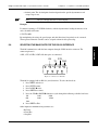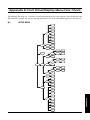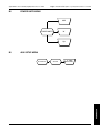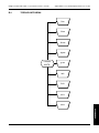
1
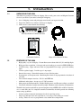
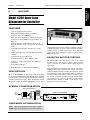
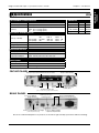
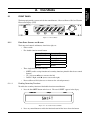
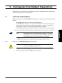
MODEL 6200 Open Loop Dynamometer Controller User’s Manual Purchase Record Please record all model numbers and serial numbers of your Magtrol equipment, along with the general purchase information. The model number and serial number can be found on either a silver identification plate or white label affixed to each unit. Refer to these numbers whenever you communicate with a Magtrol representative about this equipment. Model Number: _____________________________ Serial Number: _____________________________ Purchase Date: _____________________________ Purchased From: _____________________________ While every precaution has been exercised in the compilation of this document to ensure the accuracy of its contents, Magtrol, Inc. assumes no responsibility for errors or omissions. Additionally, no liability is assumed for any damages that may result from the use of the information contained within this publication. Copyright Copyright ©2002- 2014 Magtrol, Inc. All rights reserved. Copying or reproduction of all or any part of the contents of this manual without the express permission of Magtrol is strictly prohibited. Trademarks LabVIEW™ is a trademark of National Instruments Corporation. Microsoft® is a registered trademark of Microsoft Corporation. National Instruments™ is a trademark of National Instruments Corporation. Windows® is a registered trademark of Microsoft Corporation. 1st Edition rev. A – March 2014 Safety Precautions 1. Make sure that all Magtrol dynamometers and electronic products are earth-grounded, to ensure personal safety and proper operation. 2. Check line voltage before operating the 6200. 3. Make sure that dynamometers and motors under test are equipped with appropriate safety guards. iii Revisions To This Manual The contents of this manual are subject to change without prior notice. Should revisions be necessary, updates to all Magtrol User’s Manuals can be found at Magtrol’s web site at www.magtrol.com/support/manuals.htm. Please compare the date of this manual with the revision date on the web site, then refer to the manual’s Table of Revisions for any changes/updates that have been made since this edition. Revision Date 1st Edition rev. A – March 2014 Table of Revisions Date Edition Change Section(s) 03/03/14 1st Edition - rev. A Torque Offset and Gain procedure updated. 6.3.2 03/03/14 1st Edition - rev. A Basic Calibration Process updated. 6.3 03/03/14 1st Edition - rev. A Accessory Torque/Speed Output diagram updated. 2.2.1 iv Table of Contents Safety Precautions........................................................................................................................ iii Revisions To This Manual............................................................................................................... iv Revision Date.................................................................................................................................................................iv Table of Revisions......................................................................................................................................................iv Preface................................................................................................................................................ vii Purpose of This Manual.........................................................................................................................................vii Who Should Use This Manual..............................................................................................................................vii Manual Organization.............................................................................................................................................vii Conventions Used in This Manual.................................................................................................................. viii 1. Introduction................................................................................................................................. 9 1.1 Unpacking Your 6200............................................................................................................................................. 9 1.2 Features of the 6200.............................................................................................................................................. 9 1.3 Data Sheet................................................................................................................................................................ 10 2. Controls........................................................................................................................................ 12 2.1 Front Panel............................................................................................................................................................. 12 2.1.1 Front Panel Controls and Buttons................................................................................................................... 12 2.1.2How to Use Front Panel Controls and Buttons............................................................................................... 13 2.2rear panel............................................................................................................................................................... 14 2.2.1 Rear Panel Functions....................................................................................................................................... 14 2.3 Vacuum Fluorescent Display (VFD)............................................................................................................ 16 2.3.1 Contrast Settings............................................................................................................................................. 16 2.3.2 Displaying Desired Information...................................................................................................................... 16 3. Installation.................................................................................................................................... 9 3.1 Powering up the 6200............................................................................................................................................ 9 3.1.1 Setting Unit for Line Voltage............................................................................................................................ 9 3.1.2Hardware Connection...................................................................................................................................... 10 3.1.3Self-Test.......................................................................................................................................................... 10 3.2 Basic Test Setup.................................................................................................................................................... 10 4. Manually Controlled Operation........................................................................................ 11 4.1setting desired operating parameters.................................................................................................. 11 4.1.1 Set Power Display to Desired Units (Watts, Hp or Aux.)............................................................................... 11 4.1.2 Set Display to Desired Torque Units............................................................................................................... 11 4.1.3 Set up System Parameters............................................................................................................................... 11 4.1.4 Set Up Pass/Fail Parameters............................................................................................................................ 11 4.1.5 Set Up I/O Parameters..................................................................................................................................... 12 4.2setting dynamometer load.......................................................................................................................... 12 4.3using internal memory................................................................................................................................... 13 4.3.1 Storing Data Points......................................................................................................................................... 13 4.3.2 Recalling Data Points...................................................................................................................................... 13 4.3.3 Exiting the Memory Mode.............................................................................................................................. 13 4.3.4 Clearing the Memory...................................................................................................................................... 13 5. Computer Controlled Operation....................................................................................... 14 5.1about the gpib interface................................................................................................................................ 14 v Table of Contents Magtrol Model 6200 Open Loop Dynamometer Controller 5.1.1 Installing the GPIB (IEEE-488) Connector Cable.......................................................................................... 14 5.1.2 Changing the GPIB Primary Address............................................................................................................. 15 5.2checking the 6200-to-pc connection......................................................................................................... 15 5.3programming......................................................................................................................................................... 16 5.4 6200 command set................................................................................................................................................. 16 5.4.1 Command Set for 6200................................................................................................................................... 16 5.5 ACQUIRING SPEED-TORQUE DATA....................................................................................................................... 18 5.6selecting the baud rate for the rs-232 interface............................................................................ 19 6. Calibration................................................................................................................................... 21 6.1 Closed-Box Calibration.................................................................................................................................. 21 6.2 Calibration Schedule....................................................................................................................................... 21 6.3Basic Calibration Process.............................................................................................................................. 21 6.3.1 Initial Calibration Procedure........................................................................................................................... 21 6.3.2 Torque Offset and Gain................................................................................................................................... 22 6.3.3 Accessory Torque Offset and Gain................................................................................................................. 23 6.3.4 Auxiliary Input Offset and Gain..................................................................................................................... 23 6.4 Alternate Calibration Procedure............................................................................................................ 23 7. Troubleshooting........................................................................................................................ 26 Appendix A: LabVIEW Programming Examples...................................................................... 27 A.1Simple Read............................................................................................................................................................. 27 A.2Current Stabilized............................................................................................................................................. 28 Appendix B: Front Panel/Display Menu Flow Charts........................................................ 29 B.1sETUP Menu.............................................................................................................................................................. 29 B.2 Power Units Menu................................................................................................................................................ 30 B.3 Aux Setup Menu..................................................................................................................................................... 30 B.4 Torque Units Menu............................................................................................................................................. 31 Appendix C: Schematics................................................................................................................. 32 C.1encoder/Switch Board..................................................................................................................................... 32 C.2 Power Supply.......................................................................................................................................................... 32 C.3 DSP & Memory......................................................................................................................................................... 33 C.4 Analog I/O................................................................................................................................................................ 34 Service Information....................................................................................................................... 35 Returning Magtrol equipment for Repair and/or Calibration....................................................... 35 Returning Equipment to Magtrol, Inc. (United States)................................................................................................. 35 Returning Equipment to Magtrol SA (Switzerland)...................................................................................................... 35 vi Magtrol Model 6200 Open Loop Dynamometer Controller Table of Contents Table of Figures 2. Controls........................................................................................................................................ 12 Figure 2–1 Figure 2–2 Figure 2–3 Figure 2–4 Figure 2–5 Figure 2–6 Figure 2–7 Figure 2–8 Front Panel ................................................................................................................................................ 12 Secondary Function Menu......................................................................................................................... 12 Rear Panel.................................................................................................................................................. 14 Dynamometer Brake Output...................................................................................................................... 14 Accessory Torque-Speed Output................................................................................................................ 14 Dynamometer/TSC1 Connector................................................................................................................. 15 RS-232C Interface...................................................................................................................................... 15 GPIB/IEEE-488 Interface.......................................................................................................................... 15 3. Installation.................................................................................................................................... 9 Figure 3–1 Cover for Voltage Selector, Fuses................................................................................................................ 9 5. Computer Controlled Operation....................................................................................... 14 Figure 5–1 GPIB (IEEE-488) Interface........................................................................................................................ 15 Figure 5–2 Connector Pin-Out..................................................................................................................................... 19 6. Calibration................................................................................................................................... 21 Figure 6–1 Alternative Calibration............................................................................................................................... 24 vii Preface Purpose of This Manual This manual contains all the information required for the installation and general use of the Model 6200 Open Loop Dynamometer Controller. To ensure proper use of the instrument, please read this manual thoroughly before operating it. Keep the manual in a safe place for quick reference whenever a question arises. Who Should Use This Manual This manual is intended for bench test operators who are going to use the Model 6200 Dynamometer Controller in conjunction with any Magtrol Hysteresis Dynamometer or auxiliary instrumentation. Manual Organization This section gives an overview of the structure of the manual and the information contained within it. Some information has been deliberately repeated in different sections of the document to minimize cross-referencing and to facilitate understanding through reiteration. The structure of the manual is as follows: Chapter 1: Introduction - Contains the technical data sheet for the 6200 Dynamometer Controller, which describes the unit and provides its technical characteristics. Chapter 2: CONTROLS - Description of the elements located on the front and rear panels of the unit. Chapter 3: Installation - Provides setup options available with the 6200 Dynamometer Controller. Illustrates and outlines the hardware connection setup and software configurations for each option. Chapter 4: MANUALLY CONTROLLED OPERATION - How to run a test when the 6200 is used as a stand-alone unit. Includes information on setting power and torque units, torque and speed control and open loop control. Chapter 5: COMPUTER CONTROLLED OPERATION - How to run a test when the 6200 is used with a PC. Includes information on GPIB Interface, RS-232 Interface, data format, programming and command set. Chapter 6: Calibration - Provides recommended calibration schedules along with stepby-step instructions for the calibration procedure. Chapter 7: Troubleshooting - Solutions to common problems encountered during setup and testing. Appendix A: LabVIEW™ Programming Examples - Magtrol’s comprehensive motortest software programs, made specifically to compliment the 6200 Dynamometer Controller. Appendix B: Front Panel/Display Menu Flow Charts - A visual display of various setup procedures. vii Preface Magtrol Model 6200 Open Loop Dynamometer Controller Appendix C: Schematics - For Encoder/Switch Board, Power Supply, DSP & Memory and Analog I/O. Conventions Used in This Manual The following symbols and type styles may be used in this manual to highlight certain parts of the text: Note: This is intended to draw the operator’s attention to complementary information or advice relating to the subject being treated. It introduces information enabling the correct and optimal functioning of the product to be obtained. Caution:This is used to draw the operator’s attention to information, directives, procedures, etc. which, if ignored, may result in damage being caused to the material being used. The associated text describes the necessary precautions to take and the consequences that may arise if the precautions are ignored. WARNING! This introduces directives, procedures, precautionary measures, etc. which must be executed or followed with the utmost care and attention, otherwise the personal safety of the operator or third party may be put at risk. The reader must absolutely take note of the accompanying text, and act upon it, before proceeding further. viii Introduction 1.1Unpacking Your 6200 Your 6200 was packaged carefully for shipping. Please notify your carrier and Magtrol Customer Service if you believe your unit was damaged in shipping. 1. Save all shipping cartons and packaging material until you inspect the 6200. 2. Inspect the 6200 for any evidence of damage in shipping. 3. Make sure the carton contains the following: MODEL 6200 POWER/AUX CONTROLLER/DISPLAY TORQUE SPEED DECREASE POWER POWER UNITS TORQUE UNITS AUX SETUP CLR MENU SETUP BRAKE ON/OFF TORQUE SET DISPLAY STORE RECALL INCREASE SHIFT UP DOWN 6200 Dynamometer Controller/Readout Line cord Calibration Certificate Magtrol User Manual CD-Rom 1.2Features of the 6200 • • • • • • • • • • High quality, easy to read display - Vacuum fluorescent readout with 0.36” (9.1 mm) high digits. High-speed data acquisition - 120 torque and speed readings per second via IEEE (GPIB) bus. Pass/Fail testing - Upper and lower limits are programmable for torque, speed, and auxiliary input. Current regulated supply - Provides up to 1 amp output. Internal data storage - Nonvolatile memory of up to 100 data points. Dynamometer overload protection - Maximum power limit can be programmed to shut down if exceeded. Two standard computer interfaces - RS-232 and IEEE-488. Additional analog input - Accepts any ± 5 VDC transducer. Many torque measurement options - Includes English, metric, and SI torque readings as standard. Closed box calibration of torque and auxiliary input - Eliminates need to open box for adjustments. The 6200 is designed to work with any personal computer using an IEEE-488 or an RS-232 interface, or as a stand-alone unit. In a computer-controlled environment, the 6200 provides the following motor testing capabilities: • Current regulated control of dynamometer brake for open-loop testing • Torque (Q) and Speed (N) data acquisition at a rate of up to 120 readings per second. • Saving - Allows user to save programmed values within their configurations. 9 GENERAL INFORMATION 1. Chapter 1 – Introduction M AGTROL Data Sheet 6200 Data Sheet GENERAL INFORMATION 1.3 Magtrol Model 6200 Open Loop Dynamometer Controller Model 6200 Open-Loop Dynamometer Controller Features • • • • • • • • • • • • Open-LoopDynamometerControl Built-inPass/FailMotorTestingCapability Interfaces:RS-232andIEEE-488 HighSpeedDataAcquisition:120torqueandspeed pointspersecondviaIEEEbus(approx.60/sec.via RS-232) HighQuality,Easy-to-ReadVacuumFluorescent Readout:Displaystorque,speed,powerandauxiliary values Current-RegulatedSupply:Providesupto1amp output AdjustableTorqueUnits:English,MetricandSIare standard DynamometerOverloadProtection InternalDataStorage:Upto100datapoints Auxiliary±5VDCAnalogInput:Foradditional transducer ClosedBoxCalibration RackMounting:19"(482.6mm)withhandles andmechanicalpowervaluesofthemotorundertest.Inplace ofmechanicalpower,itcanalsodisplayauxiliarytransducer readings via the ±5VDC analog input. These displayed valuescanbestoredinternallyoroutputviatheRS-232or IEEE-488interface. pass/Fail motor testing The Model 6200 comes with an easy-to-use motor testing Pass/Fail feature. This feature is ideal for quick pass/fail (go/no go) testing in production and incoming inspection applications. Whenthe6200isoperatedinthePass/Failmode,oneofthree readingsisusedasthetestedparameter:torque,speedorthe auxiliarytransducer.Thetwoparametersnotusedaresetwith user-definedupperandloweracceptablelimits.Asthemotor isloadedtothetestedparametervalue(forexample,speed), theothertwoparameters(inthiscase,torqueandtransducer) aremeasured.Testresults(fortheother2parameters)are indicated with a “PASS” or “FAIL”, or the display can be toggledtoshowtheactualvalues. Description Magtrol'sModel6200isanOpen-LoopControllerdesigned forusewithanyMagtrolHysteresisDynamometer.Theunit providesopen-loopcontrolofthedynamometerviaaninternal current-regulatedpowersupply.Withahigh-qualityvacuum fluorescentreadout,theModel6200displaystorque,speed system conFiguration Hysteresis Dynamometer MODEL 6200 CONTROLLER Motor Under Test CAUTION: DOUBLE POLE FUSING 75VA 50/60 Hz BRAKE ACCESSORY TORQUE-SPEED OUTPUT CTRL OUT DYNAMOMETER AUX. INPUT RS–232C GPIB/IEEE–488 EARTH GROUND BRAKE FUSE (5×20mm): UL/CSA 1.25A 250V SB IEC 1A 250V T MAGTROL, INC. BUFFALO, NY FUSE (5×20mm): 120V UL/CSA 800mA 250V SB 240V IEC 315mA 250V T orDering inFormation 6200OpenLoopDynamometerController120VAC 6200AOpenLoopDynamometerController240VAC 10 www.magtrol.com Chapter 1 – Introduction Magtrol Model 6200 Open Loop Dynamometer Controller GENERAL INFORMATION Specifications 6200 MEASUREMENT CHARACTERISTICS MaximumTorque 2000units MaximumSpeed 99,999rpm Speed:0.01%ofreadingfrom10rpmto100,000rpm Accuracy Torque:0.2%ofrange(±2V) Aux:0.1%ofrange(±5V) ELECTRICAL CHARACTERISTICS Brake: UL/CSA 1.25A 250VSB IEC 1.00A 250VT Fuses(5×20mm) Power(120V): UL/CSA 800mA 250VSB Power(240V): IEC 315mA 250VT PowerRequirements 75VA VoltageRequirements 120/240V60/50Hz Max.ComplianceVoltage 45VDC INPUTS AND OUTPUTS AuxiliaryInput ±5VDC Accessory Torque:±2VDC Torque/SpeedOutput Speed:60TTLpulses/rev,50%dutycycle CtrlOut 0–3VDC ENVIRONMENT OperatingTemperature 18ºCto25ºC RelativeHumidity <80% TemperatureCoefficient 0.001%ofrange/°C DIMENSIONS Width 19.0in 483mm Height 3.5in 89mm Depth 12.4in 315mm withhandles 13.8in 351mm Weight 16.37lb 7.42kg Front panel Ready for Rack Mounting Displays Torque, Speed and Mechanical Power Values Internal Memory Set Desired Power Units (W, Hp or AUX) Enables Pass/Fail Testing of Torque, Speed or Auxiliary Input Set Desired Torque Units (oz.in., oz.ft., lb.in., lb.ft., g.cm, kg.cm, Nmm, Ncm, Nm) rear panel Auxiliary Input Accepts ±5 VDC Transducer Connector for Optional Magtrol Readout Connector for Model 5241 Power Supply (for HD-825 Dynamometer only) RS-232 and GPIB/IEEE-488 Interfaces for Connection to PC For Use With Any Magtrol Hysteresis Dynamometer Due to the continual development of our products, we reserve the right to modify specifications without forewarning. magtrol inc 70GardenvilleParkway Buffalo,NewYork14224USA Phone:+17166685555 Fax:+17166688705 magtrol sa 11 CentretechnologiqueMontena 1728Rossens/Fribourg,Switzerland Phone:+41(0)264073000 Fax:+41(0)264073001 Subsidiaries in: GreatBritain Germany•France China•India WorldwideNetwork 00-US 03/06 www.magtrol.com 2.1 Front Panel The front panel provides a power switch, nine control buttons, a Decrease/Increase Dial, and Vacuum Fluorescent Display (VFD) model 6200 POWER/AUX CONTROLLER/DISPLAY TORQUE SPEED DECREASE POWER POWER UNITS TORQUE UNITS AUX SETUP CLR MENU SETUP BRAKE ON/OFF TORQUE SET DISPLAY STORE RECALL INCREASE SHIFT UP DOWN Figure 2–1 Front Panel 2.1.1 Front Panel Controls and Buttons The front panel controls and buttons, from left to right, are: • Power switch • Five double-function control button: • • 2.1.1.1 Primary Function Secondary Function BRAKE ON/OFF POWER UNITS UNITS DISPLAY TORQUE UNITS DISPLAY AUX SETUP STORE CLR MEM RECALL SETUP Three single-function control buttons: • SHIFT (enables saving function and secondary functions printed in blue above control buttons) • UP - Left arrow (moves cursor to the left) • DOWN - Right arrow (moves cursor to the right) Decrease/Increase Dial (decreases or increases the selected parameter) Enabling Secondary Functions To enable the secondary function of the double-function control buttons: 1. Press the blue SHIFT button and release it. The word “SHIFT” appears in the dispay: POWER/AUX TORQUE SPEED Figure 2–2 Secondary Function Menu 2. Press any control button to enable the function shown in blue letters above the button: 12 GENERAL INFORMATION 2. Controls Magtrol Model 6200 Open Loop Dynamometer Controller Chapter 2 – Controls 2.1.2 How to Use Front Panel Controls and Buttons 2.1.2.1 Controls/Single-Function Buttons Button 2.1.2.2 To Use Function POWER Press I to turn power ON. Press O to turn power off. Turns power ON or OFF. SHIFT Press this button and release; then press desired control button. Enables the function written in blue above control button. UP/LEFT Press. Increases magnitude of change when adjusting a numerical value (speed, torque or max. speed). DOWN/RIGHT Press. Decreases magnitude of change when adjusting a numerical value (speed, torque or max. speed). DECREASE/ INCREASE DIAL Turn clockwise or counterclockwise. Increases or decreases the parameter selected. Double-Function Buttons Button To Use Function POWER UNITS Press SHIFT and release; then press this button Sets power display to WATTS, HP or AUX input. BRAKE ON/OFF Press. Toggles brake ON or OFF. TORQUE UNITS Press SHIFT and release; then press this button Enables you to set desired unit of measure. Press UP or DOWN button to see options. Press SHIFT to enable option. UNITS DISPLAY Press. Shows power units, torque units and percent of full scale current output. AUX SETUP Press SHIFT and release; then press this button Enables you to set the scaling of the auxilary input. DISPLAY Press. When in the PASS/FAIL mode, shows actual value of parameter. CLR MEM Press SHIFT and release; then press this button Clears the data memory. Resets next memory location to 0. STORE Press. Stores data into next available memory location. SETUP Press SHIFT and release; then press this button Enables user to select SYSTEM, PASS/FAIL and I/O menus. RECALL Press. Displays memory contents beginning at last stored value. 13 GENERAL INFORMATION POWER UNITS, TORQUE UNITS, AUX SETUP, CLR MEM OR SETUP 3. Press the SHIFT button again to exit the secondary function and return to main menu. Chapter 2 – Controls rear panel The rear panel provides connectors and receptacles for connecting to appropriate equipment. Refer to figures 3, 4 and 5 in this chapter for detailed drawings of the brake CAUTION: DOUBLE POLE FUSING 75VA 50/60 Hz BRAKE ACCESSORY TORQUE-SPEED OUTPUT CTRL OUT AUX. INPUT DYNAMOMETER RS–232C GPIB/IEEE–488 EARTH GROUND BRAKE FUSE (5×20mm): UL/CSA 1.25A 250V SB IEC 1A 250V T 2.2.1 FUSE (5×20mm): 120V UL/CSA 800mA 250V SB 240V IEC 315mA 250V T MAGTROL, INC. BUFFALO, NY Figure 2–3 Rear Panel Rear Panel Functions The rear panel, from left to right, provides the following functions: BRAKE Connect dynamometer brake cable here. Current Regulation +35V Fused Figure 2–4 Dynamometer Brake Output BRAKE Contains brake fuse (5 x 20 mm) (UL/CSA 1.25A250V SB) (IEC1A250V T) CTRL OUT Connect to Model 5241 Power Amplifier when using HD-825 Dynamometer. ACCESSORY Connect accessory output cable here (optional). FUSE TORQUE/ SPEED OUTPUT 7 6 3 5 1 2 4 1. TACH. SIGNAL 2. TORQUE OUTPUT 3. D.P. 4. TORQUE COMMON 5. N/C 6. TACH. COMMON 7. D.P. Figure 2–5 Accessory Torque-Speed Output C aution: For use with Magtrol Readouts only. Connecting another device to this output may cause equipment failure. 14 GENERAL INFORMATION 2.2 Magtrol Model 6200 Open Loop Dynamometer Controller Chapter 2 – Controls Magtrol Model 6200 Open Loop Dynamometer Controller Connect dynamometer signal cable here. 7 6 5 4 3 2 1 14 13 12 11 10 9 8 8. COMMON 9. D.P. 10. TACH. SIGNAL 11. N/C 12. D.P. 13. TORQUE COMMON 14. TORQUE SIGNAL 1. N/C 2. N/C 3. ISOLATED +22 VDC 4. ISOLATED -22 VDC 5. ISOLATED +22 VDC 6. ISOLATED -22 VDC 7. TACH. +5.0 VDC Figure 2–6 Dynamometer/TSC1 Connector AUX INPUT Connect auxiliary instrument signal cable here. RS-232C Use this socket for RS-232 connector cable 5 4 9 3 8 2 7 1 6 1. 2. TX 3. RX 4. 5. GND 6. 7. 8. 9. N/C Figure 2–7 RS-232C Interface GPIB/IEEE-488 Use this socket for GPIB cable (meets IEEE-488 specifications). 12 11 10 9 8 7 6 5 4 3 2 1 24 23 22 21 20 19 18 17 16 15 14 13 1. D1 2. D2 3. D3 4. D4 5. E01 6. DAV 7. NRFD 8. NDAC 9. IFC 10. SRQ 11. ATN 12. SHIELD 13. D5 14. D6 15. D7 16. D8 17. REN 18. DAV-COM 19. NRFD-COM 20. NDAC-COM 21. IFC-COM 22. SRQ-COM 23. ATN-COM 24. SIGNAL GROUND Figure 2–8 GPIB/IEEE-488 Interface POWER Attach power cord here. EARTH GROUND Attach earth ground here. 15 GENERAL INFORMATION DYNAMOMETER Chapter 2 – Controls Vacuum Fluorescent Display (VFD) The VFD provides information about the control functions, the motor under test, and an auxiliary input device (if connected). The displays, from left to right, are: • POWER (expressed in horsepower or watts)/AUX INPUT • TORQUE • SPEED • Memory Indicator 2.3.1 Contrast Settings The 6200 is shipped with the Contrast Setting at zero (lowest) in order to prolong display life. If it is necessary to increase the Contrast for improved readability, execute the following steps: 1. Press SHIFT. 2. Press COM SETUP button. 3. Select CONTRAST until desired brightness is reached. 4. Press SHIFT to return to main menu. Note: Make sure the lowest possible setting is used to achieve desired result. Using a setting higher than necessary may cause display segments to burn-in over a period of time, resulting in uneven illumination from segment to segment. 2.3.2 Displaying Desired Information 2.3.2.1 Local Control 1. Press SHIFT and release; then press POWER UNITS to see UNITS displayed. 2. Press UP or DOWN to scroll through available choices. 3. Press SHIFT to exit. 4. Press SHIFT and release; then press TORQUE UNITS to see UNITS displayed. 5. Press UP or DOWN to scroll through options for units. 6. Press SHIFT to exit. 7. Press RECALL to view memory contents; last in = first out. 8. Press SHIFT to exit. 2.3.2.2 Remote Control Refer to “6200 Command Set” in Chapter 4 - The 6200 with a PC for a list of commands recognized by the 6200. 2.3.2.3 Auxiliary Input 1. Press SHIFT and release; then press AUX SETUP. 2. Rotate Decrease/Increase Dial to select scale. 3. Press SHIFT to exit. 16 GENERAL INFORMATION 2.3 Magtrol Model 6200 Open Loop Dynamometer Controller 3. Installation 3.1 Powering up the 6200 Warning! To reduce the risk of electric shock, Make sure the 6200 is earth grounded before starting! Setting Unit for Line Voltage The 6200 will operate with either of the following power sources: • 120 V 50/60 Hz • 240 V 50/60 Hz 1. Find the line cord receptacle on rear panel. The line cord is a detachable NEMA Standard 3 wire. 2. Make sure the selector matches the power source (numbers should match the line voltage). If not: • Locate the power entry module. • Remove the line cord. • Insert a screwdriver into the slot and open the cover. • Slide the voltage selector so the desired line voltage appears in the window. • Install the appropriate fuses for that voltage. Figure 3–1 Cover for Voltage Selector, Fuses 9 SETUP 3.1.1 Note:Before installing the 6200, you should become familiar with the front and rear panels, as outlined in Chapter 2–Controls. Chapter 3 – Installation 3.1.2 Magtrol Model 6200 Open Loop Dynamometer Controller Hardware Connection Do not overload or stall the motor. Prolonged overload can cause the motor to overheat. Note: Note: 3.1.3 Connect the 6200 to the dynamometer using the following cables: • 14-pin signal cable • 2-pin brake power cable Turn on 6200 power. Self-Test After turning the power on to the 6200, the display panel will show all segments of the VFD (series of rectangles), indicating that the 6200 is downloading the program. When the program download is complete, the message “MAGTROL 6200” appears. 3.2 Basic Test Setup 1. After the Model Display wappears, press the UNITS DISPLAY button and set current output to 0% with Decrease/Increase Dial. 2. Start the test motor. 3. Allow the motor speed to stabilize at its no-load speed for a few seconds. 4. Press the BRAKE ON/OFF button to ON. 5. Turn the Decrease/Increase Dial clockwise. Desired results: • The torque reading will increase. As brake power is applied, load is applied to the motor. The applied torque increases as the Decrease/Increase Dial is turned clockwise. For most motors, loading is indicated by motor speed reduction. 8. Reduce the torque load to zero by turning the Decrease/Increase Dial counterclockwise. Desired results: • The torque reading will decrease. 9. Press the BRAKE ON/OFF Button to OFF. 10. Turn off power to the test motor. Note: If the desired results did not occur, please see Chapter 7 – Troubleshooting. 10 SETUP 1. 2. To make sure that the 6200 is operational, a Magtrol dynamometer with a test motor installed must be connected to the 6200. It is not required that the 6200 be connected to a computer. 4. Manually Controlled Operation 4.1 setting desired operating parameters Note: See Appendix B: Front Panel/Display Menu Flow Charts. Set Power Display to Desired Units (Watts, Hp or Aux.) 1. Press and release SHIFT. 2. Press POWER UNITS. 3. Press UP or DOWN to scroll through choices. 4. Press SHIFT to exit. 4.1.2 Set Display to Desired Torque Units 1. Press and release SHIFT. 2. Press TORQUE UNITS. 3. Press UP or DOWN until you see the desired unit of measure. 4. Press SHIFT to exit. 4.1.3 Set up System Parameters 1. Press and release SHIFT. 2. Press SETUP. 3. Press SHIFT. 4. Press UP or DOWN until you see the desired unit of input torque. 5. Press SHIFT. 6. Press UP or DOWN until selection matches encoder installed on dynamometer. (60-bit = standard) 7. Press SHIFT. 8. Use the UP or DOWN buttons and the Decrease/Increase Dial to adjust the maximum power setpoint for the dynamometer in use. 9. Press SHIFT to exit. 4.1.4 Set Up Pass/Fail Parameters 1. Press and release SHIFT. 2. Press SETUP. 3. Press the DOWN button once. 4. Press SHIFT. 5. Press UP or DOWN to turn ON or OFF Torque PASS/FAIL testing. 6. If ON, press SHIFT. 7. Use the or DOWN buttons and the Decrease/Increase Dial to adjust the high limit for Torque. 8. Press SHIFT. 9. Use the or DOWN buttons and the Decrease/Increase Dial to adjust the low limit for Torque. 11 OPERATION 4.1.1 Chapter 4 – Manually Controlled Operation Magtrol Model 6200 Open Loop Dynamometer Controller 4.1.5 Set Up I/O Parameters 1. Press and release SHIFT. 2. Press SETUP. 3. Press the DOWN button twice. 4. Press SHIFT. 5. Press UP or DOWN until you see the desired contrast level. 6. Press SHIFT. 7. Press UP or DOWN until you see the desired GPIB address. 8. Press SHIFT. 9. Press UP or DOWN until you see the desired RS-232 baud rate. 10. Press SHIFT to exit. 4.2 setting dynamometer load 1. 2. 3. 4. 5. Press the UNITS DISPLAY button. Use the Decrease/Increase Dial to adjust the current output to 0%. Use the BRAKE ON/OFF button to turn the brake ON. Start the motor under test. Use the UP or DOWN buttons and the Decrease/Increase Dial to adjust the loading on the motor. Caution:Do not exceed the capabilities of the dynamometer or the power source in use. Motors draw very large currents when held at locked rotor, and overheating may result. when using open loop current control, induction motors cannot be tested beyond breakdown, except at locked rotor. 12 OPERATION 10. Press SHIFT. 11. Press UP or DOWN to turn ON or OFF Speed PASS/FAIL testing. 12. If ON, press SHIFT. 13. Use the UP or DOWN buttons and the Decrease/Increase Dial to adjust the high limit for Speed. 14. Press SHIFT. 15. Use the UP or DOWN buttons and the Decrease/Increase Dial to adjust the low limit for Speed. 16. Press SHIFT. 17. Press UP or DOWN to turn ON or OFF Auxiliary Input PASS/FAIL testing. 18. If ON, press SHIFT. 19. Use the UP or DOWN buttons and the Decrease/Increase Dial to adjust the high limit for Auxiliary Input. 20. Press SHIFT. 21. Use the UP or DOWN buttons and the Decrease/Increase Dial to adjust the low limit for Auxiliary Input. 22. Press SHIFT to exit. Magtrol Model 6200 Open Loop Dynamometer Controller Chapter 4 – Manually Controlled Operation using internal memory 4.3.1 Storing Data Points 1. Press and release STORE. The VFD will indicate STORE followed by a number. This indicates the memory location that contains the data. 2. Continue pressing STORE at each desired point. 4.3.2 Recalling Data Points 1. Press and release RECALL. The VFD will indicate RECALL followed by a number. This number indicates the memory location that is being displayed. The order of recalled data is LAST IN = FIRST OUT (LIFO). A “M” also appears to the right of the SPEED display to let the user know that the displayed data is from memory and not real time data. 2. Continue pressing RECALL until all the desired data is retrieved. Once data has been recalled, it is lost from internal memory. 4.3.3 Exiting the Memory Mode 1. Press and release SHIFT. 4.3.4 Clearing the Memory 1. Press and release SHIFT. 2. Then press CLR MEM. OPERATION 4.3 13 5. Computer Controlled Operation The 6200 can be used with a personal computer to control a dynamometer and to transmit data from motor testing directly to the computer. 5.1 about the gpib interface Magtrol instruments use the GPIB (IEEE-488 Standard) for computer-to-instrument interfacing because: • The GPIB parallel interface is faster than serial interfaces. • The GPIB enables testers to access up to 15 instruments on one port. Because typical motor testing requires that at least five separate parameters must be synchronized, a system of easy, fast access to more than one instrument is essential. • The GPIB has rigid data formatting and hardware standards. These standards help to ensure that all functions will work properly when the hardware and software are installed. Note: • 5.1.1 The GPIB interface is not standard on most computers. An interface card and driver software must be installed. Magtrol recommends National Instruments Corporation hardware and software. An IEEE-488 cable must be installed between the computer and the 6200. Installing the GPIB (IEEE-488) Connector Cable caution: make sure both the computer and the 6200 are turned off before installing the GPIB connector cable. 1. Connect one end of a high-quality, double-shielded cable to the 6200 GPIB connector. 2. Connect the other end to the GPIB interface in your PC. 14 OPERATION Magtrol Model 6200 Open Loop Dynamometer Controller Chapter 5 – Computer Controlled Operation IEEE-488 INTERFACE 1 13 D5 D2 2 14 D6 D3 3 15 D7 D4 4 16 D8 EO1 5 17 REN DAV 6 18 DAV-COM NFRD 7 19 NFRD-COM NDAC 8 20 NDAC-COM IFC 9 21 IFC-COM SRQ 10 22 SRQ-COM ATN 11 23 ATN-COM SHIELD 12 24 SIGNAL GROUND Figure 5–1 GPIB (IEEE-488) Interface 5.1.2 Changing the GPIB Primary Address Each instrument serviced by the GPIB has its own Primary Address code, which enables the computer to obtain readings from the instrument. The factory default setting on the 6200 is 15. Some PC interfaces can access from one to fifteen 4-bit primary addresses. Other interfaces can access as many as thirty-one 5-bit primary addresses. The 6200 uses the 4-bit format. 1. Press the SHIFT button and release. 2. Press SETUP. 3. Press DOWN twice. 4. Press SHIFT twice. 5.Press or DOWN until you see the desired GPIB address. 6. Press SHIFT twice to exit. 5.2 checking the 6200-to-pc connection Note: Make sure that the 6200 and its host computer are communicating before acquiring data. 1. Make sure the primary address is set correctly for the 6200. 2. Set the input variable to 15 characters (13 variable characters and the two required data termination characters CR and LF. (See “Programming” in this chapter.) 3. Issue output data command “OD” and read 15 characters according to the instructions for your GPIB interface. 15 OPERATION D1 Chapter 5 – Computer Controlled Operation 5.3 Magtrol Model 6200 Open Loop Dynamometer Controller Desired results: • Torque/speed data will be returned Note: If the desired results did not occur, Please see Chapter 7 Troubleshooting. programming Note: Check the manual provided with your software for full instructions. BASIC HEX DEC CR = CHR$(13) 0D 13 LF = CHR$(10) 0A 10 2. Set the timeout for at least one second, if you are asked to set a communication fault delay timeout. • If the communication fault delay timeout is too short, or if the computer resets the interface too quickly, the host instrument may stop responding. 5.4 6200 command set When entering a command code: 1. Type all characters in uppercase ASCII format. 2. End all commands with a CR-LF (hex 0D-0A). 3. Do not string multiple commands together in one line. The character # represents a floating point numerical value following the command. Leading zeroes are not required. 5.4.1 Command Set for 6200 Command Category Command Code Function Communications H Sets high data acquisitionrate (120 samples per second) The Controller/Readout outputs data at 120 S/s (Using an RS-232 interface, the rate is 60 S/s.) Communications L Sets low data acquisition rate (3.8 samples per second) The Controller/Readout outputs data at 3.8 S/s (default rate). 16 Explanation OPERATION 1. Use the following information to answer the formatting questions asked when installing your GPIB software. • All GPIB data acquisition systems requires the use of data termination characters. The 6200 uses the GPIB standard termination characters “Carriage Return (CR)-Line Feed (LF).” Provide them in that order. Codes for CR - LF Magtrol Model 6200 Open Loop Dynamometer Controller Chapter 5 – Computer Controlled Operation Command Code Function Communications OA Prompts to return to auxiliary input data string “Output Auxiliary” prompt to return the value at the AUX INPUT x AUX SCALING factor. Communications OD Prompts to return speedtorque-direction data string “Output Data” prompt to return data string with this format: SxxxxxTxxxxxRcrlf or SxxxxxTxxxxxLcrlf R or L is the shaft direction indicator, as viewed looking at the dynamometer shaft, where: R = right; clockwise (CW) L = left; counterclockwise (CCW) The speed will equal the displayed value and the torque will be in the same units as displayed on the front panel. Setup M1 Enables front panel controls Use this command to enable front panel control of most functions. Setup M0 Locks out front panel controls Use this command to lock out the front panel controls, so that the Controller/ Readout settings can be changed only by using the computer with either the GPIB (IEEE-488) or the RS-232 interface. NOTE: The brake ON/OFF switch on the front panel still functions. Setup R Resets as follows: • Manual control ON • Low data acquisition rate • Brake OFF Use this command to cancel any previous commands. NOTE: These settings are the poweron default settings. Setup UA# Sets auxiliary input scaling to # This command sets the scaling factor for the auxiliary input to # units/ volt. The range is 0.0 to 10000.0. Programmed value # is not saved at power down. Setup UE# Sets encoder pulse count to # This command selects the pulse count option for speed transducing. The pulse count defaults to 60-bit if out of range. The standard encoder supplied with all Magtrol Load Cell Dynamometers is 60 pulses/ revolution. Optional 600 and 6000 pulse encoders are available for lowspeed applications. Codes for pulse count # are: 0 = 60-bit 1 = 600-bit 2 = 6000-bit Programmed value # is not saved at power down. 17 Explanation OPERATION Command Category Chapter 5 – Computer Controlled Operation Command Category Command Code Function Explanation Setup UI# Sets dynamometer torque units to # NOTE: For Hp and watts calculations to be correct, the correct dynamometer torque units must be specified. Values for # are: 0 = oz.in. 5 = kg.cm. 1 = oz.ft. 6 = N.mm. 2 = lb.in. 7 = N.cm. 3 = lb.ft. 8 = N.m. 4 = g.cm. Torque units default to 0 (oz.in.) if out of range. Programmed value # is not saved at power down. Setup UR# Sets readout torque units to # This command sets the torque unit conversion for the torque readout. Values for # are: 0 = oz.in. 5 = kg.cm. 1 = oz.ft. 6 = N.mm. 2 = lb.in. 7 = N.cm. 3 = lb.ft. 8 = N.m. 4 = g.cm. Torque unit conversion defaults to 0 (oz.in.) if out of range. Programmed value # is not saved at power down. Misc. X Prompts to return % current output This command returns the % current value in the format “I##.##”. The value will be between 0 (no loading) and 99.99 (full loading). Misc. I# Sets current output to # The power supply outputs a fixed value of current. Use any value # between 0 and 99.99%. (99.99% = 1 Amp.) ACQUIRING SPEED-TORQUE DATA Speed-torque data is a fixed-length string in ASCII format with a floating point decimal. Use the following string format: SdddddTdddd.R[cr][lf] or SdddddTdddd.L[cr][lf] where . . . S = speed in RPM. No leading zeroes are used. d = decimal digit 0 through 9 T = torque in units selected during setup. The torque value always contains a decimal point. L = counterclockwise dynamometer shaft rotation (left) R = clockwise dynamometer shaft rotation (right) 18 OPERATION 5.5 Magtrol Model 6200 Open Loop Dynamometer Controller Chapter 5 – Computer Controlled Operation Magtrol Model 6200 Open Loop Dynamometer Controller . = decimal point. The decimal point location depends on the specific dynamometer and torque range in use. Note: The [cr} and [lf] characters will not display. Example: If a motor is running at 1725 RPM clockwise, with the dynamometer loading the motor to 22.6 oz.in., the 6200 will return: S 1725T22.60R By manipulating the string, the speed-torque and shaft direction (if required) can be extracted. Then separate numerical variables can be assigned to them for data processing. 5.6 selecting the baud rate for the rs-232 interface 2-RX, 3-TX, 4-DTR, 5-GND. No other pins are connected. RX 1 2 6 DTR TX 3 7 4 8 GND 5 9 Figure 5–2 Connector Pin-Out The 6200 is equipped with an RS-232 (serial) interface. To select the baud rate: 1. Press SHIFT and release. 2. Press SETUP button. 3. Press DOWN twice. 4. Press SHIFT three times. 5. Press the UP or DOWN buttons to cycle through the following available baud rates: 300 2400 9600 600 4800 19200 1200 6. Press SHIFT to Exit Other important communication parameters are: • No Parity • 8 Data Bits • 1 Stop Bit 19 OPERATION The 6200 communicates with the host computer through a DB-9 interface connector. The connector pin-out is: Chapter 5 – Computer Controlled Operation Magtrol Model 6200 Open Loop Dynamometer Controller To wire your own serial communications cable, use the following wiring diagram: 20 OPERATION A cable may also be purchased from your local electronics store. A Radio Shack #26-152 cable and #26-264 null modem adapter are known to work. The null modem adapter must be used on the computer end of the cable. 6. Calibration 6.1 Closed-Box Calibration The 6200 features closed-box calibration. The advantage of closed-box calibration is that the user does not have to disassemble the case or make mechanical adjustments. However, the calibration of the Accessory Torque Output must be done internally with Offset and Gain trim pots. The Torque readout and Auxiliary Input can be calibrated using external reference sources. Correction factors for Offset and Gain are stored in nonvolatile memory. They remain in effect until the user or the calibration house updates them. The front panel displays the actual values for the ZERO and GAIN correction factors. Record these values before calibration. In the unlikely event of a Controller/Readout failure, it can re-initialized by pressing and holding the STORE and RECALL buttons while turning the power on. All internal memory and setups will be lost. After re-initializing, reprogram the GAIN and ZERO values into memory. 6.2 Calibration Schedule Calibrate the 6200: • After any repairs are performed. • At least once a year; more frequently to ensure required accuracy. 6.3 Basic Calibration Process Items needed for calibrating the 6200: • External voltage reference of 0 to 5 volts DC • Digital multimeter (DMM) • Function generator with square wave, TTL output Both instruments should have a VDC accuracy of 0.05% or better. 6.3.1 Initial Calibration Procedure Note: Record the actual correction factors displayed before proceeding with calibration. 21 MAINTENANCE The basic calibration process consists of four procedures which must be performed in the following order: 1. Initial Calibration Procedure 2. Torque Offset and Gain 3. Speed Verification 4. Accessory Torque Output Offset and Gain 5. Auxiliary Input Offset and Gain Chapter 6 – Calibration Magtrol Model 6200 Open Loop Dynamometer Controller 1. 2. 3. 4. Allow the 6200 to stabilize in an environment with: • An ambient temperature of 18°C to 25°C. • Relative humidity less than 80%. Turn on the 6200. Allow the 6200 to warm up for at least 30 minutes. Enable the calibration mode as follows: a. Turn instrument power OFF. b. Press in and hold the UP and DOWN buttons simultaneously. c. Turn instrument power ON. d. Continue pressing the UP and DOWN buttons until the display shows the software revision date then release. e. Press the SHIFT button once. 6.3.2 Note: To exit CALIBRATE mode without making any changes, press the SHIFT button 6 times. Torque Offset and Gain 1. Connect the external voltage reference common to Pin 13 and Pin 4 of the dynamometer input connector. 2. Connect the external voltage reference high to Pin 14 of the dynamometer input connector. 3. Apply +2.000 VDC. 4. Press the DISPLAY button. 5. Adjust the gain by turning the Decrease/Increase Dial until the displayed voltage equals the reference voltage. Note: The magnitude of change per revolution can be increased by pressing the UP button or decreased by pressing the DOWN button. 22 MAINTENANCE 6. Apply 0.000 VDC. 7. Press the UNITS DISPLAY button. 8. Adjust the Decrease/Increase Dial until the display indicates 0 mVDC. 9. Repeat steps 3 through 8 to complete this procedure. 10. Press SHIFT. 11. Record the T-ZERO correction factor for future reference. 12. Press SHIFT. 13. Record the T-GAIN correction factor for future reference. 14. Speed Verification: a. Connect the function generator output to Pin 10 of the dynamometer input connector. b. Connect the function generator common to Pin 8 of the dynamometer input connector. c. Apply a square wave, TTL signal of 1000 Hz. d. Verify the 6200 Speed readout displays 1000 +/- 0.01% of applied frequency. e. Apply several additional frequencies (10 kHz, 50 kHz) and verify the Speed readout displays the applied frequency +/- 0.01%. Magtrol Model 6200 Open Loop Dynamometer Controller Chapter 6 – Calibration 6.3.3 Accessory Torque Offset and Gain 1. Connect the DMM common to Pin 4 of the Accessory Torque-Speed Output connector. 2. Connect the DMM high to Pin 2 of the Accessory Torque-Speed Output connector 3. Apply 0.000 VDC 4. Adjust R24 (OFFSET) on the circuit board for 0 mVDC on the DMM. 5. Apply +2.000 VDC. 6. Adjust R25 (GAIN) on the circuit board for +2.000 VDC on the DMM. 6.3.4 Auxiliary Input Offset and Gain 1. Press SHIFT button once. Display indicates AUX INPUT calibration as follows: 2. Connect the external voltage reference to the Auxiliary Input BNC connector. 3. Apply +5.000 VDC. 4. Press DISPLAY button. 5. Adjust the gain by turning the Decrease/Increase Dial until the displayed voltage equals the reference voltage. Note: The magnitude of change per revolution can be increased by pressing the UP button or decreased by pressing the DOWN button. 6. Apply 0.000 VDC. 7. Press UNITS DISPLAY button. 8. Adjust the Decrease/Increase Dial until the display indicates 0 mVDC. 9. Repeat steps 3 through 8 to complete this procedure. 10. Press SHIFT. 11. Record the A_ZERO correction factor for future reference. 12. Press SHIFT. 13. Record the A_GAIN correction factor for future reference. 14. Press the SHIFT button once to return to default display. 6.4 Alternate Calibration Procedure Note: Magtrol suggests you do NOT use this method. By using the alternate calibration procedure, you are calibrating the 6200 to a specific dynamometer, not to a reference standard. If you connect the 6200 to a different dynamometer, the resulting torque reading may be incorrect. 23 MAINTENANCE The 6200 can also be calibrated by using a certified dynamometer, calibration beam, and weight instead of an external voltage reference. Chapter 6 – Calibration Magtrol Model 6200 Open Loop Dynamometer Controller 1. Connect the chosen dynamometer to the 6200 using the 14-pin signal cable and the 2-pin brake cable. 2. Attach the calibration beam to the dynamometer shaft. 3. Enter the calibration mode. 4. Press the BRAKE ON/OFF button ON to apply full loading to the dynamometer. 5. Hang the weight on the calibration beam pin and level the beam as illustrated in the following d CW CCW t t Torque = Weight (W) × Distance (D) diagr W Weight (W) = Torque / Distance (D) Figure 6–1 Alternative Calibration 6. Press the DISPLAY button. 7. Adjust the gain by turning the Decrease/Increase Dial until the displayed voltage equals the reference voltage. Note: The magnitude of change per revolution can be increased by pressing the UP button or decreased by pressing the DOWN button. Note: The mV output of the dynamometer will be equivalent to the Weight times Distance on the calibration beam, disregarding any decimal point. Example Magtrol’s HD-400-6 Dynamometer has a full-scale torque of 40.0 oz·in. The distance from the center of the dynamometer shaft to the pin on the calibration beam is 5 inches. Placing an 8 oz. weight on the pin will produce a torque of 40.0 oz·in. The mV output of the dynamometer will be equivalent to 8 oz. multiplied by 5 inches, yielding an output signal of 400 mV. 24 MAINTENANCE 8. Remove the weight for ZERO adjustment. 9. Press the UNITS DISPLAY button. 10. Adjust the Increase/Decrease Dial until the display indicates 0 mVDC. Magtrol Model 6200 Open Loop Dynamometer Controller Chapter 6 – Calibration 11. Repeat steps 5 through 10. 12. After completing calibration, press BRAKE ON/OFF button OFF to remove loading from the dynamometer. 13. Remove the calibration beam from the dynamometer shaft. 14. Proceed with desired motor testing. MAINTENANCE 25 7. Troubleshooting Problem Mechanical power reads much higher or lower than expected. No GPIB communication. No RS-232 communication. Dynamometer shaft does not turn smoothly when BRAKE is OFF. Reason Solution Torque units are incorrect. Set torque input units to match the specifications on dynamometer nameplate. Setup error and/or Check: hardware fault. • GPIB address of Controller. • GPIB cable - should be functioning and attached to Controller and computer interface card. Setup error and/or Check: hardware fault. • Baud rate of Controller. • Pinout of serial cable. • Cable attachment to Controller and serial interface port of computer. Salient poles were set Start the motor and bring up to speed. up on the rotor by having Press BRAKE button ON. Adjust brake current applied with output current up to a value at least no shaft rotation. 25% of the maximum torque rating of the dynamometer in use (if possible). Reduce output current to 0. If you require additional assistance, please contact Magtrol Customer Service at 1-716-668-5555. MAINTENANCE 26 Appendix A: LabVIEW Programming Examples Magtrol offers a comprehensive motor testing software program to satisfy most of your programming needs. To order your software, call Magtrol Sales at 1-716-668-5555. A.1 Simple Read APPENDICES 27 Appendix A: LabVIEW Programming Examples A.2 Magtrol Model 6200 Open Loop Dynamometer Controller Current Stabilized APPENDICES 28 Appendix B: Front Panel/Display Menu Flow Charts The following flow charts are a reference for navigating through the key setup functions of the 6200 Open Loop Dynamometer Controller. For step-by-step setup instructions, refer to the corresponding chapters in this manual. B.1 sETUP Menu 19200 9600 4800 RS-232 BAUD: 2400 1200 600 300 I/O: GPIB ADDRESS: 0 - 15 CONTRAST: 0-3 EXIT ON: AUX P/F: PASS/FAIL: SPEED P/F: 0 - 99999 HIGH LIMIT: 0 - 99999 LOW LIMIT: 0 - 99999 HIGH LIMIT: 0 - 99999 LOW LIMIT: 0 - 99999 HIGH LIMIT: 0 - 99999 OFF ON: SETUP: LOW LIMIT: OFF ON: TOR UE P/F: OFF MAX POWER: 0 - 99999 6000 ENCODER: 600 60 N S STEM: N N 29 APPENDICES INPUT UNITS: Appendix B: Front Panel/Display Menu Flow Charts B.2 Magtrol Model 6200 Open Loop Dynamometer Controller Power Units Menu AUX POWER UNITS: W Hp B.3 Aux Setup Menu AUX SETUP: SCALE: 0 - 10000 UNITS/VOLT APPENDICES 30 Magtrol Model 6200 Open Loop Dynamometer Controller Appendix B: Front Panel/Display Menu Flow Charts B.4Torque Units Menu N.m N.cm N.mm kg.cm TORQUE UNITS: g.cm lb.ft. lb.in. oz.ft. oz.in. APPENDICES 31 Appendix C: Schematics C.1 encoder/Switch Board C1 R1 22K (PB0) (PB1) (PB2) (PB3) (PB4) (PB5) (PB6) (PB7) (PB8) (PB9) (PB10) (AUDIO) (+ 5V) (GND) C.2 J1 1 2 3 4 5 J1 1 2 3 4 5 6 7 8 9 10 11 12 13 14 R2 22K R3 22K R4 22K R5 22K R6 22K R7 22K R8 22K R9 22K R10 22K R11 22K SW1 SW2 SW3 SW4 SW5 SW6 SW7 SW8 SW9 A B (ROTARY ENCODER) SW10 SPKR1 Power Supply 3 11 4 9 U1 LM340T5 IN OUT COM C23 0.1 BR1 1 TX1 12 C19 4700 PD05 C17 1000 C22 0.1 R21 5.1K C18 1000 C21 0.1 R22 5.1K 1 TX2 7 -25V 10 PE05 6 L2 C2 1.0 +5VA 1uH L3 d C25 4700 R23 3.3K 12 14A-56-28 COM 32 U8 LM320T5 IN OUT COM -5VA C24 0.1 C20 1 APPENDICES +35V 9 BR3 4 1uH +25V BR2 7 PD05 3 C23 0.1 +5VD 1uH 8 6 14A-30-515 L1 2.2k r17 C12 0.01 C75 0.1 C74 0.1 C73 0.1 C9 0.01 C36 0.1 tnt4882 C15 0.01 dsp56002fC40 r15 22k C58 0.1 125 d reset C37 0.1 tio rd Wr bn br Wt bg bs 40 nc1 49 nc2 39 47 46 41 44 42 43 54 d std/pC8 srd/pC7 sCk/pC6 sC2/pC5 sC1/pC4 sC0/pC3 sClk/pC2 txd/pC1 rxd/pC0 33 38 31 32 35 29 28 26 25 8 13 10 12 4 6 7 14 15 17 18 19 21 23 24 C35 0.1 C16 0.1 C72 0.1 rd~ Wr~ C13 0.1 d +5vd C39 0.1 xtal_osC d 11 12 13 15 16 17 18 19 e 20 g 22 W 27 dQ0 dQ1 dQ2 dQ3 dQ4 dQ5 dQ6 dQ7 d1 d3 d5 d7 d6 d4 d2 d0 pb0 pb2 pb4 pb6 pb8 pb10 mCm6206baeJ25 a0 a1 a2 a3 a4 a5 a6 a7 a8 a9 a10 a11 a12 a13 a14 u12 +5vd C38 0.1 std srd sCk fsi l/r dpb dpa busy pb11 pb10 pb9 pb8 pb7 pb6 pb5 pb4 pb3 pb2 pb1 pb0 page 22k ds~ 74hC00 C71 0.1 74hC138 C29 0.01 at28C16 C11 0.1 27C512 C30 0.01 a15 1 2 3 26 4 25 5 24 6 23 7 8 21 9 10 +5vd r72 3 x mCm6206baeJ25 C32 0.01 C48 0.1 +5vd C45 0.1 d C5 0.1 118 117 115 114 112 111 109 108 107 106 104 103 101 100 96 95 94 93 91 90 88 87 85 84 83 82 80 78 77 76 74 73 72 71 68 65 64 63 61 60 59 ps 57 ds 55 x/y d23 d22 d21 d20 d19 d18 d17 d16 d15 d14 d13 d12 d11 d10 d9 d8 d7 d6 d5 d4 d3 d2 d1 d0 haCk/pb14 hreQ/pb13 hen/pb12 hr/W/pb11 ha2/pb10 ha1/pb9 ha0/pb8 h7/pb7 h6/pb6 h5/pb5 h4/pb4 h3/pb3 h2/pb2 h1/pb1 h0/pb0 52 dso 53 dsi/os0 50 dsCk/os1 51 dr d +5vd C14 0.1 tio rd~ Wr~ C4 0.01 +5vd r18 22k Ckout xtal a15 a14 a13 a12 a11 a10 a9 a8 a7 a6 a5 a4 a3 a2 a1 a0 dsp56002fC40 extal u4 121 moda/ irQa 22k 120 modb/ irQb 119 modC/ nmi C6 0.01 +5vd r19 reset~ +5vd 123 132 1 126 Ckp 128 pCap 0.012 130 ploCk 131 pinit +5vd C10 40mhz 2mhz 5 APPENDICES 33 C8 0.1 4 74hC00 6 5 u20b 74hC00 9 8 10 u20c 74hC00 12 14 13 u20d d J3 1 2 3 4 5 6 7 8 header_8 d 4 mC34064d input 1 res C81 0.1 gnd 2 u3 out 8 +5vd +5vd a0 a1 a2 a3 a4 a5 a6 a7 a8 a9 a10 a11 a12 a13 a14 u11 d C1 0.001 r6 22k r5 22k r4 22k a0 a1 a2 a3 a4 a5 a6 a7 a8 a9 a10 a11 a12 a13 a14 u10 11 d21 12 d23 13 d22 15 d19 16 d18 17 d17 18 d16 19 d20 20 e 22 g 27 W dQ0 dQ1 dQ2 dQ3 dQ4 dQ5 dQ6 dQ7 u19 15 a y0 14 b y1 13 C y2 12 g1 y3 11 g2a y4 10 g2b y5 9 y6 7 y7 74hC138 1 2 3 6 4 5 r43 22k +5vd ds~ page u20a 1 74hC00 3 2 u7 a0 9 d0 i/o0 a1 10 d1 i/o1 a2 11 d2 i/o2 a3 13 d3 i/o3 a4 14 d4 i/o4 a5 15 d5 i/o5 a6 16 d6 i/o6 a7 17 d7 i/o7 a8 a9 a10 We +5vd oe Ce r20 at28C16e-20sC 22k 8 7 6 5 4 3 2 1 23 22 19 21 20 18 330 r1 r10 r11 r12 r13 r9 22k 22k 22k 22k 22k 22k J2 pb1 1 2 3 4 pb3 5 6 pb5 pb7 7 8 pb9 9 10 11 12 C7 13 14 0.001 keypad +5vd d C79 d header_14 Q1 r16 + 1.0 mmbt2222 pb11 r14 3.3k a12 a13 a14 a15 mCm6206baeJ25 1 2 3 26 4 25 5 24 6 23 7 8 21 9 10 r2 22k ds~ r3 22k 11 d15 12 d13 13 d14 15 d8 16 d9 17 d10 18 d11 19 d12 20 e 22 g 27 W dQ0 dQ1 dQ2 dQ3 dQ4 dQ5 dQ6 dQ7 mCm6206baeJ25 1 2 3 26 4 25 5 24 6 23 7 8 21 9 10 d d +5vd u6 a0 o1 11 d0 a1 o2 12 d1 a2 o3 13 d2 a3 o4 15 d3 a4 o5 16 d4 a5 o6 17 d5 a6 o7 18 d6 a7 o8 19 d7 a8 a9 a10 a11 a12 a13 a14 a15 oe/vpp Ce mbm27C512 10 9 8 7 6 5 4 3 25 24 21 23 2 26 27 1 22 20 0.1 C68 0.1 C77 reset~ rdy1 71 74 77 80 88 89 91 92 nC tnt4882 paged sWap burst_rd fifo_rdy mode CpuaCC bbus_oe 1 abus_oe 20 rem 28 trig 23 dCas 51 tadCs 21 ladCs 66 C2- C2+ C1- vCC 16 v- v+ 0.1 C76 6 2 tx1out 14 tx2out 7 +5vd d d 15 max232Cse 0.1 J10 1 2 3 4 5 6 d 7 8 9 rs232 d busy C53 d 12 rx1in 13 rx1out 9 8 rx2out gnd rx2in 11 tx1in 10 tx2in 5 4 3 0.1 d u21 1 C1+ C69 J4 d7 d6 1 2 d5 d4 3 4 d3 d2 5 6 d1 d0 7 8 9 10 11 12 +5vd +5vd 13 14 15 16 display d d header_16 52 26 29 31 30 53 22 32 drQ 33 daCk 38 intr 14 abus 62 bbus 34 dio8 dio7 dio6 dio5 dio4 dio3 dio2 dio1 data15 70 data14 ren 79 data13 ifC 81 data12 ndaC 82 data11 nrfd 84 data10 dav 85 data9 eoi 73 data8 atn 76 data7 srQ data6 95 data5 xtal0 96 40mhz data4 xtal1 data3 98 data2 keyClk 99 keydQ data1 keyrst 100 data0 addr4 addr3 addr2 addr1 addr0 reset u13 55 Cs 64 Wr 63 rd 2 3 5 6 7 9 10 11 50 49 47 46 44 43 42 39 19 18 17 16 15 67 d J8 1 13 2 14 3 15 4 16 5 17 6 18 7 19 8 20 9 21 10 22 11 23 12 24 ieee488 d C.3 +5vd gnd nC/oe vdd d xtal_osC 4 1 u5 Magtrol Model 6200 Open Loop Dynamometer Controller Appendix C: Schematics DSP & Memory Appendix C: Schematics C.4 Magtrol Model 6200 Open Loop Dynamometer Controller Analog I/O APPENDICES 34 Service Information Returning Magtrol equipment for Repair and/or Calibration Before returning equipment to Magtrol for repair and/or calibration, please visit Magtrol’s Web site at http://www.magtrol.com/support/rma.htm to begin the Return Material Authorization (RMA) process. Depending on where the equipment is located and which unit(s) will be returned, you will be directed to either ship your equipment back to Magtrol, Inc. in the United States or Magtrol SA in Switzerland. Returning Equipment to Magtrol, Inc. (United States) When returning equipment to Magtrol, Inc.’s factory in the United States for repair and/or calibration, a completed Return Material Authorization (RMA) form is required. 1. Visit Magtrol’s Web site at http://www.magtrol.com/support/rma.htm to begin the RMA process. 2. Complete the RMA form online and submit. 3. An RMA number will be issued to you via e-mail. Include this number on all return documentation. 4. Ship your equipment to: Magtrol, Inc. 70 Gardenville Parkway Buffalo, NY 14224 Attn: Repair Department 5. After Magtrol’s Repair Department receives and analyzes your equipment, a quotation listing all the necessary parts and labor costs, if any, will be faxed or e-mailed to you. 6. After receiving your repair estimate, provide Magtrol with a P.O. number as soon as possible. A purchase order confirming the cost quoted is required before your equipment can be returned. Returning Equipment to Magtrol SA (Switzerland) If you are directed to ship your equipment to Switzerland, no RMA form/number is required. Just send your equipment directly to Magtrol SA in Switzerland and follow these shipment instructions: 1. Ship your equipment to: Magtrol SA After Sales Service Route de Montena 77 1728 Rossens / Fribourg Switzerland VAT No: 485 572 2. Please use our forwarder : TNT • 1-800-558-5555 • Account No 154033 Only ship ECONOMIC way (3 days max. within Europe) 3. Include the following documents with your equipment: • Delivery note with Magtrol SA’s address (as listed above) • Three pro forma invoices with: • Your VAT number • Value - for customs purposes only • Description of returned goods • Origin of the goods (in general, Switzerland) • Noticed failures 4. A cost estimate for repair will be sent to you as soon as the goods have been analyzed. If the repair charges do not exceed 25% the price of a new unit, the repair or calibration will be completed without requiring prior customer authorization. 35 Testing, Measurement and Control of Torque-Speed-Power • Load-Force-Weight • Tension • Displacement Magtrol Inc 70 Gardenville Parkway Buffalo, New York 14224 USA Phone: +1 716 668 5555 Fax: +1 716 668 8705 E-mail: [email protected] Magtrol SA Route de Montena 77 1728 Rossens / Fribourg, Switzerland Phone: +41 (0)26 407 3000 Fax: +41 (0)26 407 3001 E-mail: [email protected] www.magtrol.com Subsidiaries in: Germany • France China • India Worldwide Network of Sales Agents