1
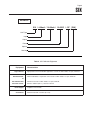
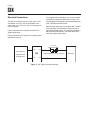
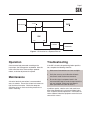
SIX
Signal Isolator/Converter
USER’S MANUAL
May 1991
© 1991 by Moore Industries-International, Inc.
No. 297-701-00 B
Table of Contents
Introduction
1
Description
1
Calibration
1
Installation
5
Operation
7
Maintenance
7
Troubleshooting
7
HR.
DELIVERY
8
4
United States/Canada
TOLL FREE
1-800-999-2900
United Kingdom
FREE PHONE
0800 525107
Australia
TOLL FREE
008 251928
Ask for the STAR Center
16650 Schoenborn Street
Sepulveda, California 91343, U.S.A.
Tel: (818) 894-7111 • Tlx: 65-1322
FAX: (818) 891-3297
CONNECT (MacNet): MIISEPULVEDA
1 Lloyds Court, Manor Royal, Crawley
W. Sussex RH10-2QU, United Kingdom
Tel: 0293 514488 • Tlx: 87667
FAX: 0293 536852
Moore Industries’ STAR* Center has a
wide variety of quality instrumentation
in stock and ready to ship.
• Signal Transmitters
• Temperature Transmitters
• P/I and I/P Converters
• Isolators and Converters
• Indicators and Displays
• Alarm Trips
• Integrators and Totalizers
• Power Transducers
• Instrument Power Supplies
• Racks, Rails and Enclosures
Most instruments can be customized
to meet your needs. Even then, you’ll
never have to wait more than a few days.
Moore Industries
3/18 Resolution Drive, Caringbah
New South Wales 2229, Australia
Tel: (02) 525-9177 • Tlx: 790-75914
FAX: (02) 525-7296
CENTER
* Support, Technical Assistance, and Repair (our Quick-Ship Facility)
SIX
Page 1
Introduction
Moore Industries’ Signal Isolator/Converter (SIX) is a
DIN-style, loop-powered device, used to provide
complete isolation of instrumentation input and
output. This helps eliminate faulty readings in
measurement and control equipment caused by
ground loops, electrical interference, or motor noise.
This manual provides a brief description of the SIX, a
list of performance and functional specifications, a
calibration procedure, operations notes, and troubleshooting information.
Notes and Cautions, where they appear in text or
illustrations, are provided to assist the user in
avoiding operational inconveniences (Notes), or
practices that otherwise might result in damage to
the unit (Cautions).
Description
The SIX is loop-powered. When connected in a 1242 Vdc loop, it converts a standard process current
or voltage signal to a proportional, isolated 4-20 or
10-50 mA output; breaking the galvanic path between a transmitted signal source and its receiving
device.
The unit is packaged in a compact, DIN-style housing that snaps easily on to G-rail mounting hardware
(DIN EN50035). This makes it ideal for use in high
density installations.
Table 1 consists of the SIX performance and functional specifications.
Options
Units may be ordered with RFI-filtered terminals and
case assembly (RF Option). RF-equipped units
provide RFI/EMI protection up to 50V/M - abc =
±0.1% F.S., as defined by SAMA standard 33.1.
Contact your Sales Representative or Moore Industries for more information on available SIX options
and compatible devices.
Serial Number. A complete history of every unit
sold and serviced by Moore Industries is kept at the
factory. This data is keyed to each unit’s serial
number. If service data is required on an SIX,
providing the factory with the unit serial number will
allow our highly skilled technicians to better assist
you.
The SIX serial number is located on a label affixed to
the side panel of the unit.
Model Number. Moore Industries' model numbers
identify the type of instrument, functional characteristics, operating parameters, any options ordered,
and housing type. If all accompanying documentation for a unit is missing, the model number may be
used to obtain technical information.
The model number for the SIX is located on the
same label as its serial number.
The example following Table 1 is provided to assist
in deciphering the fields of the SIX model number.
Controls
The SIX has Zero and Span potentiometers located
on the front panel of the unit. On older units these
were labeled:
for Zero, and
for Span.
On newer the words “ZERO” and “SPAN” may be
used to identify the potentiometers.
Calibration
Prior to unit shipment, each SIX is calibrated and
tested according to Moore Industries’ strict quality
control guidelines. It is recommended, however, that
a bench check of potentiometer settings and output
levels be performed before placing the SIX into
service.
SIX
Page 2
Table 1. SIX Specifications
Characteristics
Input
Specifications
Factory-set. Available ranges are:
0 to 20 mA
4 to 20 mA
–1 to +1 mA
0 to 10 V
1 to 5 V
0 to 1 V
Output
Factory-set. 4 to 20, or 10 to 50 mA.
Power
2-wire loop-power; 12 to 42 Vdc.
Performance
Isolation: Input and output are transformer-isolated with no galvanic path (dc connection)
up to 500 Vrms.
Frequency Response: 10 Hz at the 3 dB point.
Maximum Input Over-range: ±60 V
Input Impedance: 1.0 Mohm for voltage inputs; 50ohms for 4-20 mA input;
1 kohm for –1 to +1 mA input.
Load Capability: 4-20 mA into 1500ohms; limited to 50 mA, maximum.
Power Supply Effect: Less than 0.05% of span over the full power supply range.
Adjustability
Calibration Accuracy: ±0.1% of span.
Zero potentiometer adjusts unit zero to within ±5% of span.
Span potentiometer allows for 100% adjustment, ±10%, with full-scale input.
Environmental
Ratings
Weight
RFI/EMI Effect: Without RF Option, effect is negligible @ 25 V/m at typical communications frequencies. With RF, protection of 50 V/m-abc = ±0.1% F.S., as defined by SAMA
Standard 33.1.
Ambient Operating Temperature Range: –30 to +82 °C (–22 to +180 °F).
Temperature Change Effect on Unit Operation: 0.015% of span per °C change over a
0 to 70 °C range.
Approximately 215 grams (7.6 ounces).
NOTE: Refer to Installation Section of this manual for unit dimensions.
Calibration Equipment
Calibration Setup
Table 2 lists the calibration equipment required for this
bench check procedure. This equipment is not
supplied with the unit.
Figure 1 shows the calibration setup for the SIX. To
check or calibrate the SIX, connect the unit as shown
in the illustration, and apply the power according
specification (refer to the specifications table and the
model number of your unit).
SIX
Page 3
EXAMPLE
SIX / 4-20mA / 10-50mA / 12-42DC / -RF
[DIN]
Unit Type
Input
Output
Power
Options
Housing
Table 2. SIX Calibration Equipment
Equipment
Signal Source
DC milliammeter
Characteristics
Appropriate for the intended SIX application, accurate to within ±0.05% of span, minimum
Fluke model 8899, or equivalent unit accurate to within ±0.05% of span, minimum.
or
DC voltmeter with
Precision resistor
Power Supply
Screwdriver
Voltmeter accurate to within ±0.05% of span, minimum.
Resistor: 250ohm (±0.1%), rated for 4-20 mA.
Capable of 12 to 42 Vdc.
Slotted head, width 2.54 mm (0.1 inch).
SIX
Page 4
MILLIAMMETER
+
SIGNAL
SOURCE
– IN
+
+ PS
SIX
–
+
–
+ IN
12-42 Vdc
POWER
SOUCE
(SEE NOTE)
–
– PS
+
–
VOLTMETER
NOTE: Either milliammeter or voltmeter may be used for monitoring output.
Figure 1. SIX Calibration Setup
Note that there are no internal adjustments or settings
to effect on the SIX. Disassembly of any kind is not
recommended.
After applying power, allow approximately five minutes for stabilization/warm-up.
Calibration Procedures
There are two options for monitoring the output of the
SIX shown in the figures; either a dc milliammeter or
a dc voltmeter with load resistor may be used to
monitor and set output levels.
1. With the calibration setup complete, adjust both
potentiometers 15 turns counterclockwise, then
7.5 turns clockwise (mid-scale).
2. Simulate zero percent input.
3. Adjust zero potentiometer until milliammeter
reads 4 mA for 4-20 mA units, 10 mA for
10-50 mA units, or until voltmeter reads 1 volt.
CAUTION
To avoid damaging the housings, use a
screwdriver with a head not wider than
2.54 mm (0.1 inch) to adjust the zero and
span potentiometers.
4. Set input to 100 percent.
5. Adjust span potentiometer until milliammeter
reads 20 mA for 4-20 mA units, 50 mA for
10-50 mA units, or until voltmeter reads 5 volts.
6. Repeat steps 2 through 5 until zero and 100
percent readings are stable, ±0.1%.
SIX
Page 5
Installation
In this manual, the installation of the SIX is divided
into two phases: physically mounting the unit, and
making the electrical connections. It is recommended that the unit(s) be mounted before making
any connections.
Mounting
When mounting the SIX, make every effort to install it
in an area that is relatively free of dust, moisture, and
corrosive materials.
To mount the unit on a DIN-style G-rail, insert the
metal clip on the unit’s back panel under the top lip of
the rail. Pivoting on the clip, press down firmly until
the SIX snaps into place.
If it becomes necessary to remove the unit, grasp the
bottom of its front panel and lift upward.
NOTE
The SIX has no case ground connection.
If possible, avoid mounting the unit in any
electrical field. Secure the case to a
good conductor at zero potential.
Figure 2 shows the mounting dimensions for the SIX.
25.40 mm
(1.0 in)
119 mm
(4.67 in)
+IN -IN +PS -PS
80 mm
(3.15 in)
SIX
SIGNAL
ISOLATOR
SPAN
ZERO
Figure 2. SIX Outline Dimensions
SIX
Page 6
Electrical Connections
The SIX has four terminals on its front panel. They
are labeled “+IN” and “–IN” for connection of the
signal input, and “+PS” and “–PS” for connection of
the unit’s output.
Figure 3 illustrates the connection of the SIX in a
generic application.
To complete these connections, use a small, slotted
screwdriver to loosen the SIX terminal screws, and
slip the appropriate stripped wire end into the terminal
hole. Tighten the terminal screw.
Both the input and output may be grounded. The SIX
input and output are transformer-isolated with no dc
connection between them. This isolation provides 67
dB common mode rejection, and allows the input to
float with respect to the output.
Figure 4 shows the unit connected in another typical
operational scenario.
12-42 Vdc
POWER SOURCE
+ IN
+ PS
+
–
–
FIELD SERVICE
(NON-ISOLATED
TRANSMITTER)
(ISOLATED 4-20 or 10-50 mA SIGNAL)
SIX
– IN
– PS
Figure 3. SIX Typical Installation Hookup
RECEIVER
+
SIX
Page 7
+
TRANSMITTER
1-5 Vdc
DCS
–
–IN
+IN
SIX
–PS
+PS
+
POWER
–
–
RECORDER
+
Figure 4. SIX Installed as a Repeater/Diverter
Operation
Troubleshooting
Once mounted and connected according to the
instructions, the SIX operates unattended. After the
initial calibration of the Zero and Span potentiometers, no further adjustment is required.
If the SIX is found to be performing below specification, complete the following checklist:
Maintenance
A check of terminal connections is recommended
every six months. Ensure that all terminal screws are
tight and free of corrosion. Check that adequate
ventilation exists, or that heat sinking materials are
used in mounting.
1. Make sure all connections are clean and tight.
2. Verify the accuracy and calibration of bench
instruments used to take measurements.
3. Ensure that signal and power levels in the
instrumentation loop have not changed since the
unit was installed. Make sure that power is
within specified limits (refer to table 1).
If problems persist, note the serial and model numbers of the offending unit, and contact Moore Industries’ Customer Service Department. Instructions for
return of Moore Industries equipment are on the back
cover of this manual.
Declaration of Conformity
EMC Directive 89/336/EEC
Manufacturer’s Name:
Manufacturer’s Address:
Moore Industries-International, Inc.
16650 Schoenborn Street
North Hills, CA 91343-6196
USA
Declares that the product(s):
Product Name:
SIX
MODEL
Model Number(s):
SIX
/
INPUT
*
/
OUTPUT
/
*
POWER
12-42VDC
/
OPTIONS
*
/
HOUSING
*
*Indicates any input, output and housing as stated on the product data sheet.
Conforms to the following EMC specifications:
EN50081-2, 1993, Generic Emissions Standard, Industrial Environment.
EN50082-2, 1995, Generic Immunity Standard, Industrial Environment.
Supplemental Information:
None.
Janurary 22, 1999
Date
______________________________
Fred Adt
Quality Assurance Director
_____________________________________
Robert Stockham
Moore Industries-International, Inc.
European Contact: Your Local Moore Industries Sales and Service Office
RETURN PROCEDURES
To return equipment to Moore Industries for repair, follow these four steps:
1. Call Moore Industries and request a Returned Material Authorization (RMA) number.
Warranty Repair –
If you are unsure if your unit is still under warranty, we can use the unit’s serial number
to verify the warranty status for you over the phone. Be sure to include the RMA
number on all documentation.
Non-Warranty Repair –
If your unit is out of warranty, be prepared to give us a Purchase Order number when
you call. In most cases, we will be able to quote you the repair costs at that time.
The repair price you are quoted will be a “Not To Exceed” price, which means that the
actual repair costs may be less than the quote. Be sure to include the RMA number on
all documentation.
2. Provide us with the following documentation:
a) A note listing the symptoms that indicate the unit needs repair
b) Complete shipping information for return of the equipment after repair
c) The name and phone number of the person to contact if questions arise at the factory
3. Use sufficient packing material and carefully pack the equipment in a sturdy shipping
container.
4. Ship the equipment to the Moore Industries location nearest you.
The returned equipment will be inspected and tested at the factory. A Moore Industries
representative will contact the person designated on your documentation if more information is
needed. The repaired equipment, or its replacement, will be returned to you in accordance with
the shipping instructions furnished in your documentation.
WARRANTY DISCLAIMER
THE COMPANY MAKES NO EXPRESS, IMPLIED OR STATUTORY WARRANTIES (INCLUDING ANY WARRANTY OF MERCHANTABILITY OR OF FITNESS
FOR A PARTICULAR PURPOSE) WITH RESPECT TO ANY GOODS OR SERVICES SOLD BY THE COMPANY. THE COMPANY DISCLAIMS ALL WARRANTIES ARISING FROM ANY COURSE OF DEALING OR TRADE USAGE, AND
ANY BUYER OF GOODS OR SERVICES FROM THE COMPANY ACKNOWLEDGES THAT THERE ARE NO WARRANTIES IMPLIED BY CUSTOM OR
USAGE IN THE TRADE OF THE BUYER AND OF THE COMPANY, AND THAT
ANY PRIOR DEALINGS OF THE BUYER WITH THE COMPANY DO NOT IMPLY THAT THE COMPANY WARRANTS THE GOODS OR SERVICES IN ANY
WAY.
ANY BUYER OF GOODS OR SERVICES FROM THE COMPANY AGREES
WITH THE COMPANY THAT THE SOLE AND EXCLUSIVE REMEDIES FOR
BREACH OF ANY WARRANTY CONCERNING THE GOODS OR SERVICES
SHALL BE FOR THE COMPANY, AT ITS OPTION, TO REPAIR OR REPLACE
THE GOODS OR SERVICES OR REFUND THE PURCHASE PRICE. THE
COMPANY SHALL IN NO EVENT BE LIABLE FOR ANY CONSEQUENTIAL OR
INCIDENTAL DAMAGES EVEN IF THE COMPANY FAILS IN ANY ATTEMPT
TO REMEDY DEFECTS IN THE GOODS OR SERVICES , BUT IN SUCH CASE
THE BUYER SHALL BE ENTITLED TO NO MORE THAN A REFUND OF ALL
MONIES PAID TO THE COMPANY BY THE BUYER FOR PURCHASE OF THE
GOODS OR SERVICES.
United States • [email protected]
Tel: (818) 894-7111 • FAX: (818) 891-2816
Australia • [email protected]
Tel: (02) 8536-7200 • FAX: (02) 9525-7296
© 2007 Moore Industries-International, Inc.
ANY CAUSE OF ACTION FOR BREACH OF ANY WARRANTY BY THE
COMPANY SHALL BE BARRED UNLESS THE COMPANY RECEIVES
FROM THE BUYER A WRITTEN NOTICE OF THE ALLEGED DEFECT OR
BREACH WITHIN TEN DAYS FROM THE EARLIEST DATE ON WHICH THE
BUYER COULD REASONABLY HAVE DISCOVERED THE ALLEGED DEFECT OR BREACH, AND NO ACTION FOR THE BREACH OF ANY WARRANTY SHALL BE COMMENCED BY THE BUYER ANY LATER THAN
TWELVE MONTHS FROM THE EARLIEST DATE ON WHICH THE BUYER
COULD REASONABLY HAVE DISCOVERED THE ALLEGED DEFECT OR
BREACH.
RETURN POLICY
For a period of thirty-six (36) months from the date of shipment, and under
normal conditions of use and service, Moore Industries ("The Company") will
at its option replace, repair or refund the purchase price for any of its manufactured products found, upon return to the Company (transportation charges
prepaid and otherwise in accordance with the return procedures established
by The Company), to be defective in material or workmanship. This policy
extends to the original Buyer only and not to Buyer's customers or the users
of Buyer's products, unless Buyer is an engineering contractor in which case
the policy shall extend to Buyer's immediate customer only. This policy shall
not apply if the product has been subject to alteration, misuse, accident, neglect or improper application, installation, or operation. THE COMPANY
SHALL IN NO EVENT BE LIABLE FOR ANY INCIDENTAL OR CONSEQUENTIAL DAMAGES.
Belgium • [email protected]
Tel: 03/448.10.18 • FAX: 03/440.17.97
The Netherlands • [email protected]
Tel: (0)344-617971 • FAX: (0)344-615920
China • [email protected]
Tel: 86-21-62491499 • FAX: 86-21-62490635
United Kingdom • [email protected]
Tel: 01293 514488 • FAX: 01293 536852
Specifications and Information subject to change without notice.


![ECT[DIN] [DIN] - Moore Industries International](http://vs1.manualzilla.com/store/data/005778735_1-93255c4f7d497ff32afcfe496e72d982-150x150.png)