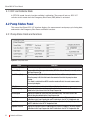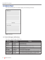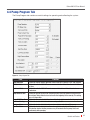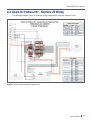
1
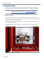
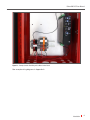
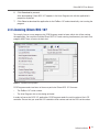
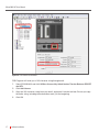
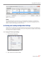
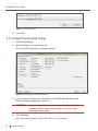
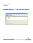
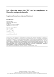
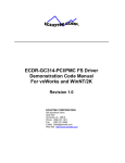
Automated Chemical Optimization
iCHEM™ ROC 107
USER MANUAL
INSTALLATION, SETUP, and OPERATION
FOR USE WITH THE FLOBOSS™ 107 AND ROCLINK™ 800
iChem ROC 107 User Manual
The iChem™ brand is trademarked by PCS Ferguson.
These documents and materials are copyrighted by PCS Ferguson.
© 2014 All rights reserved.
The FloBoss and ROCLINK are licensed Emerson products.
For information contact:
PCS Ferguson
3771 Eureka Way
Frederick, CO 80516
Phone: 720-407-3550
Fax: 720-407-3540
Email: [email protected]
Website: www.pcsferguson.com
1

iChem ROC 107 User Manual
Table of Contents
1 Introduction . . . . . . . . . . . . . . . . . . . . . . . . . . . . . . . . . . . . . . . . . . . . . . . . . . . . 5
1.1 Abbreviations and Acronyms. . . . . . . . . . . . . . . . . . . . . . . . . . . . . . . . . . . . . . . . . . . . . . 6
1.2 Safety Overview and Symbols . . . . . . . . . . . . . . . . . . . . . . . . . . . . . . . . . . . . . . . . . . . . . 6
1.3 System Overview. . . . . . . . . . . . . . . . . . . . . . . . . . . . . . . . . . . . . . . . . . . . . . . . . . . . . . . 7
1.3.1 FloBoss Hardware. . . . . . . . . . . . . . . . . . . . . . . . . . . . . . . . . . . . . . . . . . . . . . . . . . . . . . . . . . . . . 7
1.3.2 ROCLINK™ 800 User Interface. . . . . . . . . . . . . . . . . . . . . . . . . . . . . . . . . . . . . . . . . . . . . . . . . . . 9
1.3.3 iChem™ ROC 107 User Interface. . . . . . . . . . . . . . . . . . . . . . . . . . . . . . . . . . . . . . . . . . . . . . . . 11
2 Software Installation . . . . . . . . . . . . . . . . . . . . . . . . . . . . . . . . . . . . . . . . . . . . 12
2.1 Installing ROCLINK™ 800 . . . . . . . . . . . . . . . . . . . . . . . . . . . . . . . . . . . . . . . . . . . . . . . 12
2.1.1 Logging in the First Time. . . . . . . . . . . . . . . . . . . . . . . . . . . . . . . . . . . . . . . . . . . . . . . . . . . . . . . 12
2.2 Loading iChem ROC 107 . . . . . . . . . . . . . . . . . . . . . . . . . . . . . . . . . . . . . . . . . . . . . . . . 14
2.3 Licensing iChem ROC 107 . . . . . . . . . . . . . . . . . . . . . . . . . . . . . . . . . . . . . . . . . . . . . . . 16
2.4 Saving and Loading Configuration Settings. . . . . . . . . . . . . . . . . . . . . . . . . . . . . . . . . . . 18
2.4.1 Saving TLP Points and Settings. . . . . . . . . . . . . . . . . . . . . . . . . . . . . . . . . . . . . . . . . . . . . . . . . . 18
2.4.2 Loading Previously Saved Settings. . . . . . . . . . . . . . . . . . . . . . . . . . . . . . . . . . . . . . . . . . . . . . . 19
3 Setup and Calibration. . . . . . . . . . . . . . . . . . . . . . . . . . . . . . . . . . . . . . . . . . . . 20
3.1 Mapping I/O Points. . . . . . . . . . . . . . . . . . . . . . . . . . . . . . . . . . . . . . . . . . . . . . . . . . . . . 20
3.1.1 Tank Level TLP. . . . . . . . . . . . . . . . . . . . . . . . . . . . . . . . . . . . . . . . . . . . . . . . . . . . . . . . . . . . . . 21
3.1.2 PD Flow Meter TLP. . . . . . . . . . . . . . . . . . . . . . . . . . . . . . . . . . . . . . . . . . . . . . . . . . . . . . . . . . . 22
3.1.3 Injection Pressure TLP . . . . . . . . . . . . . . . . . . . . . . . . . . . . . . . . . . . . . . . . . . . . . . . . . . . . . . . . 23
3.1.4 Emergency Shutdown (ESD) DIN TLP . . . . . . . . . . . . . . . . . . . . . . . . . . . . . . . . . . . . . . . . . . . . . 24
3.1.5 Pump Control DOUT TLP. . . . . . . . . . . . . . . . . . . . . . . . . . . . . . . . . . . . . . . . . . . . . . . . . . . . . . . 25
3.1.6 Flow Switch TLP. . . . . . . . . . . . . . . . . . . . . . . . . . . . . . . . . . . . . . . . . . . . . . . . . . . . . . . . . . . . . 26
3.2 Calibrating the Flow Meter. . . . . . . . . . . . . . . . . . . . . . . . . . . . . . . . . . . . . . . . . . . . . . . 27
3.2.1 Calibrating the PD Meter. . . . . . . . . . . . . . . . . . . . . . . . . . . . . . . . . . . . . . . . . . . . . . . . . . . . . . . 27
3.2.2 Calibrating the Tank Level. . . . . . . . . . . . . . . . . . . . . . . . . . . . . . . . . . . . . . . . . . . . . . . . . . . . . . 27
3.2.3 Calibrating the Injection Pressure. . . . . . . . . . . . . . . . . . . . . . . . . . . . . . . . . . . . . . . . . . . . . . . . 28
3.3 Setting Up Cycles and Volume . . . . . . . . . . . . . . . . . . . . . . . . . . . . . . . . . . . . . . . . . . . . 28
3.3.1 Setting Daily Volume. . . . . . . . . . . . . . . . . . . . . . . . . . . . . . . . . . . . . . . . . . . . . . . . . . . . . . . . . . 29
3.3.2 Setting Contract Hour. . . . . . . . . . . . . . . . . . . . . . . . . . . . . . . . . . . . . . . . . . . . . . . . . . . . . . . . . 29
3.3.3 Setting Pump Cycle Interval . . . . . . . . . . . . . . . . . . . . . . . . . . . . . . . . . . . . . . . . . . . . . . . . . . . . 29
Table of Contents
2
iChem ROC 107 User Manual
4 Controls and Features . . . . . . . . . . . . . . . . . . . . . . . . . . . . . . . . . . . . . . . . . . . 30
4.1 Operation Modes. . . . . . . . . . . . . . . . . . . . . . . . . . . . . . . . . . . . . . . . . . . . . . . . . . . . . . 30
4.1.1 AUTO Mode. . . . . . . . . . . . . . . . . . . . . . . . . . . . . . . . . . . . . . . . . . . . . . . . . . . . . . . . . . . . . . . . . 30
4.1.2 Manual Mode. . . . . . . . . . . . . . . . . . . . . . . . . . . . . . . . . . . . . . . . . . . . . . . . . . . . . . . . . . . . . . . 30
4.1.3 OFF and Calibrate Mode. . . . . . . . . . . . . . . . . . . . . . . . . . . . . . . . . . . . . . . . . . . . . . . . . . . . . . . 31
4.2 Pump Status Panel. . . . . . . . . . . . . . . . . . . . . . . . . . . . . . . . . . . . . . . . . . . . . . . . . . . . . 31
4.2.1 Pump Status Fields and Functions . . . . . . . . . . . . . . . . . . . . . . . . . . . . . . . . . . . . . . . . . . . . . . . 31
4.2.2 Emergency Shut Down Button. . . . . . . . . . . . . . . . . . . . . . . . . . . . . . . . . . . . . . . . . . . . . . . . . . .32
4.2.3 ON/OFF Buttons . . . . . . . . . . . . . . . . . . . . . . . . . . . . . . . . . . . . . . . . . . . . . . . . . . . . . . . . . . . . . 32
4.2.4 Custom Batch Fields. . . . . . . . . . . . . . . . . . . . . . . . . . . . . . . . . . . . . . . . . . . . . . . . . . . . . . . . . . 32
4.3 Alarms Panel . . . . . . . . . . . . . . . . . . . . . . . . . . . . . . . . . . . . . . . . . . . . . . . . . . . . . . . . . 33
4.3.1 Alarm Messages and Meanings . . . . . . . . . . . . . . . . . . . . . . . . . . . . . . . . . . . . . . . . . . . . . . . . . 33
4.4 Pump Program Tab. . . . . . . . . . . . . . . . . . . . . . . . . . . . . . . . . . . . . . . . . . . . . . . . . . . . . 34
4.4.1 PD Meter Calibration. . . . . . . . . . . . . . . . . . . . . . . . . . . . . . . . . . . . . . . . . . . . . . . . . . . . . . . . . . 35
4.4.2 Tank Level Calibration. . . . . . . . . . . . . . . . . . . . . . . . . . . . . . . . . . . . . . . . . . . . . . . . . . . . . . . . . 36
4.4.3 INJ Pressure Calibration. . . . . . . . . . . . . . . . . . . . . . . . . . . . . . . . . . . . . . . . . . . . . . . . . . . . . . . 36
4.5 Pump Cycles Tab . . . . . . . . . . . . . . . . . . . . . . . . . . . . . . . . . . . . . . . . . . . . . . . . . . . . . . 37
4.6 Pump History Tab. . . . . . . . . . . . . . . . . . . . . . . . . . . . . . . . . . . . . . . . . . . . . . . . . . . . . . 38
4.7 I/O TLP Assignments Tab . . . . . . . . . . . . . . . . . . . . . . . . . . . . . . . . . . . . . . . . . . . . . . . . 39
5 Common Tasks. . . . . . . . . . . . . . . . . . . . . . . . . . . . . . . . . . . . . . . . . . . . . . . . . 40
5.1 Viewing History and Events. . . . . . . . . . . . . . . . . . . . . . . . . . . . . . . . . . . . . . . . . . . . . . . 40
5.2 Clearing Alarms. . . . . . . . . . . . . . . . . . . . . . . . . . . . . . . . . . . . . . . . . . . . . . . . . . . . . . . 41
5.3 Running Custom Batches. . . . . . . . . . . . . . . . . . . . . . . . . . . . . . . . . . . . . . . . . . . . . . . . 41
5.4 Creating a User-Defined TLP. . . . . . . . . . . . . . . . . . . . . . . . . . . . . . . . . . . . . . . . . . . . . . 42
Appendix A: Wiring Diagrams . . . . . . . . . . . . . . . . . . . . . . . . . . . . . . . . . . . . . . . 43
A.1 iChem for FloBoss107 - Standard JB Wiring. . . . . . . . . . . . . . . . . . . . . . . . . . . . . . . . . . 43
A.2 iChem for FloBoss107 - Neptune JB Wiring . . . . . . . . . . . . . . . . . . . . . . . . . . . . . . . . . . 44
Appendix B: Troubleshooting and Known Issues. . . . . . . . . . . . . . . . . . . . . . . . . 45
3

iChem ROC 107 User Manual
Revision History
Date
Description
Initial Release
Version
1.0

4
iChem ROC 107 User Manual
1 Introduction
Purpose
This manual guides the user in installation, setup, calibration, and operation of the iChem™ ROC
107 chemical well tending application.
Audience
The iChem ROC 107 User Manual is intended for knowledgeable professionals in the natural gas
well industry with flow management software experience.
Scope
Chapter 1 Introduction
Provides an overview of the system described in this manual.
Chapter 2 Software Installation
Provides step-by-step installation instructions for the ROCLINK 800 and iChem ROC 107 software.
Chapter 3 Setup and Calibration
Details the tasks required for customizing and testing your chemical injection system.
Chapter 4 Controls and Features
Lists and describes each input field and function in the iChem ROC 107 application.
Chapter 5 Common Tasks
Describes procedures for other useful options in the ROC 107 application.
Appendices
Contains additional wiring diagrams and troubleshooting information.
5
Introduction
iChem ROC 107 User Manual
1.1 Abbreviations and Acronyms
DIN: Digital Input
DOUT: Digital Output
DP: Differential Pressure
EFM: Electronic Flow Meter
FB107: FloBoss 107, electronic flow computer
iChem™: Intelligent Chemical Pump, referring to the PCS Ferguson chemical injection system
I/O: Input/Output
LOI: Local Operator Interface
PC: Personal Computer
PD: Positive Displacement
PID: Proportional-Integral-Derivative
PLC: Programmable Logic Controller
RTU: Real Time Unit
TLP: Point Type, Logical number, and Parameter
1.2 Safety Overview and Symbols
This product and other chemical injection systems and components should only be operated by
trained and experienced personnel. Accidents can result in damage to equipment, chemical spills,
loss of natural gas, or other unintended consequences.
This manual contains Caution and Warning-related text to alert the user to potential hazards:
CAUTION
A Caution box indicates a potential for damage to equipment, loss of
data, or interruption of essential processes.
WARNING
A Warning box indicates likely damage to equipment or loss.
Introduction
6
iChem ROC 107 User Manual
1.3 System Overview
The iChem ROC 107 application is designed to integrate with the Emerson™ ROCLINK™ 800
(ROCLINK) configuration software and the Emerson™ FloBoss™ 107 (FB107) flow manager.
NOTE
For more details regarding the FloBoss 107 or ROCLINK 800, refer to the
appropriate Emerson documentation at http://www2.emersonprocess.
com/en-US/brands/roc/software/roclink800/Pages/roclink800.aspx.
1.3.1 FloBoss Hardware
ROCLINK and iChem ROC 107 run with the FloBoss flow manager hardware. The FloBoss 107
attaches to the outside of the pump and manages the injection volume and timing of the well. The
box has an LCD screen for basic operations.
The junction box wiring configuration determines the parameters for later mapping of the TLP
points and other set up tasks.
The images shown in Figure 1.1 and Figure 1.2 are examples. Your hardware setup may look
different.
Figure 1.1 Example of Standard Junction Box Wiring
7
Introduction
iChem ROC 107 User Manual
Figure 1.2 Example Junction Box Wiring with a Motor Control Board
See example wiring diagrams in Appendix A.
Introduction
8
iChem ROC 107 User Manual
1.3.2 ROCLINK™ 800 User Interface
ROCLINK 800 configuration software allows a remote user to monitor, configure, and calibrate the
FB107. ROCLINK also enables off-line management of gas meters, I/O, and Proportional-IntegralDerivative Feedback Control Loops (PIDs).
The ROCLINK user interface displays the modules installed in the FB107 backplane.
Top Menu
Configuration
Tree Menu
Figure 1.3 ROCLINK 800 User Interface
Double-click I/O items or modules in the Configuration Tree Menu to manage I/O types.
Use the Top Menu to set up your ROCLINK software for your system.
9
Introduction
iChem ROC 107 User Manual
If necessary, you can adjust the display of TLP points from text to numerical in the ROCLINK menu.
1. In the Top Menu, click Tools > Options.
2. Under Display TLP, select As Number.
Figure 1.4 ROCLINK 800 Options Dialog Box
Introduction
10
iChem ROC 107 User Manual
1.3.3 iChem™ ROC 107 User Interface
The ROC 107 application lets the user set chemical injection timing and volume. Once in AUTO
mode, the application measures and monitors flow injection volumes and adjusts each cycle based
on previous measurements. iChem ROC 107 can be used with any pump. However, each ROC 107
version is custom-built for the system and module slot.
Pump Status Panel
Alarms Panel
Pump Program Tab
Figure 1.5 iChem ROC 107 User Interface
Click the Apply button to save your changes, and click Update to refresh the screen and meter
readings.
Clicking AutoScan updates all readings every second by default.
11
Introduction
iChem ROC 107 User Manual
2 Software Installation
The ROCLINK™ 800 software must be installed and connected to a communication device.
NOTE
Consult your FloBoss 107 and ROCLINK 800 user documentation for
additional information not included in this manual.
2.1 Installing ROCLINK™ 800
To install ROCLINK from a CD-ROM:
1. Insert the disk into your PC and follow in the installation wizard instructions.
2. If any “User Account Control” messages appear, click Yes to allow ROCLINK to install.
3. Restart your PC when prompted to complete the installation.
To install ROCLINK 800 from a .zip file:
1. Extract all files in the .zip folder, and save the ROC folder in an appropriate location on your
PC.
2. Open the ROC folder and ROCLINK sub-folder.
3. Locate and open the setup file.
4. Follow the instructions in the Installation Wizard.
5. If any “User Account Control” messages appear, click Yes to allow ROCLINK to install.
6. Restart your PC when prompted to complete the installation.
2.1.1 Logging in the First Time
ROCLINK automatically creates a shortcut on your desktop.
1. To start ROCLINK, double-click the shortcut or locate the program in your Start menu.
Figure 2.1 ROCLINK 800 Shortcut
For more information on the ROCLINK 800 application, visit the following link:
http://www2.emersonprocess.com/en-US/brands/roc/software/roclink800/Pages/roclink800.aspx
Software Installation
12
iChem ROC 107 User Manual
2. Open the ROCLINK application.
Figure 2.2 ROCLINK 800 Login Screen
3. When the login screen appears, type your User ID and Password, and then click OK.
If you do not have an individual user id and/or password, click the User ID: text to
automatically log in with the default credentials (ID: “LOI” and Password: “1000”).
4. Locate the correct communication device for your FloBoss 107 configuration in the ROCLINK
Device Directory.
5. Right-click on the device’s corresponding PC port, and click Properties.
Figure 2.3 ROCLINK 800 Device Directory
13
Software Installation
iChem ROC 107 User Manual
6. Define Communication Parameters as necessary for your system.
The green Online indicator will replace the red Offline field on the ROCLINK interface when you
are successfully connected.
2.2 Loading iChem ROC 107
The FloBoss 107 allows up to six (6) user program slots. Loading the iChem ROC 107 application
requires the .bin file.
To install iChem ROC 107:
1. If necessary, extract the .bin file and save it in an appropriate location on your PC.
2. Start ROCLINK800 and connect to the FloBoss 107.
3. In the configuration tree, expand User Program and click Administrator.
Figure 2.4 User Program Administrator Path
Software Installation
14
iChem ROC 107 User Manual
Figure 2.5 User Program Administrator Dialog Box
4. Click the Browse... button to locate and open the ROC 107 .bin file on your PC.
5. Ensure the Download User Program File path is correct, and then click Download & Start.
Figure 2.6 Download User Program File
15
Software Installation
iChem ROC 107 User Manual
6. Click Download to proceed.
After downloading, iChem ROC 107 appears in the User Program slot with the application’s
properties displayed.
7. Click Close to download the application to the FloBoss 107 and automatically start running the
program.
2.3 Licensing iChem ROC 107
To correctly license a user program slot, PCS Ferguson needs to know which slot will be running
the application. You can have multiple iChem ROC 107 loads running simultaneously, but each user
program MUST have a license for each slot.
Figure 2.7 Top Menu Licensing Options
PCS Ferguson needs two items to license a particular iChem ROC 107 firmware:
•
The FloBoss 107 serial number
•
The User Program slot or slots being activated
In order to license the ROC 107 application, PCS Ferguson needs the serial number of the LCD
controller. Ensure that you send the LCD controller serial number and not the CPU serial number.
Software Installation
16
iChem ROC 107 User Manual
Figure 2.8 LCD Controller Serial Number
PCS Ferguson will send you a 105-character string through email.
1. Open ROCLINK 800 and click Utilities>License Key Administrator>Transfer Between DEVICE
and KEY.
2. Click Add License.
3. Copy the 105-character string from your email, and paste it into the text box. Ensure you copy
the entire string, including the exclamation mark (!) at the beginning.
4. Click OK.
17
Software Installation
iChem ROC 107 User Manual
Figure 2.9 Licensing Screenshot
Display
The separate display file is not necessary to use the application. The display is compiled into a
single .bin file for iChem ROC 107 in the FloBoss 107 and is included with the program load. The
display is under the User Program section of the tree.
2.4 Saving and Loading Configuration Settings
iChem ROC 107’s settings are not saved automatically, and can be overwritten when updating your
software version. Follow these procedures to save your settings before you update, and then reload
the settings when the update is complete.
2.4.1 Saving TLP Points and Settings
1. Click File>Save Configuration.
Figure 2.10 Save Configuration Menu Path
2. Type a name for the file and click Save.
Software Installation
18
iChem ROC 107 User Manual
Figure 2.11 Save File Dialog Box
3. Click Close.
2.4.2 Loading Previously Saved Settings
1. Click File>Download.
2. Locate and Open your configuration file.
The “Download Configuration” dialog box appears.
Figure 2.12 iChem ROC 107 Download Configuration
3. In the “Download Configuration” dialog box, select PCS Ferg Pump Status and
PCS Ferg Pump Program. See Figure 2.12.
CAUTION
You can overwrite gas flow measurement settings by clicking the
wrong check boxes when loading settings. Use caution when
selecting the check boxes.
4. Click Download.
Your saved settings appear in your iChem ROC 107 user interface.
19
Software Installation
iChem ROC 107 User Manual
3 Setup and Calibration
This section details the process for mapping and calibrating inputs and outputs for your system.
NOTE
The same output slots can accommodate multiple output functions.
3.1 Mapping I/O Points
Before running your pump system with iChem ROC 107, you must properly map the TLP points
based on your system configuration. The user must define these TLP points.
For each TLP point:
1. Click the [...] button next to each TLP point to assign it to the corresponding slot based on your
FloBoss setup.
Figure 3.1 I/O TLP Assignments Tab
2. Select the correct I/O type in the Point Type scrolling list.
3. Select the corresponding Logical Number for the slot.
4. Select the correct Parameter.
Setup and Calibration
20
iChem ROC 107 User Manual
3.1.1 Tank Level TLP
The Tank Level point uses analog input.
1. Select Analog Inputs in the Point Type scrolling list.
2. Select the corresponding Logical Number for the slot.
3. Select the correct Parameter.
Figure 3.2 Tank Level TLP Settings
21
Setup and Calibration
iChem ROC 107 User Manual
3.1.2 PD Flow Meter TLP
The PCI Flow Rate is always a pulse input.
Select the correct Point Type, Logical Number, and Parameter for each point based on your system
configuration.
Figure 3.3 PD Meter TLP Settings
Setup and Calibration
22
iChem ROC 107 User Manual
3.1.3 Injection Pressure TLP
Injection Pressure is an analog input.
Figure 3.4 Inj Pressure TLP Settings
23
Setup and Calibration
iChem ROC 107 User Manual
3.1.4 Emergency Shutdown (ESD) DIN TLP
The ESD is a discrete input.
Figure 3.5 ESD DIN TLP Settings
Setup and Calibration
24
iChem ROC 107 User Manual
3.1.5 Pump Control DOUT TLP
The Pump Control point is a digital output.
Figure 3.6 Pump Control DOUT TLP Settings
25
Setup and Calibration
iChem ROC 107 User Manual
3.1.6 Flow Switch TLP
The Flow Switch point is a digital input.
Figure 3.7 Flow Switch TLP Settings
Setup and Calibration
26
iChem ROC 107 User Manual
3.2 Calibrating the Flow Meter
The calibration controls are located on the Pump Program tab on the main iChem ROC 107
interface. NOTE: Click Apply in ROCLINK 800 when any field is changed.
3.2.1 Calibrating the PD Meter
1. Isolate the pump tank from the sight glass.
2. Mark the top of the fluid point on your sight glass.
3. Click the Start Pump Test button to run the test.
4. Record the low point of the fluid after the test runs,
and determine the difference.
5. Fill in the Observed TickDrop with the
difference in fluid level before and after the test.
6. Click Apply.
7. Click the Calculate kfactor button.
Figure 3.8 PD Meter Calibration
8. Click Update.
3.2.2 Calibrating the Tank Level
1. Set the High and Low Voltage Points.
a. Isolate the tank.
b. Draw down the sight glass.
c. Enter the Low Level and click Set.
d. Establish a level to the sight glass.
e. Enter the High Level and click Set.
2. Click Update.
3. Calculate Scale and Offset.
4. Click Update.
The ROC 107 calculates the current Tank Level.
27
Setup and Calibration
Figure 3.9 Tank Level Calibration
iChem ROC 107 User Manual
3.2.3 Calibrating the Injection Pressure
1. Set the High and Low Voltage Points.
a. Isolate the transducer.
b. Bleed gas into the atmosphere.
c. Set the Low Level.
d. Apply well pressure.
e. Set the High Level.
Figure 3.10 Injection Pressure Calibration
2. Click Update.
3. Calculate Scale and Offset.
4. Click Update.
The ROC 107 calculates the current Injection Pressure.
3.3 Setting Up Cycles and Volume
Once all data points are mapped, the pump is ready for operation.
You can enter the necessary cycle and volume settings on the main ROC 107 screen, in the Pump
Status panel and Pump Program and Pump Cycles tabs. NOTE: Click Apply in ROCLINK 800
when any field is changed.
Figure 3.11 Pump Status Panel and Tabs on the ROC 107 Interface
Setup and Calibration
28
iChem ROC 107 User Manual
3.3.1 Setting Daily Volume
In the Pump Status panel, enter the required injection volume per day in the Daily Volume field.
3.3.2 Setting Contract Hour
The Pump Contract Hour determines the time of day that the pump cycle starts. The clock uses a
24-hour format, with a default value of 8:00.
To change the default contract hour, type a new value in the Pump Contract Hour field on the
Pump Program tab.
3.3.3 Setting Pump Cycle Interval
The Cycle Frequency field in the Pump Status panel automatically updates based on the selected
Cycle Interval set on the Pump Cycles tab.
Figure 3.12 Cycle Interval in the Pump Cycles Tab
On the Pump Cycles tab, select the desired time between each pump cycle in the Cycle Interval
drop-down list. Figure 3.12 shows a pump configured to run every two hours.
Set the cycle interval to Daily when you want the pump to run once at the Daily Trigger Time each
day.
See Chapter “4 Controls and Features” for descriptions of each data field.
29
Setup and Calibration
iChem ROC 107 User Manual
4 Controls and Features
This section details the functions of all data fields in the iChem ROC 107 interface.
4.1 Operation Modes
The iChem ROC 107 features three operation modes:
“AUTO,” “Manual,” and “OFF and Calibrate.”
The Operation Mode drop-down menu is located on the Pump Program tab.
NOTE: Click Apply in ROCLINK 800 when any field is changed.
Figure 4.1 Pump Operation Drop-down Menu
4.1.1 AUTO Mode
In Auto mode, the iChem ROC 107 manages the measured injection of well chemicals. The
electronic flow meter detects the amount of fluid (to seven digits of precision) that is pumped into
the well after each injection cycle. iChem ROC 107 then adjusts the next pump cycle amount to
account for inaccuracies over or under the set volume per cycle. The flow meter causes the pump
to skip cycles or simply revise the volume of the next cycle.
The PUMP ON and OFF buttons are not available in Auto mode. Any Alarms cause the pump to
shut off, and switch the application to OFF/Calibrate mode. Warnings appear in the Warning box,
but will disappear after an Update. The user can define the Warning and Alarm parameters in the
Pump Program tab. All Warnings and Alarms are recorded in the event and history logs.
Custom batch injections can run in either Auto or Manual modes.
NOTE
If a scheduled cycle occurs in manual mode or during a batch run, the
application skips that cycle.
4.1.2 Manual Mode
Manual mode allows the user to turn the pump ON or OFF and to run custom batches.
NOTE
In Manual mode, the tank level will not update until eight (8) seconds after
the pump stops.
Controls and Features
30
iChem ROC 107 User Manual
4.1.3 OFF and Calibrate Mode
In OFF/CAL mode, the only function available is calibration. The pump will not run. ROC 107
switches to this mode when the Emergency Shut Down (ESD) button is activated.
4.2 Pump Status Panel
This area of the iChem ROC 107 interface displays live measurements and pump cycle timing data,
and contains the Emergency Shut Down and Batch functions.
4.2.1 Pump Status Fields and Functions
Figure 4.2 Pump Status Panel
Field
Default Pump Name
Current Mode
Cycle Timer (Secs)
Function
Allows the user to type a name for the pump.
Shows which of the three operation modes (OFF/CAL, Auto, or Manual) is currently set on
the Pump Program Tab.
When the pump is OFF, this field counts down the time until the next cycle starts.
When the pump is ON, this field counts the amount of time that the pump has been
running.
Daily Volume
Cycle Frequency
Current Cycle
Tank Level
Flow Rate
Injection Pressure
31
Controls and Features
If the mode is switched from AUTO to another mode or Batch, the count resumes when
the next cycle begins.
Sets the total volume to be injected daily, and displays the volume.
Displays the total number of pump cycles set to run on the current day. This value is
based on the Cycle Interval set in the Pump Program tab.
Displays the number of cycles that have occurred that day. This count resets at the
Contract Hour time defined in the Pump Program tab.
Displays the Tank Level reading from the pressure transducer. This entry requires
calibration in the Pump Program tab and TLP definition in the I/O TLP Assignments tab.
Displays the PD Meter reading. This entry requires calibration in the Pump Program tab
and TLP definition in the I/O TLP Assignments tab.
Displays the Injection Pressure reading from the Pressure Transducer. This entry requires
calibration in the Pump Program tab and TLP definition in the I/O TLP Assignments tab.
iChem ROC 107 User Manual
Field
Function
Cycle Volume
Displays the volume to be injected in the next cycle.
In AUTO and Batch modes, this field counts down while pumping.
In Manual mode, it counts up while pumping.
Displays the volume as measured by the PD meter for the current day, starting at the
Contract Hour time defined in the Pump Program tab.
Todays Volume
4.2.2 Emergency Shut Down Button
Field
Function
Emergency Shut Down
Button
Turns off the pump and switches the application to the OFF/CAL operation mode.
4.2.3 ON/OFF Buttons
Field
Function
ON Button
Pump State
OFF Button
NOTE
Turns ON Pump in MANUAL mode. This button is disabled in other modes.
PUMPON or PUMPOFF shows the current state of the pump.
Turns off pump in MANUAL or BATCH mode. Disabled in other modes.
To turn off the pump in AUTO mode, you must switch to MANUAL or
OFF/CAL.
4.2.4 Custom Batch Fields
Field
Function
Custom Batch Start
Batch Vol.
NOTE
Starts a custom Batch in AUTO or MANUAL mode.
Sets the volume for an instantaneous batch injection.
If a scheduled cycle occurs during batch mode, the cycle is skipped.
Controls and Features
32
iChem ROC 107 User Manual
4.3 Alarms Panel
This area of the iChem ROC 107 interface displays active Warnings and Alarms.
Figure 4.3 Alarms Panel
4.3.1 Alarm Messages and Meanings
These alarms trigger Emergency Shut Down.
Message
Low Tank
Low Flow
High Flow
Low Press
High Press
No Flow
Flow Switch
User Defined Low
User Defined High
Manual ESD
33
Controls and Features
Abbreviation
LO TNK ESD
LO FLO ESD
HI FLO ESD
LO PRES ESD
HI PRES ESD
NO FLO ESD
FLO SWEC ESD
USER LO ESD
USER HI ESD
MANUAL ESD
Meaning
The fluid level in the tank is low.
The flow volume is low.
The flow volume is high.
The flow pressure through the transducer is low.
The flow pressure through the transducer is high.
There is no fluid flow.
The flow switch has been triggered.
The associated user defined measurement is at the low threshold.
The associated user defined measurement is at the high threshold.
The user has clicked the Emergency Shut Down button.
iChem ROC 107 User Manual
4.4 Pump Program Tab
The Pump Program tab contains essential settings for operating and calibrating the system.
Figure 4.4 Pump Program Tab
Field
Function
Pump Operation
PD Meter Units
Defines the current mode of operation. Select from AUTO, Manual, or OFF and Calibrate.
Defines the units the ROC 107 uses to measure the flow. Select from Quarts, US Gallons,
or Liters.
Tank Level Units
Defines the units the ROC 107 uses to measure the tank level. Select from Inches or
Centimeters.
Pump Contract Hour
Defines the hour of the day when the pump restarts the Daily Volume measurement. At
the set hour, Todays Volume clears to zero for the beginning of the new day. This setting
uses a 24-hour clock.
Pump Off W Flow Alarm Defines the flow rate af which the alarm will activate eight seconds after the pump is off.
Tank Low Warning
Defines the level at which the tank low warning activates.
Tank Low Alarm
Defines the level at which the tank low alarm activates and shuts off the pump.
Low Flow Alarm
Defines the level at which the low flow alarm activates and shuts off the pump.
This function checks the flow pressure every 20 seconds after the pump starts and
continuously while pumping.
Controls and Features
34
iChem ROC 107 User Manual
Field
Function
High Flow Alarm
Low Pressure Alarm
High Pressure Alarm
Flow Switch
User Defined 1
Defines the level at which the high low alarm activates and shuts off the pump.
Defines the level at which the low pressure alarm activates and shuts off the pump.
Defines the level at which the high pressure alarm activates and shuts off the pump.
Optional flow switch that confirms flow. The switch uses digital input for ON or OFF.
Defines a data point, based on the User Defined TLP setup. The user can enable the point
for an Alarm or Warning flag.
User Defined 2
Defines a data point, based on the User Defined TLP setup. The user can enable the point
for an Alarm or Warning flag.
User Defined TLP
Defines a TLP for dynamic definitions of alarms or warnings.
Enable/Disable Buttons Allows the user to enable or disable any alarm or warning.
E=enabled, D=Disabled
Alarm/Warning Buttons Lets the user set the Flow Switch and User Defined points as Alarms or Warnings.
4.4.1 PD Meter Calibration
Field
Function
Test Time in Secs
Defines the amount of time the pump
runs during a positive displacement (PD)
meter calibration test.
Volume per Tick
Lets the user set the volume per tick
used in pump calibration.
Observed Tick Drop
During pump calibration, the user enters
how many ticks the fluid dropped in this
field.
kFactor
Displays the computed kFactor after
Calculate kFactor is clicked.
Computed Tick Drop
Displays the computed fluid drop, which
should match the Observed Tick Drop.
This measurement is based off Test
Time, Volume per Tick and the kFactor.
Changing the Test Time in Secs and
starting a pump test will compute a tick
drop based on the calibrated factor.
Start Pump Test Button Starts the pump test. Test Time and
Volume per Tick must be entered before
pressing this button. The pump runs for
time defined by the Test Time field.
Calculate kFactor
Measures PD meter pulses during the
Button
pump test and calculates the kFactor
for the injection system. You must run
the pump test before clicking this button
to calculate. When clicked, this button
computes the slope and offset of the
calibration.
35
Controls and Features
Figure 4.5 PD Meter Calibration Panel
iChem ROC 107 User Manual
4.4.2 Tank Level Calibration
Field
Low Level
High Level
Current Level
Calculate Scale and
Offset Button
Function
Enables the user to set the low level
entry for tank calibration. Click the Set
button when the fluid is at the low level
in tank.
Enables the user to set the high level
entry for tank calibration. Click the Set
button when the fluid is at the high level
in tank.
Displays the current fluide level in the
tank as measured eight (8) seconds
after the pump stops.
Calculates the linear curve the
transducer will follow for a specific
voltage based on the high and low
levels.
Figure 4.6 Tank Level Calibration
4.4.3 INJ Pressure Calibration
Field
Low Level
High Level
Current Press
Calculate Scale and
Offset Button
Function
Enables the user to set the low level
entry during pressure transducer
calibration for injection pressure.
Enables the user to set the high level
entry during pressure transducer
calibration for injection pressure.
Displays the current injection pressure.
Calculates the linear curve the
transducer will follow for a specific
voltage based on the high and low
levels.
Figure 4.7 Injection Pressure Calibration
Controls and Features
36
iChem ROC 107 User Manual
4.5 Pump Cycles Tab
This tab enables the user to set the timing for pump cycles at a weekly, monthly, and daily level.
Figure 4.8 Pump Cycles Tab
Field
Cycle Interval
Daily Trigger Time
Weekly
Monthly
D
E
37
Controls and Features
Function
Defines the amount of time between the start of pump cycles, in minutes, hours, or daily.
Defines the time the pump starts if the Cycle Interval is once Daily.
Alows the user to select specific days of week to pump. For every day, click Check All.
Allows the user to select specific days of the month to pump. During months shorther
than 31 days, the application skips the extra days. For every day, click Check All.
Indicates Disabled.
Indicates Enabled.
iChem ROC 107 User Manual
4.6 Pump History Tab
This tab displays statistics for chemical injection over time.
Figure 4.9 Pump History Tab
Field
Today Vol Since Start
Yesterdays Volume
Week Volume
Month Volume
Year Volume
Forever Volume
Batch Volume Today
Batch Volume Y’Day
Manual Volume Today
Manual Volume Y’Day
30 Day Volume
30 Day Target Vol
30 Day Err Volume
30 Day Batch Vol
30 Day Manual Vol
30 Day Ttl Cycles
30 Day Skip Cycles
Function
Volume injected since the contract hour.
Volume recorded in the previous 24-hours, from contract hour to contract hour.
Volume injected in a week period. This field resets on Sunday.
Volume injected in a month. This field resets on the 1st of each month.
Volume injected in a Year. This field resets on January 1st.
Volume injected since the application began tracking pump allocation.
Additional volume injected using custom batches.
Volume of custom batches added in the previous 24 hours, contract hour to contract hour.
Additional volume added manually.
Manual volume added in the previous 24 hours, contract hour to contract hour.
Volume injected in the previous 30 days.
Target volume for previous 30 days.
Difference between the 30 Day Target Vol and 30 Day Volume.
Volume injected as a custom batch in the last 30 days.
Volume manually added in the last 30 days.
Number of pump cycles that have occurred in the last 30 days.
Number of pump cycles skipped in the last 30 days.
Controls and Features
38
iChem ROC 107 User Manual
4.7 I/O TLP Assignments Tab
The user must map the TLP points on this tab prior to operation. See “3.1 Mapping I/O Points”
Figure 4.10 I/O TLP Assignments Tab
Field
Tank Lvl RawAD
Injection Pressure TLP
Pump Control DOUT
TLP
PD Flow Meter TLP
ESD DIN TLP
Flow Switch TLP
39
Controls and Features
Function
TLP point selected for the Tank Level transducer
TLP point selected for the Injection Pressure transducer.
TLP point for Digital Output control of the pump.
TLP point for Pulse Input for the positive displacement pump.
TLP point for Digital Input for Emergency Shut Down.
TLP point for Digital Input of Flow Switch.
iChem ROC 107 User Manual
5 Common Tasks
The following activities facilitate operation and maintenance of the EFM through iChem ROC 107.
5.1 Viewing History and Events
To view the Event Log:
1. Click View>Alarms.
2. Select From Device or From File to view the History, Alarms, or Events log.
Figure 5.1 View Alarms Menu Path
Figure 5.2 Sample Alarms Log
Common Tasks
40
iChem ROC 107 User Manual
5.2 Clearing Alarms
To clear alarms and restart the pump:
1. Click the Clear Alarms button in the Current Alarms panel.
Figure 5.3 Alarms Panel
2. Then, click Update.
NOTE
Alarms can also clear automatically. For example, the alarm will trigger
if the injection pressure dips below the low alarm level. If the injection
pressure then rises above the low alarm level, the alarm will automatically
clear.
5.3 Running Custom Batches
1. In AUTO or Manual mode, enter the volume to be injected
immediately in the Batch Vol. field.
2. Click the Custom Batch Start button to begin the batch injection.
The Pump Status panel updates as the batch runs.
Figure 5.4 Custom Batch
Functions
41
Common Tasks
iChem ROC 107 User Manual
5.4 Creating a User-Defined TLP
Extended soft points allow users to define data types.
Figure 5.5 User Defined TLP Functions
Users can set alarms and shut down the pump using any TLP point defined in the FloBoss 107.
1. Select and map the User Defined TLP point.
2. Match the TLP point to its data type.
3. Set up the warning or alarm levels as required.
Common Tasks
42
iChem ROC 107 User Manual
Appendix A: Wiring Diagrams
A.1 iChem for FloBoss107 - Standard JB Wiring
The following diagram shows an example wiring configuration.
Figure A.1 Standard Junction Box Wiring Example
43
Wiring Diagrams
iChem ROC 107 User Manual
A.2 iChem for FloBoss107 - Neptune JB Wiring
The following diagram shows an example wiring configuration using the Neptune Pump.
Figure A.2 Example Junction Box Wiring for Neptune Pump
Wiring Diagrams
44
iChem ROC 107 User Manual
Appendix B: Troubleshooting and
Known Issues
Problem: iChem will not license
Solution: Refer to Section 2.3
Problem: Pump will not start
Solution: Check wiring and refer to Section 3.1
Solution: Check operation and refer to Section 4.1
Problem: Pump starts, but no or Low Flow Detected
Solution: Check wiring and refer to Section 3.1
Solution: Check PD meter sensor is installed correctly
Solution: Isolate the PD meter and examine inside the PD meter gears for blockage or flaws
45
Troubleshooting and Known Issues
iChem ROC 107 User Manual
INTENTIONALLY
BLANK

46