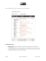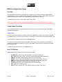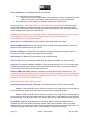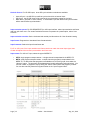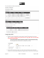
1
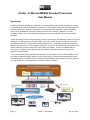
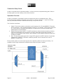
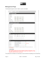
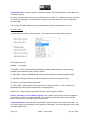
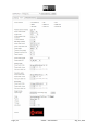
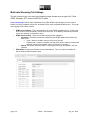
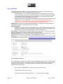
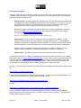
!
CSI!Digital!xCoder!User!
Manual!
!
!
!
March!12,!2015!
!
!
!
!
!
!!
xCoder - H.264 and MPEG2 Encoder/Transcoder
User Manual
Introduction
xCoder is a real time multi-function audio/video processing platform with a wealth of application capabiliy.
The flexible nature of the xCoder platform provides for a customizable solution that can integrate into any
workflow environment. Real time, file based, or mixed workflows are supported. xCoder is a platform,
which can be instatiated as common functions such as encoder, decoder, transcoder, or format
conversion. Best of all, it can combine these elements into a unique solution that can solve workflow
problems.
xCoder processing functions include decoding, encoding, transcoding, and streaming solution for HD and
SD signals. xCoder supports a very wide variety of input and output formats. xCoder can encode from
uncompressed sources, or transcode from compressed sources. The delivery format can be traditional
MPEG2-TS streams via IP or ASI interfaces, native RTP, or up to 16 multi-rate streams compliant with the
internet streaming formats of Apple HLS, Flash RTMP, or Silverlight. xCoder is compatible with any
media servier, including Wowza, Microsoft IIS, and Adobe Flash Media Server and includes CDN
integration support as well.
The xCoder processing engine includes CSI Digital’s very high quality, 2-pass, H.264 and MPEG2 multicore video encoding technology. With this core encoding engine, xCoder provides leading video quality
and bitrate savings. In addition, motion compensated based filtering and frame rate conversion provides
very high quality HD to SD downscaling and 50HZ to 60HZ conversions.
Page!|!1!
xCoder!–!User!Manual! !!!!!!!!!!!!!!!!!!!!!!!!!!!!!!!!!!!!!!!!!!!Aug!!18!,!2014!
!
!!
Connection Setup Guide
xCoder is controlled from a web based interface. xCoder comes with a separate setup guide. Refer to
the setup guide if you are installing a new xCoder machine.
Operation Overview
xCoder is composed of 3 separate functional components as shown in the diagram below. Each
functional block has separate configuration and control for maximum flexibility. In a given processing
flow, any combination of these 3 functional blocks may or may not be in use.
The 3 blocks are as follows
1. Splitter: This block provides a mechanism to split incoming ASI or IP based MPEG2-TS streams
and re-route them, or the individual programs in a MPTS. For example, a MPTS with 4 programs
in it, can be split into 4 separate SPTS MPEG2-TS steams which can be processed and/or
passthrough the xCoder platform.
2. Media Processing Engine (MPE): The MPE provides the video and audio processing functions
required for applications such as decoding, encoding, transcoding and format conversion. In
addition, AES scrambling, logo insertion, and a plethora of other media processing functions are
available in the MPE.
3. Mux: The Mux can passthrough and/or merge SPTS streams into MPTS streams. For example,
4 different SPTS MPEG2-TS streams created by the MPE can be combined into 1 MPTS
MPEG2-TS stream here.
Each processing block can route output signals to the neighboring blocks for further processing. It is
possible to loop a single media stream multiple times through the system if needed.
Page!|!2!
xCoder!–!User!Manual! !!!!!!!!!!!!!!!!!!!!!!!!!!!!!!!!!!!!!!!!!!!Aug!!18!,!2014!
!
!!
The 3 main steps to running xCoder are shown in the diagram below. The Splitter, MPE, and Mux each
have multiple channels of media processing within each function. Depending on the product model you
have.
STEP!1!
STEP!2!
STEP!3!
Configure!the!3!
functional!blocks!
and!save!the!
configuration!
Start!any!of!the!3!
functional!blocks.!!
Select!a!Configuration!
for!each!!
Start/Stop!each!channel!
within!each!functional!
block.!!Monitor!status.!
The xCoder user interface is accessed via any HTTP web browser. Along the top of the xCoder web
interface are the major user pages for xCoder: Splitter, MPE (Configuration, Control, Monitor, Log), Mux,
and Management
The Splitter page is used to configure and control the Splitter de-multiplexing functions.
The MPE Configuration page is used in Step 1 to define audio, video and network settings for
processing of audio/video channels . Parameters and settings are grouped together in user named
configuration profiles. You can create as many configuration profiles as you wish in the "Configuration"
page. These profiles can then be assigned to individual channels on the MPE Control page.
The MPE Control Page is used to start/stop a channel based on MPE configuration profiles.
The MPE Monitor Page is used to view characteristics of the real time audio/video signal being
processed on each channel.
The MPE Log page shows real time log information on channels running.
The Management page is used for network configuration (IP, NTP, and DNS configuration) of xCoder,
system restart controls, and software update.
Page!|!3!
xCoder!–!User!Manual! !!!!!!!!!!!!!!!!!!!!!!!!!!!!!!!!!!!!!!!!!!!Aug!!18!,!2014!
!
!!
Management Page
The Management page has 3 tabs: Network , System, and Update.
The System tab in this release is a re-boot switch for user convenience if operating from a remote facility.
Page!|!4!
xCoder!–!User!Manual! !!!!!!!!!!!!!!!!!!!!!!!!!!!!!!!!!!!!!!!!!!!Aug!!18!,!2014!
!
!!
The Network tab allows control of the network configuration of xCoder system. xCoder uses eth0 for
Data, and eth0 and/or eth1 for data output, and eth1 for Management. You can choose DHCP or static
settings for each interface. DNS and NTP settings are also available.
Indicators are shown that check the DNS and NTP addresses to see if they are reachable on the network.
Green indicator “ok” means the address is valid and the target is returning a ping. Failed means the IP
can not be reached (or pinged). This could be due to the target IP not returning ping which may be
normal for some systems.
NTP external reference is recommended for most installations. This can be an internet available NTP
reference server provided by a variety of organizations worldwide, or a private NTP reference on your
LAN. NTP provides a mechanism to lock the clock reference used for video/audio time stamps and
system reference times to an external source.
IMPORTANT NOTES :
When any network settings are changed including Ethernet, DNS, or NTP, then the settings will not take
effect until you select “Apply Changes”.
When Apply Changes is selected, data traffic on any running xCoder channels will be interrupted causing
interruption of video/audio signals.
Update Tab. This feature allows the user to poll for a software update available for xCoder. This feature
is disabled in evaluation versions of xCoder.
Page!|!5!
xCoder!–!User!Manual! !!!!!!!!!!!!!!!!!!!!!!!!!!!!!!!!!!!!!!!!!!!Aug!!18!,!2014!
!
!!
Splitter Configuration Guide
Description
The Splitter is an MPTS Program De-multiplexer, and ASI/IP to IP router.
The Splitter can take IP MPTS MPEG2-TS streams from the external Ethernet input, or ASI input, VSB
Tuner, or from the output of the internal Mux. The Splitter then de-multiplexes programs in a MPTS to
individual SPTS MPEG2-TS streams. These SPTS streams can be configured to be used as inputs for
the MPE(for transcoding), or routed to the MUX, or be sent to the external IP Ethernet output of the
chassis without further processing.
The splitter can be configured with a chassis that supports up to 4 ASI inputs, and up to 4 ethernet inputs.
The splitter also features a discover mode to identify what programs exist in an incoming stream and
provide information on the stream construction and codecs.
The splitter has 8 channels in its normal configuration. Higher number of channels are available in certain
product models.
Operation
The Splitter can be accessed from HTTP user interface by selecting the “Input Splitter” name on the top
of the user interface.
The!Splitter!has!the!following!main!controls!
Start!:!to!turn!on!the!Splitter!Function
Stop!:!to!stop!the!Splitter!Function
Restart!:!to!restart!a!Splitter!channel!
Status!:!to!open!detail!real!time!stream!information!on!running!splitter!channels
Save!Configuration!:!save!the!configuration!of!the!Splitter!settings.!!This!is!best!done!when!the!
splitter!is!not!running.!!If!you!change!configuration!of!the!Splitter!while!running,!a!dialog!box!will!
appear!asking!if!you!want!to!save!these!new!settings.!If!yes,!the!splitter!channels!which!have!
had!configurations!changed!will!be!stopped!and!restarted!at!that!time.
! Defaults:!If!selected,!the!user!will!be!prompted!to!set!all!channels!to!default!settings,!then!these!
can!be!saved.!!Default!settings!set!all!output!IP/ports!to!loopback!and!incremented!nonS
conflicting!ports.
! For!each!Channel,!there!are!these!parameters!to!configure
o Input!Interface!:!ASI!or!IP!or!Tuner.!
!
!
!
!
!
For IP input, multicast, unicast, and loopback address supported. Set IP to
0.0.0.0 for generic unicast input, and 127.0.0.1 for loopback input.
" 0.0.0.0 will catch all unicast inputs with a matching port.
Discover!=>!once!an!input!port!is!defined,!you!can!select!the!Discover!button. After a
few seconds, a Table will appear in the “Output” section that lists all the incoming
programs on the input port. For each program, PIDs, stream type, and codec is
displayed.
Output Format:
"
o
o
Page!|!6!
xCoder!–!User!Manual! !!!!!!!!!!!!!!!!!!!!!!!!!!!!!!!!!!!!!!!!!!!Aug!!18!,!2014!
!
!!
"
"
"
"
UDP or RTP. Both use MPEG2-TS , but RTP includes the addition of RTP
headers in the stream.
NIC: for systems with multiple Ethernet NIC interfaces, you can select any NIC
for each SPTS output. You can also select “lo” for loopback output.
• Setting a specific NIC with 127.0.0.1 also will result in loopback
IP/port setting. Each program will be output to a different IP/port as a SPTS.
multicast, unicast, and loopback address supported)
PMT Passthrough or Rewrite:
• Passthrough mode simply keeps the PAT/PMT structure of the incoming
stream and the outgoing SPTS has just 1 element in the PMT
• Rewrite: creates a new PAT/PMT for the stream with new PIDS.
The user interface of the Splitter is shown below with a step by step example.
Step 1: Configure input interface on channel 0 (or other channels) In this example we configure it for
unicast input 0.0.0.0 and port 5566.
Step 2: Select Discover Button, and if an MPTS is found the stream information is shown as below.
Step 3: Define output settings for each SPTS. Then select “Save Configuration”
!
Page!|!7!
xCoder!–!User!Manual! !!!!!!!!!!!!!!!!!!!!!!!!!!!!!!!!!!!!!!!!!!!Aug!!18!,!2014!
!
!!
!
Step 4: Start Channel 0 (or other channels) and monitor real time status.
!
Configuration Notes
! The Splitter MPTS places each program in the order of the Input Streams incoming MPTS
PAT/PMT table.
! To send the output SPTS to an internal component such as the MPE or Mux, use the loop back
“lo” output with address 127.0.0.1 with a unique port. Then configure the MPE or Mux receiving
configuration with the input 127.0.0.1 and port number.
Page!|!8!
xCoder!–!User!Manual! !!!!!!!!!!!!!!!!!!!!!!!!!!!!!!!!!!!!!!!!!!!Aug!!18!,!2014!
!
!!
MPE Configuration Page
Overview
The Application Configuration page allows you to define audio and video processing parameters and
network settings. You can create as many configuration profiles as you wish. These profiles can then be
assigned to individual channels in the corresponding "Control" section of the GUI.
To start/stop a channel you must navigate to the Control page.
NOTE: Any changes to the channel configuration settings or profiles will not take effect on an actively
running channel. For configuration changes to take effect, you must stop the active channel and restart it.
Configuration File Setting
The Configuration page is composed of several sub-tabs in the user interface for setting input, output,
and other signal settings.
CONFIG FILE:
You can create new configuration profiles by clicking the “Save As...” button. When clicked, you will be
prompted to enter a name for your new profile in the dialog box. These files are saved with extension .cfg
To clear settings to default values, select the “Defaults” button.
You can also choose previously saved configuration files from the pull down selector. Whenever you
change any configuration parameters, you must hit the "Save" button to store the changes and update
the configuration file.
To Delete a configuration file select the “Delete” button.
Input Tab Settings
Input interface: The following input interfaces are supported:
•
•
•
•
•
•
•
•
•
IP (MPEG2TS): IP/UDP input with RTP/MPEG-TS packets or MPEG-TS
RTP : Native RTP over IP/UDP. A SDP file is required(see below SDP file selector)
DVB-ASI: ASI input interface (requires optional ASI interface card)
HD-SDI: HD or SD uncompressed digital input (requires optional SDI input card)
HDMI: HD or SD uncompressed digital input (requires optional HDMI input card)
Analog: Composite SD (requires optional composite input card)
TS File: MPEG2 TS file on local hard disk drive or mounted drive.
HLS: Apple HTTP Streaming input.
ATSC: Digital Terrestrial VSB Tuner Interface (requires optional Tuner Card)
Page!|!9!
xCoder!–!User!Manual! !!!!!!!!!!!!!!!!!!!!!!!!!!!!!!!!!!!!!!!!!!!Aug!!18!,!2014!
!
Page!|!10!
!!
xCoder!–!User!Manual! !!!!!!!!!!!!!!!!!!!!!!!!!!!!!!!!!!!!!!!!!!!Aug!!18!,!2014!
!
!!
Source IP Address: For IP/UDP(MPEG2TS) input interface:
•
•
For unicast input there are two options
o Without the raw socket mode enabled : set IP address to 0.0.0.0 or to the input IP of eth0
o With the raw socket mode enabled : set IP address to the IP of the encoder (eth0)
For multicast input, set IP address to multicast IP address of the source to join
Raw Socket mode : Raw socket mode is not recommended for most applications. Without the Raw
Socket Mode enabled, the hardware NIC filters for the appropriate packets which is the most efficient
method. Raw socket mode sends all network traffic into the application level, and then packet filtering is
done at the application level which is less efficient.
WARNING: Raw Socket Mode can negatively impact the Ethernet bandwidth and is not recommended for
most installations. Please contact your CSI Digital support contact for further details and
recommendations for you particular installation.
Source port: For IP/UDP(MPEG2TS) input interface. Set to input stream port number.
Multicast IGMPv3 Source IP: For networks that require v3 IGMP multicast request/setup, enter the IP
address of the multicast source for your network.
SDP Server Address: For Native RTP input interface, a session description protocol file is required.
Enter the server URL and directory where the SDP file is located.
SDP Filename: For Native RTP input interface, enter the SDP filename.
RTCP For Native RTP input interface, enable RTCP time stamps if available from the source RTP
Audio Only This mode is available for MPEG2-TS input and output(via ASI or IP) If the incoming signal
has audio and video elements, then the video is removed and the output will only have audio element.
For an input with audio only, then the output is audio only.
HD-SDI or HDMI input mode: Select input resolution and frame rate from the pull down menu. If the
resolution/frame rate parameters are not set to match the incoming input signal resolution and frame rate
then xCoder will auto-detect the proper input resolution and frame rate. This will result in slower channel
start times since xCoder has to detect the input.
HDMI input does not support HDCP encryption
Repeat Last Frame when signal is missing: For HD-SDI mode only, this option can be enabled.
Disabled: when the HD-SDI input is removed or missing on a running channel, then the output of
the channel will stop. When the HD-SDI input is returned then the channel starts again.
Enabled : When the HD-SDI input is removed or missing on a running channel, then the output of
the channel will continue with the last good HD-SDI input video frame. It will appear as a frozen frame on
the output stream. This will remain frozen for a duration defined by the Frame Repeat Timeout parameter
Frame Repeat Timeout: When Repeat Last Frame when signal is missing is enabled, then this
parameter will control the duration that the last HD-SDI video frame is repeated. Set to 0 for infinite
repeat last frame, or a number other than 0 which will repeat the last frame for the value frame times. For
30 frame per second content, then value 30 would repeat for 1 second as an example.
Page!|!11!
xCoder!–!User!Manual! !!!!!!!!!!!!!!!!!!!!!!!!!!!!!!!!!!!!!!!!!!!Aug!!18!,!2014!
!
!!
Genlock Source: For HD-SDI inputs, three SDI synchronization methods are available
•
•
•
Internal Synch: the HD-SDI input will be synchronized with an internal clock
SDI Synch: the HD-SDI input will be used as the synchronization master for the input.
Black Burst: (optional on some chassis). A second BNC input with black burst synchronization
will be used to define synchronization.
Input resolution preset: For IP/UDP(MPEG2TS) or ASI input interface, select input resolution and frame
rate from pull down menu. For custom resolutions that are not present as a preset option, select “User
Override.
Input resolution override: Set the horizontal and vertical pixel dimensions for “User Override” setting
Input format: Progressive or Interlaced frame format selection
Input framerate: Select the input format frame rate
For IP or ASI inputs, if the input resolution and frame rate do not match the actual input signal, then
xCoder will adjust to the correct input resolution and frame rate .
Input stream: For ASI or IP input, select the type of MPEG-TS:
•
•
SPTS: single program transport stream - a single channel encapsulated in the MPEG-TS
MPTS: multi program transport stream - multiple channels (programs) encapsulated in the
MPEG-TS. To determine what programs are available on the incoming mpts, then select the
“discover” button. The programs will be detected and a table will appear (example below). You
can then “select” a program to use by hitting the “select” button next to the program you want.
You can also manually enter the Program Number in the “Input Program index”
Page!|!12!
xCoder!–!User!Manual! !!!!!!!!!!!!!!!!!!!!!!!!!!!!!!!!!!!!!!!!!!!Aug!!18!,!2014!
!
!!
Input Subtitles: If the incoming stream has DVB-Subtitles, then you can optionally enable the burn-in of
the subtitles into the video signal. In the example below, an incoming stream has several languages
associated with the channel.
After a Discover, the languages are shown, and the “Input Subtitles” option can be used to select which
language to decode and insert into the video.
PMT Order can also be used to select which subtitle to select based on the order in the stream.!
FEC on input: Turn FEC on for input stream. Parameters are detected in the input stream and packets
are corrected based on COP v3 FEC standard.
Buffer Delay: Typical value to use is 1500 msec. Larger values can be used if the input has high burst
characteristics, such as a VBR input with wide variation. Larger values increase the latency through the
system.
Closed Captioning: Closed Captions can be transferred from the input signal into the output signal, or
they can be removed. Depending on the input format of the closed captioning signal, the output is
translated to the appropriate output closed caption format. 608 and 708 captions are supported.
AFD : If AFD is enabled, AFD signaling is passed through to the output bitstream to be used by client
devices for AFD cropping functions.
Page!|!13!
xCoder!–!User!Manual! !!!!!!!!!!!!!!!!!!!!!!!!!!!!!!!!!!!!!!!!!!!Aug!!18!,!2014!
!
!!
AC3 DRC Mode: For Dolby AC-3 input audio, then 4 optional modes of decode parameters are
available. These parameters alter the audio model used during decoding. Refer to AC-3 specifications
for further details.
Contrast: Contrast control for video signal. 0 setting will not alter the contrast. Values from 1-255 can be
set to increase the contrast of the picture.
Brightness: Brightness: 0 setting will not alter the contrast. 1-16 values will increase the brightness of
the video picture.
Input cropping: The input video signal may be cropped to user defined dimensions. The cropping
rectangle in the GUI provides the top,bottom, left and right pixel locations that the input signal will be
cropped to.
If cropping is used, it is recommended to crop to pixel boundary positions divisible by 16 to align on
macroblock boundaries of the compressed video stream. This provides the best video quality during
cropping.
If the input signal is cropped and the output resolution setting is different, then the video will be cropped
and then scaled to the requested output resolution setting. Therefore, you do not need to crop to an
exact output resolution, xCoder will scale appropriately.
The Top and Bottom Parameters are in pixel units measured from the top of the incoming Frame.
The Left and Right Parameters are in pixel units measured from the left of the incoming Frame.
Cropping Example
Input HD 1920x1080 frame
Desired Output SD 720x480 frame, from upper left section of input Frame
Cropping settings
Top 16 Bottom 496
Left 128 Right 848
Page!|!14!
xCoder!–!User!Manual! !!!!!!!!!!!!!!!!!!!!!!!!!!!!!!!!!!!!!!!!!!!Aug!!18!,!2014!
!
!!
ATSC Tuner Model Option
For!XCoder!models!that!have!the!ATSC!VSB!Tuner!option,!then!the!ATSC!Tuning!configuration!will!be!
included!on!the!input!section!of!the!user!interface!as!shown!here.!
!
To!setup!an!input!ATSC!VSB!source,!first!xCoder!must!scan!the!ATSC!Terrestrial!Frequency!range!for!
available!channels.!!During!the!scan!process!a!status!of!the!scan!will!be!shown.!!!
!
!
When!the!Scan!is!complete!then!the!pull!down!menu!will!be!populated!with!available!channels!found!
during!the!Scan.!
!
Page!|!15!
xCoder!–!User!Manual! !!!!!!!!!!!!!!!!!!!!!!!!!!!!!!!!!!!!!!!!!!!Aug!!18!,!2014!
!
!!
!
!
!
!
!
Composite Input Option
For!XCoder!models!that!have!the!Compsite!input!option,!then!the!“Composite!Input”!configuration!will!
be!included!on!the!input!section!of!the!user!interface!as!shown!here.!
For!each!composite!(CVBS)!input,!several!options!are!available.!!!
Capture Device: This input control allows selection of different physical interface mapping for the
configuration.
Page!|!16!
xCoder!–!User!Manual! !!!!!!!!!!!!!!!!!!!!!!!!!!!!!!!!!!!!!!!!!!!Aug!!18!,!2014!
!
!!
Preferred PIDs: The PIDS can be set for video, audio and PMT
Audio Language: The audio language can be set in the MPEG-TS stream information.
Brightness:The default setting is 128. Allowed settings are 0-255. Increase or decrease the
value will increase or decrease the luminance level of the picture.
Hue:The default setting is 0. Allowed settings are -127 to 128. Increase or decrease the value
will shift the color values within the spectrum of defined colors. Use this for course color
correction when needed.
Contrast:The default setting is 68. Allowed settings are 0-127. Increase or decrease the value
will increase or decrease the sharpness and separation of objects.
Saturation:The default setting is 64. Allowed settings are 0-127. Increase or decrease the
value will increase or decrease the color intensity.
!
Page!|!17!
xCoder!–!User!Manual! !!!!!!!!!!!!!!!!!!!!!!!!!!!!!!!!!!!!!!!!!!!Aug!!18!,!2014!
!
!!
!
Output Tab Settings
Output interface: The following output interfaces are supported:
•
•
•
•
•
•
•
•
•
•
IP (MPEG2TS): IP/UDP output with RTP/MPEG-TS packets or MPEG-TS
ASI: ASI output interface (requires optional ASI interface card)
HD-SDI: HD or SD SDI output. xCoder can operate as a decoder or format converter
RTP: Native RTP output with SDP file (and smil files for Wowza support)
IP (RTMP): Adobe Flash RTMP streaming format, for Adobe FMS or other CDN.
Apple Live: Apple HTTP live streaming format
Apple VOD : Apple HTTP vod streaming format
Silverlight: Microsoft Silverlight streaming format
ATSC MH : suitable for interfacing with ATSC MH mux/modulators (RTP based)
Multi-TS : multirate version of MPEG2-TS mode
Preferred Network Port: eth0 or eth1 can be used for output data traffic. Eth0 is always used for input
data traffic (for IP modes)
Output video encoder: output video compression format can be either MPEG2 Main Profile, H.264
(baseline, main or high profile), or H.264 Low Latency (baseline, main, or high profile), or low latency
MPEG2.
The Low Latency modes offer single pass, HD-SDI input to ASI or IP output low latency.
The Low Latency MPEG2 and H.264 modes provide a very short delay through the encoder (less than
200 msec), but has somewhat lower video quality compared to the normal mode. For best video quality
the regular H.264 or MPEG2 mode should be used.
There are 6 H.264 Low Delay settings that provide a range of video quality vs low delay performance.
For 720p60 the range of delay with these settings is approximately 100 msec to 800 msec. The higher
the delay, the better the quality.
It is recommended to use GOP settings without B frames for low delay mode. Gop length 60 and I/P
distance 1 are recommended. B frames can be enabled but add latency both in the encoder and a
receiving decoder.
When operating xCoder in transcoding mode, the incoming stream GOP structure will impact the total
latency through xCoder. In addition, the decoder in xCoder adds latency as well. Total latency in this
mode will be in the 1-2 seconds typically for 1-2 second input GOP length streams
H.264 Profile: Baseline , Main and High Profile. High Profile provides the best video quality. Check your
receive device specification to be sure it supports the profile you choose to encode with.
H.264 encoder buffer constraint: typical value is 1000 msec. Longer values can provide better picture
quality, but also increase the latency through the system.
I/P frame distance: Define the distance between I and P frames. Typical setting is 3 (which results in a 2
B frames between P frames)
Page!|!18!
xCoder!–!User!Manual! !!!!!!!!!!!!!!!!!!!!!!!!!!!!!!!!!!!!!!!!!!!Aug!!18!,!2014!
!
!!
•
•
•
Value 0 is illegal
Value 1 results in 0 B-frames used (resulting GOP - I P P ..)
Value 2 or higher results in (Value -1) B-frames between P-frames
GOP length: The GOP length is the distance (in frame numbers) between Intra frames. For best
encoding performance select GOP lengths of 1-2 seconds. For example, for 30 fps content such as
1920x1080i30, the GOP length should be 30 (for 1 second) or 60 (2 second).
It is recommended to use GOP settings without B frames for low delay mode. Gop length 60 and I/P
distance 1 are recommended.
Output video format: This allows the output video format (picture format) to be interlaced or progressive
frames. You can select to use the same format as the incoming signal or to select interlaced or
progressive.
When changing interlaced input to progressive output, the format is converted with a high quality 3 frame,
motion compensated de-interlacer.
If the output resolution has less than 480 vertical lines, then choose progressive output format.
Output video aspect ratio: Select 4x3, 16x9 or default mode. In default mode, xCoder will determine
the best aspect ratio based on incoming and outgoing resolution, scaling, and cropping settings.
Output Quality: This setting typically only available on demo versions of the product. Customer can set
video codec quality setting. The lower the setting, the more channels per chassis can be achieved. The
higher settings provide better quality but with less dense chassis. Depending on the bit rate and
application use-case for the product, these settings can be adjusted to fine tune your product choice and
cost per channel.
Temporal Filter Strength This controls the temporal filter strength for the format converter. Default value
is 0 which provides the sharpest picture. Certain content may look better with more temporal smoothing,
adjust this upward if desired. Note that values larger than 0 may create loss in detail.
Diagonal Smoothing Filter: This controls the diagonal edge smoothing filter of the format converter.
Default setting is on.
Scene Detection: Scene detection on inserts Intra Frames on scene changes for better video quality.
Output audio Encoder: Select the output audio compression format.
Passthrough format results in the incoming audio bitstream being transferred directly to the
output.
Passthrough compability mode allocates worst case audio output rate for the case where the
input audio rate changes (for example during commercials)
AAC,MPEG1,MPEG2, MP3, and AC3 are different audio codec standards that can be selected.
AC3: If AC3 is selected then the output Audio can be stereo or 5.1
Page!|!19!
xCoder!–!User!Manual! !!!!!!!!!!!!!!!!!!!!!!!!!!!!!!!!!!!!!!!!!!!Aug!!18!,!2014!
!
!!
Output Audio AGC : Optional CALM Act compliance settings. Dynamically adjusts the audio level to be
CALM act compliant.
By default, the audio level control (ALC) is disabled for each channel. To enable and choose a parameter
for a channel configuration, a control element is located on the output tab of the channel configuration.
(see next page).
The “Output Audio AGC” parameter will be operational for all audio programs within a channel.
Parameter Controls:
A variety audio level settings can be selected. A drop down list (shown here) allows selection.
The setting options are:
Disabled => no limiting
TV_5B_GEN : This is the recommended setting that provides moderate degree of dynamic range
processing and works with a wide variety of content.
TV_5B_LIGHT: similar to the GEN setting, but has a slower transition on sharp loudness changes.
TV_5B_HEAVY: Stronger reduction to loudness changes but results in less dynamic sound.
TV_5B_Loud : Strongest loudness suppression.
IT_LOUD_LIMIT : this provides a slow adjustment to the program loudness. This is useful for live
applications where the program loudness may be changing slowly.
Protect Limit : This provides a simple limiter function to protect against overload.
Primary, Secondary and Third Audio Programs: Up to 3 audio programs per channel are supported.
Each audio program can be enabled/disabled. When enabled, each audio program has a separate
bitrate, volume control, and audio lip synch offset control.
Output audio bitrate: Select the desired output bitrate. Higher bit rates result in high audio quality. Up
to 3 audio programs are supported per video program in this release. Each audio program bit rate can be
controlled independently.
Page!|!20!
xCoder!–!User!Manual! !!!!!!!!!!!!!!!!!!!!!!!!!!!!!!!!!!!!!!!!!!!Aug!!18!,!2014!
!
!!
Output sync delta: This parameter moves the audio relative to the video signal in time. Normal setting
is 0 (no change). You can adjust the lip synch by using a value other than 0. Negative number moves
audio earlier relative to video.
Output audio volume: Select to increase, decrease, and keep the same volume level of audio:
•
•
Value of 100% leaves the volume at the same level as the input.
Values above and below 100% approximately linearly increase or decrease the volume level,
respectively.
Image Overlay (Logo Inserter)
Images of practically any format can be used as an overlay on the video signal. To use this function, first
select “choose file” to select your image file source for the overlay. This can be a JPG, PNG, BMP, or
other format image file. After choosing the image file, select “upload” which uploads the image to the
xCoder system.
After the image has been uploaded, you will be able to select it in the Image drop down list, and you will
also see a visualization of it. If your image has transparent pixels, then these pixels will be displayed as
black pixels in the user interface, but will be properly used as transparent pixels when overlayed with the
video.
The position of the image to be overlayed with the video can be located offset from any corner of the
screen. The X and Y Margin are the X and Y offset from the edge of the screen from the choosen
“position” (1 of 4 corners of the screen).
Alpha blend can be set from 0 to 100. 100 is solid overlay, and less than zero is a mixture of the overlay
graphic and the video signal.
Example below shows a logo selected.
Page!|!21!
xCoder!–!User!Manual! !!!!!!!!!!!!!!!!!!!!!!!!!!!!!!!!!!!!!!!!!!!Aug!!18!,!2014!
!
Page!|!22!
!!
xCoder!–!User!Manual! !!!!!!!!!!!!!!!!!!!!!!!!!!!!!!!!!!!!!!!!!!!Aug!!18!,!2014!
!
!!
MPEG2TS Streaming Tab Settings
The MPEG2TS Streaming Tab Settings Tab is used for defining output parameters for IP/UDP or ASI
output modes.
Output resolution preset: Define the output resolution:
•
•
•
Same as input: output resolution will be the same as the input.
Preset values (various): certain typical preset resolutions can be selected, such as NTSC, and
others.
User Override: define a custom resolution
When the output resolution is changed compared to the input, a high quality video scaling algorithm is
used.
Output framerate: Choose the relative frame rate conversion factor:
•
•
•
•
•
•
•
•
•
•
•
Same as input: keep frame rate the same as the input signal frame rate
1/2 of input: reduce the frame rate by a factor of 2 compared to the input frame rate
25 to 29.97: use this setting when converting from PAL to NTSC rate
29.97 to 25: use this setting when converting from NTSC to PAL rate
60 to 50: converts any 60 fps progressive to 50 fps progressive
50 to 60: converts any 50 fps progressive to 60 fps progressive
29.97 to 30: converts any 29.97 fps to 30 fps
30 to 29.97: converts any 29.97 fps to 30 fps
59.94 to 60: converts any 59.94 fps progressive to 60 fps progressive
60 to 59.94: converts any 60 fps progressive to 59.94 fps progressive
2x input: increase the frame rate by factor of 2 compared to the input frame rate. Not available
for input frame rates above 30 fps.
Output video rate: Set to 0 and the video rate will be automatically determined based on a value less
than the defined mux rate paramter. The video rate will be approximately equal to the mux rate minus the
audio rate and other transport elements such as program guide, system clock, etc.
If other than 0 is defined, then video rate will be set to this value, and the mux rate must be a larger value.
If the difference between the mux rate and the video rate is not large enough to provide bandwidth for
other transport stream elements such as audio, program guide, etc., then the video rate will be lowered
automatically to create room for these other elements of the transport stream.
Output mux rate: Define the output mux rate of the MPEG-TS stream (including audio, video, and null
packets)
Output IP Address: set the output IP address for streaming to a specific computer device. Unicast and
Multicast addresses can be used.
Raw Socket mode is available. If this is disabled, then the Linux routing table is used.
Output port: Set to output stream port number
Mulitcast TTL: The time to live parameter of IP routing can be set with this parameter. Typical value to
use is 16.
Page!|!23!
xCoder!–!User!Manual! !!!!!!!!!!!!!!!!!!!!!!!!!!!!!!!!!!!!!!!!!!!Aug!!18!,!2014!
!
!!
IP output type: Select UDP or RTP output encapsulation of MPEG-TS streams
COPv3 FEC settings: Define FEC parameters for COP v3 FEC format. This is only available for
RTP/MPEG-TS mode
• L Parameter => this defines the number of columns in the 2D matrix for the FEC creation
• D Parameter => this defines the number of rows in the 2D matrix for the FEC creation
• 2D Paramer => set to 0 for single dimension FEC. set to 1 for 2D FEC
Repetition Rate:
PAT: The Program Association Table of a MPEG-TS. Default value is 80 milliseconds. This defines the repetition
rate of a PAT table in the MPEG-TS. Higher value reduces the overhead of the PAT component on the overall
MPEG-TS bandwidth, hence providing slightly more room for audio and video signaling.
PMT: The Program Map Table of a MPEG-TS. Default value is 350 milliseconds. This defines the repetition rate of
a PMT table in the MPEG-TS. Higher value reduces the overhead of the PMT component on the overall MPEG-TS
bandwidth, hence providing slightly more room for audio and video signaling.
PCR: The Program Clock Reference of a MPEG-TS. Default value is 40 milliseconds. This defines the repetition
rate of the PCR in the MPEG-TS. Higher value reduces the overhead of the PCR component on the overall MPEGTS bandwidth, hence providing slightly more room for audio and video signaling. However, lower values may be
needed for some networks with high jitter downstream of the encoder (for example IP network connections add jitter,
so a lower value may be needed).
PID Remapping: PID remapping is available for the output MPEG2-TS SPTS stream. The PMT, Video,
Audio PIDs can be set, as well as the Program Number and Transport Stream ID.
When using the output mux, each SPTS created by the MPE must have unique PIDs, and program
numbers. Refer to Mux section of this document for more information.
Output File Writing: A MPEG2-TS file can be saved (simultaneously) when streaming out in MPEG2-TS
mode. Several modes are available
Duration: In Minutes, define the duration of the saved output TS file. After the duration is reached, the
channel will continue running (streaming), but the file will not continue to be extended.
Max File Size : In Mbytes, define how large the file can be.. When the limit is reached, the file will stop
being extended, but streaming will continue.
Unlimited : The file will be saved as long as the channel is running with a stream output. However, once
the Hard Disc capacity is reached, the file will quit being extended, while streaming will continue.
File Name: the directory path and file name for the saved MPEG2 TS file. Extension of the file must be
.ts For absolute directory path, use a / at the beginning. For relative path from /var/www/output directory,
just enter the file name such as file.ts
Note, check your hard drive capability in case there is not enough capacity to store the transport stream
over time.
Page!|!24!
xCoder!–!User!Manual! !!!!!!!!!!!!!!!!!!!!!!!!!!!!!!!!!!!!!!!!!!!Aug!!18!,!2014!
!
Page!|!25!
!!
xCoder!–!User!Manual! !!!!!!!!!!!!!!!!!!!!!!!!!!!!!!!!!!!!!!!!!!!Aug!!18!,!2014!
!
!!
Multi-rate Streaming Tab Settings
The tab is used for any of the multi-rate streaming output formats such as Apple HLS, Flash
RTMP, Silverlight, RTP, and multi-MPEG2-TS mode.
Flash Tab Settings: Defines the IP addresses for the Flash RTMP output streams Use this mode to
stream to a Flash compatible server such as Adobe FMS or other compatible RTMP servers. This mode
also supports RTSP output protocol:
•
•
•
RTMP server address: This is the destination IP of the RTMP compatible server. Syntax must
be in the form “rtmp://IP/directory” where IP can be a URL or IP address, and directory structure
can be any directory or subdirectory string.
RTMP stream naming: There are 2 stream naming formats supported
o Automatic: the stream names are created using the RTMP Stream Name Prefix as a
base name.
" If just 1 stream is enabled, then the prefix name is used
" If greater than 1 stream is enabled, then the prefix name is used as a base name
and each stream is enumerated “prefix_N” where N is 0 through 7
o Manual: the stream names are explicit. Each stream name can be entered in the user
interface
RTSP Mode Set the server address to rtmp://localhost/live. Then, the output is available at
rtsp://encoder-ip:554/live/stream-name
Page!|!26!
xCoder!–!User!Manual! !!!!!!!!!!!!!!!!!!!!!!!!!!!!!!!!!!!!!!!!!!!Aug!!18!,!2014!
!
!!
Apple Tab Settings:
•
•
•
•
•
•
•
Two Apple modes are available. Apple Live and Apple VoD. Apple HTTP Streaming uses
segmented MPEG2-TS files and associated index files (m3u8).
o Apple Live Mode => In live mode, an apple device such as ipad, phone, etc will show
“live” on the media player and no fast forward/reverse or other trick modes are available.
The Apple files are not preserved on the local xCoder server beyond a small window
defined by the window size parameter (see below)
o Apple VoD Mode => In this mode, Apple devices will be able to use trick modes, timeline
scrubbing, etc, in the media player. The content is retained on the xCoder server.
Therefore, you must be careful to manage your local HDD space, and/or setup a ftp or
other mechanism to offload the Apple encoded files to a different server.
Segment size: Apple HTTP streaming segments MPEG-TS streams into segments Segment
Size length in seconds. Typical value to use is 10 seconds.
Segment Rollover:
o Automatic: The segment index will increment to from 0 to 99 and then rollover back to 0
o Manual: The rollover count can be specified. Depending on the value and segment size,
the Rollover time will be calculated and shown in the UI (see below)
Host Address: An address can be explicitly defined for the index files. If this field is left blank,
then the host address will not be included in the manifest index files.
HLS Prefix Name: for live streaming the number of segments to retain in the index files. Typical
setting is 5 for live streaming. For VoD mode, this parameter is not used
HLS Version: 1, 2 or 3 HLS standard compliant modes are supported. See IETF draft for details
on the differences in these versions. http://tools.ietf.org/html/draft-pantos-http-live-streaming-03
Local Hosting on xCoder
For limited device connections, you can use xCoder embedded web server to host apple streams.
To use this method enter the IP address of xCoder in the Remote Address field. Username and
Password can be left empty. On an apple device such as ipad or iphone, point the device
browser to the following URL:
"
http://xCoder-IP-ADDRESS/HLS_Prefix_Name_groupM_chN.m3u8
where M is the stream group (1 or 2)
where N is the xCoder channel number (0, 1, 2, etc from the control page)
Page!|!27!
xCoder!–!User!Manual! !!!!!!!!!!!!!!!!!!!!!!!!!!!!!!!!!!!!!!!!!!!Aug!!18!,!2014!
!
!!
An example with xCoder IP address of 192.168.1.40, running a configuration on xCoder
channel 0, with group 1 streams, and no HLS Prefix Name defined:
http://192.168.1.40/group1_ch0.m3u8
Remote Hosting of apple streams are supported with 2 upload mechanisms:
1) ftp : to ftp the streams enter a valid web server location in the form of
ftp://URL_of_web_server/directory For example to have xCoder ftp the files to machine
192.168.1.50 and directory apple_cdn located off of the base web server directory use the
following ftp://192.168.1.50/apple_cdn
2) http posting : to http post the streams enter a valid web server location in the form of
http://URL_of_web_server/directory For example to have xCoder http post the files to machine
192.168.1.50 and directory "apple_cdn" located off of the base web server directory use the
following http://192.168.1.50/apple_cdn
•
•
Remote server address: During Live Streaming the multimedia streams are sent to a web server
to be served to the end device. Two options are available for the movement of the files to the web
server of choice:
Username and Password: for remote web servers that require authentication, enter the
username and password
Page!|!28!
xCoder!–!User!Manual! !!!!!!!!!!!!!!!!!!!!!!!!!!!!!!!!!!!!!!!!!!!Aug!!18!,!2014!
!
!!
Silverlight Tab Settings:
Silverlight mode supports Live Streaming Mode and VOD archival mode. xCoder determines which type
of mode to use by the extension name of the Publishing point. "isml" extension is used for live streaming
and "ssm" extension is used for VOD.
•
Publishing Point Silverlight streams are published over HTTP to a Microsoft Smooth Streaming
compatible server using a configured publishing point that is identified by a .isml file on the server
and a URL pointing at this file. Please consult the user interface and documentation for your
streaming server in order to create the publishing point and identify the URL.
Example: To publish to Microsoft IIS located at 192.168.1.101 and configured with a publishing
point located at http://192.168.1.101/test1.isml, the Publishing Point field for Stream Group 1
should be set to http://192.168.1.101/test1.isml.
Be sure to use different publishing points for each stream group.
•
Authentication: The HTTP protocol defines a number of authentication methods. xCoder
supports no authentication, basic authentication, and digest authentication. The authentication
method and username and password should be specified here. Please consult the user interface
and documentation for your streaming server in order to determine authentication requirements.
Example: Akamai requires HTTP Digest authentication so, to publish to Akamai, you must
selected “Digest” authentication and enter the appropriate username and password.
•
Fragment size: The fragment duration in seconds typically set to 2 for live streaming.
In order to play a channel on a player, a Silverlight player and manifest URL are required. The manifest
URL will be of the form http://host/path/file.isml/Manifest. In many cases, this will be the above Publishing
Point with /Manifest appended. In some cases, such as with Akamai, a different Publishing Point URL
may be provided for the player than for the streaming encoder. Please consult the user interface and
documentation for your streaming server in order to determine the correct player URL.
Example: In the prior example of publishing to Microsoft IIS, the manifest URL required by a player would
be
http://192.168.1.101/test1.isml/Manifest!
xCoder comes installed with an evaluation Silverlight player. To use this, install the Silverlight plug in on
a windows machine and point the windows machine browser URL to
http://xCoder-IP-ADDRESS/silver.html?file=<your!manifest!URL>!
Example:
http://xCoder-IP-ADDRESS/silver.html?file=http://192.168.1.101/test1.isml/Manifest!
In order to publish to a streaming server that is located on the internet, xCoder must have outgoing
network access over HTTP and must have HTTP POST chunked encoding capability. This may require
proxy/firewall configuration changes.
Page!|!29!
xCoder!–!User!Manual! !!!!!!!!!!!!!!!!!!!!!!!!!!!!!!!!!!!!!!!!!!!Aug!!18!,!2014!
!
!!
RTP Tab Settings(ATSC-MH Mux Interface): Defines the IP addresses for the RTP output streams.
Use this mode to stream to a RTP compatible server such as Wowza Media Server, or directly to a RTP
compatible player such as VLC or set top box. In RTP mode a sdp file is created along with the RTP
UDP stream.
•
•
•
RTP stream address: The IP address which each stream is directed to.
RTP stream base port. The port for each RTP stream
SDP Path : the directory where the SDP files and SMIL files will be written. SMIL files are used
for some streaming servers (e.g. Wowza)
o SDP and SMIL files can be optionally ftp or http posted to a remote machine by
using the File Transfer Option at the bottom of the streaming page.
For RTPmode each stream sdp file will be labeled rtpsource_chC_N.sdp where C and N are defined
below. The smil file which is used for Wowza interface, is named rtpsource_chC_groupM.smil
•
•
•
C is the xCoder channel number from the xCoder control page such as channel number 1, 2, 3,
etc...
N is the stream number as enabled in the stream groups below.
M is the stream group number, either 1 or 2
Example: 8 streams running on xCoder channel 2. The stream names will be
rtpsource_ch2_0.sdp through rtpsource_ch2_7.sdp stream groups smil file will be
rtpsource_ch2_group1.smil and rtpsource_ch2_group2.smil
Page!|!30!
xCoder!–!User!Manual! !!!!!!!!!!!!!!!!!!!!!!!!!!!!!!!!!!!!!!!!!!!Aug!!18!,!2014!
!
!!
Multirate TS Settings: The multirate TS mode streams MPEG2-TS streams over UDP. Each stream is
synchcronized and can be used to interface to CDNs, or directly to set top boxes or other devices.
For each stream, a destination IP address and port can be entered on the user interface. Each stream
address and port can be unique. Each destination IP address can be a unicast or multi-cast address.
Multicast TTL : for output multicast streams, the time-to-live parameter is defined in this parameter
PID Generation : for output multicast streams, the same PID values can be used for each stream, or
unique PIDs for each stream.
Segment File Archival : When using multirate TS output mode, each stream can archived, segmented,
and uploaded to a remote machine or CDN. This allows to segment and archive a live stream and
provide it to a CDN or other archive system for later viewing. TS file format or MP4 file format are
supported.
To enable Segment File Archival, select the “duration” button on the user interface (see below). The
duration of segment sizes must be non-zero and defined in minutes.
The file format option allows the option of TS files (mpeg2-ts segments) or MP4 file segments. Thech file
names are automatically generated and available for download or automatic ftp upload to a remote
server.
File name convention is
Output_M_bitrate_N_chCU.mp4 or ts
M = stream group 0 or 1
Bitrate = stream transport stream rate (video, audio, plus TS overhead)
N = index for the segments… auto increments and loops on channel resets
C = channel number
U = unique ID number
Page!|!31!
xCoder!–!User!Manual! !!!!!!!!!!!!!!!!!!!!!!!!!!!!!!!!!!!!!!!!!!!Aug!!18!,!2014!
!
!!
Stream Group Settings: Stream Groups define common settings optimized for client device video
capabilities. Preset values such as Apple devices, PCs, etc are available to be chosen. More than one
stream group can be used for each input channel.
For example, one stream group could be “iPad” and the second stream group “ipod”. Each of these
stream groups would then be optimized for these device types including the H.264 profile support.
For each stream group, 1 to 4 streams can be created with different video parameters. This is to support
the dynamic streaming protocols of Flash, Apple, and Silverlight.
Stream parameter options:
•
•
•
•
•
•
•
•
•
•
Stream: You can enable each stream within a stream group with the check box next to each
Stream N name.
Audio Only: Audio only stream can be defined by selecting the check box audio only. This is only
supported by Apple HLS.
Video Resolution: Video resolution presets (common resolutions used on the internet) or a
customer defined video resolution can be created.
Horizontal/Vertical Resolution: Custom horizontal and vertical resolutions are available to be
defined
Frame Rate: Each stream group can have a different frame rate based on the incoming rate.
xCoder can also change the frame rate per stream, however most multistream protocols, servers,
and end devices do not support this mode. It is recommended to keep the frame rate of all
streams in a stream group to be the same.
CBR or VBR Mode: VBR mode is more bandwidth efficient. Depending on the specific content
and settings, the VBR mode can provide 20-30% more efficient bitstreams. To put another way,
20-30% less bandwidth is needed to distribute the content.
Mux Target (kbps): This is the Total bitrate (audio + video+ mux overhead) setting for the stream.
o For CBR mode, this is the birate for the TS stream.
o For VBR, this is the target rate, but the rate will vary up to the VBR Max parameter.
o Be careful to include some overhead bit rate. Mux overhead varies but 30 Kbps is a good
rule of thumb. For example, if you want 500 Kbps video rate, and your audio rate is set
to 64 Kbps, then set the total bitrate to 600 Kbps, and video rate will be close to 500
Kbps.
VBR Max: This is the max total bitrate for the stream for VBR mode. CBR mode ignores this
parameter
Audio Bitrate (kbps): Audio bitrate is defined from the Output section (previous tab). All streams
are forced to use the same audio bit rate for audio quality reasons during stream switching.
Image Overlay: The image overlay can be enabled or disabled per stream.
The Video bitrate is calculated internal to xCoder based on the total bitrate and audio bitrate.
Page!|!32!
xCoder!–!User!Manual! !!!!!!!!!!!!!!!!!!!!!!!!!!!!!!!!!!!!!!!!!!!Aug!!18!,!2014!
!
!!
!
Page!|!33!
xCoder!–!User!Manual! !!!!!!!!!!!!!!!!!!!!!!!!!!!!!!!!!!!!!!!!!!!Aug!!18!,!2014!
!
!!
Scrambling Tab Settings
xCoder has an optional feature that implements AES scrambling, and is integrated with a variety of
scrambling management systems such as Verimatrix, BuyDRM, and NAGRA.
Nagra Scrambling
The NAGRA system provides the key management server and related system. xCoder must be setup to
receive system keys from a remote NAGRA key management server.
!
!
Scrambling Mode: Enable scrambling by selecting a scrambling mode. Currently, dynamic key mode
with a live ECMG server is the only supported mode.
Scramble RTCP: If enabled, data on the encoder RTCP (Real-Time Transport Control Protocol)
ports will be scrambled. Otherwise, RTCP data is sent in the clear. Scrambling of RTCP is optional
according to the ATSC Mobile DTV Standard. It is recommended that this be left disabled unless
specifically required.
ECMG Server Host/Port: Specify the host/port of the ECMG server. Please consult your ECMG
provider for the correct value.
Page!|!34!
xCoder!–!User!Manual! !!!!!!!!!!!!!!!!!!!!!!!!!!!!!!!!!!!!!!!!!!!Aug!!18!,!2014!
!
!!
ECMG Backup Server Host/Port: Specify a backup ECMG host/port. In the case that the primary
ECMG server cannot be reached, the scrambler will attempt to contact the backup server. Please consult
your ECMG provider for the correct value.
Protocol Version: Select Protocol Version matching ECMG configuration. Please consult your
ECMG provider for the correct value.
ECM ID: Select ECM ID matching ECMG configuration. Please consult your ECMG provider for the
correct value.
Stream ID: Select Stream ID matching ECMG configuration. Please consult your ECMG provider for
the correct value.
Channel ID: Select Channel ID matching ECMG configuration. Please consult your ECMG provider
for the correct value.
Super CAS ID: Select Super CAS ID matching ECMG configuration. Please consult your ECMG
provider for the correct value.
TEK Rekey Interval: Specify how often the TEK (short-term encryption key) should be changed (in
ms).
STKM Send Interval: Specify how often STKM packets should be sent in the STKM stream (in ms).
STKM Port: Specify the port on which the STKM stream should be sent. The STKM stream must be
transmitted as part of the mux in order for an authorized receiver to decode the content.
Stream Authentication: If enabled, stream authentication is used by the scrambling protocol.
Stream authentication is an optional feature of ATSC-M/H scrambling. It is recommended that this be
disabled unless specifically required.
For more information on scrambler configuration, please refer to your ECMG provider and to the
relevant standards DVB Document A045 Rev. 4 and ATSC Mobile DTV Standard, Part 6 -- Service
Protection.
Page!|!35!
xCoder!–!User!Manual! !!!!!!!!!!!!!!!!!!!!!!!!!!!!!!!!!!!!!!!!!!!Aug!!18!,!2014!
!
!!
Verimatrix Scrambling for HLS mode
For HLS mode, scrambling is supported with Verimatrix key management. To configure this mode for
HLS, navigate to the Verimatrix UI page, and enable the feature.
!
ACSM Server Encryptor URL: URL path for the Key Server.
ACSM Server Client URL: URL path for the Client server access.
Resource ID: Unique ID for each channel.
Maximum Segments: 0 will used fixed scrambling key. A value greater than 0 will encrypt the number
of segments specified with a key, then change the key for the next number of segments
IV Mode: Random or Sequence Number options.
Random: this uses an explicit Initialization Vector (IV) for each key period
Sequence Number: This uses an implicit IV for each key period based on the media sequence
number.
Page!|!36!
xCoder!–!User!Manual! !!!!!!!!!!!!!!!!!!!!!!!!!!!!!!!!!!!!!!!!!!!Aug!!18!,!2014!
!
!!
BuyDRM for Silverlight: For Silverlight output, xCoder has optional PlayReady DRM support using
BuyDRM. When configured, xCoder will request the encryption key information from BuyDRM’s key
service and will encrypt the output streams using AES encryption.
BuyDRM is configured on the “BuyDRM” tab and has independent settings for each Stream Group. This
allows a single xCoder channel to support independent DRM configurations for the two independent
stream groups. This is useful for
•
•
•
•
•
Enable BuyDRM: Set to “Enable” to enable DRM. Set to “Disable” for clear streaming.
User Key GUID: This key is provided by BuyDRM to uniquely identify the BuyDRM customer.
Please obtain the appropriate key from BuyDRM.
Key ID GUID: This ID identifies a unique key. It can be set to any desired non-zero value. A
“Generate” button is provided for convenience to generate a random ID.
Content ID GUID: This ID identifies unique content. It can be set to any desired non-zero value.
A “Generate” button is provided for convenience to generate a random ID.
Media ID: This is a textual identifier of the content used by the BuyDRM web UI.
NOTE: GUID parameters must be a 16-byte GUID in one of the following forms:
•
•
•
Hyphenated hex: 00000000-0000-0000-0000-000000000000
Hex: 00000000000000000000000000000000
Base64: AAAAAAAAAAAAAAAAAAAAAA==
In order to access BuyDRM, xCoder must have outgoing network access over HTTP to BuyDRM’s key
server.
Page!|!37!
xCoder!–!User!Manual! !!!!!!!!!!!!!!!!!!!!!!!!!!!!!!!!!!!!!!!!!!!Aug!!18!,!2014!
!
!!
Control Page
Overview
The Application Control page allows you to start/stop a channel capture, and monitor the activity of each
channel.
To start the capture system, first click the "SYSTEM ON" button.
The SERVER STATUS: should change to ACTIVE when the system has started successfully. You can
then start or stop capture on any individual channel with the channel start and stop buttons.
Each channel is listed as a row in a table. The columns of the table are the following:
Channel: Each channel represents a pair of physical connectors for audio and video signals. The channel
numbers correspond to the labels on the capture system connectors.
Configuration: Summary of the main parameters of each channel configuration (resolution, frame rate,
video bitrate, audio bitrate)
INPUT: Denotes the composite signal status for the channel.
•
•
: A composite signal is being properly recognized by the capture card, and can therefore be
captured and encoded.
: No composite signal is detected on the capture card and therefore cannot be captured or
encoded.
Status:
•
•
STOPPED: Channel is not being captured and encoded.
RUNNING: Channel is being captured and encoded based on the configuration settings defined
for the channel.
Controls: Start and Stop buttons to start and stop capture on the channel. Restart will stop/start in one
step.
An example control page is shown below. A thumbnail of the processed video is updated
every 5 seconds.
The System load of the server is monitored and displayed on this page. The value includes
user and system process load.
After a Power Failure or other reboot event, xCoder will start up automatically and
relaunch all channels as they were configured before the reboot event.
Page!|!38!
xCoder!–!User!Manual! !!!!!!!!!!!!!!!!!!!!!!!!!!!!!!!!!!!!!!!!!!!Aug!!18!,!2014!
!
!!
!
Control Page Example
!
!
Page!|!39!
xCoder!–!User!Manual! !!!!!!!!!!!!!!!!!!!!!!!!!!!!!!!!!!!!!!!!!!!Aug!!18!,!2014!
!
!!
Scrolling Text Inserter (optional feature)
The scrolling text feature enables the insertion of user defined text into a live video signal being
processed by the encoder/transcoder.
The user can create scrolling text in a variety of fonts, text sizes, and colors. The text is inserted live into
the video signal at the click of a button. The scroll motion is right to left across the screen in a single line
of text. The scroll can be set at different speeds and vertical positions on the screen.
There are approximately 10 seconds of delay from the moment the user selects to start the scroll, until
the text is rendered and inserted into the stream. Once the text begins scrolling, it will remain scrolling
until the user stops it with another control button press.
Operation
Step 1) Start a channel on the control page and open the detail status information. Example shown here:
Step 2) Select the “Start.…” button in the “Scrolling Text” controls
Step 3) Enter parameters and text information into the pop up window, seen here
Page!|!40!
xCoder!–!User!Manual! !!!!!!!!!!!!!!!!!!!!!!!!!!!!!!!!!!!!!!!!!!!Aug!!18!,!2014!
!
!!
The text overlay settings can be modified for each channel.
Page!|!41!
xCoder!–!User!Manual! !!!!!!!!!!!!!!!!!!!!!!!!!!!!!!!!!!!!!!!!!!!Aug!!18!,!2014!
!
!!
Parameter Controls:
A variety of fonts are available, including bold and italic fonts. Any Language font can be installed. If you
need a language not provided on your system, just request it to anywave support.
Three text sizes are available. Different fonts have inherent different sizes, so the actual text size option
will vary based on the font chosen.
A full spectrum of colors for text letters and text background are available.
Alpha Blend can be used to mix the scroll text graphics with the video signal. 100% being all graphics,
and 0% being all video. 0-100 range is supported.
Scroll speed is relative to the frame rate of the content. Three speeds are available.
Vertical Offset from the bottom of the screen is provided. .Typical setting of 5-10% is suggested to avoid
cut off by some televisions.
The Text window is for the user to insert the desired text to be scrolled. Up to 400 words are supported.
A preview is shown of the text based on options selected.
Step 4 )
Once the settings are complete, select “Start” to turn on the live insertion of the defined text.
The text will be inserted after a short delay to process the input text into graphics. The pop up text control
will remain on screen during this period.
Step5)
View the output result of the video on a receiver. Example below
Page!|!42!
xCoder!–!User!Manual! !!!!!!!!!!!!!!!!!!!!!!!!!!!!!!!!!!!!!!!!!!!Aug!!18!,!2014!
!
!!
Step 6) To stop the text insertion, select the Stop button under the Scrolling Text section of the
channel control.
Multi-Language Support
A variety of different languages are supported. By default, the factory does not install all
languages. Therefore, if you need a specific language that is not included with your system,
make a request to your anywave support.
To use other languages, simply insert the different characters in the text, and select the
appropriate language font. Below is an example of a Korean Language being used.
Suggestions:
It is highly recommended to determine the text settings that will work for your particular
application and tune them in a practice environment before using them on a production channel.
Page!|!43!
xCoder!–!User!Manual! !!!!!!!!!!!!!!!!!!!!!!!!!!!!!!!!!!!!!!!!!!!Aug!!18!,!2014!
!
!!
Monitor Page
Overview
The Application Monitor page allows you to view the video bitrate for each channel (or each stream when
multi-rate streaming). Also, there are Channel Status Tabs that show high level information for each
channel.
Select Channels or Streams from the pull down
Channels: will graph the video bit rate for each channel. Individual channels can be enabled for graphing
with the checkboxes.
NOTE: If a multi-rate stream is being run for a channel, then the channel video bit rate is the total of all
streams for that channel.
Streams: for multi-rate streaming, use this mode to graph video bit rate for each individual stream
In the example below, the monitor page is showing the video bitrate of Channel 0 with 8 apple multirate
streams.
Page!|!44!
xCoder!–!User!Manual! !!!!!!!!!!!!!!!!!!!!!!!!!!!!!!!!!!!!!!!!!!!Aug!!18!,!2014!
!
!!
LOG Page
The LOG page shows the user any messages from the application. This can be useful to help determine
any interoperability issues with other devices. High Priority messages can be filtered to show only these.
In some cases, to help in support issues it is valuable to send these logs to CSI Digital. Simply select
“Download logs” which creates a single tar file and downloads it from your browser. Send this file to CSI
Digital if requested.
Page!|!45!
xCoder!–!User!Manual! !!!!!!!!!!!!!!!!!!!!!!!!!!!!!!!!!!!!!!!!!!!Aug!!18!,!2014!
!
!!
Mux Configuration Guide
Description
The xCoder Mux is a separate function from the MPE Transcoder/Encoder function. The diagram below
describes the Mux capability from a Data Flow perspective. The Transcoder/Encoder can feed internal to
the chassis, SPTS programs to the MUX, or bypass the MUX and output directly to Ethernet (IP) or ASI.
The Mux can take IP or ASI SPTS MPEG2-TS streams from the external Ethernet input, or from the
output of the MPE. The Mux can combine up to 8 SPTS programs into 1 IP output multiplex
The MPE encoder/transcoder can support IP, ASI, SDI inputs, and IP or ASI outputs. Currently the MUX
component supports MPEG2-TS streams over IP, and IP,ASI output.
Static or Dynamic PSIP insertion is supported as an option. Static PSIP can be inserted by the MUX, or
dynamic PSIP from an external PSIP generator.
Operation
The output Mux can be accessed from “output mux” selection on the right hand side of the GUI.
The!Mux!has!the!following!main!controls!
!
!
!
!
!
Enable!Mux:!select!this!check!box!to!enable!the!mux!feature
Start!:!to!turn!on!the!Mux!Function
Stop!:!to!stop!the!Mux!Function
Save!Configuration!:!save!the!configuration!of!the!Mux!settings
Input!Streams
o
o
Up to 8 SPTS Input Streams can be input into the Mux. Each Input stream is configured
with these options
" IP or ASI input.
" Address and Port (for IP input, multicast, unicast, and loopback address
supported)
" Rate (bbps) For IP input, the bit rate of the incoming SPTS program TS
PSIP: optional dynamic PSIP input stream is supported with certain external PSIP
generators.
! Output
o
o
o
Page!|!46!
The Mux creates a MPTS multiplex of the incoming SPTS MPEG2-TS. The output is an
IP Ethernet or ASI output.
" IP Address and Port (multicast, unicast, and loop back supported)
" Rate The combined MPTS rate. Must be greater than or equal to the sum of the
input Rates. The Mux will insert Null packets to create a CBR MPTS
Static PSIP tables can be created by the mux. Enable the MGT/TVCT tables and modify
the channel information for major channel, minor channel, channel name, and source ID.
NOTE: do not use STATIC PSIP and DYNAMIC external PSIP at the same time or the
tables will conflict.
xCoder!–!User!Manual! !!!!!!!!!!!!!!!!!!!!!!!!!!!!!!!!!!!!!!!!!!!Aug!!18!,!2014!
!
!!
The user interface of the Mux is shown below.
Configuration Notes
! The PMT, Video, and Audio PIDs for each program in the MPTS are derived from the input
SPTS. Therefore, each SPTS input stream must have unique PMT, Video, and Audio PIDS,
and unique Program Number.
o When using the MPE Encoder/Transcoder to create SPTS that are inputs for the Mux,
you have the option to create unique PIDS per stream. The MPE Encoder/Transcoder
PID remapping feature should be used. (example shown below)
!
! The Mux MPTS places each program in the order of the Input Streams of the configuration.
Therefore, it is recommended to organize the Program Number of the SPTS be in order as well.
Page!|!47!
xCoder!–!User!Manual! !!!!!!!!!!!!!!!!!!!!!!!!!!!!!!!!!!!!!!!!!!!Aug!!18!,!2014!
!
!!
That is, the first input should have Program Number 1, the second input should have Program 2,
etc.
! Unicast IP input to the Mux : use IP address 0.0.0.0
! To configure the Mux to receive IP SPTS from the MPE encoder/decoder, use the loop back IP
address (127.0.0.1) for the output of the MPE encoder/decoder. Then use unicast input
address/port for the Mux input for that channel.
Page!|!48!
xCoder!–!User!Manual! !!!!!!!!!!!!!!!!!!!!!!!!!!!!!!!!!!!!!!!!!!!Aug!!18!,!2014!