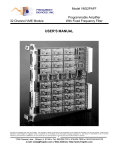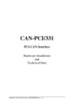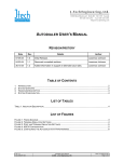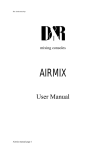
1
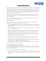
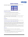
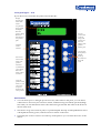
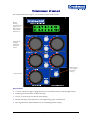
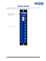
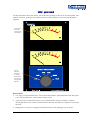
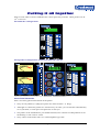
Crookwood R3 Specification guide Everything you need to know about buying an R3 Contents Introduction ............................................................................................................................................................................... 2 What is it, exactly? ................................................................................................................................................................ 2 So you’d like an R3, what options do you need? .................................................................................................................... 2 Example........................................................................................................................................................................... 4 Pricing out the options ..................................................................................................................................................... 4 Electronics ............................................................................................................................................................................ 4 What will your R3 look like?........................................................................................................................................................ 5 Front panel components .................................................................................................................................................. 5 Insert Panels .............................................................................................................................................................................. 6 Description of the record path.......................................................................................................................................... 6 Record Sources ................................................................................................................................................................ 6 Conversion between domains – digital to analogue, and back again ................................................................................. 6 Record inserts.................................................................................................................................................................. 6 Record Destinations ......................................................................................................................................................... 7 MS System ....................................................................................................................................................................... 7 Level Trimmers ................................................................................................................................................................ 8 P&G Fader ........................................................................................................................................................................ 8 Insert panel type 1 – 3AI ....................................................................................................................................................... 9 Panel Features.................................................................................................................................................................. 9 Insert panel type 2 – 7AI ..................................................................................................................................................... 10 Panel Features................................................................................................................................................................ 10 Insert panel type 3 – 11AI ................................................................................................................................................... 11 Panel Features................................................................................................................................................................ 11 Insert panel type 4 – 15AI ................................................................................................................................................... 12 Panel Features................................................................................................................................................................ 12 Trimmer Panel ......................................................................................................................................................................... 13 Panel Features................................................................................................................................................................ 13 Fader panel .............................................................................................................................................................................. 14 VU panel .................................................................................................................................................................................. 15 Panel Features................................................................................................................................................................ 15 Putting it all together ............................................................................................................................................................... 16 General Panel information .............................................................................................................................................. 16 Mounting the panels ................................................................................................................................................................ 17 Connecting the system together............................................................................................................................................... 17 Audio Connections......................................................................................................................................................... 17 Where to go from here ............................................................................................................................................................. 18 Page 1 of 18 Introduction The R3 is the most flexible and powerful analogue mastering or production router available today. It is taken from the routing section of our powerful M class mastering consoles, and can be used in conjunction with one of our C class monitor controllers, or any other model of monitor controller. Unlike other manufacturers, our routers are made from modular components. This means that you can specify your router to have the exact set of features that you need, to fit perfectly into your studio. And as you grow, so can your router. The down side? Because of this advanced modularity, the router is built to order for you, from a set of standard factory options. This takes a bit of time, and you need to be able to specify the options that you need. This manual helps you decide the feature set you want, so you can order your perfect router and start to enjoy all the benefits it will bring you. What is it, exactly? The R3 is a stereo router system designed to allow you to insert various pieces of analogue equipment into an analogue record chain. It has these features: 3, 7, 11 or 15 analogue inserts. You can connect all of your great analogue gear to this central router and simply select what you want to use for a particular session. No more cumbersome manual patching! You control what inserts will be inserted, and in what order in the chain. Inserts can be added, removed or re‐ordered at will. The larger system support full parallel inserts, where a chain can be spilt into two separate chains and recombined at any point with mixing level control. Great for subtle processing. An optional source selector allows you to choose the analogue source for the insert chain. An optional trimmer module allows you to trim input and output levels, either as a separate left and right control, or as a ganged stereo control. A MS module allows you to apply and control MS processing to any number of inserts. All parameters can be stored and recalled from non volatile memory, great for revisions. The router is completely passive and balanced, the trimmers are also essentially passive and balanced, and have a complete relay bypass. As neutral as it gets. It has small, easy to use control panels, and a modular 1U based remote audio rack system You can expand the system as your needs grow. So you’d like an R3, what options do you need? Great, it’s a very good router. Now you need to be able to specify the various options. What you choose will determine how big the front control panels are, how many remote audio racks there are, and of course what it will cost. So let’s start: The R3 is made up of the following 3 parts: The basic insert box. Unlike normal crosspoint routers, the R3 is configured as an insert box, so you can easily insert analogue processing gear into a record path. You can choose the size of the router. Rev 1.0 Page 2 of 18 A source selector. In addition you can add a source selector to allow you to easily select a source for recording. A passive link allows you to send the same set of inputs to an external monitor system, making your wiring easy. Trimmer pack. Finally you can add analogue trimmers to adjust the analogue levels in the record path, and add selective MS processing. This advanced control makes the R3 very quick to use. If you just want combined digital and analogue or just digital routing, look at our R1 and R2 routers. Here are the basic options available for a R3: Inserts Option Analogue inserts (AI) Range Notes 3, 7,11 or 16 You can choose the number of inserts you need. There is no sonic degradation as you add inserts. You will need 7AI or greater for parallel analogue inserts. Range Notes 0, or 1 0SS: no source selector supplied Selector Option Source Selector (SS) 1SS: 4 analogue inputs for record path selection, with parallel output for an external monitor. Trimmers Option Trimmer Pack (TP) Range Notes 0 or 1 You can add trimmers to alter levels in the analogue path. You can fix the position of these trimmers in the insert path, or have them floating, by putting them in an insert. Include in the pack is a MS processor. Fader Option Range Notes 0 or 1 You can add a real 100mm precision P&G stereo fader for doing fade outs. This will normally be wired to the end of the chain, just before the output ADC. Range Notes Crookwood DACs (DA) 0 or 1 We can provide our internal DACs if you wish for linking together the analogue router with external DAWs. Or you can use your own DAC Crookwood ADCs (AD) 0 or 1 We can provide our internal ADCs if you wish for linking together the analogue router with external DAWs. Or you can use your own ADC Range Notes Analogue Fader (AF) Converters Option Physical Option Connectors (CN) 0,X or D Wire to the router D subs yourself (0), use our XLR breakout panels (X) or use our discrete cables (D) Front panel mounting (KT) 0,P or 4 Mount the front panels into your own furniture (0), a movable wooden pod (P) or a 4U 19” frame (4) Rev 1.0 Page 3 of 18 Example The part number for a 7 insert R3 with a source selector, trimmer pack and fader with D subs and a wooden pod would be a: R3‐7AI‐1SS‐1TP‐1AF‐0CN‐PKT Pricing out the options We understand that your budget may not always match your wants, so we have produced a spread sheet that will work out the cost as you change the options. You simply select them from a drop down and the spreadsheet will calculate the exact part number, size, weight and cost of your R3. Electronics Crookwood have been building accurate audio routers and amplifiers since the early 90’s and have a wealth of experience in mastering and production environments. Key features are: Like all our other gear, all signals are completely balanced from input to output. In the trimmer packs there is a one amplifier for the hot phase and an equal amplifier for the cold phase. Expensive, but accurate. The router is completely passive using precision high reliability, sealed telecoms relays. Because it’s a crosspoint router, signals travel through a minimum of relays. Each insert goes through 2 relays, one for the send and one for the return. Other serial type routers require the signal to go through multiple relays even if only one insert is selected. The gain stages are made with a balanced passive relay switched resistor network, followed by a single buffer amp. If you engage all of the electronics in an R3 (2 trimmers and the MS system), the signal will only pass through 4 amplifiers per phase in total. The optional P&G fader is the same type as used in precision consoles, and offers excellent performance. The buffers for this fader run in pseudo‐ balanced as opposed to true balanced – our exception that proves the rule! The system is card based and modular. You can upgrade from a small R3 to a larger one at any point in time. The front control panels remotely control the audio racks. These can be mounted close to the audio gear to minimise wiring. The control panels can be mounted in front of you or in a movable wooden pod that you can move to one side when you’re not using them. Because the front panels are thin, and the racks remote, there is no problem with mounting them into the many desks that have limited front panel equipment depth. Rev 1.0 Page 4 of 18 What will your R3 look like? The configuration of the front control panels depends on your exact specification. Every panel option is detailed, so you can see how easy your configuration is to control. We also detail a few operational notes, so you get a better understanding of how the router works. Front panel components Looking at it in a bit more detail: An R3 basically has 3 front panel components: A insert selector, which selects what devices are inserted, in what order into the record (transfer) path An optional source selector, which selects what you are sending to your external monitor to listen to and what source you are recording from An optional fader pack, which allows you to trim the analogue levels, or apply MS encoding to the analogue path. The panels shown overleaf are 1:1 in size, so you can get an idea of the finished size of your control panel. As a guide, you will have 1 or 2 regular panels, which will consume half of a 4U 19” space. This can leave room for a pair of our precision VU meters and one of our smaller monitor controllers. Rev 1.0 Page 5 of 18 Insert Panels This first panel is what you want a R3 for: it controls what equipment is inserted and in what order into the record path. There are 4 different permutations as follows: Panel Analogue Inserts 3AI 3 7AI 7 11AI 11 15AI 15 The actual panels are detailed further on, but they share some common features. Description of the record path The record path is made up of three simple elements. The elements are: A source replay “tape” machine (the record source), followed by: A set of processing equipment, wired in series, (record inserts), followed by: An output feeding record “tape” machines (record destinations). We use the term “tape” machine, to describe any machine that can replay audio, and/or record audio. Typically this would be a CD. DVD, DAW or MDM. The record inserts are analogue. Converters are needed to go between analogue and digital domains. Record Sources The analogue record source is chosen by our optional selector system. If you don’t have our selector system, just insert an analogue input signal into the router input. Conversion between domains – digital to analogue, and back again Typically you will output the signals from a DAW and after going through the router, the signal will go back into a DAW. To do this well you will need a pair of digital to analogue converters to convert between the two domains. You will need a pair of converters, a (record) ADC and a (record) DAC. They are used as a pair when you insert a set of analogue inserts into a digital path, or just the ADC is used if you have an analogue record source. Crookwood can provide these converters internal to the router, or you can provide your own preferred converters. The Crookwood converters are sonically very good and very cost effective because all of the power supply and infrastructure is already paid for in the audio racks for the router. Record inserts The inserts get inserted between the record source and the record destinations. There are some unique features of Crookwood record insert machines that are really useful, and set us apart from anybody else: We use completely passive, balanced, sealed relays for all analogue routing. Because of this there is no noise or distortion difference between our 3 insert, or 15 insert models. You can decide the permutation of inserts you want for each job. Rev 1.0 Page 6 of 18 You can place the inserts in any order you wish. As you select the inserts with the front panel buttons, the order you select them is the order they get inserted into the chain. You can remove or replace the inserts as you wish. The order of the inserts is shown on the LCD panel, so you always know where you are. You can lock the inserts in place, so that you can remove an insert and replace it back into the same place. You can save a routing chain and level settings to memory and recall it (there are 32 internal stores). This is useful for recalling a session after a break. The larger routers (7 plus inserts) can run their analogue inserts in two parallel paths. Here is an example of a parallel path: This is useful especially for compression work. The top picture shows the system using 2 transfer ADCs. The mixing then will be done digitally in the DAW. The lower picture shows our Trimmer Pack trimmers, A and B being used to mix the signal back together to a single transfer ADC Record Destinations There is one output from the router. Because we use passive routing technology, the last device in the chain is driving this output directly. You can usually connect this output to several other pieces of equipment without worry. This minimised extra electronics in the signal path. If you feel you need to buffer it however, you can simply place a high quality distribution amplifier in series with the output. MS System The Trimmer Pack has 2 level trimmers and an MS system. The MS system comprises an encoder and decoder with an S level control (+/‐ 6dB in 0.25dB steps). This allows you to control stereo width, or perform MS processing to any analogue device or devices. We provide our MS system unpatched – it just appears on the rear panel connectors. This gives you complete control of how to use it. For instance you could: 1. Rev 1.0 Wire the encoder into one insert, and the decoder into another. . Then by selecting the order of the chain, you can insert the MS system around any device or devices you wish. You can also just engage the encoder if you want to output MS encoded signals for any reason. Page 7 of 18 2. Wire the encoder and decoder around one relevant insert. Then use the MS bypass switch to turn the MS system on or off as you require. 3. Hardwire the MS encoder into the start of the chain and put the decoder in an insert. This allows you to MS anything, and process stereo after the MS. This only uses one insert. 4. Hardwire it the other way around, with the encoder in an insert, and the decoder fixed at the end of the chain. You can see the power of this solution. You can decide what topology is right for your studio, rather than being dictated by the manufacturer. As with all Crookwood analogue electronics since the early 90’s, the MS system is fully balanced from input to output and is essentially passive. Precision relays control the mixing and gain elements. Level Trimmers The level trimmers are stepped gain (0.5dB increments) trimmers that have a range of +/‐ 9dB. Separate left and right trimmers are provided so you can trim each channel and there are 2 such trimmers, so you can trim the input and output of the insert chain. In addition each pair of trimmer can be ganged, so you can alter both left and right levels (with a gain offset if required) at the same time. Finally there is a mix mode which allows you to mix the two trimmers together. This is used for mixing together the two parallel paths of a parallel insert system. Here the trimmers must be at the end of the chain for this to work properly. Again they are provided unpatched – all connections just appear on the rear panel connectors. Similar to MS system this allows you to: 1. Wire one trimmer into one insert, and the other trimmer into another. Then by selecting the order of the chain, you can insert a trimmer before or after any insert you choose. You could force this to be an input and output trimmer if you wish, or not. The choice is yours. 2. Hardwire one trimmer into the start of the chain, and hardwire the other at the end of the chain. This gives you a traditional input and output trimmer system. Use the bypass switches to turn the trimmers on or off as you require. 3. Hardwire one trimmer into the start of the chain and put the other trimmer in an insert. This allows you to do input /output trimming, or selective trimmer, while only using one insert. 4. Wire it the other way around, with a trimmer at the end of the chain. Once again our system is immensely flexible. You decide what you want. Again they are fully balanced, relay based stepped designs. Relays passively attenuate the signal and a precision buffer amplifier then buffers this signal for the outside world. P&G Fader This is a real fader, made by probably the best fader company on the planet. Nuff said!. Rev 1.0 Page 8 of 18 Insert panel type 1 – 3AI If you choose a 3 insert R3, the panel will look like this: Display showing the order of the inserts: Sontec – STC ‐ vari Mu Accesses system menu for preset storage and recall. It also stores the settings of the optional trimmer pack Optional source selectors. Not used in the 3 insert panel Inserts and removes the inserts into position. Our label system allows you to easily label each insert with its real name Locks the position of the inserts, so you can remove an replace them into the same position Panel Features You can insert up to 3 analogue processors in any order. The order you click the buttons is the order the inserts get inserted. The order of the inserts in shown in the LCD. The insert lock button locks the position of the inserts in place. In this way, you can remove an insert and replace it into the same position. Optionally the 4 source selectors are at the top of the panel so you can select the source of the inserts. There are lots of spare buttons on this panel. This allows you to easily upgrade to a 7,11, or 15 insert system. We just send you the extra racks and new software – easy! Rev 1.0 Page 9 of 18 Insert panel type 2 – 7AI If you choose a 7 insert R3, the panel will look like this: Display showing the order of the inserts. A represents the A path, B the B path. Here the path splits after insert 2 (MS decode) Accesses system menu for preset storage and recall. It also stores the settings of the optional trimmer pack Optional source selectors. Used to select which path (A or B) the inserts go into. The LCD shows the result Inserts and removes the inserts into position. Our label system allows you to easily label each insert with its real name Locks the position of the inserts, so you can remove an replace them into the same position Panel Features You can insert up to 7 analogue processors in any order. The order you click the buttons is the order the inserts get inserted. The order of the inserts in shown in the LCD. The inserts can go into a main A path, or a parallel B path. The Opt A and Opt B buttons select which path the inserts go into, and all actions are shown on the LCD. Optionally the 4 source selectors are at the top of the panel so you can select the source of the inserts. The spare buttons on the panel allows you to easily upgrade to a 11, or 15 insert system. We just send you the extra racks and new software – easy! Rev 1.0 Page 10 of 18 Insert panel type 3 – 11AI If you choose an 11 insert R3, the panel will look like this: Display showing the order of the inserts. A represents the A path, B the B path. Here the sontec is being MS’d and theVari Mu is in a parallel path. Accesses system menu for preset storage and recall. It also stores the settings of the optional trimmer pack Optional source selectors. Used to select which path (A or B) the inserts go into. The LCD shows the result Inserts and removes the inserts into position. Our label system allows you to easily label each insert with its real name Locks the position of the inserts, so you can remove an replace them into the same position Panel Features You can insert up to 11 analogue processors in any order. More to the point, you can choose what inserts to use from your extensive arsenal, without having to manually patch anything! The order you click the buttons is the order the inserts get inserted. The order of the inserts in shown in the LCD. The inserts can go into a main A path, or a parallel B path. The Opt A and Opt B buttons select which path the inserts go into, and all actions are shown on the LCD. Optionally the 4 source selectors are at the top of the panel so you can select the source of the inserts. Rev 1.0 Page 11 of 18 Insert panel type 4 – 15AI The big daddy! With 15 analogue inserts, the panel looks like this: Display showing the order of the inserts. Optional source selection, define by system menu Here the order is: Trimmer A MS Encoder Vari Mu MS Decoder Sontec Trimmer B Accesses system menu for preset storage and recall. It also stores the settings of the optional trimmer pack Used to select which path (A or B) the inserts go into. The LCD shows the result Inserts and removes the inserts into position. Our label system allows you to easily label each insert with its real name Locks the position of the inserts, so you can remove an replace them into the same position Panel Features You can insert up to 15 analogue processors in any order. More to the point, you can choose the exact inserts you want to use from your treasured collection, without having to manually patch anything! The order you click the buttons is the order the inserts get inserted. The order of the inserts in shown in the LCD. The inserts can go into a main A path, or a parallel B path. The Opt A and Opt B buttons select which path the inserts go into, and all actions are shown on the LCD. You only need to use the B path when you require it. Optionally you can choose an input from 4 sources. The system menu accesses the sources, rather than discrete buttons. Not a big deal, as you don’t need to change them very often. Rev 1.0 Page 12 of 18 Trimmer Panel The optional trimmer pack gives you 2 trimmers, plus an MS system: Display showing accurate left and right levels in dB of trimmers A&B, and the MS level in % Gangs the left and right together for stereo level control Makes B mix to A for parallel insert path mixing Controls the MS Panel Features You can control left, right or ganged levels for each trimmer (stereo with left/right offsets) Hard bypass the trimmers, or MS with relays Precise, accurate levels are shown in the display Double the range of the trimmers if you require large gains or attenuation. Mix together the A and B trimmers for re‐combining parallel routing Rev 1.0 Page 13 of 18 Fader panel This optional panel allows you accurately fade out your analogue path. Usually this is done in the DAW, but if you wanted an accurate analogue fade, you can now have it! Same height panel as the rest of our panels, so it fits into the same mounting options. High quality P&G 100mm fader Rev 1.0 Page 14 of 18 VU panel Crookwood make 2 Stereo VU meters, one in the same package as the rest of our front panels, and another in a 2U 19” package. The trimmer pack has a meter output so you can meter the path if required. Large Sifam VU meter, with accurate VU ballistics Passive, balanced attenuator, accurately drops level to VUs without altering their ballistics Panel Features Two large, accurate Sifam meters, with accurate VU ballistics. Quite different to the cheap VUs you see everywhere else, ‐ these meters actually work! A precision passive attenuator allows you to run the meters with your masters, without driving the meters into overload. The attenuator does not affect the VU’s ballistics as you alter the level. Being passive, no power is required to make the meter work, making it easy to install. Rev 1.0 Page 15 of 18 Putting it all together Here are some ideas of what a finished router control panel may look like. These pictures are all 1/3rd of real size. The smallest R3- 3 analogue inserts. The largest R3- 15 analogue inserts, trimmer pack, P&G fader , plus VUs. General Panel information Here’s a bit more general information on the panels: They are only 30mm (1.5”)deep (except the VU which is 75mm – 3” deep) Although we connect the panels in a certain factory set order, you can alter the order that they sit on your desk, or even space each panel out as suits you The panels can be mounted into your studio furniture, into a mobile wooden pod that sits on the desktop, or into a 4U 19” frame. They connect to the audio racks via a small telephone type cable Rev 1.0 Page 16 of 18 This cable is typically 5M (18ft) long, but can be made longer or shorter to suit. The audio racks that do all of the audio work, are also modular, but because they are just black boxes, they can be placed anywhere convenient to minimise your studio wiring. The legends for the panel switches are user changeable. They are printed onto paper, and we can provide a simple template for you to label them as suits you. Mounting the panels There are 3 options for mounting the controllers: In a 4U 19” rack system. Up to 4 standard panels fit into a 4U rack In a moveable wooden pod. The pod is made of stained English ash. Directly into your own studio furniture. The front panels have lips on their edges so they can be easily mounted into your own studio furniture. Connecting the system together While the panels control the audio, the actual processing is done in several 1U racks that can be mounted remotely. The actual number of racks will depend on the exact feature set, but it varies from 1 to 3 racks in total. As standard a 5M (18ft) cable is supplied to link the front panel to the racks. This can be extended if required however. Audio Connections All of the audio connections are made to the rear of the racks via DB25 multiway connectors. These connectors are all pinned out to the industry standard pinout. Why Dsubs? Well partly because of the number of connections – a fully featured router would need about 7U of XLR patch space, rather than the 4U of actual rack space. The Dsub is also a very good connector, and with modern cables it’s quite easy to wire up to. There are a few ways to wire up the audio to your router: Rev 1.0 Page 17 of 18 Purchase ready made cables from your local music shop. The standard pinout means many manufacturers make these cables. Purchase XLR breakout cables from us. We can make them to a variety of lengths. Wire up to the D Subs yourself. Either wire directly to the equipment, or to an intermediary patch if required. Purchase our XLR breakout patchbays. These are 1U bays with 16 XLRs on them, labelled appropriately with the connector function. They are typically mounted within 0.5M (18”) of the rack rear panels. Where to go from here Now you have an idea of what it is you want, please ask us for a quote, or a copy of the specification spreadsheet which will allow you to calculate the prices as you alter the spec. You may also like to look at: R3 installation manual R3 user manual At any point in the process, please feel free to call us for advice. Our details are: Crookwood 239, East Grafton Marlborough Wiltshire, SN8 3DF England Tel: +44 (0) 1672 811 649 Fax: +44 (0)1672 811 650 Email: [email protected] Web: www.crookwood.com We look forwards to hearing from you. Rev 1.0 Page 18 of 18