1
142 SIERRA ST., EL SEGUNDO, CA 90245 USA (310)322-2136 FAX (310)322-8127 www.ESE-WEB.com
ES-102 GPS BASED
TIME CODE GENERATOR / MASTER CLOCK
OPERATION AND MAINTENANCE MANUAL
The ES-102 is a GPS Master Clock/Time Code Generator. The unit receives accurate time and date information from
Global Positioning System satellites and supplies this data to the user in the form of four (4) different types of time
code (SMPTE/EBU, ASCII, TC89 and TC90) and a front panel six-digit display (.56” yellow LEDs). Two (2) One Pulse
Per Second outputs and a GPS “Lock” output are also available. A twelve-channel receiver is employed that is
capable of tracking up to twelve (12) satellites simultaneously, although reception of only one is required for time data
to be output.
Several options are available that allow the unit to meet most any requirement asked from a Master Clock or Time
Code Generator. These options are described in the “OPTIONS” section.
INSTALLATION & OPERATION
The basic installation of the ES-102 is nearly as simple as connecting the Antenna Cable and 117 VAC to the unit,
and allowing the unit to "lock" onto GPS. However, after any "bench" testing is complete, the most important concern
is to mount the Antenna and route the cable according to the instructions provided on page 7.
All other connections between the ES-102 and other equipment should be made by a qualified technician or engineer.
The technician or engineer should be familiar with each piece of equipment being interfaced with the ES-102. Please
refer to the descriptions and specifications for details concerning the various Standard Features, Setup Features and
Options. Consult the manufacturer of the equipment or the ESE factory if assistance is required.
A lithium coin cell battery maintains the settings of the GPS receiver during periods without power. The battery is
capable of maintaining the settings for up to four years. If the receiver needs re-initialization, refer to the master clock
software program descriptions on page 11.
STANDARD FEATURES
Power Supply
The ES-102 is equipped with an internal Power Supply. The Power Supply requires 117 VAC via the 3-wire line cord.
Display
The front-panel contains a single green LED that indicates if the unit is "Locked" to GPS. When locked to GPS, the
LED remains lit. Prior to lock or when lock is lost, the LED blinks at a 1 Hz rate. The ES-102 also has a six-digit .56”
high yellow LED display.
Outputs
The rear-panel of the ES-102 provides access to the time codes, 1PPS and GPS Lock outputs via XLR, BNC and
DB-9 connectors. Please refer to the "Rear Panel DB-9 Connector Pin Designations" and "Specifications" for more
details.
EBU: The ES-102 can have an EBU Time Code output specified. The EBU Time Code Output is accessible
via an XLR connector. Accuracy of the EBU is +/- 400 mS and can be synchronized to a video source
via the "Video In" BNC connector. The EBU time code is automatically “re-synched” to GPS at
2:00:00 AM. EBU (European Broadcasting Union) is used predominantly in Europe in the TV, Cable
and Video industries.
SMPTE: The ES-102 can have a SMPTE Time Code output specified. The SMPTE Time Code Output is
accessible via an XLR connector. Accuracy of the SMPTE is +/- 400 mS and can be synchronized to
a video source via the "Video In" BNC connector. The SMPTE time code is automatically “resynched” to GPS at 2:00:00 AM. SMPTE (Society of Motion Picture and Television Engineers) is
used predominantly in the TV, Cable and Video industries. The SMPTE User Bits are, from high to
low, as follows: 1OY-X-Y-X-10M/10D-M-D-X. When Julian Day of Year is used, the SMPTE User Bits
are as follows: X-X-X-X-X-100D-10D-D.
Drop Frame: Unless otherwise specified, the unit is set to provide "Drop Frame" SMPTE Time Code. If
non-Drop Frame SMPTE is desired, turn “ON” the “NDF” DIP switch (switch #7 on the
ES-101 logic board).
Page 1 of 22
Page 2
Date: The date information encoded into the "user bits" of the SMPTE time code is typically set to
include Month-Day-Year information. Turning “ON” the "DOY" DIP switch (switch #5 on the
ES-101 logic board) reformats the data to contain Day of Year (001-366) instead of MonthDay-Year.
ESE Time Code: The most efficient and cost-effective method for time code distribution in a Master
Clock/Remote Clock System employs the ESE Time Code output. ESE Time Code is
capable of driving up to 100 remote displays at a distance of up to 4000 feet. Connections
(between the ES-102 ESE Time Code Output and any ESE Time Code Reader) can be
made using twisted pair wire or coax cable such as RG-58 or RG-59. The accuracy is 17mS
of UTC and the time code is accessible on two separate BNC connectors (TC89 & TC90).
TC89 is an older version of ESE Time Code and should be used to drive older ESE Time
Code Readers (non-”A” versions). TC90 contains “Date” information as well as time data
and should be used if “Date” is to be displayed on the Reader.
RS-232C: RS-232C ASCII Time Code is used to interface with a PC or other computer system. The
ASCII transmission contains date and time data and is transmitted once per second. The
data is accessible on the DB-9 connector. Windows and DOS software included with the
unit enables the ES-102 to continuously update a computer’s clock. (Software is also
available from the ESE Web-Site at http://www.ESE-WEB.com.)
GPS “Lock”: Access to a TTL output of GPS "Lock" information is accessible on the DB-9 connector.
When locked the signal goes to a logic “1”.
1PPS: The most accurate time information available from the ES-102 is that provided by the
1PPS Output (one pulse per second). Two (2) outputs are provided: a 20% duty signal
specified as being within 500ns of UTC, and a 50% duty signal which is within 1mS of UTC.
The 20% duty signal is obtained directly from the receiver. The 50% duty signal is
regenerated by the timekeeping microprocessor; this signal is isolated from dropouts due to
signal loss and should be used for long-term timekeeping purposes. Both signals are
positive edge true. The 1PPS can be used for synchronization purposes in a variety of
applications. One such application allows the 1PPS to drive an Impulse Driver (ES-165 or
ES-162A) which, in turn, can drive "Analog" Impulse Clocks (ES-168 or ES-162S).
Battery
The ES-102 has a lithium coin cell battery that maintains certain receiver configuration settings during power outages,
storage or shipment. The battery is capable of maintaining these settings for up to four years. All outputs, however,
are suspended during a power outage. If continuous outputs during power outages are required, a UPS
(Uninterruptable Power Supply) is suggested. Option “BBU” is available and is capable of maintaining power to all
outputs during a power outage for up to four hours.
Antenna
An "active" GPS Antenna (1.575 GHz) with 16’ 5” cable is supplied with the ES-102 and connects to the unit via a
TNC connector. ESE has conducted a series of tests with the purpose of determining a maximum cable length (with
or without amplification). A summary of the tests and the alternatives are discussed on page 8. Proper installation of
the antenna module is imperative for proper operation and continued life of the antenna and clock. See page 7.
Enclosure
The ES-102 is housed in a rack-mount enclosure that measures 1.75" high x 19" wide x 9.5" deep (plus connectors).
The ruggedized enclosure is constructed of etched and clear anodized aluminum.
SETUP FEATURES
Several features of the ES-102 are factory set according to information supplied by the end user or according to
factory standards. All Setup Features are selected via DIP switches except "Time Zone", "Time Delay/Advance" and
"Cable Delay". All Setup Features are discussed below.
Time Zone: The ES-102 receives GPS time and date information which has been encoded and set to UTC
(Universal Coordinated Time/Greenwich Mean Time). The unit must be set at the factory to decode
and output time for the end-user's time zone. Or, by using the software supplied with the ES-102,
the time-zone can be changed "in the field". This is accomplished by connecting the RS-232C input
to a computer serial port and running the ESEGPS (Windows) or GPSINI.EXE (DOS) programs.
Running GPSINI.EXE without command line switches will print the instructions on screen. Run the
GPSINI.EXE program again using the appropriate command line parameters. Please connect
ONLY the 2 data lines & the ground line to the computer: the DB-9 connector also provides access
Page 3
to unrelated functions which should not be connected to the computer. (Software is also available
from the ESE Web-Site at http://www.ESE-WEB.com.)
12/24 Hr: The ESE “TC89” Time Code can be output in either 12 hour or 24 hour format. This enables
Remote Clocks to differ from the Master. Turn “ON” the “24 HR” DIP switch (switch #4 on the ES101 logic board) for 24 hour operation. Note: Most ESE Serial Time Code Reader Clocks can be
programmed for either 12 hour or 24 hour format regardless of the “TC89” format. To set the
display for 12 hour format, turn on DIP switch #4 on the ES-USS display logic board.
DST: DST (Daylight Savings Time) can automatically be compensated for if the end-user desires.
Turning “ON” the "DST" DIP switch (switch #6 on the ES-101 logic board) enables the DST feature.
The DST adjustment is according to the standards used in the United States and switches at 2:00
AM. Foreign DST standards are available on a "custom" basis.
Date: The date information encoded into the SMPTE time code is typically set to include Month-Day-Year
information. Turning “ON” the “DOY” DIP switch (switch #5 on the ES-101 logic board) reformats
the data to contain Day of Year (001-366) instead of Month-Day-Year.
OPTIONS
The rear-panel of the ES-102 provides access to all "Optional" inputs and outputs via various connectors (BNC &
DB-9). Please refer to the "Rear Panel DB-9 Connector Pin Designations" and "Specifications" for more details.
Time Codes
B: Option "B" provides a parallel BCD Output of the time data. The data is CMOS compatible and
contains 20 Data Lines (10’s Hours thru Seconds) and Ground. Applications requiring Parallel BCD
require an ES-169B (Serial To Parallel Time Code Converter) to be ordered separately.
Frequency Outputs
K: Option "K" provides a 1 KHz square wave, a 10 MHz sine wave and a phase coherent 1 PPS output.
The 1 PPS output has a 50% duty cycle and replaces the standard 50% duty cycle 1 PPS output. The
1 KHz and 10 MHz outputs are accessible on BNC connectors. The sine wave is 4 Vpp into 50 ohms.
Potentiometer R6 allows the output level of the sine wave to be adjusted by +/- 0.5 volts. The square
wave is 5 Vpp. A front panel 10 MHz Lock LED is provided. This LED lights solid to indicate that the
unit has “locked” to GPS and the outputs are within specifications. The 1 PPS output is phase
coherent when the 10 MHz Lock LED lights solid. The LED blinks if GPS “lock” has been obtained,
but the outputs are out of specifications. If “lock” has not been obtained, the LED does not light.
Option ‘45ηS’ is required.
The Option “K” system functions independently from the rest of the clock, although it receives its
input from the same GPS receiver as the clock system. When first powered up, the receiver searches
for satellites. When it locks on to at least one, the GPS Lock LED indicates a locked condition by
lighting solidly. The 10 MHz Lock LED begins flashing after a delay of about 40 seconds. The flashing
of this LED indicates that the GPS receiver is locked and that the 10 MHz system is in the process of
adjusting the frequency of the 10 MHz output. This process may take up to 1 hour. During this time
the frequency, if measured, may indicate 100 – 200 Hz off. This is normal during the locking process.
While the 10 MHz Lock LED is flashing, the output should not be used as a reference. When this LED
lights solidly, the output is within tolerance.
The ES-110M12 PCB generates the Option “K” outputs – 10 MHz & 1 KHz. The PCB receives 1 Hz
and satellite data from the GPS receiver on the main PCB. +12v & +5v power is also supplied to the
110M12 board. The system consists of a TCXO (temperature-compensated crystal oscillator), counter
chain, phase detector, loop filter and supervisory microcontroller (Z2). The 20 MHz oscillator is
divided by the counter chain (Z7-Z12 & part of Z5) down to 1 Hz. The phase-detector chip (Z4)
receives this signal and the 1 Hz signal from the GPS receiver. Z4 produces an output which is fed to
the loop filter, consisting of analog switch Z3, resistors R15 - R17, capacitors C22 - C23 and op-amp
Z17. The analog switch allows the microcontroller to control the time constant of the filter and also
disable the loop during periods of non-reception of satellites. The filtered control voltage is fed to the
frequency control input of the TCXO. This functions as a phase locked loop, controlling the frequency
and phase of the oscillator from the GPS reference 1 Hz. The satellite data from the GPS is fed to the
microcontroller UART input, allowing the system to know if the receiver is locked to satellites. The
microcontroller also monitors an output from the phase detector chip to determine the amount of
phase difference between the GPS and the internally divided 1Hz. If it is greater than approximately
40 milliseconds, the microcontroller “gear shifts” the counter chain fast or slow to bring the relative
phase to under 40 mS. This procedure is performed during initial lock-on, or if reception of satellites is
lost for a significant time and enough drift occurs. After rough phase adjustment is performed, the
oscillator frequency remains either fast or slow by about 100-200 Hz until the local 1 Hz arrives in
Page 4
phase with the GPS 1 Hz. This typically takes up to 1 hour. During this time, the 10 MHz Lock LED
flashes. The frequency then stabilizes at the center frequency of 20 MHz (it is divided by 2 for the
output). After stabilization, the 10 MHz Lock LED lights solidly. The 10 MHz output is filtered to a
sine-wave and buffered by op-amp Z14. The microcontroller generates the 1 KHz signal, which is
buffered by Z1.
HR: Option "Hr" provides a relay contact closure on the Hour and on the Half-Hour. An internal DIP switch
(switch #3 on the ES-101 logic board) can be turned “ON” if a closure on the Hour ONLY is required
(Hr & 1/2 Hr is supplied unless otherwise specified). The reed relay is rated at 10 watts maximum
resistive load (500mA switching current) and is intended for control applications only. Relay contacts
are accessible on the DB-9 connector.
Miscellaneous
ANT: A high performance antenna for challenging EMI environments is provided with this option. Nineteen
feet of cable is supplied with the antenna.
BBU: The ES-102 can be ordered with built-in Battery Back-Up/Charger System. Option ‘P’ is required. The
battery is capable of maintaining the time code outputs during a power outage for up to 4 hours.
Displays, if ordered are blank during a power outage. If continuous displays during power outages are
required, a UPS (Uninterruptable Power Supply) is suggested. Note: Turn off the battery during
shipment or any extended periods of time without main power.
DC: The ES-102 can be ordered from the factory to operate exclusively from a DC source. The voltage
applied must be in the range from +12 VDC to +36 VDC. A 2 amp fuse is provided.
J: The standard ES-102 is intended to operate from 117 VAC 50/60 Hz. If 220 VAC operation is
required, Option "J" must be specified.
UL: When Option “UL” is specified, the unit’s power transformer is external to the unit, ie: a “wall wart”
type UL/CSA approved transformer is supplied. This option allows the ES-102 to be installed in
facilities requiring “UL” (or equivalent) approved equipment.
45η
η S: The ES-102 can be ordered with improved accuracy. When so specified, the unit delivers a 1PPS
accuracy of <45ηS. Also, when the 45η
η S option is specified, two (2) additional Setup Features are
available and are described below.
Time Delay: This program allows the ES-102 to provide an advanced or delayed time output. Time
can be adjusted +/-400mS. Refer to the "readme.txt" file on the provided CD for more
details.
Cable Delay: This program allows the ES-102 to compensate for antenna cable delay, adjustable for
0 - 22,215 feet. Refer to the "readme.txt" file on the provided CD for more details.
Page 5
GPS RECEIVER:
1 PPS OUTPUTS:
ESE TC OUTPUT:
SMPTE/EBU TC OUTPUT:
RS-232C OUTPUT:
RS-232C FORMAT:
VIDEO INPUT:
ACCURACY:
DRIFT:
POWER:
MECHANICAL:
OPTION K:
SPECIFICATIONS
Motorola 12-channel
DB-9 connector, TTL outputs, positive edge true:
#1 - 20% duty output <500nS accuracy, directly from receiver
#2 - 50% duty output < 1mS accuracy, regenerated
BNC, drives 100 readers, 4000' cable maximum
TC89 - drives non-”A” version Readers
TC90 - drives “Date” Readers and/or “A” version Readers
XLR, 600Ω balanced or unbalanced
DB-9 connector, ASCII Date & Time, sent once per second
ESE Format “A”
ASCII @ 9600 Baud, 8 Data, No Parity, 1 Stop
MM-DD-YY<SPACE><SPACE>DDD:HH:MM:SS<CR>
Transmission is once per second and ends 7 mS before Time True.
BNC, RS-170 composite video / blackburst, 1 VPP, 75Ω
1PPS @ < 500nS
ESE TC @ 17mS
SMPTE/EBU @ 0 frames with respect to video sync, +/- 400 mS if free running (due
to Drop Frame compensation)
33mS/Day
117 VAC, 50/60 Hz, 15 Watts typical
Rack Mount Enclosure 1.75” H x 19" W x 9.5” D (plus connectors)
10 MHz Sine wave, BNC, 4 Vpp into 50 ohms (adjustable +/- 0.5V)
1 KHz Square wave, BNC, 5 Vpp CMOS/TTL
1 PPS, 50% duty cycle, DB-9 (pin 5), 5 Vpp CMOS/TTL, < 2 µS of GPS when 10 MHz
lock LED is solid
REAR PANEL DB-9 CONNECTOR PIN DESIGNATIONS
Pin
1
2
3
4
5
6
7
8
9
ES-101 Logic Board
Switch
1
2
3
4
5
6
7
8
Function
+12 VDC - +36 VDC Input (option “DC” only)
RS-232 TXD
RS-232 RXD
1 PPS (20 % duty)
1 PPS (50 % duty)
Relay (Hr opt)
Relay (Hr opt)
GPS Lock
Ground
DIP SWITCH SETTINGS
ES-USS Logic Board (Display Logic Board)
Function (if switch is “ON”)
Mode (see table below)
Mode (see table below)
Relay Closure on the Hour only
TC89 24HR output
DOY output
Daylight Savings On
Non-Drop Frame
Not Used
Switch
1
2
3
4
5
6
7
8
ES-101 Logic Board Mode Switches
Mode
IRIG-B
IRIG-E
SMPTE
EBU
Switch 1
OFF
OFF
ON
ON
Switch 2
OFF
ON
OFF
ON
Function (if switch is “ON”)
Date
Not Used
Not Used
12 Hour Format
9 Digit Display
Not Used
Not Used
Not Used
Page 6
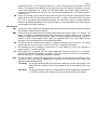
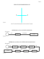
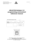
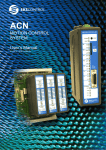
TEMPLATE FOR ANTENNA/MOUNTING PLATE
Figure 1.
Note: The Antenna Mounting Plate can also be used as a Template.
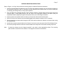
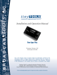
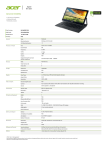
ANTENNA With LA-12F And 150' Of EXTRA CABLE (RG-58)
GPS Antenna
16’ 5”
150’ (RG-58)
LA-12F
ES-102
Figure 2.
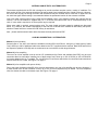
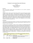
ANTENNA With 5) LA-12FN And 500' Of EXTRA CABLE (RG-8) With ES-AB1A
GPS Antenna
16’ 5”
100’
LA-12FN
2’
ES-102
Figure 3.
100’
LA-12FN
100’
ES-AB1A
100’
LA-12FN
100’
LA-12FN
LA-12FN
Page 7
ANTENNA MOUNTING INSTRUCTIONS
Refer to Figure 1 on Page 6 and perform the following steps to install the Direct Mount Antenna.
1. Locate a spot that allows the Antenna a view of the sky and where the antenna can be mounted according to
the instructions that follow. Note: It is advised to test the Antenna at the location where it is to be mounted prior
to mounting (and drilling holes) to verify proper operation.
2. Two 1/8” holes on the mounting plate are used to mount the antenna. Two #4 screws can be used to secure the
mounting plate. If using plastic anchors, drill two holes of the appropriate diameter and depth (using the
template provided on page 6) through the deck plane where you are mounting the antenna.
3. Press into each hole a plastic anchor until the top of the anchor is flush with the deck plane.
4. Drill a 5/8" hole (for the antenna connector/cable) slightly below where the antenna is to be mounted.
5. Route the antenna connector/cable through the 5/8" hole and then fasten the Antenna to the deck plane using
two (2) #4 screws.
6. Connect the antenna connector/cable to the "Antenna" connector on the rear panel of the ES-102 Master Clock.
7. Fill the hole (through which the antenna connector/cable was routed) with an all-weather caulking compound.
Note:
If desired, the Antenna can be "magnet mounted" to any steel or other appropriate surface. The mounting
plate should be removed from the Antenna. The magnet is mounted to the Antenna.
Page 8
ANTENNA CABLE TESTS & ALTERNATIVES
The antenna supplied with the ES-102 is designed to provide excellent reception under a variety of conditions. For
best results, the top of the antenna should have at least a partial view (unobstructed line of sight) of the sky. However,
the view of the sky may be through a window and the antenna may be mounted indoors if the roof or upper floors do
not shield the signal. Bench testing is recommended before the permanent location for the antenna is decided.
One of the main concerns when using a GPS receiver (Master Clock) is the distance between the antenna and the
receiver. The ES-102 Antenna is supplied with 16’ 5” of RG-58 coax cable which can be connected directly to the
clock. If more cable is required an in-line amplifier may be required.
When extra cable is required, several options exist. The most simple and least expensive methods are discussed
below. It is, however, the ultimate responsibility of the end-user to decide which method will best satisfy the specific
situation. Please feel free to contact the ESE factory for assistance.
Also... please read the section below which discusses the tests performed at ESE.
CABLING SUGGESTIONS / ALTERNATIVES
Method 1 (low loss cable)
Several types of "low loss" coax cable are available including RG-8 and RG-213. Using any of these types of cable
"may" allow up to 300' of additional cable to be added to the 16’ 5” supplied with the antenna. Both RG-8 and RG-213
are expensive (relative to RG-58) and are cumbersome to work with due to their larger diameter.
Method 2 (in-line amplifier)
The use of an in-line amplifier such as the LA-12F (manufactured by Raven and available from ESE) may be more
convenient than low loss cable. Installing one of these amps "may" allow up to 150' of RG-58 (or 300' of RG-8/RG213) to be added to the 16’ 5” supplied. The LA-12FN has 'N' connectors which allow for convenient interconnections
with RG-8 and RG-213 cable. See Figure 2 on page 6.
Method 3 (in-line amplifiers with power divider)
Due to the power limitations of the ES-102's receiver and antenna, only one in-line amplifier can be used. However, if
a power divider such as the ES-AB1A is used, up to five (5) in-line amplifiers may be added. The more amplifiers
used, the shorter the cable run between amps. See Figure 3 on page 6.
Page 9
ESE TEST RESULTS
The methods mentioned above are conclusions based upon actual tests performed by ESE and on information
provided by various manufacturers. The performance of your unit may differ due to antenna position and obstructions
to its line of sight, weather/atmospheric conditions, cable length or signal reflections.
Listed below are the best consistent and repeatable performances. That is, they were repeatable performances on a
consistent basis... not just fluke observations.
Caution is recommended: as the GPS Satellites age, their signal strength may decrease and today's cable length
could cause undesirable results at a later date.
The ESE factory conducted several tests which demonstrate how the ES-102’s Antenna can be expected to operate
for given sets of circumstances. All tests were conducted at ESE (in El Segundo, CA) in 1998 and due to the
architecture of the GPS Satellite Constellation, can be considered applicable most anywhere in the world.
Test 1
The first test shows that up to 112' of RG-58 cable can be added to the 16’ 5” without any significant loss in signal.
(Adding 125' impaired the clock's performance.)
Test 2
When using a single LA-12F, in-line amplifier with 150' of RG-58 cable (in addition to the 16’ 5” supplied), the clock
would "lock-on" in a nominal amount of time. (Adding 175' impaired the clock's performance.)
Test 3
Using an ES-AB1A (power divider) and two (2) LA-12F with 100' of RG-58 cable attached to each (216’ 5” total)
permitted the clock to "lock-on" in a nominal amount of time. Adding a third LA-12F with 75' of RG-58 cable did not
impair the clock's performance, however, increasing the 75' to 100' did impair the clock's performance.
Test 4
Using an ES-AB1A (power divider) and four (4) LA-12F with 75' of RG-58 cable attached to each (316’ 5” total)
permitted the clock to "lock-on" in a nominal amount of time. Adding a fifth LA-12F with 25’ of RG-58 cable also
permitted the clock to “lock-on” in a nominal amount of time. Increasing the 25’ to 50’ impaired the clock’s
performance.
All of the tests mentioned above were conducted twice; first with the antenna indoors and second with the antenna
outdoors. (Indoors refers to the ESE factory which is a single story building with a wood ceiling and asphalt composite
roofing. And outdoors, the antenna had a very narrow look at the sky with approximately six feet of clearing between
one-story buildings.)
In all cases, the ES-102 "Locked-on" within fifteen minutes, and in less time when the antenna was outside. ("Lockedon" refers to starting the clock from a completely "powered down" mode and the ESE Time Code output "catching"
real-time with the "GPS Lock" LED lit.)
Various tests conducted away from the factory show that the exact unit which took five minutes to lock-on at the
factory, may take up to 45 minutes at a different location. Possible explanations for this phenomenon lead us to
believe that atmospheric conditions or poor antenna locations may be responsible.
Page 10
APPLICATION NOTES
Application Note 1
ESE has noticed that the manufacturers' cable length specifications for the Motorola GPS Receiver and the Raven
LA-12F differ from the test results of ESE. Please be aware that Motorola specs the maximum cable distance
between the antenna and the receiver is 16’ 5” (5 meters) without amplification. Also, please be aware that Raven
specs the maximum RG-58 cable that the LA-12F can drive is 50 feet.
ESE's test results may indicate that longer lengths of cable may be used. We are not inferring that the longer cable
lengths should be used. We are only reporting the results of our tests and repeat the caution mentioned earlier.
Caution is recommended:
as the GPS Satellites age, their signal strength may decrease and excessive cable length may cause undesirable
results.
Application Note 2
All ESE tests were conducted using RG-58 coax cable. According to several manufacturers of low loss cable, the
signal loss attributable to cable length can be reduced with the use of "low loss" cable. According to the RG-8 and
RG-213 cable specifications, when compared to RG-58, cable lengths may be doubled or more with "equal to" or
"better than" results.
Application Note 3
Once an ES-102 has "Locked-on", the receiver creates a semi-permanent "Library" of where it expects to "see" a
satellite(s) at a specific point in time. However, if after "Locking-on", the unit is relocated (for instance, from the ESE
factory in California to an end-user's site in Europe), the unit's 1 PPS (and other outputs') accuracy may appear erratic
for up to three hours. When the receiver has created an updated Library, all outputs will then comply with the
specifications discussed in this manual.
Page 11
MASTER CLOCK SOFTWARE - Program Descriptions
The ES-102 is shipped with a CD that contains several "Setup" Programs. Some of those programs are discussed
below. All programs are described in the "Readme" file. It is suggested that one refer to the "Readme" file as it may
contain updates issued after this manual was published. This software is also available from our web-site at
"www.ESE-WEB.com". The DOS programs described below do not need to be used if the Windows programs are
used. For Win 3.1, use the "16 Bit" programs. For Win 95/98/ME/NT/2000, use the "32 Bit" programs. The DOS
programs are in the form of separate command-line utilities. For the Windows versions, run the Setup.exe program.
After the Install Wizard runs, a shortcut to the executable file will appear in your Start Menu.
ESEGPS
This Windows program synchronizes the computer system time to the Master Clock time, and provides a control
panel for adjusting various Master Clock functions. This program may be used to reinitialize the receiver if necessary.
This program opens as a "watch" icon in the System Tray. Click on this icon to open the Control Panel applet.
MASTER32
This Windows program works with the ASCII time output (Format "A", "0" or "1"). It synchronizes the computer
system time to the Master Clock time. This program opens as a "watch" icon in the System Tray. Click on this icon to
open the Control Panel applet.
MCDOS.EXE
This DOS program will set the System Time and Date of a PC/Compatible computer from an ES-102 GPS Master
Clock when the machine is booted up. The line "MCDOS" should be added to your AUTOEXEC.BAT file. The file
MCDOS.EXE should be placed either in the root directory or where the current PATH can find it.
The program by default is set to use COM1. To set it to a different COM port, add the port number to the command
line:
MCDOS /2
The MCDOS.EXE program may also be invoked from the DOS prompt to set the time whenever desired. If you are
using the optional serial port command described above, you can make running the program easier by creating a
batch file to run the program:
COPY CON:T.BAT <enter>
MCDOS /2 <enter>
F6 (the function key) <enter>
Now, just typing T <enter> will set the time.
GPSINI.EXE
This DOS program is used to initialize the Time Zone, Time Delay and Cable Delay Compensation values. The Time
Delay factor is set to zero, and the Cable Compensation is set for 19 feet. Running the program will print full
instructions on screen for setting the time zone.
GPSHIFT(x).EXE
These DOS programs are used set the ES-102 to provide an advanced or delayed time output. This can be useful in
TV network situations to compensate for video satellite delays. The time is adjustable from 0 to +/- 400 milliseconds,
in increments of 1 millisecond. Determine which COM port you have available and use GPSHIFT1.EXE for COM1:
and GPSHIFT2.EXE for COM2:. To set a 1/4 second delay using COM1:, for example, type GPSHIFT1-250 then hit
the ENTER key.
GPSCBL(x).EXE
These DOS programs are used to compensate for antenna cable delay, adjustable from 0 - 22215 feet. Determine
which COM port you have available and use GPSCBL1.EXE for COM1: and GPSCBL2.EXE for COM2:. To
compensate the unit for 200 feet using COM1:, for example, type GPSCBL1 200 then hit the ENTER key.
NOTE: All of these settings are remembered by the ES-102, even if powered down with the battery off.
GPSTIME.EXE
This DOS program is used to set the Time and Date of the unit in the absence of a satellite signal.
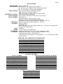
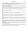
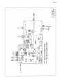
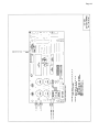
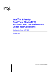
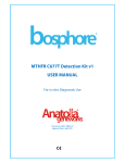
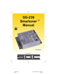
POWER
FUSE
OFF
ON
BATTERY
OUTPUT
SMPTE/EBU
MINUTE
10 MHz
LOCK
GPS
LOCK
RS-232C/
1PPS
TC90
OUTPUT OUTPUT
TC89
The unit is shown with Option K.
SECOND
ES-102
GPS MASTER CLOCK
INPUT
VIDEO IN
10 MHz
OUTPUT OUTPUT
1 KHz
OPTIONAL
ES-102 GPS MASTER CLOCK
INPUT
ANTENNA
Page 12
Page 13
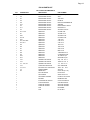
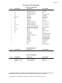
ES-102 PARTS LIST
ES-101-M12 PCB COMPONENTS
QTY
DESIGNATION
DESCRIPTION
PART NUMBER
1
Z9
INTEGRATED CIRCUIT
4053 (PHILIPS)
1
1
Z8
Z7
INTEGRATED CIRCUIT
INTEGRATED CIRCUIT
4503
74HCT244
1
1
Z5
Z6
INTEGRATED CIRCUIT
INTEGRATED CIRCUIT
LM1881N
MAX 233CPP/ADM233LJM
1
1
Z10
Z3
INTEGRATED CIRCUIT
INTEGRATED CIRCUIT
AD823AN
DS87C520MCL-101M12
1
1
Z11
Z4
INTEGRATED CIRCUIT
INTEGRATED CIRCUIT
LM2937ET-3.3
32.0 MHZ VCTCXO
5
1
R14 - R18
R1
RESISTOR
RESISTOR
27 OHM 1/4W
75 OHM 1/2 W
1
2
R20
R3, R4
RESISTOR
RESISTOR
330 OHM 1/4 W
510 OHM 1/4 W
1
3
R22
R21, R23, R25
RESISTOR
RESISTOR
1.8K 1/4W
2.7K 1/4 W
2
1
R10, R11
R9
RESISTOR
RESISTOR
4.7K 1/4 W
10K 1/4 W
1
1
R8
R7
RESISTOR
RESISTOR
120K 1/4 W
470K 1/4 W
1
1
R2
R6
RESISTOR
RESISTOR
680K 1/4 W
1 MEGOHM 1/4 W
1
1
R5
R24
RESISTOR
RESISTOR
2.2 MEGOHM 1/4W
1K OHM mini pot
1
1
R12
C16
RESISTOR
CERAMIC CAPACITOR
50K OHM mini pot
47pf 50v Cer K
1
7
C15
C7 - C12, C17
CERAMIC CAPACITOR
CERAMIC CAPACITOR
.002uf 50v Cer Z
.1uf 50v Cer Z
1
2
C18
C13, C14
TANTALUM CAPACITOR
ELECTROLYTIC CAPACITOR
22uF TANTALUM
100uf 25v R El
1
1
T2
D4
TRANSFORMER
GREEN LED
429-7216
Green LED (T-1 3/4)
1
2
M12+ RECEIVER
2X5 HEADER
P273T12N15
SFMC-105-01-S-D
1
1
2X5 BOARD STACKER
BATTERY
FW-05-04-L-D-200-156
658-BR2330-1HE
1
2
8 POSITION DIP SWITCH
8 PIN DIP SOCKET
8 POS. DIP SWITCH
8 PIN DIP SOCKET
2
1
20 PIN DIP SOCKET
40 PIN DIP SOCKET
20 PIN DIP SOCKET
40 PIN DIP SOCKET
1
1
PCB
PCB
ES-M12BAT
ES-101-M12
Page 14
ES-102 PARTS LIST (CONTINUED)
CHASSIS COMPONENTS
QTY
DESIGNATION
DESCRIPTION
PART NUMBER
T1
TRANSFORMER
P6465
1
1
D-SUB CONNECTOR
D-SUB CONNECTOR
9 PIN MALE D-SUB
9 PIN FEMALE D-SUB
1
3
D-SUB HOOD
BNC
9 PIN D-SUB HOOD
BNC (UG-1094)
1
1
XLR
ANTENNA
XLR-3-32 (M)
ANTENNA FOR GPS
1
1
GPS ANTENNA CABLE
CLIP AND LENS
GPS ANTENNA CABLE
CLIP & LENS FOR LED
FUSE
FUSE HOLDER
1/2A FUSE
HTA FUSE HOLDER
1
1
3 WIRE BUSHING
LINE CORD
3 WIRE BUSHING
3 WIRE LINE CORD
1
CASE AND HARDWARE
ES-102
1
1
1
F1
OPTIONAL COMPONENTS
QTY
DESIGNATION
DESCRIPTION
PART NUMBER
1
(ANT)
EMI ANTENNA
EMI ANTENNA
1
1
(ANT)
(BBU)
EMI ANTENNA CABLE
PC BOARD
EMI ANTENNA CABLE
ES-1424P
1
1
(DC)
R19 (HR)
FUSE
RESISTOR
2 AMP FUSE
2.2K 1/4 W
1
1
D3 (HR)
Q1 (HR)
DIODE
TRANSISTOR
1N4003
PN2907
1
1
K1 (HR)
(J)
RELAY
TRANSFORMER
1A5A RELAY
P8705/SSA5-6.3/230
1
1
(K)
(K)
PC BOARD
M12+ TIMING RECEIVER
ES-110M12
P283T12T12
1
1
(UL)
(UL)
TRANSFORMER
UL POWER PLUG
AA-061A5-206
UL PWR PLUG
1
(45 nS)
M12+ TIMING RECEIVER
P273T12T17
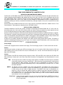
NOTE: THIS EQUIPMENT HAS BEEN TESTED AND FOUND TO COMPLY WITH THE LIMITS FOR A CLASS A DIGITAL
DEVICE, PURSUANT TO PART 15 OF THE FCC RULES. THESE LIMITS ARE DESIGNED TO PROVIDE REASONABLE
PROTECTION AGAINST HARMFUL INTERFERENCE WHEN THE EQUIPMENT IS OPERATED IN A COMMERCIAL
ENVIRONMENT. THIS EQUIPMENT GENERATES, USES AND CAN RADIATE RADIO FREQUENCY ENERGY AND, IF
NOT INSTALLED AND USED IN ACCORDANCE WITH THE INSTRUCTION MANUAL, MAY CAUSE HARMFUL
INTERFERENCE TO RADIO COMMUNICATIONS. OPERATION OF THIS EQUIPMENT IN A RESIDENTIAL AREA IS
LIKELY TO CAUSE HARMFUL INTERFERENCE IN WHICH CASE THE USER WILL BE REQUIRED TO CORRECT THE
INTERFERENCE AT HIS OWN EXPENSE.
IF COMPONENT REMOVAL IS REQUIRED, WE RECOMMEND REMOVING ALL SOLDER USING A 35W OR SMALLER
SOLDERING IRON AND SOLDER WICK TO PREVENT DAMAGE TO THE PRINTED CIRCUIT BOARD.
ALL INFORMATION CONTAINED IN THIS MANUAL IS SUBJECT TO CHANGE WITHOUT NOTICE.
Page 15
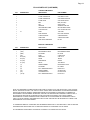
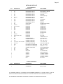
ES-102 PARTS LIST (CONTINUED)
ES-USS PCB COMPONENTS
QTY
DESIGNATION
DESCRIPTION
PART NUMBER
1
Z6
INTEGRATED CIRCUIT
UCN5841A
1
1
Z5
Z1
INTEGRATED CIRCUIT
INTEGRATED CIRCUIT
UCN5895A
7805
1
1
Z2
X1
INTEGRATED CIRCUIT
CRYSTAL
P87C51SBPN-USS1
11.0592MHZ
7
1
R23 - R29
R30
RESISTOR
RESISTOR
47 OHM 1/4W
68 OHM 1/4 W
1
1
R2
R1
RESISTOR
RESISTOR
51K 1/4 W
120K 1/4 W
1
1
C12
C13
CERAMIC CAPACITOR
CERAMIC CAPACITOR
10pf
25pf
3
1
C5, C7, C8
C14
CERAMIC CAPACITOR
ELECTROLYTIC CAPACITOR
.1uf 50v Cer Z
4.7uf 10v R El
1
4
C6
C1 - C4
ELECTROLYTIC CAPACITOR
ELECTROLYTIC CAPACITOR
10uf 16v LL R El
3300 UF 25V
2
1
D1, D2
D3
DIODE
DIODE
1N4003
1N4148 or 1N914
1
1
Q1
TRANSISTOR
HEAT SINK
PN2222
300-TO220 HEAT SINK
1
1
8 POSITION DIP SWITCH
SOCKET
8 POS. DIP SWITCH
16 PIN DIP SOCKET
1
1
SOCKET
SOCKET
18 PIN DIP SOCKET
40 PIN DIP SOCKET
2
3
BRACKET
LTD 6840Y
616 'L' BRACKET
LED DISPLAY
1
1
PCB
PCB
ES-USS
ES-UCT2 DISPLAY
50v Cer K
50v Cer K
CHASSIS COMPONENTS
QTY
2
DESIGNATION
DESCRIPTION
PART NUMBER
T1, T2
TRANSFORMER
P6465
OPTIONAL COMPONENTS
QTY
DESIGNATION
DESCRIPTION
PART NUMBER
1
(DC)
DC/DC CONVERTER
1505D20UR
1
1
(DC/BBU) (12 - 18 V)
(DC/BBU) (18 - 35 V)
DC/DC CONVERTER
DC/DC CONVERTER
UM2804
1505D20UR
IF COMPONENT REMOVAL IS REQUIRED, WE RECOMMEND REMOVING ALL SOLDER USING A 35W OR SMALLER
SOLDERING IRON AND SOLDER WICK TO PREVENT DAMAGE TO THE PRINTED CIRCUIT BOARD.
ALL INFORMATION CONTAINED IN THIS MANUAL IS SUBJECT TO CHANGE WITHOUT NOTICE.
Page 16
OPTION K PARTS LIST
PCB COMPONENTS
QTY
DESIGNATION
DESCRIPTION
PART NUMBER
1
Z1
INTEGRATED CIRCUIT
4503
1
1
Z2
Z3
INTEGRATED CIRCUIT
INTEGRATED CIRCUIT
DS87C520MCL-110M12K
74HCT4053 (PHIL)
1
1
Z4
Z5
INTEGRATED CIRCUIT
INTEGRATED CIRCUIT
74HC4046
74HCT93 (NO LS)
6
1
Z7 - Z12
Z13
INTEGRATED CIRCUIT
INTEGRATED CIRCUIT
74HC161
74HC14
1
1
Z14
Z16
INTEGRATED CIRCUIT
INTEGRATED CIRCUIT
CLC 409AJP
LMV7219
1
1
Z17
Z6
INTEGRATED CIRCUIT
OSCILLATOR
AD823AN
20.0 MHz OSCILLATOR
2
3
R3, R21
R12, R13, R27
RESISTOR
RESISTOR
10 OHM 1/4 W
27 OHM 1/4W
1
1
R2
R17
RESISTOR
RESISTOR
47 OHM 1/4W
100 OHM 1/4 W
1
1
R22
R5
RESISTOR
RESISTOR
330 OHM 1/4 W
390 OHM 1/4 W
1
2
R7
R4, R16
RESISTOR
RESISTOR
510 OHM 1/4 W
1K 1/4 W
5
1
R8, R14, R18 - R20
R15
RESISTOR
RESISTOR
10K 1/4 W
10 MEGOHM 1/4 W
1
1
R6
C21
POTENTIOMETER
CERAMIC CAPACITOR
1K OHM mini pot
47pf 50v Cer K
1
13
C15
C1, C3 - C6, C8 - C14, C28
CERAMIC CAPACITOR
CERAMIC CAPACITOR
.01uf 50v Cer Z
.1uf 50v Cer Z
2
1
C22, C23
C29
POLY FILM CAPACITOR
ELECTROLYTIC CAPACITOR
4.7uF POLY FILM 100V
10uf 16v LL R El
1
1
C2
C20
ELECTROLYTIC CAPACITOR
VARIABLE CAPACITOR
1000uf 16v R El
5-30 PF TRIMM 5MM V
1
1
D2
D3
LED
DIODE
Green LED (T-1 3/4)
1N4740
1
1
L1
INDUCTOR
SOCKET
3.3 uH INDUCTOR
8 PIN DIP SOCKET
2
9
SOCKET
SOCKET
14 PIN DIP SOCKET
16 PIN DIP SOCKET
1
1
SOCKET
PCB
40 PIN DIP SOCKET
ES-110M12
CHASSIS COMPONENTS
QTY
1
2
DESIGNATION
DESCRIPTION
PART NUMBER
CLIP & LENS FOR LED
CONNECTOR
CLIP & LENS FOR LED
BNC (UG-1094)
IF COMPONENT REMOVAL IS REQUIRED, WE RECOMMEND REMOVING ALL SOLDER USING A 35W OR
SMALLER SOLDERING IRON AND SOLDER WICK TO PREVENT DAMAGE TO THE PRINTED CIRCUIT BOARD.
ALL INFORMATION CONTAINED IN THIS MANUAL IS SUBJECT TO CHANGE WITHOUT NOTICE.
Page 17
Page 18
Page 19
Page 20
Page 21
Page 22